
Equivalent Relationship of the Mechanical Behavior of Ring Nets under Static Punching and Dynamic Impact Conditions

 ,
, 
Abstract
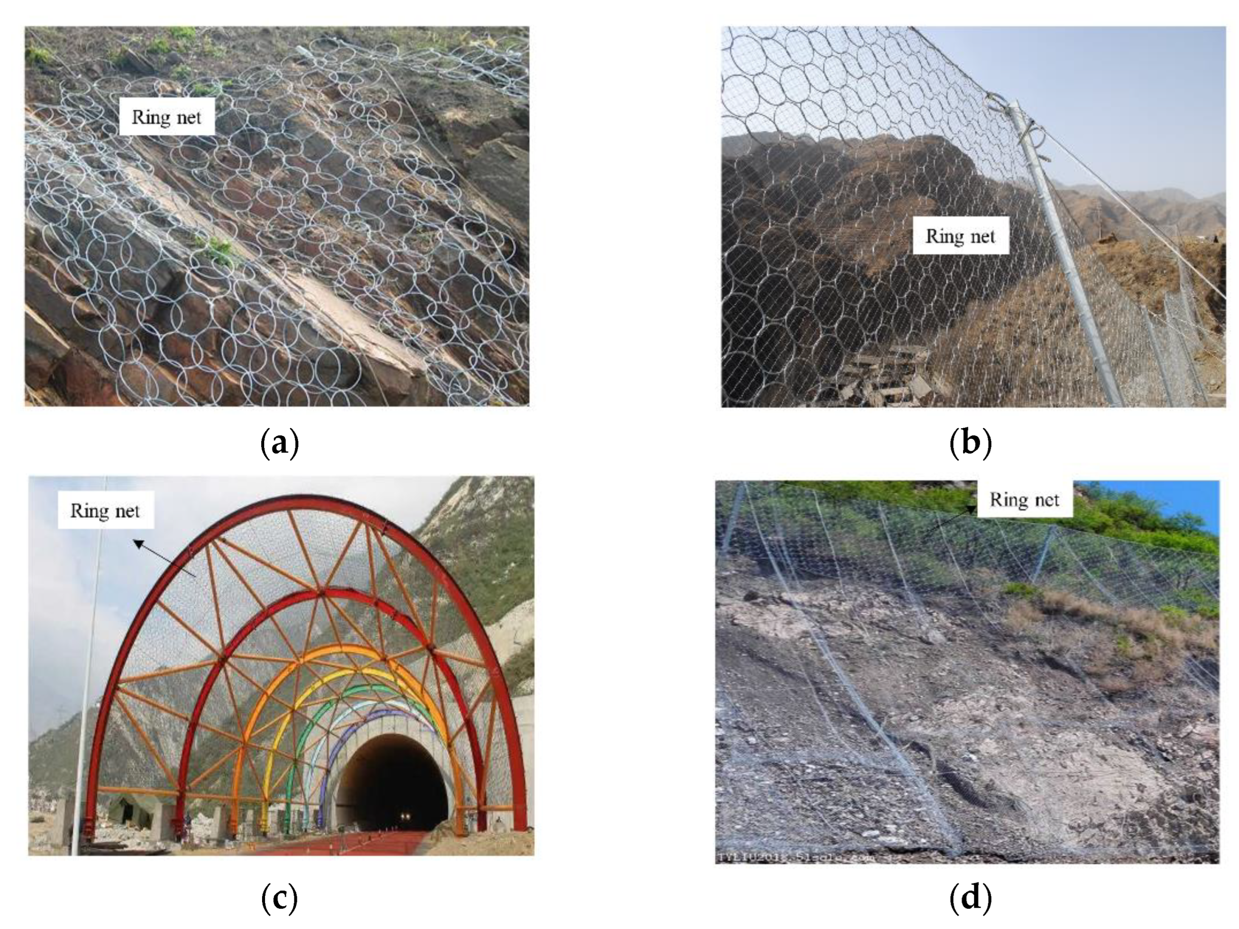
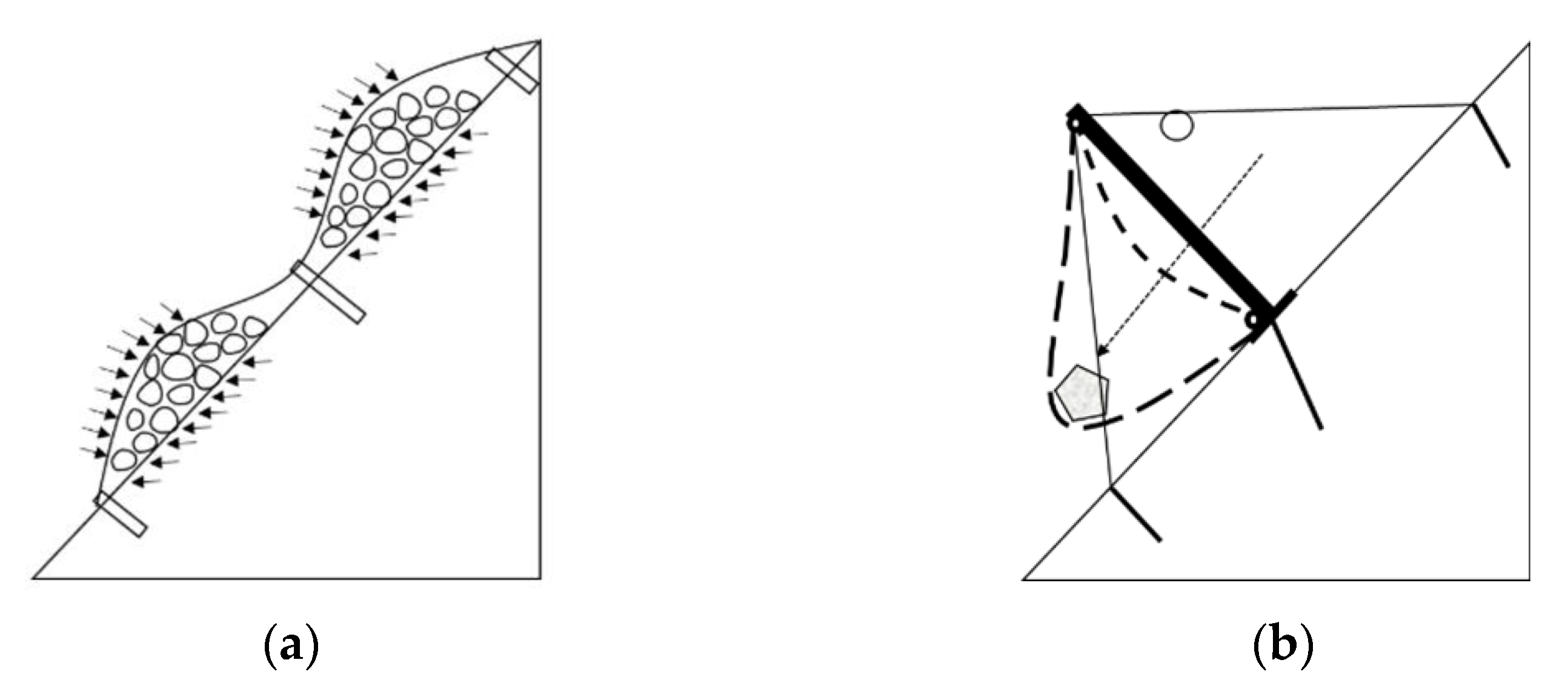
:1. Introduction
2. Static Punching Test
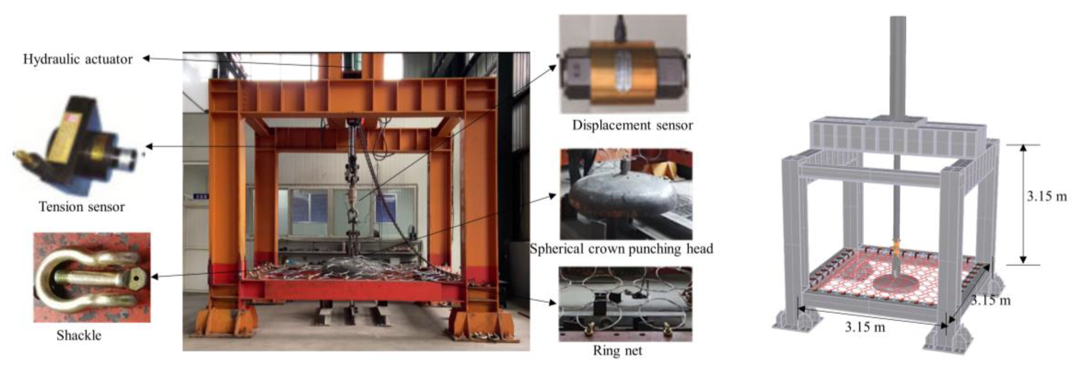
2.1. Test Equipment
2.2. Test Conditions and Loading Methods
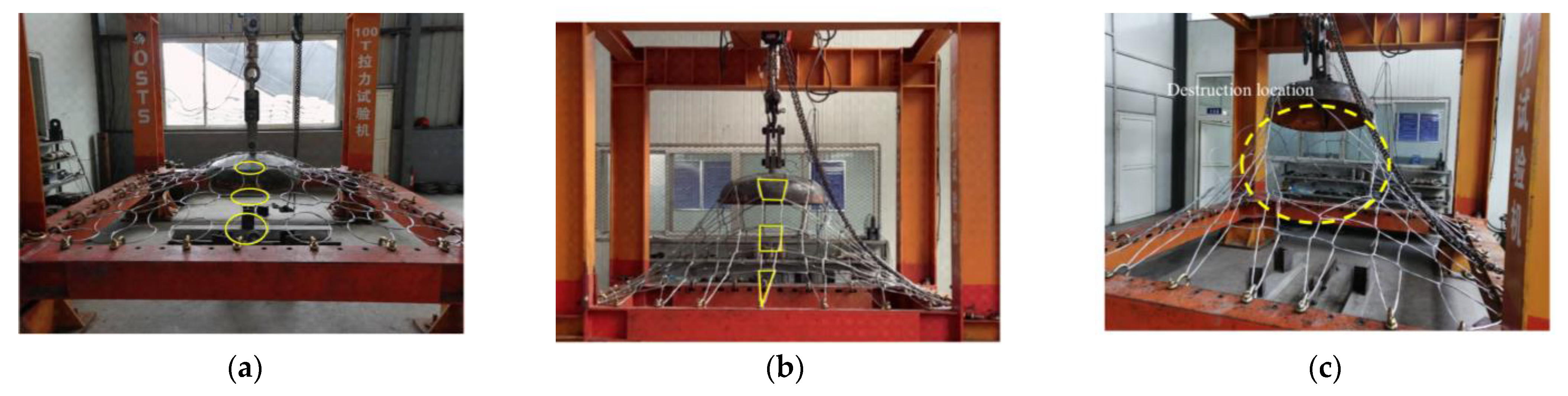
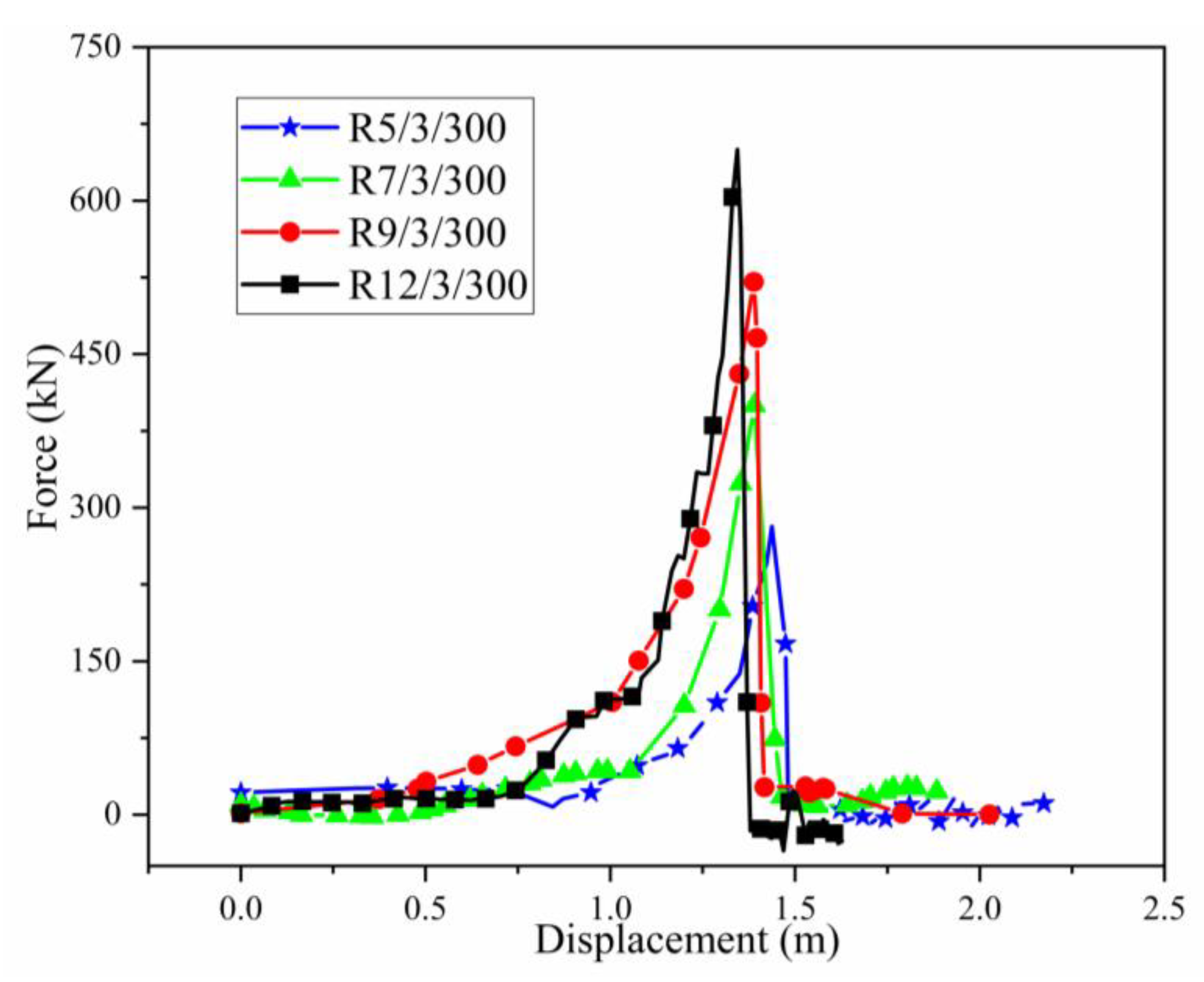
2.3. Static Test Process and Results
3. Dynamic Impact Test
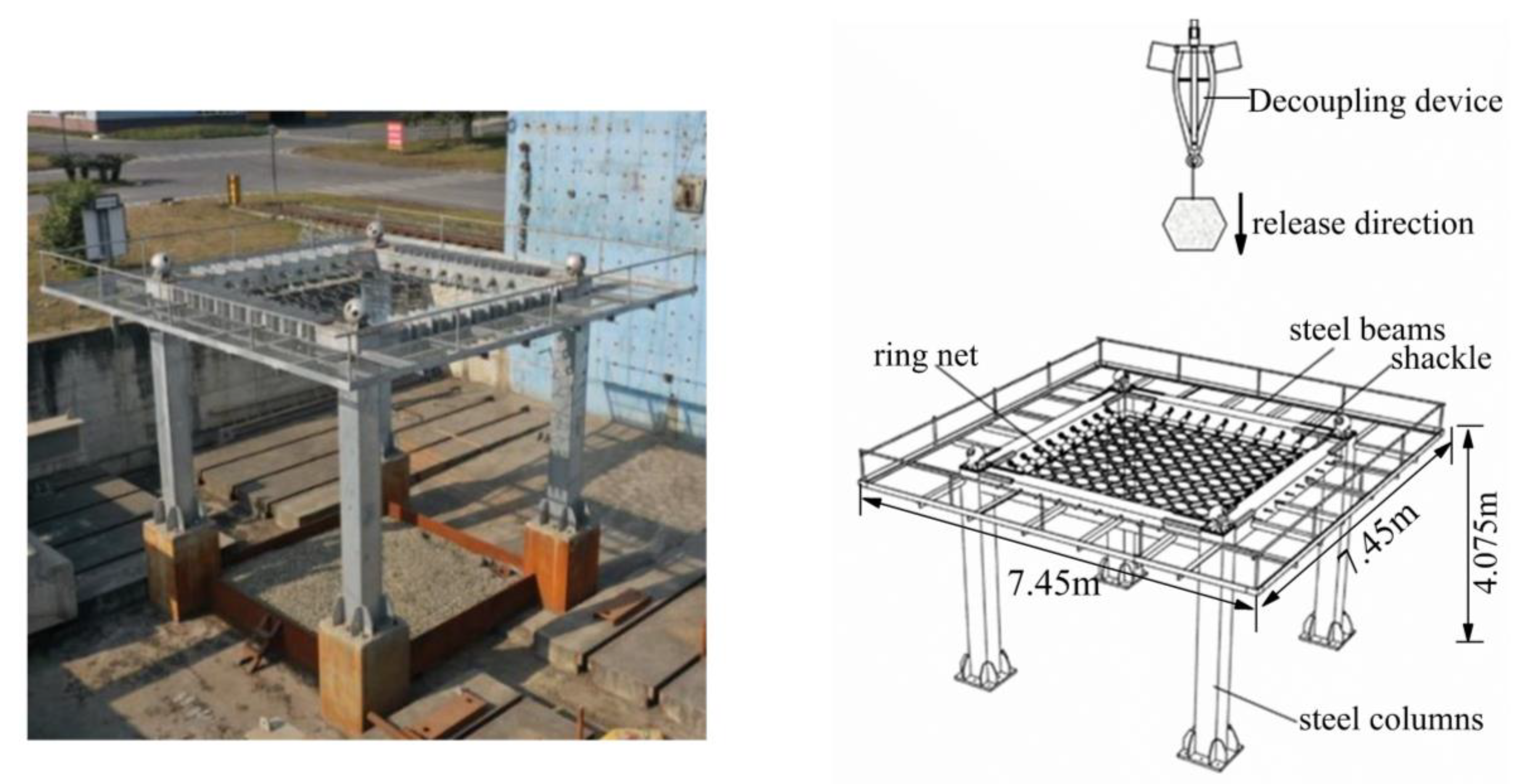
3.1. Test Equipment
3.2. Test Conditions and Loading Methods
3.3. Dynamic Test Process and Results
4. Comparative Analysis of Static and Dynamic Test Results
5. Parametric Analysis
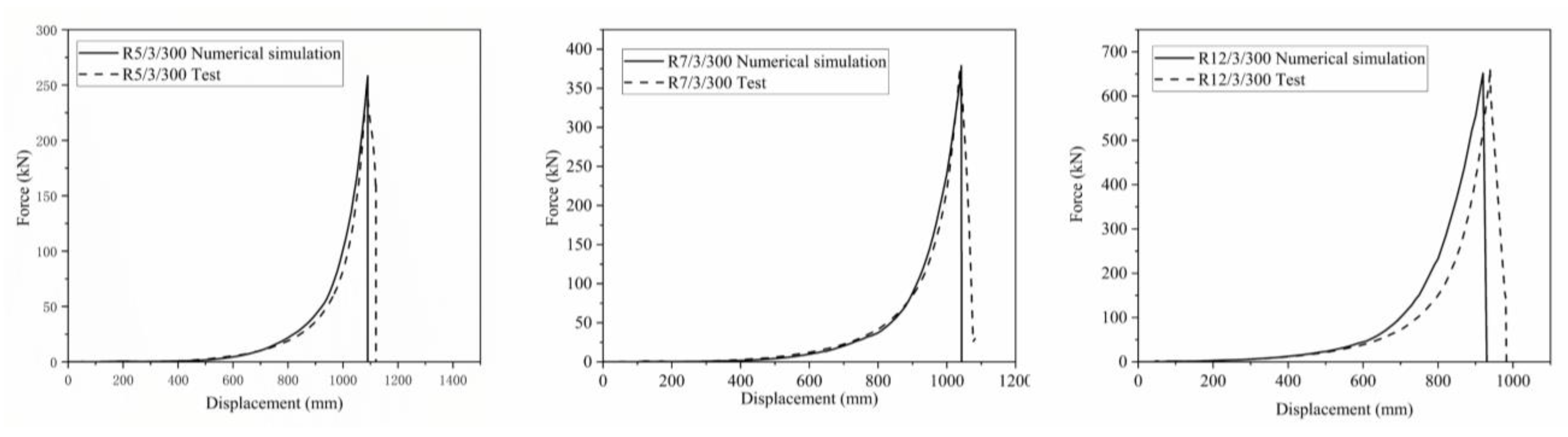
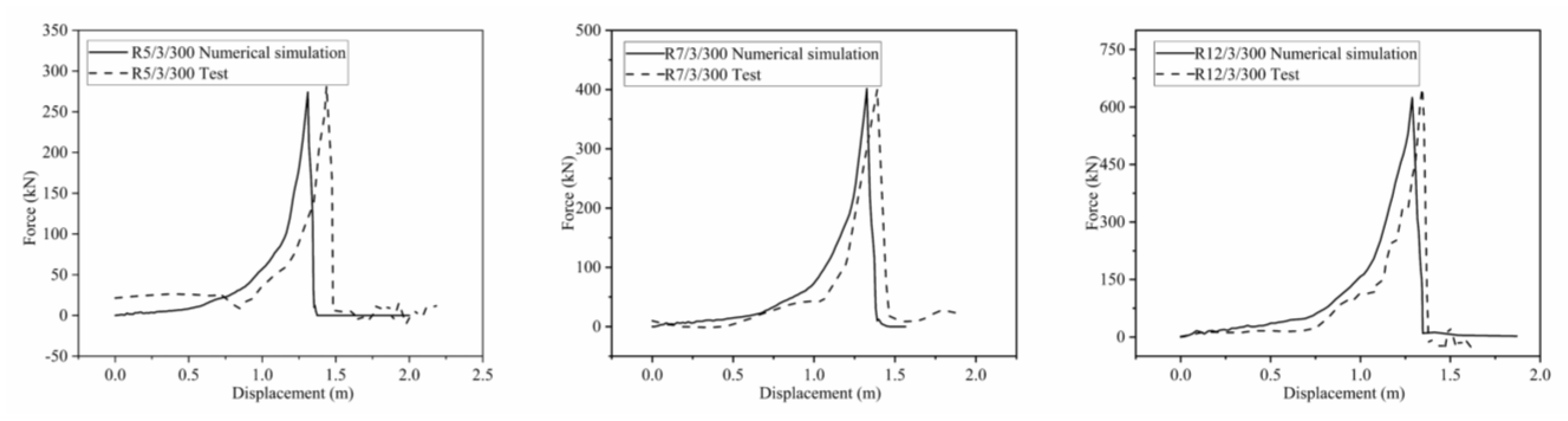
5.1. Comparative Analysis of Finite Element Simulation and Test
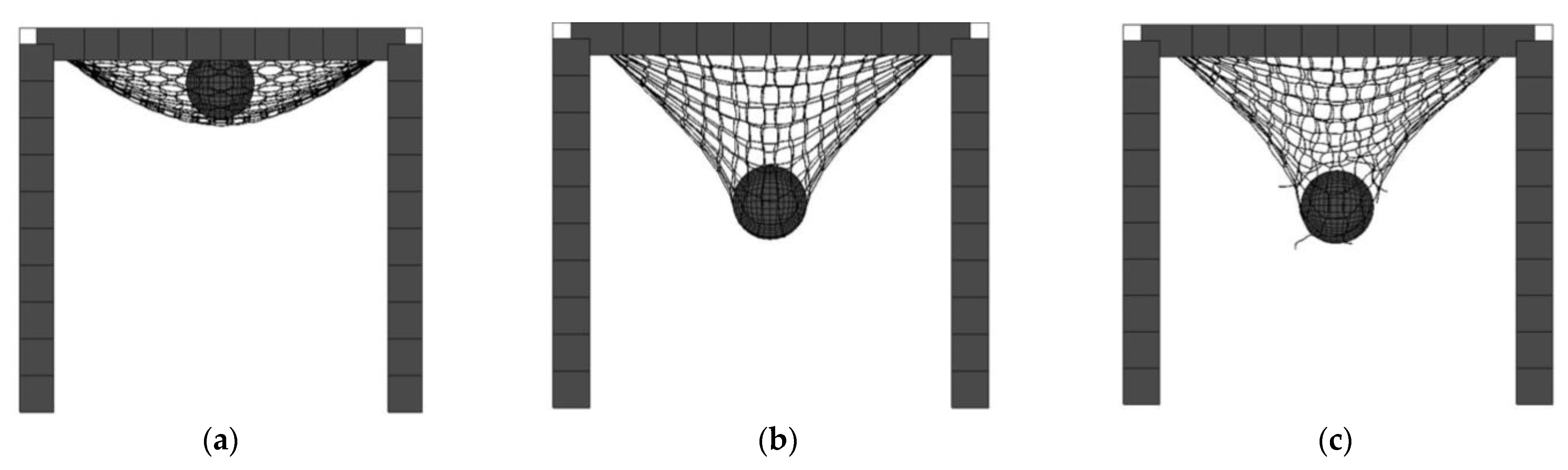
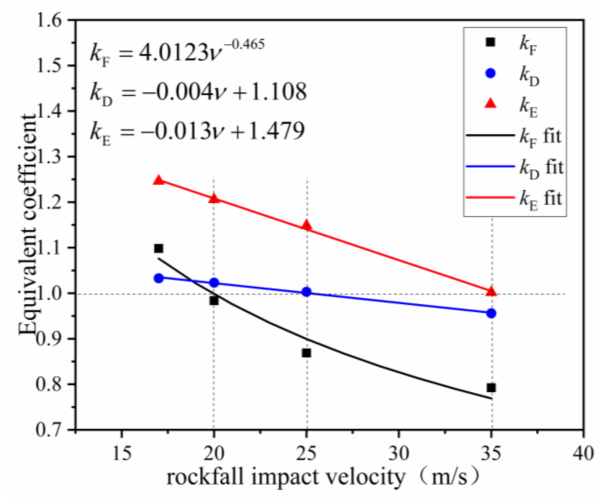
5.2. Analysis of Rockfall Impact Velocity
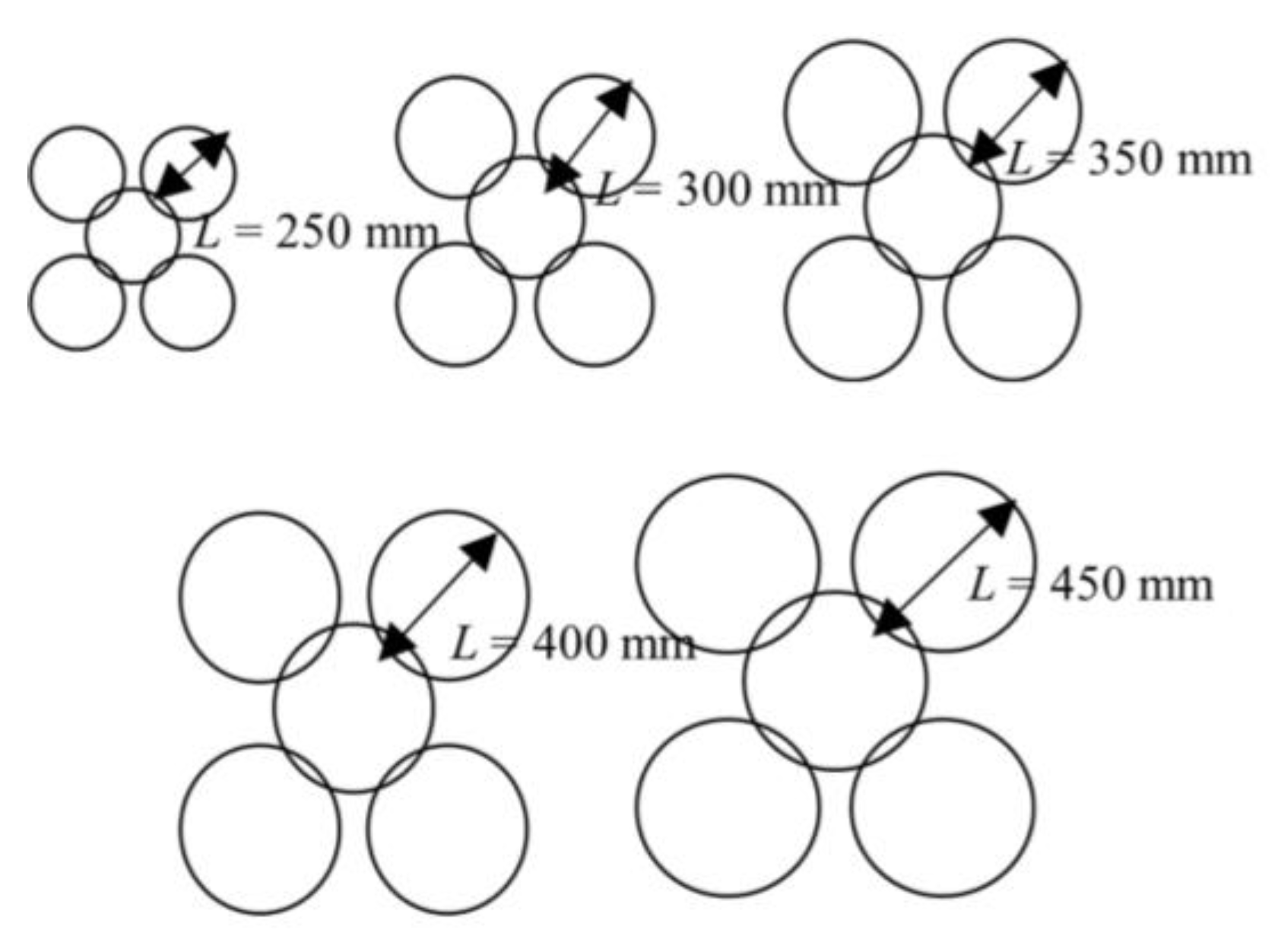
5.3. Analysis of the Influence of Ring Diameter
5.4. Analysis of the Influence of Ring Net Aspect Ratio
5.5. Analysis of the Influence of the Loading Head Area to Ring Net Area Ratio
5.6. Analysis of Equivalence Coefficient Sensitivity
6. Equivalence of Static Punching and Dynamic Impact Results
7. Conclusions
- With an increase in the impact velocity, the equivalent coefficient of the breaking force of the ring net decreased as a power function, and the equivalent coefficients of tensile displacement and energy consumption decreased linearly. When the impact velocity was greater than 35 m/s, the breaking force, the breaking displacement, and the energy consumption of the ring net under static punching test were larger than those under dynamic impact test.
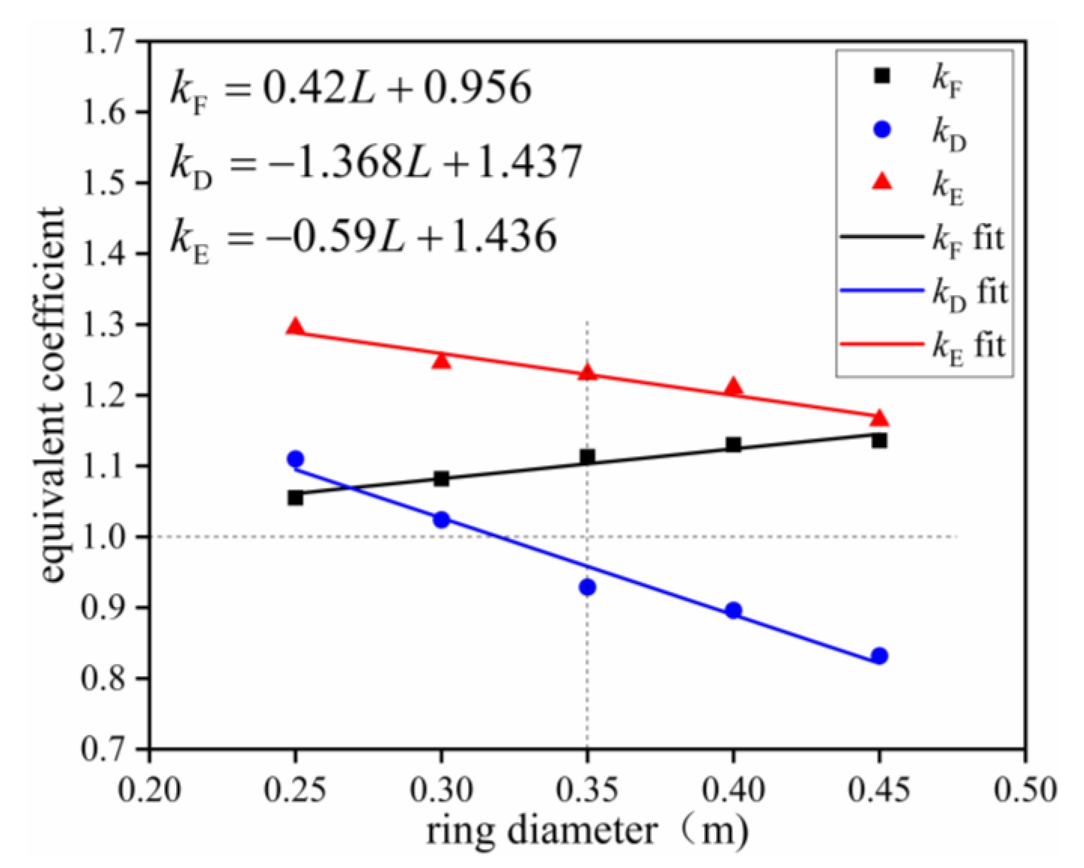
- With an increase in ring diameter, the equivalent coefficient of the ring net breaking force increased linearly, and the equivalent coefficients of ring net tensile displacement and energy consumption decreased linearly. When the ring diameter is greater than 350 mm, the rupture displacement predicted by the static punching test will be larger than that predicted by the dynamic impact test.
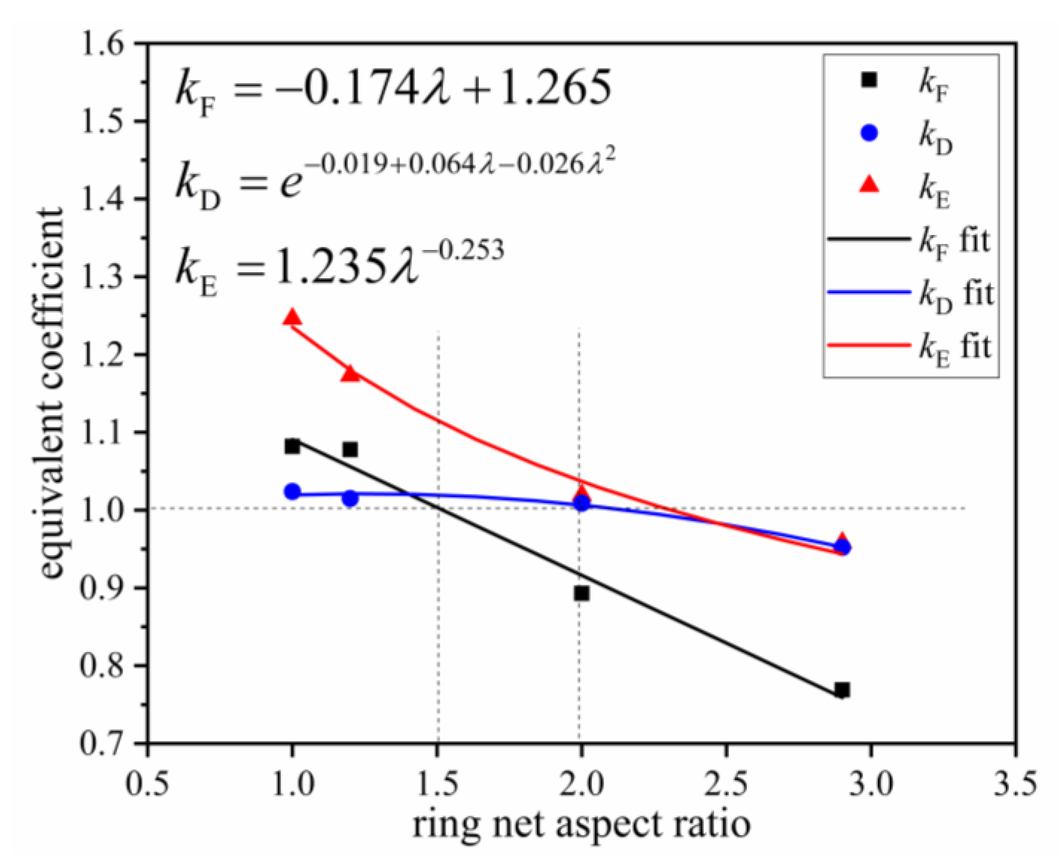
- With an increase in ring net aspect ratio, the equivalent coefficient of ring net breaking force decreased linearly. The exponential function of the equivalent coefficient of tensile displacement also decreased, and the equivalent coefficient of ring net energy consumption decreased as a power function. When the aspect ratio is higher than 2, the breaking force, the breaking displacement, and the energy consumption of the mesh under static punching test will be larger than those under the dynamic impact test.
- With an increase in the ratio of the loading head area to the ring net area, the power function of the equivalent coefficient of the ultimate breaking force increased, the equivalent coefficient of ring net tensile displacement decreased linearly, and the equivalent coefficient of ring net energy consumption increased linearly.
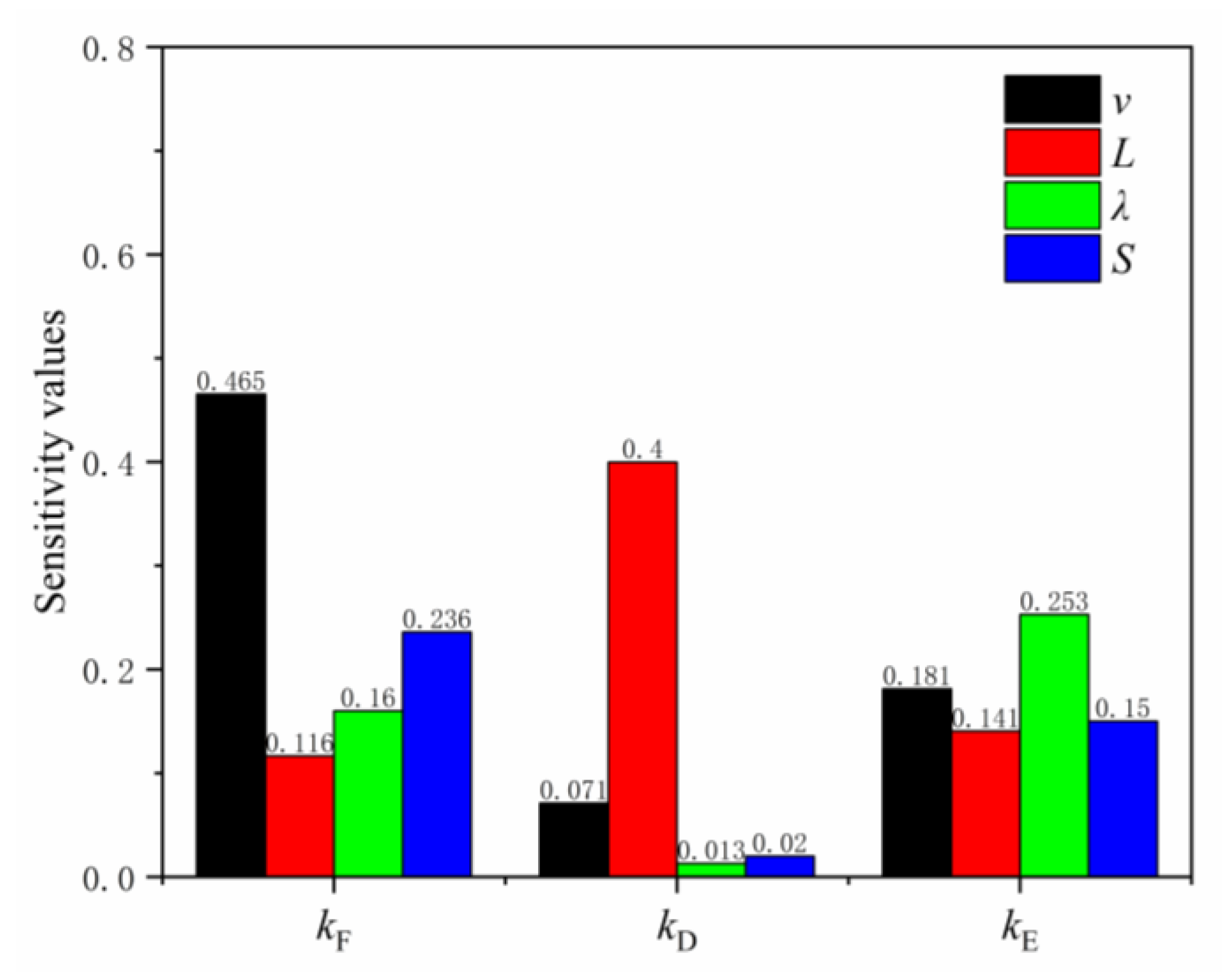
- The degree of influence of the parameters was as follows: impact velocity (v) > ring diameter (L) > ring net length to width ratio (λ) > ratio of loading head area to ring net area (S).
- Models considering the effect of impact velocity, ring diameter, ring net aspect ratio, and ratio of the loading head area to the ring net area were built to reveal ring net performance under static punching and dynamic impact conditions.
Author Contributions
Funding
Data Availability Statement
Conflicts of Interest
References
- Escallon, J.P.; Boetticher, V.; Wendeler, C.; Chatzi, E.; Bartelt, P. Mechanics of chain-link wire nets with loose connections. Eng. Struct. 2015, 101, 68–87. [Google Scholar] [CrossRef]
- Castro-Fresno, D.; Luis, L.Q.; Bianco-Fernandez, E.; Zamora-Barraza, D. Design and evaluation of two laboratory tests for the nets of a flexible anchored slope stabilization system. Geotech. Test. J. 2014, 32, 315–324. [Google Scholar] [CrossRef]
- Bertrand, D.; Trad, A.; Chauvel, R.; Limam, A. Discrete element simulation of an innovative metallic net dedicated to rockfall protection: A multi-scale approach. In Third Euro Mediterranean Symposium on Advances in Geomaterials and Structures; LGC-ENIT: Djerba, Tunisie, 2010. [Google Scholar]
- Bertrand, D.; Trad, A.; Limam, A.; Silvani, C. Full-scale dynamic analysis of an innovative rockfall fence under impact using the discrete element method: From the local scale to the structure scale. Rock Mech. Rock Eng. 2012, 45, 885–900. [Google Scholar] [CrossRef]
- Albrecht, V.B.; Axel, V. Numerical modelling of chain-link steel wire nets with discrete elements. Can. Geotech. J. 2019, 56, 398–419. [Google Scholar] [CrossRef]
- Xu, H.; Gentilini, C.; Yu, Z.; Qi, X.; Zhao, S. An energy allocation based design approach for flexible rockfall protection barriers. Eng. Struct. 2018, 173, 831–852. [Google Scholar] [CrossRef]
- Nicot, F.; Cambou, B.; Mazzoleni, G. From a constitutive modelling of metallic rings to the design of rockfall restraining nets. Int. J. Numer. Anal. Methods Geomech. 2015, 25, 49–70. [Google Scholar] [CrossRef]
- Paola, B.; Claudio, O.; Daniele, P. Full-scale testing of draped nets for rock fall protection. Can. Geotech. J. 2009, 46, 306–317. [Google Scholar] [CrossRef]
- Antonio, P.; Fabio, G.; Lorenzo, B. Discrete element analysis of the punching behaviour of a secured drapery system: From laboratory characterization to idealized in situ conditions. Acta Geotech. 2021, 16, 2553–2573. [Google Scholar] [CrossRef]
- Peila, D.; Pelizza, S.; Sassudelli, F. Evaluation of Behaviour of Rockfall Restraining Nets by Full Scale Tests. Rock Mech. Rock Eng. 1998, 31, 1–24. [Google Scholar] [CrossRef]
- Gerber, W.; Boell, A. Type-Testing of Rockfall Barriers-Comparative Results: International Proceedings of the Interpraevent Congress; Universal Academy Press, Inc.: Nigata, Japan, 2006. [Google Scholar]
- Tan, D.; Yin, J.; Qin, J.; Zhu, Z. New thoughts for impact force estimation on flexible barriers. In Advancing Culture of Living with Landslides; Springer International Publishing: Ljubljana, Slovenia, 2017; pp. 457–463. [Google Scholar] [CrossRef]
- Buzzi, O.; Spadari, M.; Giacomini, A.; Fityus, S.; Sloan, S.W. Experimental testing of rockfall barriers designed for the low range of impact energy. Rock Mech. Rock Eng. 2013, 46, 701–712. [Google Scholar] [CrossRef]
- Buzzi, O.; Leonarduzzi, E.; Krummenacher, B.; Volkwein, A.; Giacomini, A. Performance of high strength rock fall meshes: Effect of block size and mesh geometry. Rock Mech. Rock Eng. 2015, 48, 1221–1231. [Google Scholar] [CrossRef]
- Yu, Z.X.; Qiao, Y.K.; Zhao, L.; Xu, H.; Zhao, S.C.; Liu, Y.P. A simple analytical method for evaluation of flexible rockfall barrier part 1: Working mechanism and analytical solution. Adv. Steel Constr. 2018, 14, 115–141. [Google Scholar] [CrossRef]
- Koo, R.C.H.; Kwan, J.S.H.; Lam, C.; Ng, C.W.W.; Yiu, J.; Choi, C.E.; Ng, A.K.L.; Ho, K.K.S.; Pun, W.K. Dynamic response of flexible rockfall barriers under different loading geometries. Landslides. 2017, 14, 905–916. [Google Scholar] [CrossRef]
- Qi, X.; Pei, X.; Han, R.; Yang, Y.; Meng, Q.; Yu, Z. Analysis of the effects of a rotating rock on rockfall protection barriers. Geotech. Geol. Eng. 2018, 36, 3255–3267. [Google Scholar] [CrossRef]
- EOTA. Falling Rock Protection Kits. EAD 340059–00–0106, 2018/C417/07. European Organisation for Technical Assessment, Avenue des Arts 40 Kunstlaan, B—1040 Brussels. 2018. Available online: https://www.eota.eu/eads (accessed on 5 February 2023).
- Guo, L.; Yu, Z.; Luo, L.; Qi, X.; Zhao, S. An analytical method of puncture mechanical behavior of ring nets based on the load path equivalence. Eng. Mech. 2020, 37, 129–139. (In Chinese) [Google Scholar] [CrossRef]
- Livermore Software Technology Corporation. LSTC LS-DYNA R7.1 Keyword User’s Manual Vol I; Livermore Software Technology Corporation: Troy, MI, USA, 2005. [Google Scholar]
- Livermore Software Technology Corporation. LSTC LS-DYNA R7.1 Keyword User’s Manual Vol II; Livermore Software Technology Corporation: Troy, MI, USA, 2005. [Google Scholar]
- Zhang, L.Y. Study on Damage Mechanical Behavior of Wire-Ring Net under Repeated Impacts. Bachelor’s Thesis, Southwest Jiaotong University, Chengdu, China, 2019. [Google Scholar]
- Li, Z.M. Study on the Mechanical Behavior of the Flexible Intercepting Net. Bachelor’s Thesis, Southwest Jiaotong University, Chengdu, China, 2016. [Google Scholar]
- Zhao, S.C.; Yu, Z.X.; Wei, T.; Qi, X. Test study of force mechanism and numerical calculation of safety netting system. China Civ. Eng. J. 2013, 46, 122–128. (In Chinese) [Google Scholar] [CrossRef]
- Qi, X.; Yu, Z.X.; Zhao, L.; Xu, H.; Zhao, S.C. A new numerical modelling approach for flexible rock fall protection barriers based on failure mode. Adv. Steel Construction 2018, 14, 479–495. [Google Scholar]
- Yu, Z.; Liu, C.; Guo, L.; Zhao, L.; Zhao, S. Nonlinear Numerical Modeling of the Wire-Ring Net for Flexible Barriers. Shock Vib. 2019, 2019, 3040213. [Google Scholar] [CrossRef]
- T/CECS 824-2021; Technical Specification for Passive Flexible Protection Barrier Structure Engineering. China Association for Engineering Construction Standardization: Beijing, China, 2021.


| Specifications | Windings Number | Wire Diameter (mm) | Ring Diameter (mm) | Sets |
|---|---|---|---|---|
| R5/3/300 | 5 | 3 | 300 | 3 |
| R7/3/300 a | 7 | 3 | 300 | 3 |
| R9/3/300 | 9 | 3 | 300 | 3 |
| R12/3/300 | 12 | 3 | 300 | 3 |
| Specifications | Breaking Displacement (mm) | Standard Deviation | Breaking Force (kN) | Standard Deviation | Energy Dissipation (kJ) | Standard Deviation |
|---|---|---|---|---|---|---|
| R5/3/300 | 1090 | 8.58 | 245.20 | 25.67 | 29.6 | 0.43 |
| R7/3/300 | 1035 | 11.43 | 379.0 | 4.80 | 38.1 | 0.67 |
| R9/3/300 | 1029 | 20.85 | 509.0 | 36.37 | 57.0 | 1.50 |
| R12/3/300 | 930 | 8.06 | 666.7 | 48.71 | 82.5 | 1.88 |
| Specifications | Winding Number | Ring Diameter (mm) | Lift Height (m) | Impact Velocity (m/s) | Impact Energy (kJ) |
|---|---|---|---|---|---|
| R5/3/300 | 5 | 300 | 7.57 | 13.33 | 67.5 |
| R7/3/300 | 7 | 300 | 13.29 | 17.09 | 111 |
| R9/3/300 | 9 | 300 | 16.46 | 18.85 | 135 |
| R12/3/300 | 12 | 300 | 22.78 | 21.94 | 183 |
| Specifications | Breaking Displacement (m) | Breaking Force (kN) | Energy Dissipation (kJ) | The Absorbed Energy with Respect to the Impact Energy (%) |
|---|---|---|---|---|
| R5/3/300 | 1.430 | 281.2 | 48.7 | 72.15 |
| R7/3/300 | 1.394 | 400.5 | 75.3 | 67.84 |
| R9/3/300 | 1.389 | 521.0 | 95.1 | 70.44 |
| R12/3/300 | 1.291 | 649.8 | 138.3 | 75.57 |
| Specifications | Breaking Displacement (m) | Breaking Force (kN) | Energy Dissipation (kJ) |
|---|---|---|---|
| R5/3/300 | 1.410 | 252.85 | 43.57 |
| R7/3/300 | 1.389 | 367.87 | 63.03 |
| R9/3/300 | 1.369 | 490.71 | 83.60 |
| R12/3/300 | 1.233 | 689.52 | 116.46 |
| Component Name | Density (kg·m3) | Elastic Modulus (105 MPa) | Poisson’s Ratio (Mpa) |
|---|---|---|---|
| Ring net | 7850 | 2.00 | 0.3 |
| Loading side | 2873 | 2.00 | 0.3 |
| Shackle | 7900 | 2.06 | 0.3 |
| Component Name | Density (kg·m3) | Elastic Modulus (105 MPa) | Poisson’s Ratio | Yield Strength (Mpa) |
|---|---|---|---|---|
| Steel column beam | 7900 | 0.3 | 345 | |
| Ring net | 7850 | 0.3 | — | |
| Rockfall | 2873 | 0.3 | — | |
| Shackles | 7900 | 0.3 | — |
| Model | Winding Turns | Rockfall Impact Velocity (ν, m/s) | Ring Diameter (L, mm) | Ring Net Aspect Ratio (λ) | Loading Head Area to Ring Net Area Ratio (S) | kF | kD | kE |
|---|---|---|---|---|---|---|---|---|
| 1 | 7 | 17 | 300 | 1.0 | 0.033 | 1.082 | 1.024 | 1.246 |
| 2 | 7 | 20 | 300 | 1.0 | 0.033 | 0.984 | 1.015 | 1.206 |
| 3 | 7 | 25 | 300 | 1.0 | 0.033 | 0.869 | 0.995 | 1.148 |
| 4 | 7 | 35 | 300 | 1.0 | 0.033 | 0.792 | 0.948 | 1.002 |
| 5 | 7 | 17 | 250 | 1.0 | 0.033 | 1.055 | 1.110 | 1.295 |
| 6 | 7 | 17 | 300 | 1.0 | 0.033 | 1.082 | 1.024 | 1.246 |
| 7 | 7 | 17 | 350 | 1.0 | 0.033 | 1.113 | 0.929 | 1.230 |
| 8 | 7 | 17 | 400 | 1.0 | 0.033 | 1.130 | 0.896 | 1.211 |
| 9 | 7 | 17 | 450 | 1.0 | 0.033 | 1.136 | 0.832 | 1.165 |
| 10 | 7 | 17 | 300 | 1.0 | 0.033 | 1.082 | 1.024 | 1.246 |
| 11 | 7 | 17 | 300 | 1.2 | 0.033 | 1.078 | 1.015 | 1.173 |
| 12 | 7 | 17 | 300 | 2.0 | 0.033 | 0.893 | 1.009 | 1.019 |
| 13 | 7 | 17 | 300 | 3.0 | 0.033 | 0.769 | 0.952 | 0.958 |
| 14 | 7 | 17 | 300 | 1.0 | 0.033 | 1.082 | 1.024 | 1.246 |
| 15 | 7 | 17 | 300 | 1.0 | 0.042 | 1.168 | 1.016 | 1.284 |
| 16 | 7 | 17 | 300 | 1.0 | 0.052 | 1.188 | 1.008 | 1.330 |
| 17 | 7 | 17 | 300 | 1.0 | 0.062 | 1.270 | 1.006 | 1.412 |
Disclaimer/Publisher’s Note: The statements, opinions and data contained in all publications are solely those of the individual author(s) and contributor(s) and not of MDPI and/or the editor(s). MDPI and/or the editor(s) disclaim responsibility for any injury to people or property resulting from any ideas, methods, instructions or products referred to in the content. |
© 2023 by the authors. Licensee MDPI, Basel, Switzerland. This article is an open access article distributed under the terms and conditions of the Creative Commons Attribution (CC BY) license (https://creativecommons.org/licenses/by/4.0/).
Share and Cite
Qi, X.; Deng, Q.; Zhao, L.; Yuan, S.; Li, Z.; Wang, X.; Yu, Z. Equivalent Relationship of the Mechanical Behavior of Ring Nets under Static Punching and Dynamic Impact Conditions. Buildings 2023, 13, 588. https://doi.org/10.3390/buildings13030588
Qi X, Deng Q, Zhao L, Yuan S, Li Z, Wang X, Yu Z. Equivalent Relationship of the Mechanical Behavior of Ring Nets under Static Punching and Dynamic Impact Conditions. Buildings. 2023; 13(3):588. https://doi.org/10.3390/buildings13030588
Chicago/Turabian StyleQi, Xin, Qianqian Deng, Lei Zhao, Song Yuan, Zhenliang Li, Xibao Wang, and Zhixiang Yu. 2023. "Equivalent Relationship of the Mechanical Behavior of Ring Nets under Static Punching and Dynamic Impact Conditions" Buildings 13, no. 3: 588. https://doi.org/10.3390/buildings13030588