Article

Investigation on Minute Holes of Woven Fabrics for Wide-Band Micro-Perforated Sound Absorbers

1
Engineering Physics, Faculty of Industrial Technology, Institut Teknologi Bandung, Bandung 40132, Indonesia
2
Textile Engineering, Politeknik STTT Bandung, Bandung 40272, Indonesia
3
Fakulti Kejuruteraan Mekanikal, Universiti Teknikal Malaysia Melaka, Hang Tuah Jaya, Durian Tunggal, Melaka 76100, Malaysia
4
Faculty of Resilience, Rabdan Academy, Abu Dhabi P.O. Box 40132, United Arab Emirates
*
Authors to whom correspondence should be addressed.
Buildings 2023, 13(3), 663; https://doi.org/10.3390/buildings13030663
Submission received: 6 February 2023 / Revised: 23 February 2023 / Accepted: 24 February 2023 / Published: 2 March 2023
(This article belongs to the Special Issue Towards Acoustic Comfort in Buildings)

Abstract

:
Woven fabric perforation is helpful to be adopted to meet the microstructure requirement of a micro-perforated panel (MPP) absorber. Unlike conventional MPP, the woven fabric micro-perforations are formed by yarn in the x (weft) and y (warp)-directions. Hence, minute holes of the MPP with a diameter of 0.1–0.3 mm or a high perforation ratio are expected to be easily fabricated, while such a specification is difficult to realize on a solid surface, as found in some studies. The study presented here focuses on the use of minute holes in MPP absorbers by woven fabrics and discusses the minute hole properties of woven fabrics and their associated absorption characteristics. Theoretical results by Maa’s model are also used to validate resulting characteristics found from the experimental investigations. It is found that minute holes with around 0.10–0.20 mm diameter have been successfully fabricated by controlling weft yarn density. The woven fabrics are capable of producing half-absorption bandwidth of up to 5000 Hz (>3 octaves), while the peak of the absorption coefficient can be more than 0.8. In addition, varying hole diameter with the order of 10−2 mm can change the absorption behavior for both peak absorption and absorption bandwidth. Such behavior is confirmed by comparing the results with the theoretical model. This study also indicates that Maa’s model is still applicable for predicting absorption of MPP developed based on woven fabric material.

1. Introduction

Micro-perforated panel (MPP) absorbers have been utilized in many noise control treatments [1,2,3,4,5]. They have been an alternative absorber to mineral fibrous porous material absorbers due to health and environmental issues. Theoretically, this kind of absorber performance is governed by perforation parameters and cavity depth, as indicated in theoretical models formulated by Maa [6,7]. With these parameters, the behavior of MPP can be optimally tuned to meet specific absorption frequencies and amplitudes. Despite this behavior, a narrow absorption bandwidth of MPP has limited its applications, so it is still challenging to find the most efficient ways to cope with this issue.
Some efforts have been conducted to widen the absorption frequency bandwidth of MPP. Generally, there are three approaches used for such purpose: (1) the use of multiple MPPs in a series arrangement or parallel arrangement [8,9,10]; (2) increasing damping capacity by combining MPP and porous media [11,12,13]; and (3) the use of a tiny pore diameter or ultra-perforation [14,15,16]. Although the first and second approaches can increase sound absorption frequency bandwidth, both need more than one MPP unit, leading to structural complexity and increased dimensions. The advantage of the third approach is that it can increase absorption bandwidth of a single MPP, as suggested by Maa [7], and that the wideband absorption of MPP can be theoretically achieved by making a finite hole with a diameter in between 0.1 and 0.3 mm, but, on the other hand, it needs a specific technology for fabrication.
Several feasible methods for producing MPPs have been demonstrated, such as the infiltration method [17] and MEMS technology [18,19]. Alternatively, several researchers have used woven fabric to realize the MPP absorber, such as micro-perforation back by mesh [20] and the cotton yarn with facile dip-coating method [21,22]. In contrast, others focused on modelling and numerical calculations for woven absorptions, such as Pieren [23,24,25], Prasetiyo et al. [26,27], and Onen and Caliskan [28]. Meanwhile, Desendra et al. [29] conducted early investigation on the sound absorption characteristics of commercial woven fabrics under MPP configuration by performing a series of sound absorption measurements.. This fact indicates that weaving technology and woven fabrics are proven for the MPP development apart from the popularity of such materials as finishing materials in the interior design of building due to their vibrant color, strength, and unique fiber orientation. However, these efforts have not yet been discussed specifically with regard to the issue of widening the absorption bandwidth by considering the use of minute holes ranging from 0.1 mm to 0.3 mm, particularly in reference to addressing the linkage between manufacturing techniques and the resulting holes, as well as to how sensitive the resulting absorption characteristics are to such variations.
The purpose of the work presented here is to investigate the relationship of minute hole properties of woven fabrics and their associated absorption characteristics, as well as to investigate the techniques for fabricating such a hole in woven fabrics. The woven fabrics are selected as they are widely used in building applications, while the minute holes are critical for developing a wideband sound absorber with a single layer. It is expected that our work can be an easier alternative to realizing minute holes in MPP while also bridging the gap between MPP specifications and the technical realization of such holes in the textile. For this, we demonstrate the fabrication of minute holes in woven fabrics for a sound absorber system and analyze the relationship of the resulting minute holes and associated absorption characteristics. Technically, such a hole in woven fabrics is created by the interlacing between the weft yarn in the x-direction and the warp yarn in the y-direction. Subsequently, the resulting woven fabrics are experimentally investigated further to collect more evidence on their textile morphology and their associated absorption bandwidths and coefficients. Maa’s model [7] is used to validate the experimental investigations and test the applicability of the model in predicting the absorption behavior of woven fabrics with minute holes. We expect that woven fabrics will be proven for use in MPP absorbers and applicable in the broad area in which woven fabric is normally used, e.g., building and room acoustics.
The remainder of this paper is divided into five sections. Section 2 describes woven fabric fabrication and its associated material properties. Then, in Section 3, characterization methods of geometrical and acoustical properties are presented. Section 4 presents some discussions on the measured absorption coefficients behavior of woven fabrics by looking further at absorption bandwidth and specific impedance characteristics. Theoretical validation of the resulting absorption is presented in Section 5. Finally, some significant results are summarized in the conclusions.

2. Material and Structures

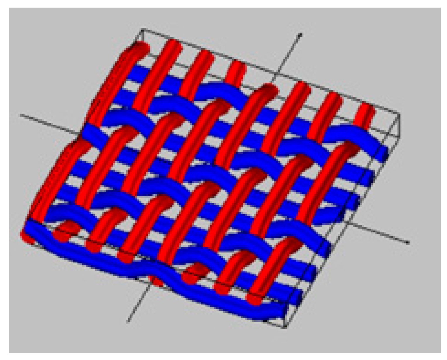
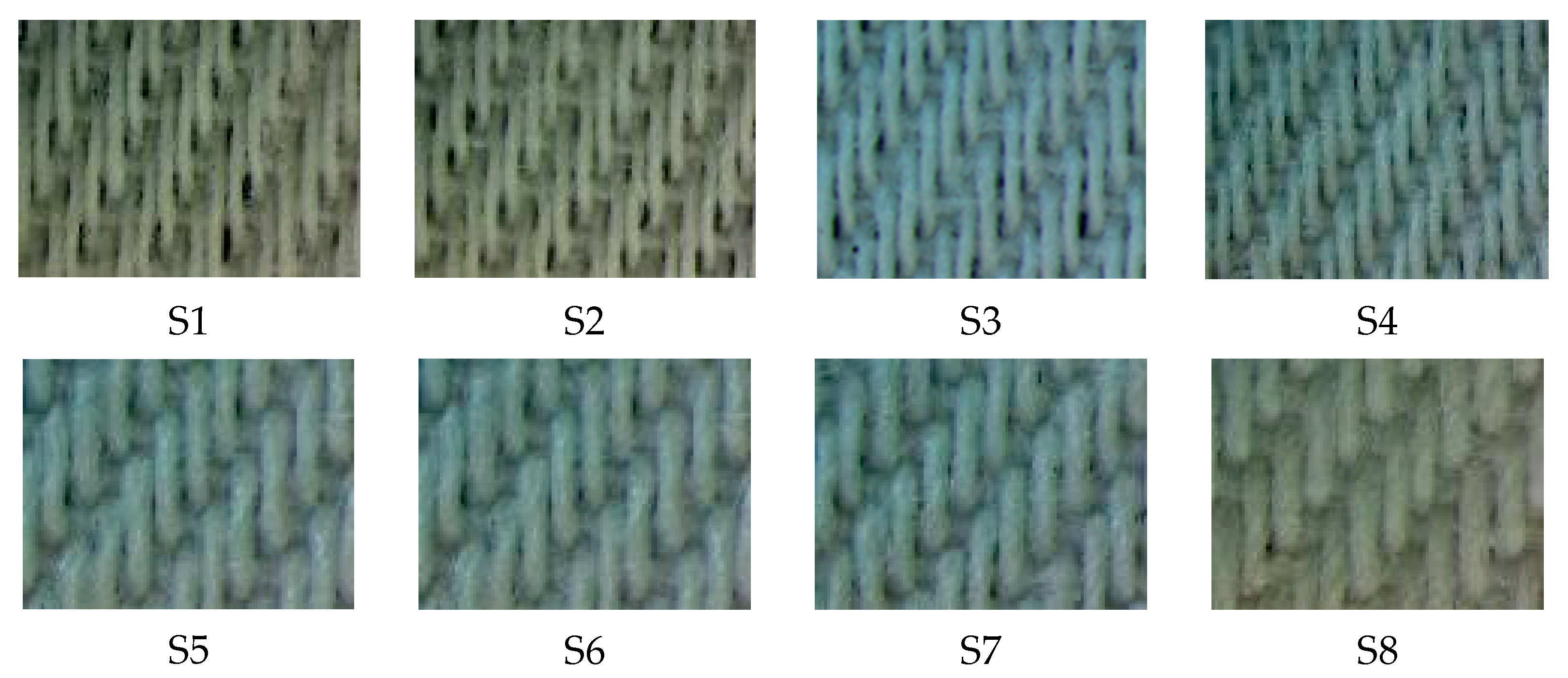
2.1. Material and Structure of Woven Fabrics

The material of woven fabrics consists of two yarns. The first yarn is the weft yarn, in the x-direction (horizontal), and the second is the warp yarn, in the y-direction (vertical). In the x-direction, the number of weft yarns determines the length of woven fabric, while in the y-direction, the number of warp yarns determines the width of woven fabric. In this study, the material for weft and warp yarns is TR Ne1 20. The TR yarn is a blended fiber consisting of polyester (65%) and rayon (35%).
As shown in Figure 1, the woven structures are twill 3/1, indicating that the warp yarn floats over 3 weft yarn and then floats under 1 weft yarn. These yarns interlace and float with each other, creating minute holes that are more manageable, and a stronger structure can be expected. Therefore, a weaving machine can adjust the size and the form of holes in woven fabrics. It should be noted that the variation of perforation parameters cannot be determined in an exact factor number, as a consequence of TR yarn size, while the warp density is kept constant.

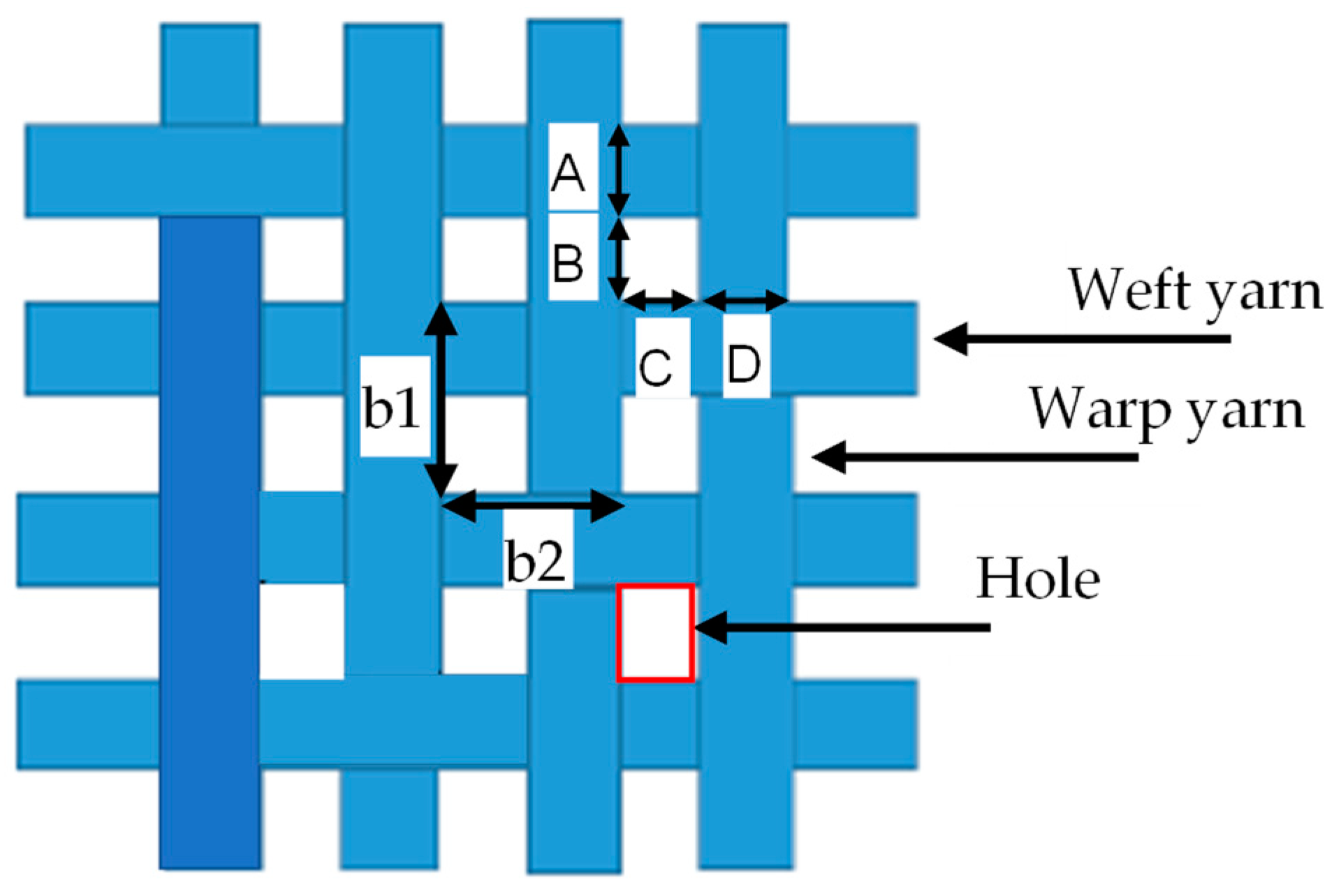
2.2. Textile Parameters and Perforation Properties

To adapt with the twill 3/1 structure, a geometrical hole is defined as indicated in Figure 2. The nominal diameter of hole d and perforation ratio σ of woven fabrics are defined as follows:
d = 2 B C π
b = b 1 + b 2 2 = ( C + D ) + ( A + B ) 2
σ = π 4 d b 2
The hole size of woven fabrics is realized by adjusting the weft or warp density. The weft density defines the number of weft yarns, in cm, and it changes the density in the x-direction, while the warp density defines the number of warp yarns, in cm, and it changes the density in the y-direction. For this study, the warp density was set to 39 yarns/cm, and the weft density was varied from 14 to 28 yarns/cm with an increment of 2 yarns/cm. All variations were realized in the weaving machine. Eight samples were produced and designated as S1, S2, and so on, as listed in Table 1.

2.3. Yarns Properties and MPP Structure

The fibers of polyester and rayon in yarn TR Ne1 20 are twisted into each other to render yarns that are coherent, compact, and dense components. Hence, the yarn can be considered a solid surface. The actual woven fabric consists of micro-holes and non-hole parts, as seen in Figure 3. The non-hole parts are created by yarns, while the micro-hole parts are a result of warp and weft adjustment. This situation brings some consequences: (1) The non-hole parts have a high impedance, so that it is considered as a solid surface; (2) Hole parts are responsible for the absorption mechanism. Such a surface property is considered to be an acceptable best approximation to satisfy microperforated panel (MPP) requirements.
As shown in Figure 4, the MPP woven fabric-based system is realized by placing woven fabric in front of the air cavity layer, where a specification of woven fabrics is described in Table 1. In this study, the air cavity depth between the woven fabric and the impervious layer is set to 15 mm.

3. Methods

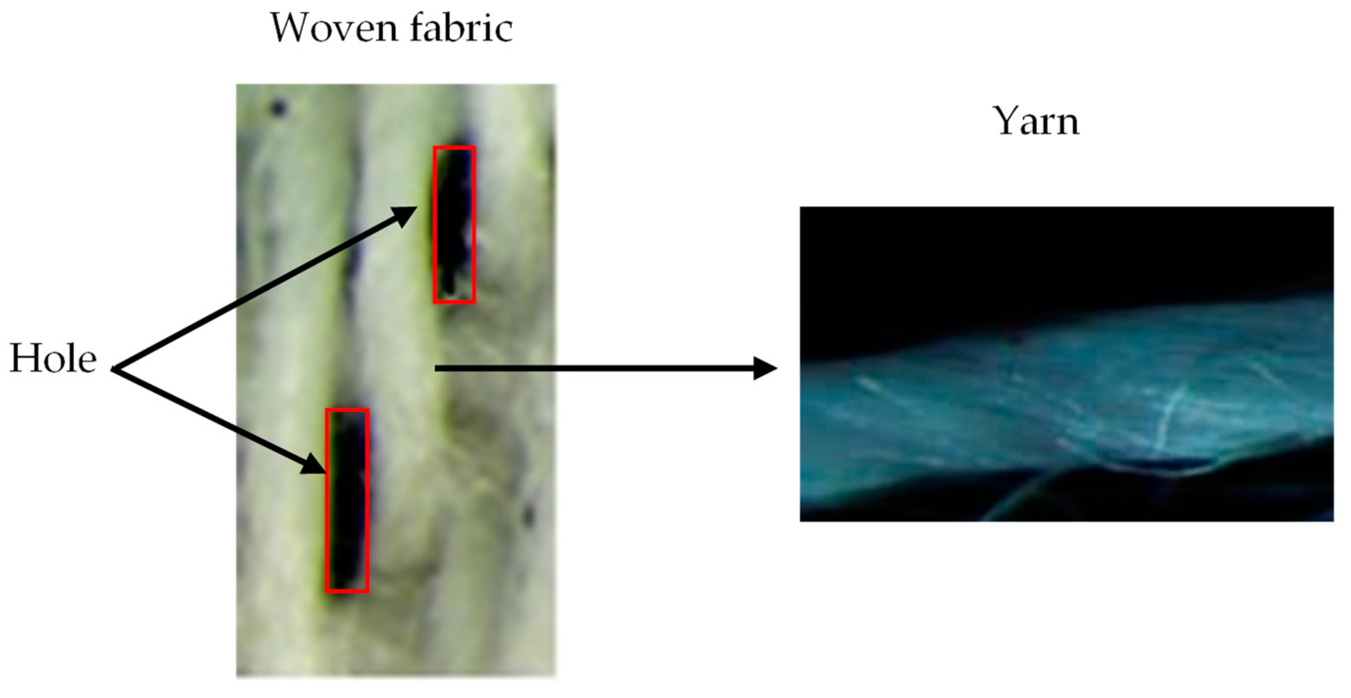
3.1. Geometrical Characterization

The thickness of woven fabric was measured by a fabric thickness tester (Teclock) according to ISO 5084:1996 [30]. It was found that the thickness was equal to 0.5 mm. Meanwhile, the geometrical properties were characterized using a digital microscope, and the samples were taken from 10 different areas so that the results were statistically averaged. Figure 5 shows a magnification image sample of woven fabric taken with a digital microscope. In this study, hole diameter d is determined from hypothetical rectangular holes, where Equation (1) was used to obtain the hole diameter by which the equivalent area principle is employed. Likewise, the pitch b is the average of b 1   and b 2 .

3.2. Flow Resistance Measurement

Flow resistance is an important parameter affecting sound absorption behavior. In this study, the flow resistance R s was estimated from the measurement of air permeability of textiles using the following equation [31]:
R s = Δ p . A f .1002 Q . A p ,
where A f is the fabric area tested for specific airflow resistance (cm2), Δ p is the pressure drop (Pa) which is nominally set to 200 Pa in this measurement, Q is the air permeability (mm/s), and A p is the cross-sectional area of fabric in the test of air permeability (cm2), which is nominally set to 20 cm2. The air permeability was measured using Testex instruments according to ISO 9237.

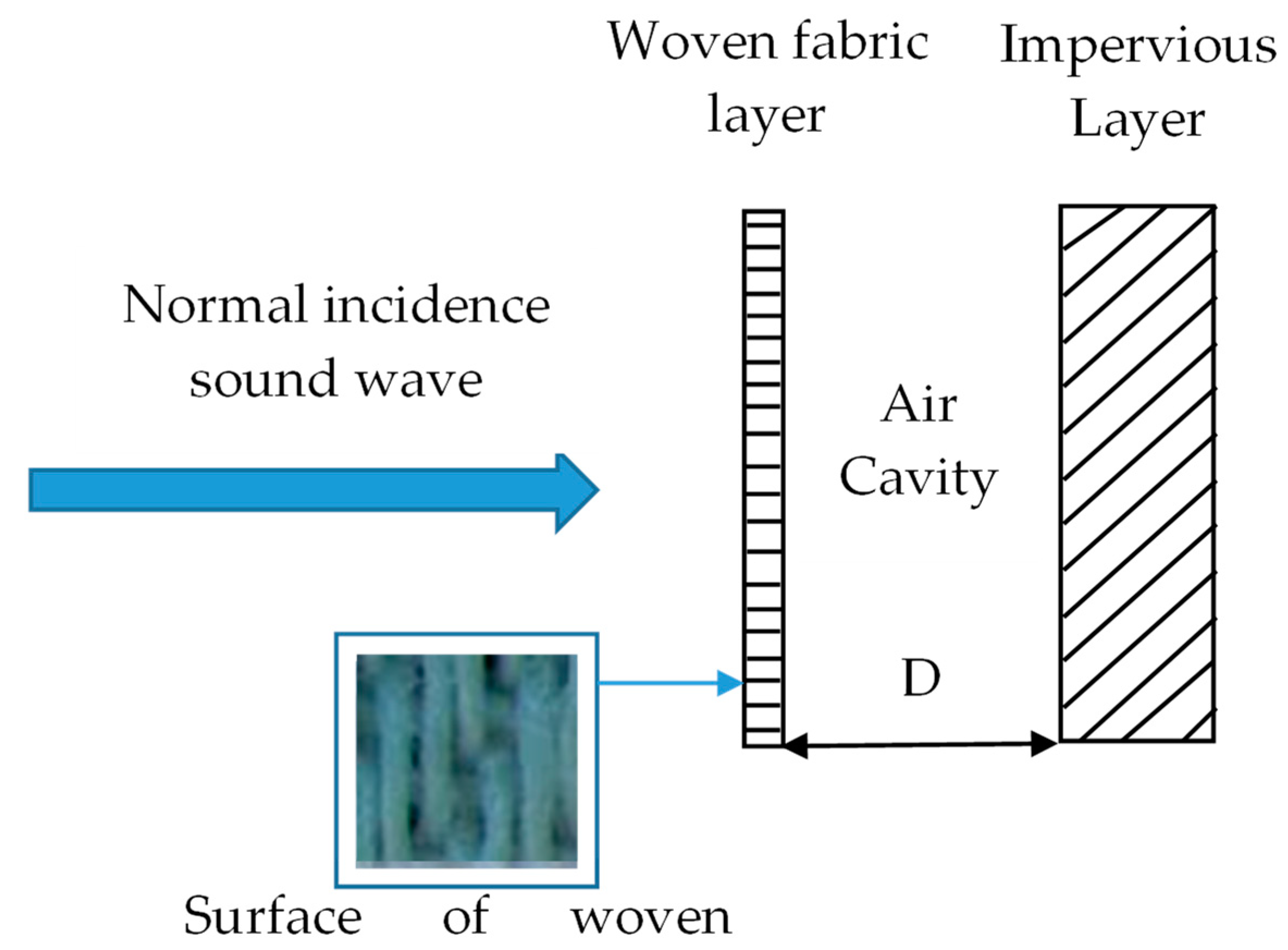
3.3. Acoustic Characterization

Normal sound absorption coefficients of each woven fabric sample were measured by an impedance tube using the transfer function method according to ISO 10534-2 [32]. During the measurement, a white noise source was produced inside the tube to produce plane waves through a 3 cm and 10 cm diameter tube to cover 64 Hz to 6 kHz. The traveling plane wave through the tube is recorded by two-spaced acoustic microphones. Moreover, a special holder was designed using acrylic to hold the woven fabric as rigidly as possible along its perimeter. The holder needs to be carefully designed in order to properly allow for the stretching of the fabric while preventing air leakage between the main tube and the backing tube. Figure 6 shows the schematic diagram, the absorption coefficient measurement, and other relevant acoustic parameters of an impedance tube where the air cavity was set to 15 mm for all woven fabric samples and 0–30 mm for sample S8.

4. Results and Discussions

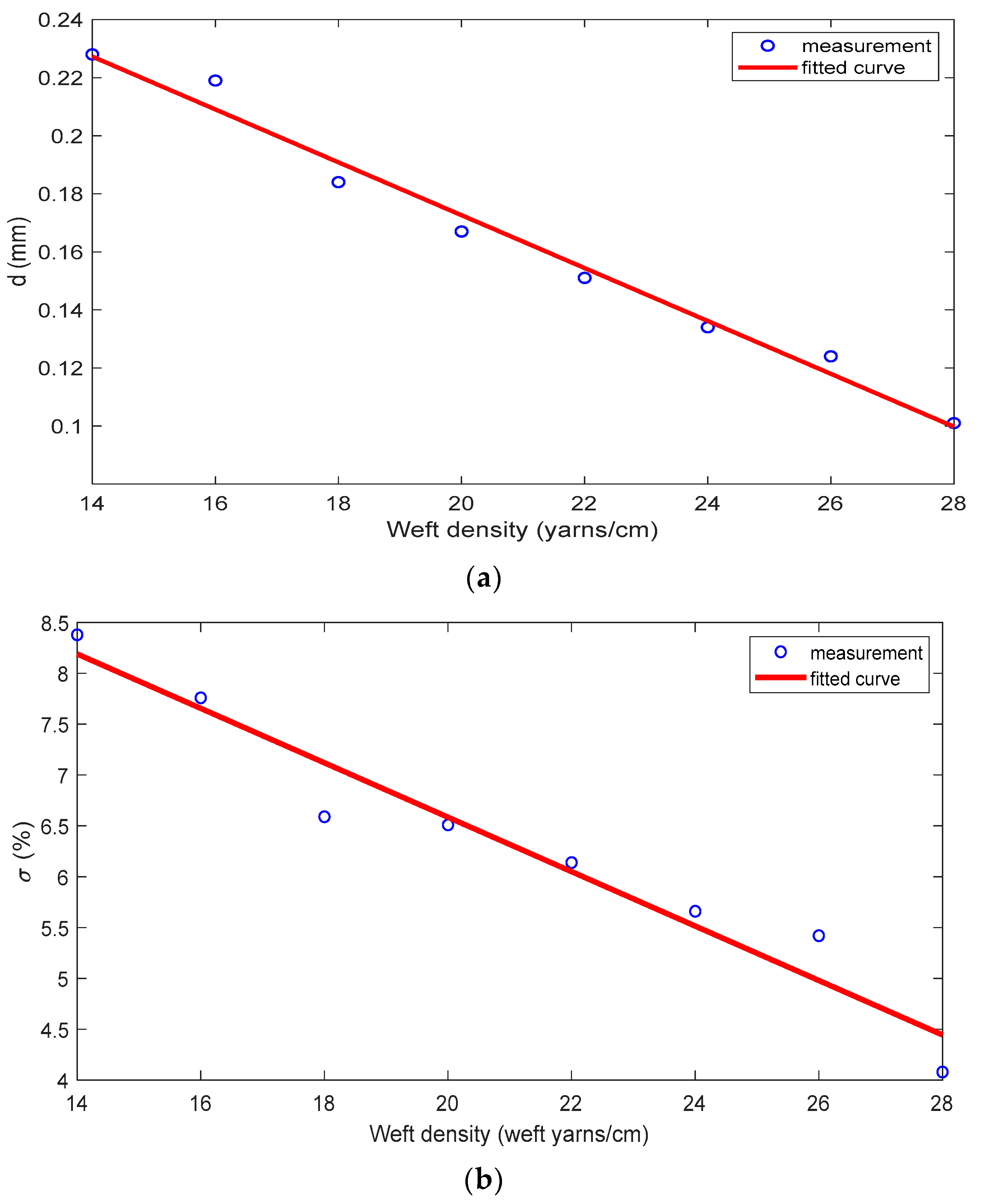
4.1. Relationship of Weft Density and Hole Diameter

Table 2 lists the resulting hole diameters and perforation ratios for all woven fabrics. From this, the linear regression fitting between the weft density X and the hole diameter is: d =   0.008399 X + 0.338 , with R 2 = 0.99 as shown in Figure 7a. The R-square value suggests that adjusting the weft density to the associated hole diameter displays linear characteristics that are useful from a practical point of view, and increasing the weft density can lead to a smaller hole diameter. Similarly, the relationship of the perforation ratio and the weft density is shown in Figure 7b, where it is found that σ = 0.2235 X + 10.97 , with R 2 = 0.92 . Such relationships are useful for woven-fabric fabrication that is designed specifically to be a sound absorber. In this study, the smallest hole diameter of 0.103 mm has been successfully fabricated with σ of 4.25%, obtained by the use of a weft density of 28 yarns/cm.

4.2. Flow Resistance Characteristics

Table 3 shows the flow resistance of all samples. It can be seen that the air permeability and airflow resistance of the woven fabric is a function of the hole diameter d. It is clear that higher airflow resistance and lower air permeability are present as the hole diameter increases. Such behavior is consistent considering Equation (4). It can be seen that the air permeability is inversely proportional to the airflow resistance.
Compared with textile membranes, the hole diameters of the samples are much bigger where the membrane hole diameter is in micron-scale, around 0.03 μm to 10 μm [33,34], and therefore the air permeability of such a material is lower; around 1–58 cc/cm2/s, air permeability is non-existent [35]. Moreover, coating treatments based on polymers such as PVC, PTFE, ETFE, Silicone, and PU [36,37,38,39] are required to form a membrane in textiles. This fact indicates that the samples used in this study should not be considered as membranes. Hence, the absorption mechanism found in this study is expected as a result of the existing holes on the surface rather than owing to other possible mechanisms.

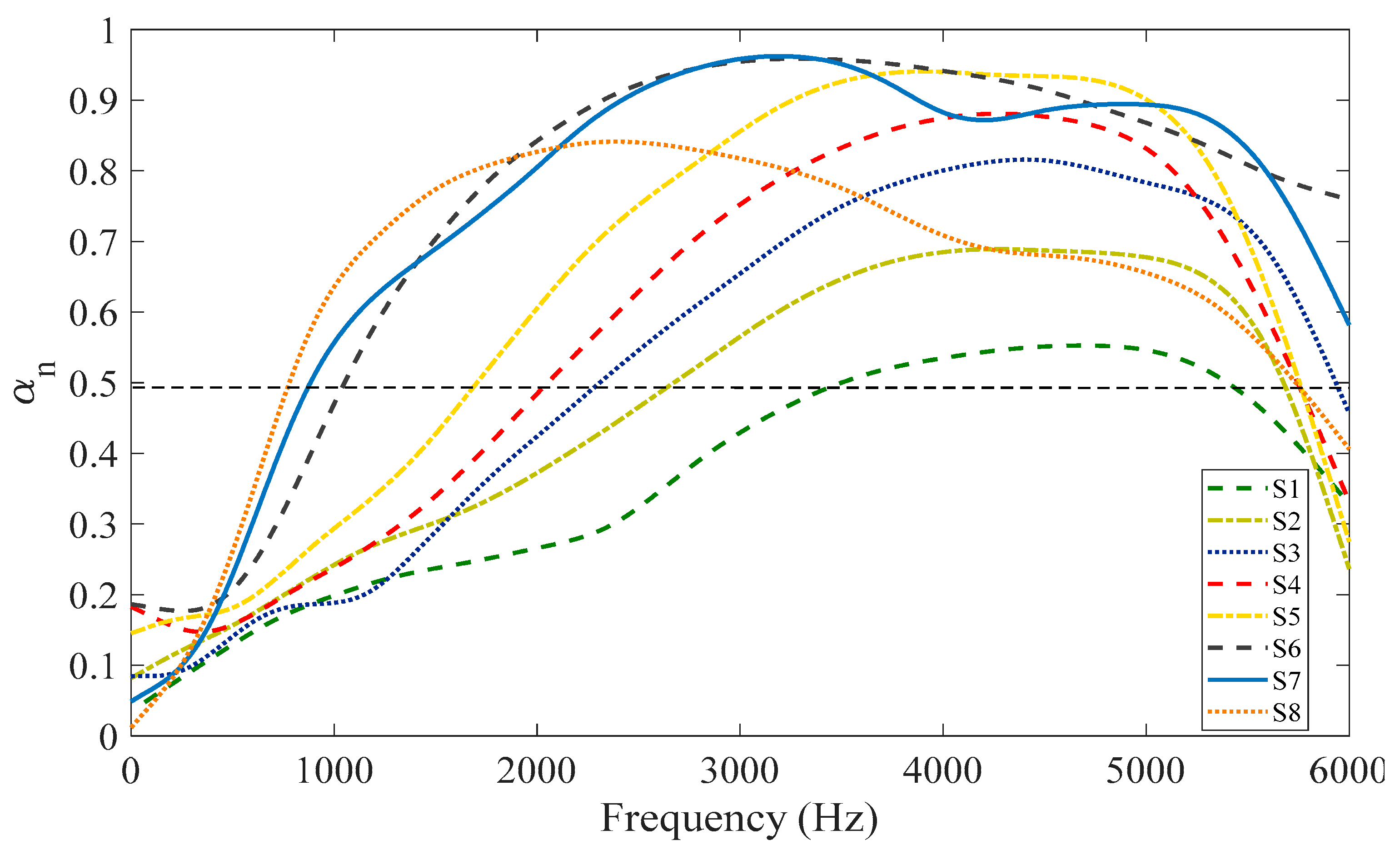
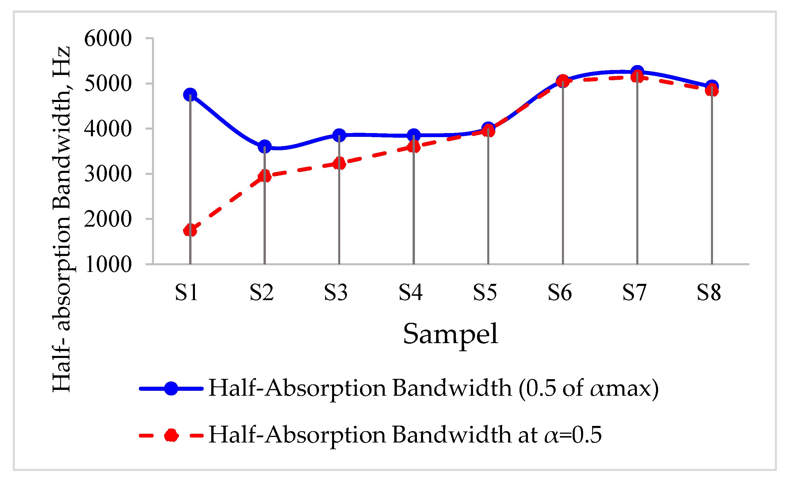
4.3. Absorption Characteristics

4.3.1. Perforation Variation

Figure 8 shows sound absorption coefficients of all woven fabric samples. The absorption coefficient spectrums and associated bandwidths of S1 to S8 are gradually changed; the peak sound absorption coefficient and the absorption bandwidth increase as the hole diameter decreases, and vice versa. From Table 4, it can be seen that the reduction in the hole diameter results in the increase of the peak sound absorption coefficient (αn). The bigger hole diameter S1 = 0.218 mm has the peak acoustic absorption coefficient 0.55, while the smaller hole diameter S8 = 0.103 mm produces the peak acoustic absorption coefficient 0,86. In general, reducing the hole diameter further can lead to the reduction in the peak of sound absorption coefficient α, as a very high resistance can be pronounced and can cause reflection rather than allowing the wave to penetrate the holes. Such behavior can be seen in the woven fabrics S6, S7, and S8. The woven fabrics S6 and S7 have a hole diameter of 0.135 mm and 0.121 mm, respectively, which is greater than S8 with a hole diameter of 0.103 mm, but the peak of the absorption coefficients of S6 and S7 are greater than that of S8. It is clear that the woven fabric S7 is outperformed by the woven fabric sample S8 even though S8 has the smallest hole diameter. Similarly, the absorption coefficient of S6 is also better than that of S8. Such behavior will be later discussed in the context of impedance behavior in Section 4.3.2.
In corresponding to half-absorption bandwidth Δα0.5, where the bandwidth is evaluated at α equal to half of the maximum absorption coefficient, the resulting bandwidth is in the range of 3000 Hz–5000 Hz as recorded in Table 4. The reduction in hole diameter can produce a wider absorption bandwidth. By using different definitions, where half- absorption bandwidth is determined at α   = 0.5, it can be seen that S1 has the half-absorption bandwidth of around 1750 Hz and that increases to 5150 Hz, as indicated by S7. The value is slightly lower for S8, where the half-absorption bandwidth is found at around 4850 Hz. The results also indicate that there is an optimum value of hole diameter for the same air cavity depth. Moreover, the absorption bandwidth produced by the minute holes of woven fabrics can be greater than three octaves, as demonstrated by the woven fabrics S6 and S7.
It is evident that the absorption bandwidth increases as the hole diameter decreases. Such a tendency can be seen in Figure 9, where the half-absorption bandwidths as per definition (a) and (b) in Table 4 are compared for all samples. The half-absorption bandwidth Δα0.5 (see Definition (a)) suggests the absorption bandwidth exists on a narrow absorption bandwidth range, and it is relatively constant for a slightly different hole diameter e.g., S3 and S4; S6 and S7. Meanwhile, the half-absorption bandwidth evaluated at α = 0.5 (see the definition (b)) presents a wide absorption bandwidth range, but it is more consistent to capture an acceptable absorption capability as well as a wider bandwidth of absorber. From now on, most of the discussion in this paper is carried out based on definition (b).
It is instructive to evaluate the improvement attained by comparing the performance of each sample to the other samples, where the sample S1 is chosen as a basis, as indicated by Table 5. Interestingly, reducing the hole diameter of 0.218 mm by 0.097 mm can increase the peak sound absorption coefficient up to 78%, while the half-absorption bandwidth Δα0.5 is almost doubled, up to 194%. This can be beneficial as a reference for the development of acoustic absorbers based on woven fabrics.

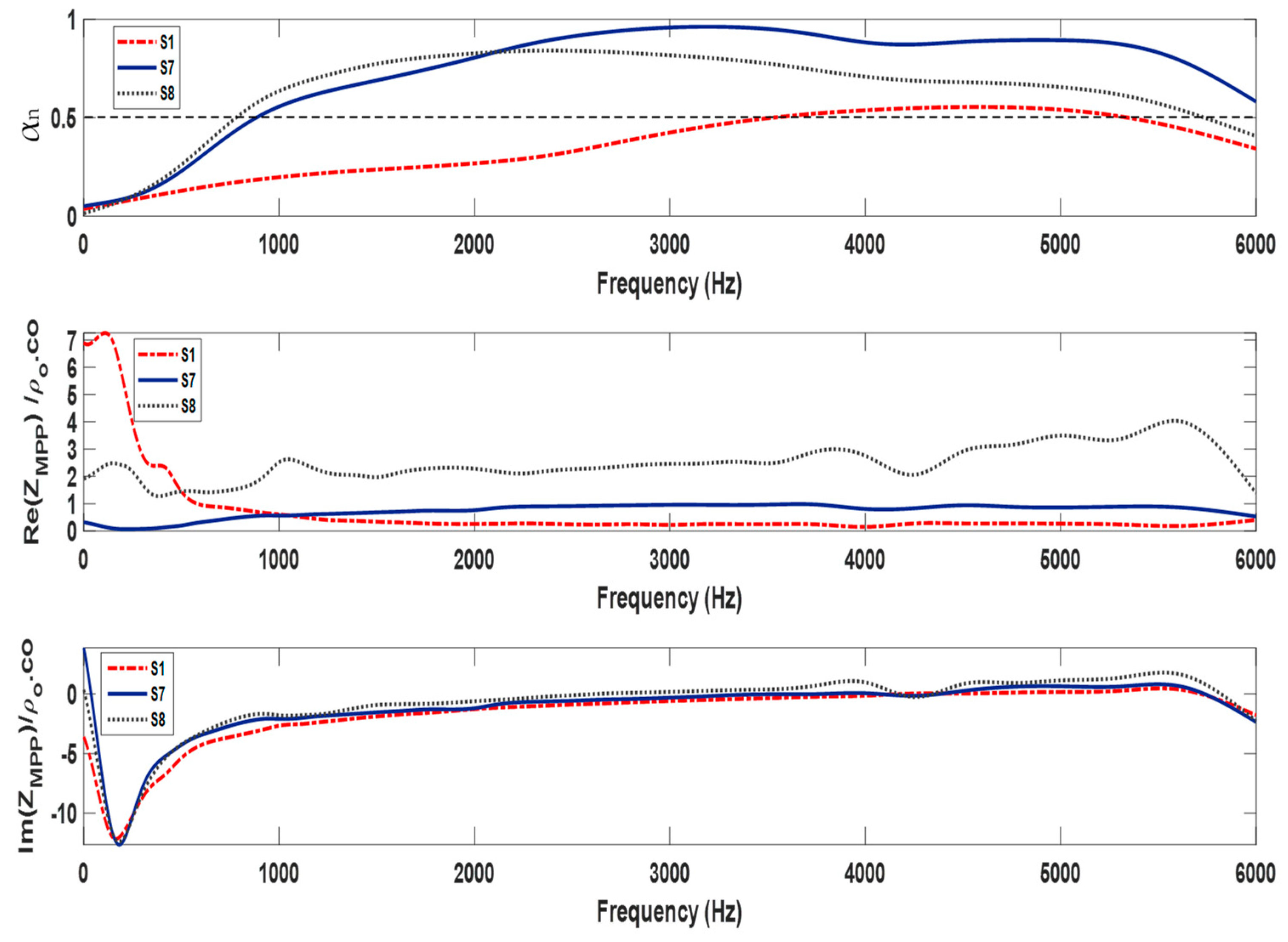
4.3.2. Surface Impedance Behavior

To further discuss the results in Section 4.3.1, the behavior of the surface impedance Z ˜ M P P   obtained from the experimental works are presented in terms of the resistive part, or Re Z ˜ M P P , and the reactive part of Z ˜ M P P or Im Z ˜ M P P , and the associated absorption coefficients for the selected woven fabrics are presented in Figure 10. The woven fabrics S1 and S7 are selected to represent the worst and the best sound absorption coefficients (α) and half-absorption bandwidths (Δα0.5). Meanwhile, the woven fabrics S1 and S8 represent the biggest and the smallest hole diameters of the fabrics.
Overall, there is a significant difference between the peak sound absorption coefficient (α) and the half-absorption bandwidth (Δα0.5) of woven fabric S7 and that of S1. The woven fabric S7 outperformed other sample specifications with a peak α = 0.98, while woven fabric S1 is 0.55. It can be observed that Re Z ˜ M P P of the woven fabric S7 is close to 1 at a frequency of 3750 Hz. This is not the case for the woven fabric S1, where Re Z ˜ M P P is 0.21 at a frequency of 4500 Hz. Apart from that, Im Z ˜ M P P of both woven fabrics is equal to zero at the corresponding peak absorption frequency, as expected. Meanwhile, the behavior of woven fabric S8 is in between the woven fabrics S7 and S1. This tendency can confirm the results where greater resistance leads to better absorptions. This description can become a general explanation for the other woven fabric samples.
The half-absorption bandwidth of woven fabric S7 is 5150 Hz, starting from 850 Hz to 6000 Hz, while that of woven fabric S1 is 1750 Hz, starting at 3550 Hz up to 5300 Hz. Meanwhile, the half-absorption bandwidth of the woven fabric S8 is slightly narrower than that of the woven fabric S7. Hence, the woven fabric S7 is also superior to the woven fabric S1 for this parameter. Such a behavior can be verified by observing resistance behavior at that frequency range where Re Z ˜ M P P of the woven fabric S7 is around 1, while that of the woven fabric S8 is above 1. By contrast, that of the woven fabric S1 is around 0.2. Moreover, the reactance part of both woven fabrics is zero for the corresponding resistance.
Considering the hole diameter of woven fabric S8 is the smallest among the others, the resistance is the highest for a similar perforation ratio so that a better performance is expected. However, it can be seen that its performance is not necessarily outperformed by the other woven fabrics. This suggests that the resistive value is required to be 1, while lower or greater values are not advisable. Moreover, the value of Re Z ˜ M P P greater than 1, as demonstrated by the woven fabric S8, around 1.5–4, is still preferable to a value of Re Z ˜ M P P close to 0. To sum up the discussion, the target of hole diameter and perforation ratio should consider the behavior of resistance and the reactance of impedance to ensure that the absorption performance and associated half absorption bandwidth can satisfy a particular requirement; textile fabrication techniques allow us to form a small hole diameter, but this is not always beneficial considering the relationship of pore geometry and acoustic impedance.

5. Comparison with Existing Theory

5.1. Absorption Mechanism

Micro-perforated panel absorption is present owing to the visco-thermal effect of a tiny hole (d < 1 mm), which is formulated as a short tube. By the array of the tiny holes and the backing by air cavity, the resulting acoustic resistance effect on the maximum particle velocity can be obtained. Hence, the presence of perforation is compulsory to ensure absorption capability is present. As mentioned in the previous section, such a requirement can be observed from woven fabrics where solid parts and holes exist on a thin surface. When reducing holes further to a very tiny dimension, by which the associated resistance of hole becomes large, reflection behavior becomes dominant. Considering the thin surface of the woven fabric, such a material can evolve into a membrane where absorption characteristics are also pronounced under the same structural configuration. For the membrane case, sound absorption can be produced due to losses on both the front and rear surfaces, and even from the back wall surfaces. Although both materials can display absorption characteristics when interacting with incoming sound, the absorption is present due to different requirements where visco-thermal layers in holes and around the surface are compulsory, while that of the membrane is not. From a textile point of view, pore dimension can determine whether the material is a class of fabric or membrane. This can be further verified by an air permeability value in the range of 222.1 mm/s to 1878 mm/s.
A variation on perforation parameter and backing air cavity depth is required to change the absorption behavior of MPP, and those aspects are validated further by Maa’s model in this section. Meanwhile, the change of surface density, stiffness, loss factor, and backing air cavity depth can determine membrane absorption behavior where a thin panel or similar theoretical approach is applicable for such a case.

5.2. Theoretical Model

To verify the absorption behavior of the woven fabric under consideration, Maa’s formulation [7] is employed, which is an approximate model for MPP based on the basic model of Raleigh [40] and Crandall [41]. For normal incidence, the wave motion in all the short tubes can be regarded as being in phase and additive. Therefore, surface acoustic impedance with inclusion of the end correction as proposed by Morse and Ingard [42]. This yields [6]:
Z = Z r + j Z i m = 32 η t σ ρ 0 c d 2 1 + k 2 32 1 / 2 + 2 32 k d t + j ω t σ c 1 + 1 + k 2 2 1 / 2 + 0.85 d t
The perforation constant k = d ω ρ 0 / 4 η , where d is the perforation diameter, ω is the angular frequency, ρ 0 is the air density, and η is the coefficient of fluid viscosity and the perforation ratio area with circular cross-section σ = ( π / 4 ) d / b 2 , where b is the center-to-center distance between holes. This model is applicable under the following conditions: (1) the perforation ratio area is less than 10%; (2) hole interactions are not allowed; and (3) the panels are acoustically rigid. Considering the material and morphology properties of woven fabrics, such conditions may not be satisfied.
To be effective in the absorption process, the MPP absorbers require a backing air cavity with cavity depth   D . Together with   Z r , it is required to tune its absorption at a resonance frequency f 0 at which the maximum absorption can be obtained. The combined surface impedance of the MPP and the air in the cavity Z M P P is thus given by:
Z M P P = Z + Z c a v
where:
Z c a v = j cot ω D c 0
The sound absorption coefficient for normal incidence is thus defined as:
α n = 4 Z r ( 1 + Z r ) 2 + ( Z i m cot ω D / c ) 2
and the maximum coefficient is given by:
α max = 4 Z r ( 1 + Z r ) 2
For α = 0.5 (half absorption) of the maximum absorption in Equation (10), the following expression exists:
( 1 + Z r ) 2 + ( Z i m cot ω D / c ) 2 ( 1 + Z r ) 2 = 2
Hence, the associated bandwidth can be determined by:
Z i m cot ω D c 0 = ± ( 1 + Z r )
Considering ω D / c 0 in Equation (12) is proportional to frequency so that the ±   sign indicates the lower and upper half-absorption points. For a wider absorption bandwidth, smaller Z i m and larger Z r are required. Such behavior is evident in the surface impedance behavior, as presented in Section 4.3.2.
In the next section, validation results are presented. The root mean squared error (RMSE) is then used to evaluate two result differences and is expressed as follows:
R M S E = 1 n i = 1 n α i α ˜ i 2
where α i is the measured absorption coefficient, α ˜ i is the predicted absorption coefficient by Maa’s model, and n is the number of data.

5.3. Validation Results

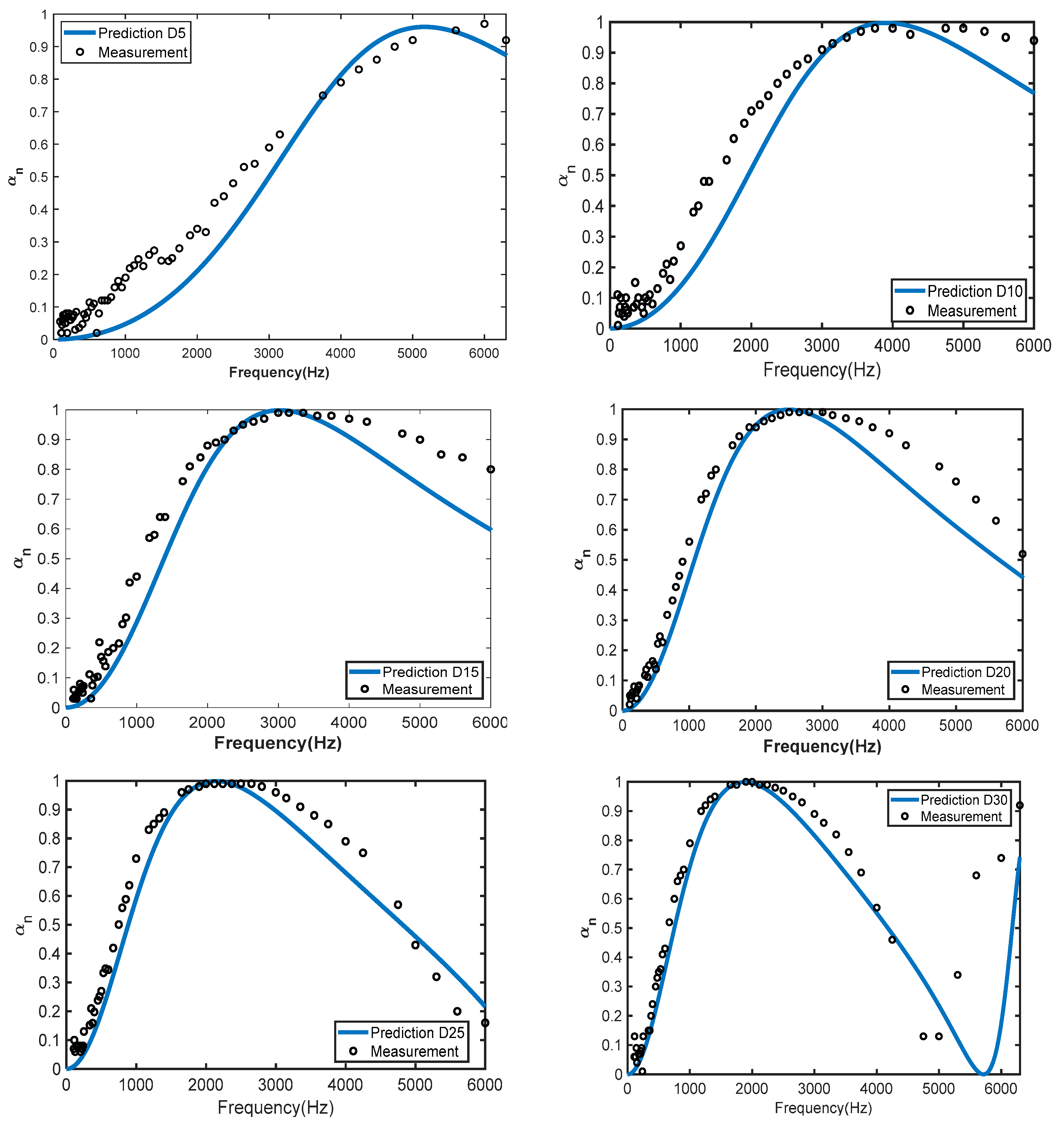
5.3.1. Effect of Backing Air Cavity Depth

According to Equation (6), it can be seen that impedance of MPP Z M P P is a combination of surface impedance and backing air cavity depth. The impedance of the backing air cavity depth governs the mechanism of sound absorption, as seen in Equation (7). In order to observe the sound absorption behavior of woven fabric as an MPP absorber, the sample S7, with a variation in air cavity depth of 5–30 mm with an increment of 5 mm, designated as D5, D10, D15, and so on, is validated using Maa’s model.
Figure 11 shows the sound absorption for variations of the air cavity depth D. It can be observed from both experimental and theoretical results that the absorption peak shifts to a lower frequency, as expected, as the backing air cavity depth increases. Moreover, both results are in good agreement. Although Maa’s model can predict the behavior of the absorption coefficient, there are deviations. As can be seen in Table 6, RMSE values are around 0.07–0.17. For the woven fabric D5 and D10, with RMSE of 0.17 and 0.10, the model prediction underestimates the measurement at the middle frequency (f < 3000 Hz). The deviations can be expected coming from the use of average empirical values for hole diameter d in Equation (1) and perforation ratio σ in Equation (3), which were estimated from measurements.

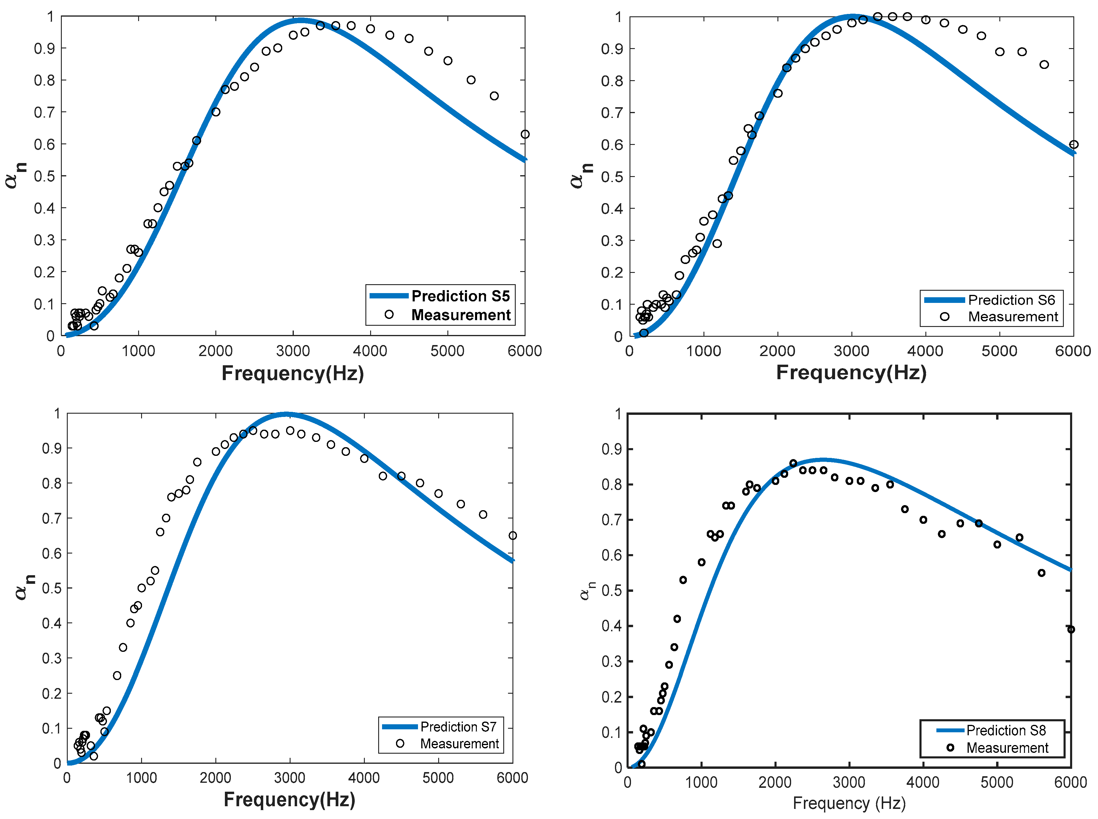
5.3.2. Effect of perforation ratio

The hole diameter d and perforation ratio σ for all cases are taken from Table 2. Meanwhile, the air properties used in the Maa’s model are co = 340 m/s, ρo = 1.21 kg/m3, η   = 1.79 × 10⁻⁵ kg/ms, and air cavity depth D = 15 mm.
It can be seen from Figure 12 that the experimental results and Maa’s model share common features where the behavior of the absorption coefficient is similar. Such an indication is evident from the RMSE values found around 0.05–0.11, as listed in Table 7. This result shows that the behavior of woven fabric follows the typical behavior of an MPP absorber. Apart from this, the Maa’s model is also applicable to MPPs based on woven fabric material.
Although the trend of the absorption coefficient can be predicted by Maa’s model, there are deviations between the model and measurement, particularly at frequency above the resonance absorption. This can be attributed to the shape factor, as suggested from some references [26,43]. For the woven fabric S3–S6, with RMSE of 0.07–0.10, the model prediction underestimates the measurement at high frequencies (f > 4000 Hz). The deviations can be expected to come from the use of average empirical values for hole diameter d in Equation (1) and perforation ratio σ in Equation (3), which were estimated from measurements.

6. Conclusions

This paper has investigated minute holes in woven fabrics for a wideband MPP absorber and the associated absorption behavior has been discussed. Micro-perforation woven fabrics with diameters of 0.103 mm–0.218 mm have been fabricated in woven fabric by varying the density of the weft yarn while the warp yarns remain. Hence, a weft density is useful to control the hole diameter and perforation ratio. Half-absorption bandwidth Δα0.5 can be more than 3 octaves while a peak of the absorption coefficient of greater than 0.8 is present. Such absorption bandwidth is greater than the one to two octaves typically found in conventional MPP, so the wideband absorption requirement can be satisfied. However, a smaller hole diameter cannot be a guarantee to obtain the higher half-absorption bandwidth Δα0.5 and the peak of the sound absorption coefficient αmax. Moreover, a very small difference on the order of 10−2 mm in hole diameter can change absorption behavior. This is related to the behavior of resistance and reactance of impedance of woven fabric, which should be carefully determined to obtain a higher half-absorption bandwidth Δα0.5 and peak of sound absorption coefficient αmax. From this study, it is also evident that the behavior of the sound absorption coefficient of woven fabric is similar to results produced by Maa’s model for a particular frequency range, with RMSE around 0.10–0.17. The behavior of woven fabric also follows Maa’s model as the air cavity depth was varied. This suggests that woven fabrics can be an alternative approach to obtain minute holes, while Maa’s model is applicable to predict its absorption characteristics.

Author Contributions

Conceptualization, G. and I.P.; methodology, G.; software, G. and I.P.; validation, G. and I.P.; formal analysis, I.P., B.Y. and A.P.; resources, I.; data curation, G. and I.; writing—original draft preparation, G. and I.P.; writing—review and editing, I.P. and A.P.; project administration, I.P.; funding acquisition, I.P. and B.Y. All authors have read and agreed to the published version of the manuscript.

Funding

This work was funded by Institut Teknologi Bandung research grant No. 0109/I1.B04.1/PL.

Data Availability Statement

Not applicable.

Conflicts of Interest

The authors have no competing interest to declare that are relevant to the content of this article.

References

  1. Fuchs, H.V.; Zha, X. Acrylic-glass sound absorbers in the plenum of the deutscher bundestag. Appl. Acoust. 1997, 51, 211–217. [Google Scholar] [CrossRef]
  2. Sarwono, J.; Prasetiyo, I.; Andreas, S.; William, A. The Design of MPP and its Application to Enhance the Acoustics of a Real Auditorium. In Proceedings of the INTER-NOISE and NOISE-CON Congress and Conference Proceedings Internoise, Melbourne, Australia, 16–19 November 2014. [Google Scholar]
  3. Hoshi, K.; Hanyu, T.; Okuzono, T.; Sakagami, K.; Yairi, M.; Harada, S.; Takahashi, S.; Ueda, Y. Implementation experiment of a honeycomb backed MPP sound absorbing panel in a meeting room. In Proceedings of the 25th International Congress on Sound and Vibration, Hiroshima, Japan, 8–12 July 2018. [Google Scholar]
  4. Liu, J.; Herrin, D.W.; Seybert, A.F. Application of Micro-Perforated Panels to Attenuate Noise in a Duct; SAE: Warrendale, PA, USA, 2007. [Google Scholar]
  5. Cobo, P.; Ruiz, H.; Alvarez, J. Double-Layer Microperforated Panel/Porous Absorber as Liner for Anechoic Closing of the Test Section in Wind Tunnels. Acta Acust. United Acust. 2010, 96, 914–922. [Google Scholar] [CrossRef] [Green Version]
  6. Maa, D.-Y. Potential of microperforated panel absorber. J. Acoust. Soc. Am. 1998, 104, 2861. [Google Scholar] [CrossRef]
  7. Maa, D.-Y. Microperforated Panel Wideband Absrbers. Noise Control. Eng. J. 1987, 29, 3. [Google Scholar] [CrossRef]
  8. Li, X.; Wu, Q.; Kang, L.; Liu, B. Design of Multiple Parallel-Arranged Perforated Panel Absorbers for Low Frequency Sound Absorption. Materials 2019, 12, 2099. [Google Scholar] [CrossRef] [Green Version]
  9. Verdière, K.; Panneton, R.; Elkoun, S.; Dupont, T.; Leclaire, P. Prediction of acoustic properties of parallel assemblies by means of transfer matrix method. Proc. Mtgs. Acoust. 2013, 19, 065011. [Google Scholar] [CrossRef]
  10. Qian, Y.J.; Zhang, J.; Sun, N.; Kong, D.Y.; Zhang, X.X. Pilot study on wideband sound absorber obtained by adopting a serial-parallel coupling manner. Appl. Acoust. 2017, 124, 48–51. [Google Scholar] [CrossRef]
  11. Sakagami, K.; Kobatake, S.; Kano, K.I.; Morimoto, M.; Yairi, M. Sound absorption characteristics of a single microperforated panel absorber backed by a porous absorbent layer. Acoust. Aust. 2011, 39, 95–100. [Google Scholar]
  12. Liu, Z.; Zhan, J.; Fard, M.; Davy, J.L. Acoustic measurement of a 3D printed micro-perforated panel combined with a porous material. Measurement 2017, 104, 233–236. [Google Scholar] [CrossRef]
  13. Yuvaraj, L.; Jeyanthi, S.; Mailan Chinnapandi, L.B. Sound absorption of Multilayer Micro perforated Panel with Helmholtz Resonator Mount. In Proceedings of the INTER-NOISE and NOISE-CON Congress and Conference Proceedings, Madrid, Spain, 16–19 June 2019. [Google Scholar]
  14. Gai, X.-L.; Xing, T.; Cai, Z.-N.; Wang, F.; Li, X.-H.; Zhang, B.; Guan, X.-W. Developing a microperforated panel with ultra-micro holes by heat shrinkable materials. Appl. Acoust. 2019, 152, 47–53. [Google Scholar] [CrossRef]
  15. Qian, Y.J.; Kong, D.Y.; Liu, S.M.; Sun, S.M.; Zhao, Z. Investigation on micro-perforated panel absorber with ultra-micro perforations. Appl. Acoust. 2013, 74, 931–935. [Google Scholar] [CrossRef]
  16. Qian, Y.J.; Kong, D.Y.; Fei, J.T. A note on the fabrication methods of flexible ultra micro-perforated panels. Appl. Acoust. 2015, 90, 138–142. [Google Scholar] [CrossRef]
  17. Cobo, P.; Montero de Espinosa, F. Proposal of cheap microperforated panel absorbers manufactured by infiltration. Appl. Acoust. 2013, 74, 1069–1075. [Google Scholar] [CrossRef]
  18. Qian, Y.J.; Cui, K.; Liu, S.M.; Li, Z.B.; Kong, D.Y.; Sun, S.M. Development of broadband ultra micro-perforated panels based on MEMS technology. Appl. Mech. Mater. 2014, 535, 788–795. [Google Scholar] [CrossRef]
  19. Wu, S.H.; Zhao, Z.; Guo, L.J.; Du, L.D.; Xiao, L.; Fang, Z.; Zhao, J.J.; Xuan, Y.D. Two Fabrication Schematics of Silicon Micro Perforated Panel Based on MEMS Technology. Key Eng. Mater. 2012, 503, 324–328. [Google Scholar] [CrossRef]
  20. Ruiz, H.; Cobo, P.; Dupont, T.; Martin, B.; Leclaire, P. Acoustic properties of plates with unevenly distributed macroperforations backed by woven meshes. J. Acoust. Soc. Am. 2012, 132, 3138–3147. [Google Scholar] [CrossRef] [Green Version]
  21. Tang, X.; Kong, D.; Yan, X. Facile dip-coating method to prepare micro-perforated fabric acoustic absorber. Appl. Acoust. 2018, 130, 133–139. [Google Scholar] [CrossRef]
  22. Tang, X.; Kong, D.; Yan, X. Multiple regression analysis of a woven fabric sound absorber. Text. Res. J. 2018, 89, 855–866. [Google Scholar] [CrossRef]
  23. Pieren, R. Sound absorption modeling of thin woven fabrics backed by an air cavity. Text. Res. J. 2012, 82, 864–874. [Google Scholar] [CrossRef]
  24. Pieren, R.; Heutschi, K. Predicting sound absorption coefficients of lightweight multilayer curtains using the equivalent circuit method. Appl. Acoust. 2015, 92, 27–41. [Google Scholar] [CrossRef]
  25. Pieren, R.; Schäffer, B.; Schoenwald, S.; Eggenschwiler, K. Sound absorption of textile curtains—Theoretical models and validations by experiments and simulations. Text. Res. J. 2016, 88, 36–48. [Google Scholar] [CrossRef]
  26. Prasetiyo, I.; Muqowi, E.; Putra, A.; Novenbrianty, M.; Desendra, G.; Adhika, D.R. Modelling sound absorption of tunable double layer woven fabrics. Appl. Acoust. 2020, 157, 107008. [Google Scholar] [CrossRef]
  27. Prasetiyo, I.; Desendra, G.; Hermanto, M.N.; Andhika, D.R. On Woven Fabric Sound Absorption Prediction. Arch. Acoust. 2018, 43, 707–715. [Google Scholar] [CrossRef]
  28. Onursal, O.; Mehmet, C. Design of a single layer micro-perforated sound absorber by finite element analysis. Appl. Acoust. 2010, 71, 79–85. [Google Scholar]
  29. Desendra, G.; Prasetiyo, I.; Hermanto, M.N.; Andhika, D.R. Experimental investigation of fabric-based micro perforated panel absorber. In Proceedings of the Regional Conference on Acoustics and Vibration 2017 (RECAV 2017), Bali, Indonesia, 27–28 November 2017. [Google Scholar]
  30. ISO 5084; Textiles—Determination of Thickness of Textiles and Textiles Products. ISO: Geneva, Switzerland, 1996.
  31. Tang, X.; Jeong, C.-H.; Yan, X. Prediction of sound absorption based on specific airflow resistance and air permeability of textiles. J. Acoust. Soc. Am. 2018, 144, EL100–EL104. [Google Scholar] [CrossRef] [Green Version]
  32. ISO 10534-2; Acoustics—Determination of Sound Absorption Coefficient and Impedance in Impedances Tubes. ISO: Geneva, Switzerland, 2001.
  33. Hunter, L.; Fan, J. 11—Waterproofing and breathability of fabrics and garments. In Engineering Apparel Fabrics and Garments; Fan, J., Hunter, L., Eds.; Woodhead Publishing: Cambridge, UK, 2009; pp. 283–308. [Google Scholar] [CrossRef]
  34. Marcinkowska, D.; Kaleta, A. Structure and Properties of Microporous Polyurethane Membranes Designed for Textile-Polymeric Composite Systems. Fibres Text. East. Eur. 2005, 13, 53–58. [Google Scholar]
  35. Kim, J.J.; Jeong, J.H.; Sohn, J.-Y. Sound absorption characteristics of PTFE membrane Material and their application to a multi-purpose stadium. Build. Serv. Eng. Res. Technol. 2009, 30, 213–226. [Google Scholar] [CrossRef]
  36. Razak, H.A.; Chua, C.S.; Toyoda, H. Weatherability of coated fabrics as roofing material in tropical environment. Build. Environ. 2004, 39, 87–92. [Google Scholar] [CrossRef]
  37. Llorens, J.; Zanelli, A. Structural Membranes for Refurbishment of the Architectural Heritage. Procedia Eng. 2016, 155, 18–27. [Google Scholar] [CrossRef] [Green Version]
  38. Chilton, J. 7—Tensile structures—Textiles for architecture and design. In Textiles, Polymers and Composites for Buildings; Pohl, G., Ed.; Woodhead Publishing: Cambridge, UK, 2010; pp. 229–257. [Google Scholar] [CrossRef]
  39. Monjo-Carrió, J.; Tejera, J. 12—The use of textile materials for architectural membranes. In Fibrous and Composite Materials for Civil Engineering Applications; Fangueiro, R., Ed.; Woodhead Publishing: Cambridge, UK, 2011; pp. 325–387. [Google Scholar] [CrossRef]
  40. Raleigh, J. Theory of Sound II; MacMillan: New York, NY, USA, 1929. [Google Scholar]
  41. Crandall, I.B. Theory of Vibration System and Sound; D.Van Nostrand Company: New York, NY, USA, 1926. [Google Scholar]
  42. Morse, P.M.; Ingard, K.U. Theoretical Acoustics; McGraw Hill: New York, NY, USA, 1968. [Google Scholar]
  43. Xu, Z.; He, W.; Peng, X.; Xin, F.; Lu, T.J. Sound absorption theory for micro-perforated panel with petal-shaped perforations. J. Acoust. Soc. Am. 2020, 148, 18–24. [Google Scholar] [CrossRef]
Figure 1. The basic structure of woven fabric with twill 3/1 structure.
Buildings 13 00663 g001
Figure 2. Geometrical hole parameters of twill 3/1 structure.
Buildings 13 00663 g002
Figure 3. The holes and the non-hole parts of woven fabric are formed by the yarns.
Buildings 13 00663 g003
Figure 4. The basic structure of the MPP system considered in this study.
Buildings 13 00663 g004
Figure 5. Magnification of images of eight woven fabric samples with different weft densities. The dark area indicates holes, otherwise the images consist of yarn. The magnification sample S5–S8 is displayed bigger than S1–S4.
Buildings 13 00663 g005
Figure 6. The schematic of measurement setup: (a) impedance tube (b) holder and woven sample.
Buildings 13 00663 g006
Figure 7. (a) Linear regression fitting weft density and hole diameter; (b) Linear regression fitting weft density and perforation ratio.
Buildings 13 00663 g007
Figure 8. The sound absorption coefficient of woven fabric S1–S8 for normal incidence wave.
Buildings 13 00663 g008
Figure 9. The trend of half-absorption bandwidth for different hole diameter and bandwidth comparison between Δ α 0.5 = 0.5 × α m a x   and   α = 0.5 .
Buildings 13 00663 g009
Figure 10. Sound absorption, resistive part, and reactive part of Z ˜ M P P   for woven fabric S1, S7, and S8.
Buildings 13 00663 g010
Figure 11. Sound absorption comparison results between Maa’s model and the measurement results for woven fabric S7 with variation air cavity depth of 5–30 mm (D5–D30).
Buildings 13 00663 g011
Figure 12. Sound absorption comparison results between Maa’s model and the measurement results for woven fabric S1–S8.
Buildings 13 00663 g012aBuildings 13 00663 g012b
Table 1. The warp and weft density of eight woven fabric samples.
Sample (S)Warp Density (yarn/cm)Weft Density (yarn/cm)
S13914
S23916
S33918
S43920
S53922
S63924
S73926
S83928
Table 2. Hole diameter and perforation ratio woven fabrics.
Sample (S)Hole Diameter (d)
(mm)
Perforation Ratio σ (%) (Equation (3))
S10.2187.37
S20.2067.33
S30.1897.16
S40.1706.85
S50.1516.35
S60.1355.74
S70.1215.14
S80.1034.25
Table 3. Measured air flow resistance of eight woven fabrics.
Sample (S)Hole Diameter (d)
(mm)
Air Permeability (mm/s)Airflow Resistance (Pa s/m)
S10.2181878170.7
S20.2061477217.1
S30.1891109289.1
S40.170877.4365.4
S50.151634.4505.4
S60.135434.8737.4
S70.121357.2897.6
S80.103222.11443.7
Table 4. The peaks and absorption bandwidth of each sample.
SamplesThe peak of Sound Absorption Coefficient (αmax)Half-Absorption Bandwidth
Δα0.5, Hz (a)α = 0.5, Hz (b)
S10.5547501750
S20.7036002950
S30.8438503230
S40.8938503600
S50.9540003950
S60.9650505050
S70.9852505150
S80.8649304850
(a) half-absorption bandwidth: Δ α 0.5 = 0.5 × α m a x . Half-absorption bandwidth is evaluated at   α equal to half of the maximum absorption coefficient. (b) half-absorption bandwidth evaluated at α = 0.5 . Half-absorption bandwidth is determined at α   = 0.5.
Table 5. Absorption performance difference between samples.
SamplesDifference of Hole Diameter (mm)Percentage of the Peak Difference of Sound Absorption Coefficient (%)Percentage of a Difference the Half-Absorption Bandwidth, Δα0.5 (%)
S1–S20.0122769
S1–S30.0295385
S1–S40.04762106
S1–S50.06673126
S1–S60.08375189
S1–S70.09778194
S1–S80.11556177
Table 6. RMSE for samples with different backing air cavity depth.
SampleRMSESampleRMSE
D50.17D200.07
D100.10D250.07
D150.09D300.14
Table 7. RMSE for each sample of woven fabrics.
SampleRMSESampleRMSE
S10.06S50.07
S20.05S60.08
S30.06S70.11
S40.06S80.10
Disclaimer/Publisher’s Note: The statements, opinions and data contained in all publications are solely those of the individual author(s) and contributor(s) and not of MDPI and/or the editor(s). MDPI and/or the editor(s) disclaim responsibility for any injury to people or property resulting from any ideas, methods, instructions or products referred to in the content.

