Article

Seismic Upgrading of Existing Steel Buildings Built on Soft Soil Using Passive Damping Systems

by
Masoud Ahmadi
1,* and
Mehdi Ebadi-Jamkhaneh
2
1
Department of Civil Engineering, Ayatollah Boroujerdi University, Boroujerd 6919969737, Iran
2
School of Engineering, Damghan University, Damghan 3671641167, Iran
*
Author to whom correspondence should be addressed.
Buildings 2023, 13(7), 1587; https://doi.org/10.3390/buildings13071587
Submission received: 12 May 2023 / Revised: 2 June 2023 / Accepted: 15 June 2023 / Published: 23 June 2023
(This article belongs to the Section Building Structures)

Abstract

:
In regions prone to seismic activity, buildings constructed on soft soil pose a significant concern due to their inferior seismic performance. This situation often results in considerable structural damage, substantial economic loss, and increased risk to human life. To address this problem, this study focuses on the seismic retrofitting of steel moment-resisting frames using friction and metal-yielding dampers, taking into account the soil-structure interaction. The effectiveness of these retrofit methods was examined through a comprehensive non-linear time history analysis of three prototype structures subjected to a series of intense seismic events. The soil behavior was simulated using a non-linear Bouc-Wen hysteresis model. Various parameters, including lateral displacement, maximum drift ratio, the pattern of plastic hinge formation, base shear distribution, and dissipated hysteretic energy, were used to compare the performance of the two retrofit strategies. The findings from the non-linear analyses revealed that both retrofit methods markedly enhanced the safety and serviceability of the deficient buildings. The retrofitted structures exhibited notable reductions in residual displacements and inter-story drift compared to the original frame structures. In the original frame, primary structural elements absorbed a significant amount of the seismic input energy through deformation. However, in the retrofitted frames, dampers dissipated up to 90% of the total input energy. Additionally, integrating dampers into the original frames effectively transferred the non-linear response of the structural elements to the dampers.

1. Introduction

Worldwide, regions that are prone to seismic activity house numerous low- to mid-rise buildings that suffer from inadequate seismic detailing and material deterioration [1]. These structures are vulnerable to earthquakes, posing a substantial risk to human lives and the economy. Significant economic loss due to considerable damage to both structural and non-structural elements was observed in many buildings following the Northridge earthquake in 1994 and the Kobe earthquake in 1995 [2,3]. Traditional retrofitting approaches at the component level offer limited improvements to the overall structure. So, to mitigate earthquake-induced structural damage, various energy dissipation devices have been applied to these buildings. Consequently, researchers have developed external sub-structure retrofitting methods that connect with the existing structure at the structural-system-level. This approach holds considerable significance for lifeline projects and uninterrupted buildings.
Recent research [4,5,6,7,8] suggests that neglecting the soil-structure interaction (SSI) could lead to inaccurate retrofitting recommendations and predictions of the seismic response of structures. SSI phenomena can amplify the response of structures situated on soft soil, depending on the dynamic characteristics of the superstructure and soil [9]. Several researchers have investigated the behavior of soil-structure interaction in seismic retrofitting studies, such as Yanik and Ulus [10], who conducted analytical simulation to investigate the SSI effect on the seismic response of shear frame structure retrofitted with base isolation, and Aydin et al. [4] who studied the effect of SSI on the seismic response of frame structure system retrofitted with viscous dampers. Forcellini [11] investigates the influence of SSI on the seismic performance of a 20-floor building founded on pile foundation. 3D numerical simulations and probabilistic-based analyses reveal the importance of considering SSI effects in reducing vulnerability and understanding site amplification mechanisms, highlighting the need to account for SSI in seismic design and assessment. Cao et al. [12] presented a novel framework, utilizing the probability density evolution method, for consistent seismic hazard and fragility analysis considering uncertainties in capacity and demand. They introduced a non-parametric approach that avoids pre-defined fragility shape and demonstrates high accuracy compared to classical methods. The framework offered valuable insights into non-parametric hazard and fragility assessment in performance-based earthquake engineering.
In recent years, extensive research has been conducted to devise innovative methods of energy absorption and dissipation in the lateral load-bearing system with the objective of enhancing the seismic performance level of non-ductile buildings [13,14,15,16]. Among these, the use of various dampers like tuned mass [17], tuned liquid [18], magneto-rheological [19], viscous [20], yielding [21], and friction [22,23] have proven efficient for retrofitting existing deficient structures. Zhang et al. [9] assessed the influence of the tuned mass damper (TMD) on the structural behavior of a steel structure considering SSI effects. According to their study, while TMD can dramatically reduce demands, SSI impacts can increase structural fragility, particularly during intense ground motions. Sarcheshmehpour et al. [20] used the endurance time technique to propose the optimal arrangement of viscous dampers in steel structures while taking SSI into account. They report higher drift levels in upper stories of soil–structure systems at higher intensity levels when compared to fixed-base frames.
The retrofitting of existing structures with energy dissipation devices such as friction and metal-yielding dampers, both exhibiting rate-independent hystreretic behavior [24], has grown in popularity due to their effectiveness in reducing the seismic response of structures [25]. They are designed to act and cease acting after reaching certain force levels. Their low cost, ease of installation, and easy inspection and post-earthquake substitutability have contributed to their popularity [26,27,28]. It is worth noting that these dampers do not require an external power source or force delivery device. However, SSI is often overlooked in practical applications [19], with most previous studies focusing on individual retrofitting techniques without considering the behavior of soil-structure interaction.
The metallic yielding damper (MYD) dissipates energy through the elastic and inelastic deformation of the metal. The pioneering work of Kelly et al. [29] and Skinner et al. [30] introduced the use of yielding dampers in deficient structures. They presented simple U-shaped steel devices as energy dissipative tools through laboratory studies. Experimental results demonstrated that the proposed technique could operate in a wide range of deformations, with seismic energy loss occurring due to the plastic deformation of the steel strip. Several other researchers have conducted studies that substantiate these findings [31,32,33].
Friction dampers (FDs), designed to allow two solid bodies to slide against each other, operate based on Coulomb’s law of friction. No sliding occurs until a specific level of force is reached, after which sliding commences. Various types of FDs, such as Pall dampers [34], slotted bolted connections [35], friction variable dampers [36], and rotational dampers [37] have been proposed to mitigate the non-linear response of non-ductile structures. Pall friction dampers (PFDs) are particularly prevalent. Numerous studies have illustrated the effective use of this strategy in retrofitting existing buildings to enhance seismic performance. For instance, a structure in Taiwan fitted with an FD underwent shaking table tests. The results revealed that the FD reduced inter-story drift demands in the frame subject to severe ground motion [38].
In summary, the extant literature indicates that both friction and metal-yielding dampers can markedly enhance the seismic performance of steel MRFs. Furthermore, for accurate retrofitting recommendations and predictions of the seismic response of structures, the behavior of soil-structure interaction should be considered in seismic retrofitting studies. This study aims to assess the non-linear dynamic behaviors of existing deficient buildings retrofitted with PFDs and MYDs, considering SSI effect. The effectiveness of these retrofitting schemes is evaluated based on the non-linear behavior of existing buildings, both with and without the dampers, under various seismic records. The assessment criteria include lateral displacement, rate-independent hysteretic energy [39], maximum inter-story drift ratio, shear base reduction index, and the intensity of the inelastic response of the non-ductile and retrofitted structures.
In this study, the structural design of the steel structures is first performed using the SAP program [40], and then the OpenSees software [41] is utilized for nonlinear dynamic analyses. It allows for the incorporation of material nonlinearities, geometric nonlinearities, and damping effects, providing a robust framework for evaluating the seismic performance of the steel structures. Two passive dampers are employed for seismic retrofitting of steel frame structures with a moment-resisting frame system. The numerical models are validated through experimental validations, and parametric studies are conducted. To ensure the accuracy and reliability of the numerical models, experimental validations are conducted. These experimental tests involve subjecting physical specimens to controlled loading conditions that mimic seismic events. By comparing the responses of the numerical models with the experimental results, the validity of the numerical models can be established. Parametric studies are then performed to investigate the influence of various parameters on the seismic behavior of the steel structures. These studies involve systematically varying the design parameters, such as the stiffness of the dampers, the configuration of the structural elements, and the characteristics of the ground motions. By analyzing the responses of the numerical models under different parameter combinations, valuable insights can be gained into the seismic performance of the steel structures and the effectiveness of the retrofitting strategies.

2. Research Significance

While the aforementioned research provides critical insights into passive dampers, exploration of the impacts of FDs and MYDs on the seismic upgrading of existing structures, including SSI, remains limited. Furthermore, comparative studies of seismic retrofitting methodologies are necessary to enhance our understanding and facilitate the selection of effective energy dissipation techniques for seismic retrofitting of existing deficient structures.
In conclusion, the findings of this study can contribute valuable insights for the development of retrofitting guidelines for existing deficient buildings in seismically active regions. Additionally, this research can aid structural engineers and researchers in gaining a better understanding of SSI behavior in seismic retrofitting studies.

3. Designing of Prototype Structures

Three types of 5-, 10-, and 15-story steel frames resting on soft soil were used for this investigation. To analyze and design the structural elements, SAP 2000 software [40] was used. After designing the elements, modal analysis and non-linear direct time-history analysis were performed throughout the OpenSees platform [41]. Figure 1 shows the elevations and plan of the considered structures, which consist of 5 bays spaced at 6 m in each axis. The prototype structures have the first-story height of 4 m and a height of 3 m for the upper stories. There are two MR frames installed with dampers with three identical spans situated in the direction E-W along the external axes 1 and 6 and two similar MR frames placed in the direction N-S along the internal axes B and E.
The values of 0.96 kPa and 4.50 kPa were considered for live and dead loads, which were distributed uniformly on the roof floor slab, and 5.50 kPa and 2.00 kPa for the lower stories. At the roof level, the considered snow load was 2.50 kPa. Based on the AISC 360 [42], sections of frame elements resulting from the static analysis are shown in Table 1. A simulation of the investigated prototype structures was conducted in SAP 2000 [40], taking P-delta into consideration. The first time periods of 5-, 10-, and 15-story structures were 0.83, 1.37, and 1.85 s, respectively, which were calculated throughout the modal analysis in SAP 2000.

4. Modeling of Prototype Structures

The MRFs were configured in a north–south direction due to the plan’s symmetry. The geometrical characteristics of the structural elements are represented in Table 1. To consider the seismic weight, only 50% of that was added at each node in the horizontal degree of freedom (DOF). The plastic hinge was defined along the columns with distributed plasticity using a force-based beam column. The beamWithHinges element localizes non-linear plastic regions at the end of beam elements. For the MRF element, two-point Gauss integration was performed, definition available in [43,44], and steel02 material was allocated. Due to the structure’s horizontal displacement and specific gravity loads, leaning columns were employed to define possible P-Δ effects during an earthquake. Rigid links connecting to the basic structure supported the leaning columns. Rigid elastic truss parts were used to create rigid links. The leaning columns were comprised of elastic beam–column elements. ZeroLength rotating springs were utilized to connect the leaning members to the beam–column joint, providing near-zero stiffness. A plain load pattern with constant time series was utilized to distribute gravity loads uniformly throughout the beam–column connections. The Bouc–Wen model was utilized to define an FD. The Bouc–Wen model can display the highly non-linear Coulomb friction and can demonstrate various hysteresis forms. Since the Coulomb dry friction law’s ideal form is symmetrical and degradation of resistance and stiffness is ignored, the Bouc–Wen model decreased to a model of single DOF (SDOF). A non-linear restorative force is calculated with Equation (1). Equation (2) defines the hysteretic variable z, which is stated in Equation (1).
f s u ˙ , z = α k 0 u + 1 α k 0 z
z ˙ = u ˙ A z n γ + β s g n u ˙ z v η
where α is the participation percentage of the initial stiffness in the non-linear behavior. The system’s initial stiffness and displacement are indicated by k0 and u, respectively. Here, γ and β are two parameters that impact the shape of the hysteresis cycle. The sharpness of the model is influenced by exponent n, and z represents the hysteretic variable. Additionally, the criteria for stiffness degradation and strength degradation are governed by the parameters A, ν, and η [45].
To simulate the slip-lock stage, a parallel arrangement of one equivalent elastic–perfectly plastic gap (EPPGap) spring was used to work in tension and another set-in compression. If the EPPGap material exceeded the preset limitations in tension or compression, MinMax material was used to decouple the friction mechanism and stabilize failure. The MYDs were applied to the unreinforced frames as zero-link components using the uniaxial hysteretic material command. The model considers low cycle fatigue, a critical factor in steel dampers’ durability.
To consider the movement in all directions in a raft foundation system, the beams on the non-linear Winkler’s foundation for modeling of soil-raft systems were used. Several researchers [46,47] proposed the dynamic model of the soil-raft foundation system, and this model has the potential to simulate the soil behavior in near- and far-field, radiation damping, and the detachment feature under the seismic record. In the OpenSees document, a four-node plate element was utilized to simulate the raft foundation and relative stiffness of the soil and raft foundation with a value of 1. Chanda et al. [48,49] calculated the value of the raft–soil relative stiffness. According to the convergence analysis, the whole width of the raft foundation is meshed into 50 cm to corroborate precision in the estimation of response. To capture the translational and rotational DOF in the raft foundation–soil interaction, non-linear soil springs—namely, ‘p–y’ and ‘q-z’ springs—and dashpots—namely, ‘Crx’ and ‘Cry’, and ‘Crz’, respectively—are utilized at each node of the plate element. Dutta et al. [50] proposed the technique of using distributed springs because of the soil flexibility and various vibrational modes of the raft foundation. Hence, the PySimple1 and QzSimple1 materials accessible in the OpenSees library were utilized for modeling the non-linear soil-raft foundation interaction. In the report published by Saha et al. [51], a detailed discussion with precise input parameters was given. To model the raft foundation, an elastic member was used. It was assumed that a 5% damping factor for each vibration mode will facilitate modeling without compromising accuracy. The mass density, Young’s modulus, cohesion, and Poisson’s ratio of the clay soil were 13.50 kN/m3, 2500 kN/m2, 9.80 kN/m2, and 0.4, respectively. The bottom of the soil profile was limited in the vertical direction, and movement was allowed only in the horizontal direction. The PressureIndependMultiYield material was utilized for soil behavior. A Quad element was utilized for modeling the soil elements. The Quad element is a four-node Isoparametric FE with four integration points and two degrees of freedom per node in OpenSees.
The soil described in the study is clay soil with a mass density of 13.50 kN/m3, Young’s modulus of 2500 kN/m2, cohesion of 9.80 kN/m2, and Poisson’s ratio of 0.4. The PressureIndependMultiYield material was utilized for modeling the soil behavior, and a Quad element with four integration points and two degrees of freedom per node was used for modeling the soil elements in OpenSees. The bottom of the soil profile was limited in the vertical direction, and movement was allowed only in the horizontal direction.

5. Selection of Seismic Records

From the PEER Strong Motion Database, ten accelerograms were considered according to ASCE7-10 [52]. To guarantee consistency, selection parameters such as magnitude range, distance from the epicenter, and site class are used. The magnitude ranges between 6 and 7, the source distance is between 20 and 50 kilometers, and the duration of strong excitation exceeds 12 seconds. Within the range of 0.15 and 10 Hz, the bandwidth should be set. There is also a wave velocity of less than 650 m/s. Based on ASCE7 10, a scaling procedure was applied to each earthquake [53]. Scaled response spectra cannot be smaller than the corresponding design response spectrum for periods ranging from 0.2 T to 1.5 T. The records are included in Table 2 along with their primary PGA. There are plots of the ground motion time histories (Figure 2a–d) and spectral accelerations (Figure 2e) in Figure 2.

6. Design Philosophy of the Dampers

After conducting nonlinear dynamic analysis, it was determined that the lateral displacement of the structure exceeded the allowable limits. As a result, for structures that are susceptible to such risks, friction and yielding dampers were used in this study. Consequently, only dampers were placed at specific locations in the structure, and nonlinear dynamic analyses were performed again. The selection and design of the dampers were based on several criteria, including the type of structure, the expected ground motion, and the desired performance objectives. Friction dampers were chosen for their ability to dissipate energy through sliding friction between surfaces, while yielding dampers were selected for their ability to absorb energy through plastic deformation. The placement of the dampers was also carefully considered to ensure that they were located in areas of the structure where maximum energy dissipation and absorption were needed. Overall, the use of dampers in the structure was a critical component of the design to ensure that it met the required performance objectives and remained safe during seismic events.

6.1. Friction Damper

Friction dampers require careful consideration of the frictional properties, including the selection of appropriate materials, surface treatments, and preload forces. The design should account for variations in friction due to environmental conditions and potential wear. Each structure with a FD with a negligible slipping force is considered as an initial frame. The level of the effect of the damper is studied by comparing the damper performance indicators. The values of such indicators are achieved through studying the performance of two types of an initial frame and a frame equipped with a damper with a different slippage force under an earthquake. Some points should be considered in determining the proper sliding level in a building equipped with a FD with suitable performance. If the required load for sliding is quite low/high, the dissipation energy is very low. In low-intensity earthquakes and normal loads imposed on the structure, the devices are not put into action rapidly, while upon severe earthquakes, the same devices leap into action prior to the yielding of the main members. Here is a step-by-step design procedure:
(a) Performance Objectives: Determine the desired performance objectives, such as reducing structural response and controlling vibrations. For example, the objective could be to limit the inter-story drift and floor accelerations to specified values under a designated seismic event.
(b) Structural Analysis: Conduct a dynamic analysis of the structure to identify critical members, mode shapes, and areas of high response. Determine the design forces and displacements that the friction damper needs to accommodate.
(c) Friction Force Calculation: Calculate the required friction force based on the design objectives and the anticipated level of energy dissipation. This can be determined based on the expected seismic demand and the desired level of response reduction. Consider the friction coefficient between the sliding surfaces and the normal force acting on the damper.
(d) Friction Material Selection: Choose an appropriate friction material that exhibits suitable characteristics for the damper. Common choices include high-friction materials like high-density polyethylene (HDPE) or Teflon, which offer low friction coefficients. Ensure that the friction material can provide consistent and reliable performance under the expected loading conditions.
(e) Detailed Design Calculations: Determine the specific parameters of the friction damper, such as dimensions, contact area, and arrangement of the friction elements. Perform calculations to ensure that the damper can generate the required friction force and accommodate the design forces and displacements without failure. Consider factors such as the number of friction surfaces, their spacing, and the connection details to the structural members.
(f) Connection and Anchorage Design: Design the connections and anchorage of the friction damper to the structural members. Ensure that the connections can withstand the forces and displacements generated during seismic events. Consider factors such as bolt size, spacing, and the use of appropriate anchorages to transfer the forces effectively.
(g) Verification and Validation: Validate the design through analytical methods, such as finite element analysis or analytical models. Verify that the friction damper can provide the desired level of energy dissipation and reduce the structural response to meet the performance objectives. Compare the predicted response with established design guidelines or experimental results.
(h) Practical Considerations: Consider practical aspects of the installation, including the ease of implementation, maintenance, and compatibility with other retrofit measures. Ensure that the friction damper can be integrated effectively into the existing structure without compromising its overall functionality.
(i) Documentation: Document the design procedure, including calculations, design assumptions, and rationale for design decisions. This documentation will serve as a reference for future evaluations, retrofitting projects, and maintenance activities.
(j) Periodic Maintenance: Establish a maintenance plan to periodically inspect and monitor the friction dampers. Regularly assess the condition of the dampers, including checking for signs of wear, damage, or loss of friction, and ensuring that they are functioning properly.
Therefore, considering the eccentricity brace of the middle span (length of 50 cm), the frames equipped with an eccentric brace are placed in the modeling software. A linear static analysis was performed on them, and then the design sections were identified using the AISC 360 [42] guideline. After determining the design section, each of the frames is analyzed under earthquakes identified in the previous section using a variety of sliding forces, and the proper sliding force is determined based on performance factors. Also, 1, 5, 10, 12.5, 15, 20, 25, and 30% of building weight values are considered for all FDs as a sliding force. Then, such sliding forces are divided by the number of dampers and considered equally for each damper.
After analyzing and designing 5-, 10-, and 15-story frames, their masses were calculated as 375, 805, and 1248.5 tons, respectively. The obtained sliding force based on the building’s weight was divided by the number of dampers that the sliding force related to the FDs have achieved for each of the studied frames in this study as per Table 3. For each of the resulting sliding values, the studied frames were subjected to non-linear time history analysis using ten records with different base accelerations. Furthermore, the results related to performance factors relevant to frames equipped with a damper were expressed to determine the proper sliding force. The results included displacement, base shear, energy, and efficiency indexes.

6.2. Metallic Yielding Damper

MYDs require design considerations related to the se-lection of appropriate materials, yield strength, stiffness, and displacement capacity. The design should ensure adequate yielding capacity while maintaining sufficient strength and stiffness to support the structure. MYD was designed following a simple approach. The elastic-plastic behavior reduction curve was developed by Shen et al. [54] as the basis for this approach. Based on this method, to begin with, the capacity spectrum and the story stiffness of the original frame were captured. Using the pushover analysis, the relationship between the inter-story drift and the story shear load was found. For stories with poor behavior, MYD implemented them. Following that, the variables of the elastic-plastic response reduction graph were calculated, as well as the yielding point. Final decisions were made on MYDs yielding loads. Here is a step-by-step design procedure:
(a) Performance Objectives: Determine the desired performance objectives, such as reducing structural response and controlling vibrations. For example, the objective could be to limit the inter-story drift to a certain percentage of the building height under a specified seismic event.
(b) Structural Analysis: Conduct a dynamic analysis of the structure to identify critical members, mode shapes, and areas of high response. Determine the design forces and displacements that the metallic yielding damper needs to accommodate.
(c) Yielding Capacity Calculation: Calculate the required yielding capacity based on the design objectives and the anticipated level of energy dissipation. This can be determined based on the expected seismic demand and the desired level of response reduction. Consider the yield strength and ductility of the selected material.
(d) Material Selection: Choose a suitable material for the metallic yielding damper that exhibits high strength and ductility. Common choices include high-strength steel alloys, such as ASTM A572 Grade 50 or ASTM A709 Grade 50. Ensure that the material can undergo controlled yielding without significant degradation or loss of strength.
(e) Detailed Design Calculations: Determine the specific parameters of the metallic yielding damper, such as dimensions, shape, and arrangement of the metallic elements. Consider factors such as the number of yielding elements, their spacing, and the connection details to the structural members. Perform calculations to ensure that the damper can accommodate the design forces and displacements without failure.
(f) Verification and Validation: Validate the design through analytical methods, such as finite element analysis or analytical models. Verify that the metallic yielding damper can provide the desired level of energy dissipation and reduce the structural response to meet the performance objectives. Compare the predicted response with established design guidelines or experimental results.
(g) Practical Considerations: Consider practical aspects of the installation, including the ease of implementation, maintenance, and compatibility with other retrofit measures. Ensure that the metallic yielding damper can be integrated effectively into the existing structure without compromising its overall functionality.
(h) Documentation: Document the design procedure, including calculations, design assumptions, and rationale for design decisions. This documentation will serve as a reference for future evaluations, retrofitting projects, and maintenance activities.
(i) Periodic Maintenance: Establish a maintenance plan to periodically inspect and monitor the metallic yielding dampers. Regularly assess the condition of the dampers, including visual inspections, checking for signs of damage or degradation, and ensuring that they are functioning properly.

7. Validation

To validate the suggested model, a two-story reduced-scale steel frame equipped with FD was simulated. The model represented the testing of a frame with two floors by López-Almansa et al. [55], as depicted in Figure 3. It was installed based on the same modeling techniques, as discussed above. The size of the frame, slab thickness, and boundary conditions are the same as the measurements of the reduced scale model [55]. Table 4 shows the cross-sections of structural components. All steel materials had steel grade 43 with a yield stress of 275 MPa. The mass of the first and second floors are 1067 and 1105 kg, respectively.
The Northridge acceleration was applied to the shaking-table to obtain the frame behavior with a FD. The PGA = 0.24 g in this case. The displacement responses of the second floor are represented in Figure 4. Based on Figure 4, there is a strong agreement in the displacement trend of the second floor of the two tests and FE models. To calibrate and validate the finite element model and assess the modeling of the structure equipped with MYD, the experimental tests of dampers under a reversed cyclic loading with the comprehensive numerical analyses were performed [33], and their results were employed. Three spans of 7 m were used to model four-story MRFs. Table 5 shows the MRF sections that were performed.
In Figure 5, the drift ratio values from the reference sample and numerical model during the Northridge earthquake are presented. According to the results and Table 6, the maximum difference between the values was found in the first level by 5.7%, and the minimum point of the value occurred in the second story by 1.5%; consequently, it can be concluded that the proposed numerical model had a decent accuracy to simulate the realistic behavior of the rehabilitated models.

8. Seismic Performance Results of the Retrofitted and Original Frame

This section explores the influence of the two passive dampers (the PFD and the MYD) on the seismic performance of the strengthened and original frames during a set of strong earthquakes. Average and maximum inter-story drift ratio, lateral displacement response, plastic hinge formation pattern, base shear distribution, and dissipated hysteretic energy are the substantial response parameters used for comparison.

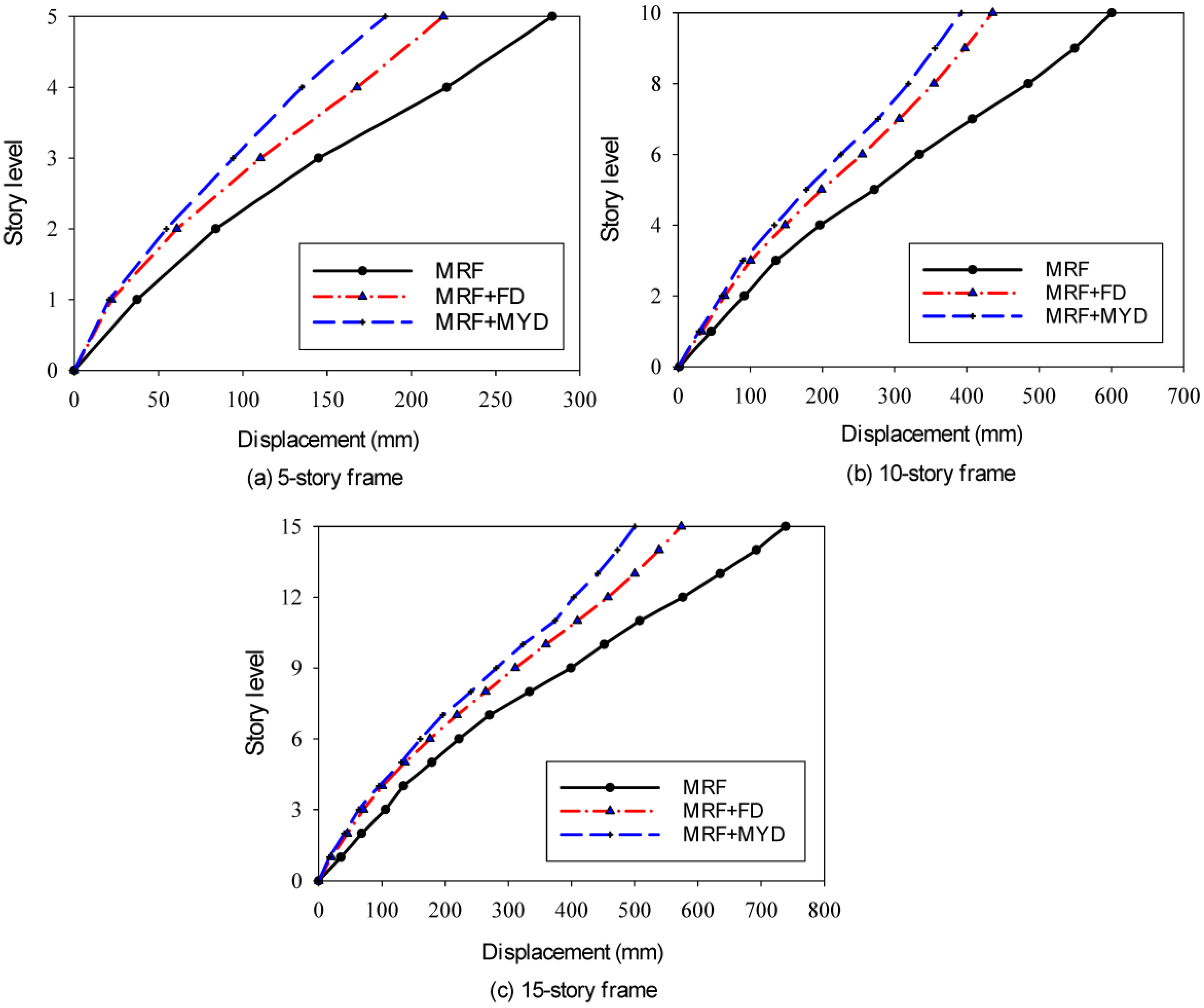
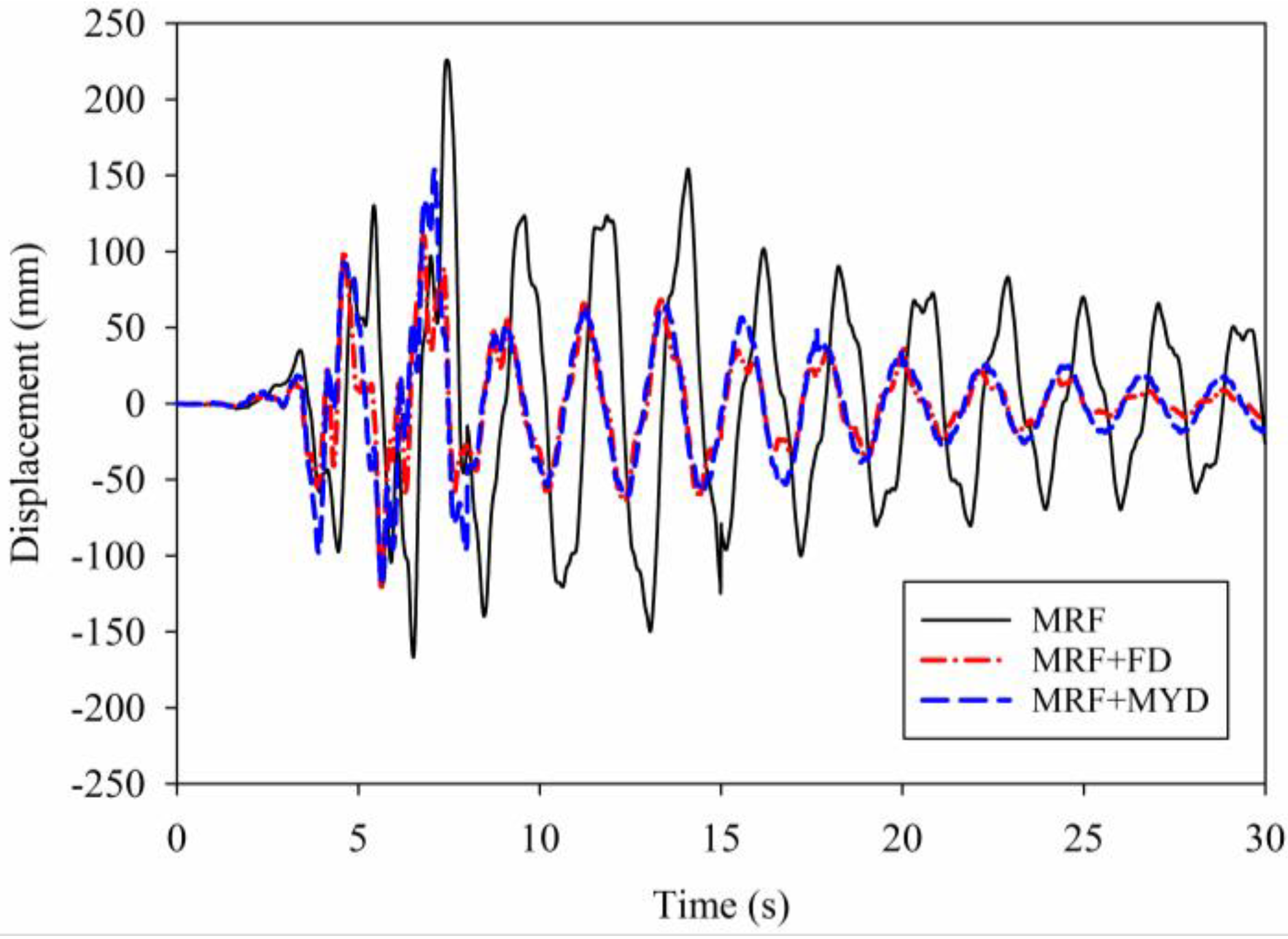
8.1. Lateral Displacement
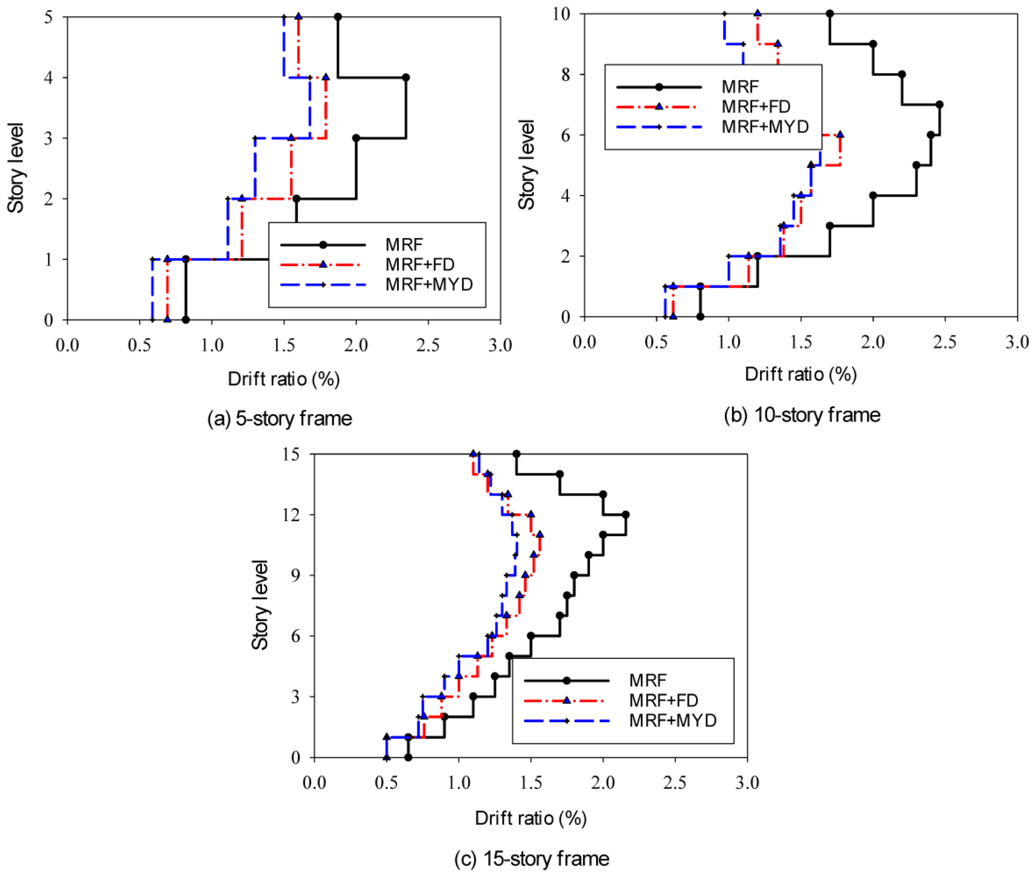
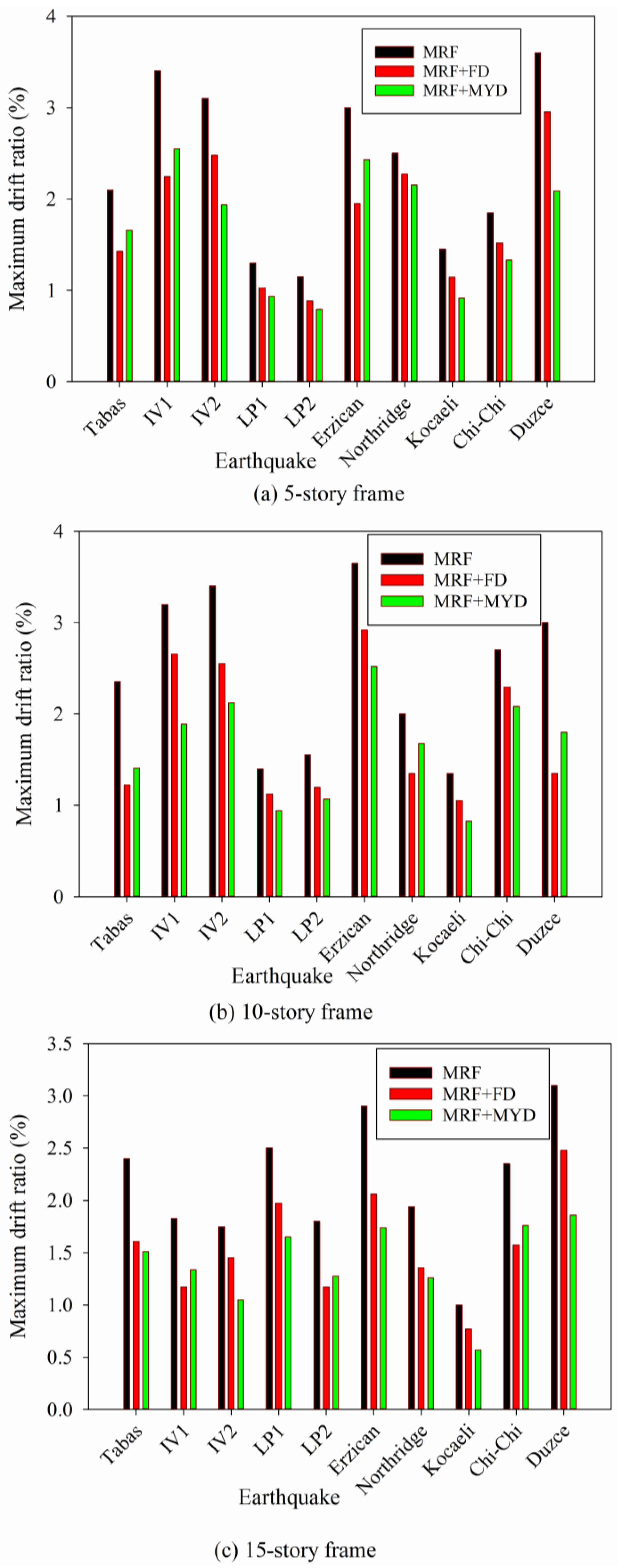
Figure 6 shows the distribution of the average maximum lateral displacements (AMLD) of stories, along with the height of buildings for the bare frames and structures with PFD and MYD based on the non-linear dynamic analyses of the 5-, 10-, and 15-story buildings. The findings show that the strengthening methods enhanced the lateral stiffness of the buildings.
In a 5-story frame structure, the results of the AMLD for the bare frame show that the MLD occurred on the 5th floor, which was 276 mm, and its minimum was on the 1st floor, which was 26.26 mm. As can be shown, the MYD performs better than the PFD at decreasing the AMLD. A reduction of 23% and 35% was achieved in roof displacement for the frame with FDs and MYDs, respectively. The measured time history of the roof displacement of the 5-story frame was under the 1989 Loma Prieta earthquake, which is presented in Figure 7.
As a result, the residual and maximum roof displacements were dramatically reduced as compared to the original frame. In the 10-story structure, the AMLD of the retrofitted frame with both dampers was close to each other. The maximum reduction occurred on the 9th floor, which is a consequence of using the MYD. It should be noted that the addition of the MYD and FD can enhance the initial lateral stiffness of the retrofitted frame, vis-à-vis the bare frame. The increase in the lateral stiffness not only reduces roof displacement but also cuts down the overall displacement of the frame structure. All prototype buildings experienced a decrease in lateral displacement throughout the frame’s height. For instance, Figure 8 illustrates the overall displacement responses of the bare and retrofitted 5-story models under the 1994 Northridge and 1999 Chi-Chi earthquakes.

8.2. Story Drifts

In Figure 9 and Figure 10, the obtained average of the inter-story drift ratios (AIDR) and maximum story drift ratios (MSDR) are shown for 5-, 10-, and 15-story frame structures from the non-linear dynamic analyses done on ten strong ground motions. Following the recommendation of the ASCE 41 [56], three distinct performance levels exist: Immediate Occupancy (IO), Life Safety (LS), and Collapse Prevention (CP). The transient drift ratios for each of these limits are 0.7%, 2.5%, and 5%. The performance limits of IO, LS, and CP are classified as minor, moderate, and severe damage, according to their severity. The MSDR results of the bare frames show that considerable damages occurred along with the height that can result in considerable economic losses and casualties. It is worth mentioning that more floors suffer for significant damage with an increase in the height of the building. The results show that there is no similar trend in drift ratio reduction. In some cases, the FD has better behavior than the MYD, and it is just the opposite in other cases. These results tally with the results of similar studies in the literature [25]. In the 10-story frame structure, it was seen that the highest value of the MSDR occurred under the 1939 Erzincan earthquake. A reduction of 35% and 45% were obtained in drift reduction for the frame with FDs and MYDs, respectively.

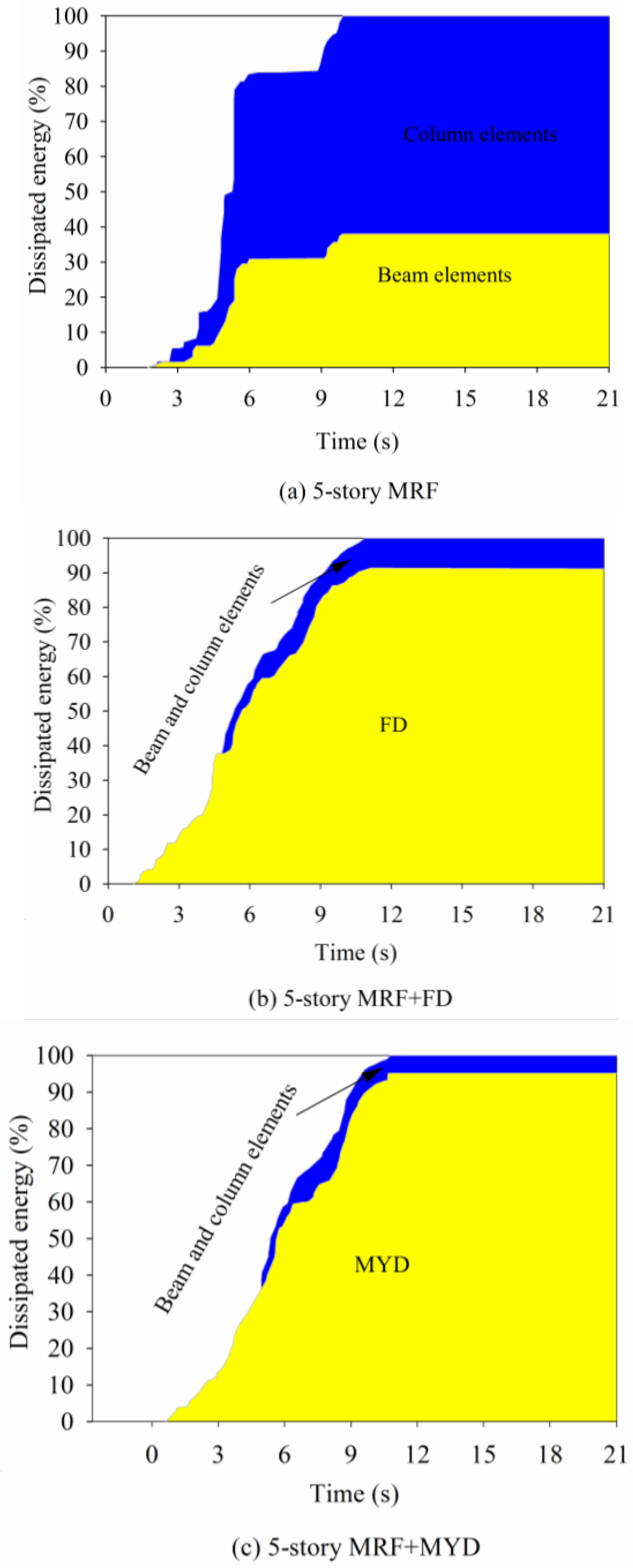
8.3. Energy Absorption

The structural elements and dampers dissipated the input energy when the structures were exposed to the Northridge record, as shown in Figure 11. It should be noted that 62% of the input energy was absorbed by the plastic deformation of the columns in the MRF, and the residual energy was dispersed by the beam elements. The dampers absorbed about 92 percent and 95 percent of the input energy in the 5-story frame reinforced with the 10 FDs and MYDs, respectively, and only a minor amount of energy was dissipated by structural components in the 5-story frame. This means that damage to structural components was greatly reduced after the installation of the dampers and that the forces transmitted from the dampers to the structural members were not enough to cause the members to yield. It is in perfect agreement with the code requirement that the structural members of the frame are equipped with dampers behavior in elastic mode.

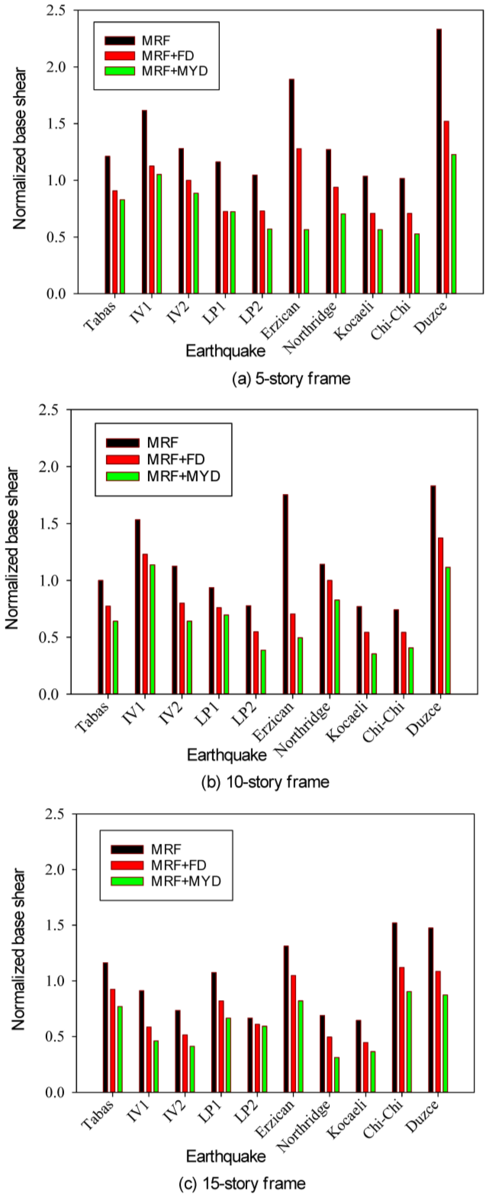
8.4. Shear Distribution
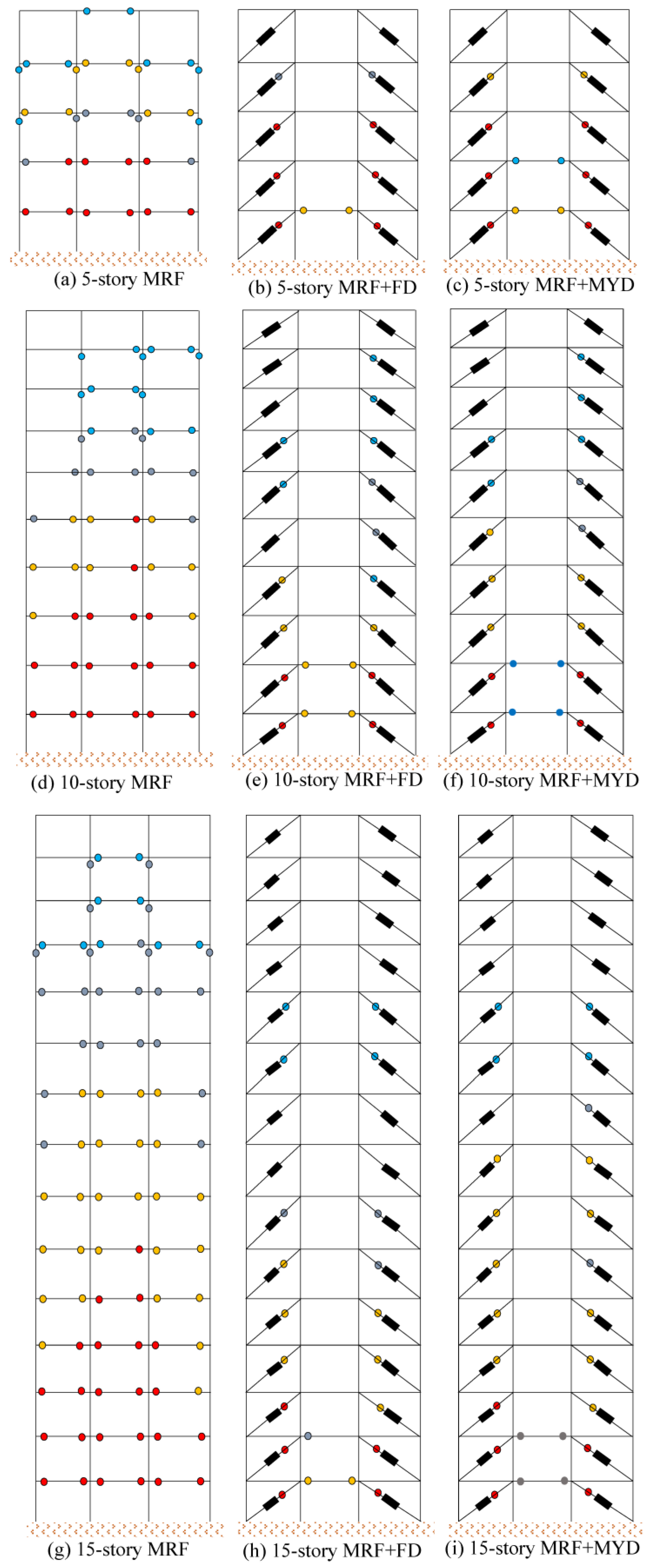
An evaluation of structural shear forces based on numerical FE models was carried out in order to determine the impact of dampers on the seismic efficiency of structures during earthquakes. Shear loads usually derive from relative displacement during an earthquake between the slabs and columns within a structure. To ascertain the highest value of the shear load at each level, the shear loads in each column were accumulated at each story and in each time increment to final yielding of all columns on the intended story. The findings of the dynamic FEM with the influences of the FD and MYD on the 5-, 10- and 15-story buildings show that the base shears were smaller than those of the initial MRF in the strengthened frames.
Figure 12 illustrates the normalized base shear of the prototype structures by the corresponding weight. In general, a steady enhancement was achieved in the maximum total shear load when a PFD replacement by a MYD was applied to the frame. For instance, in the 5-story frame, the peak normalized base shear force under the Kocaeli earthquake was 25% greater for the MRF with the FD than for the MRF equipped with the MYD. Similarly, the base shears under IV1 earthquake excitation were 7% greater for the MRF equipped with the FD than for those with the MYD in the 10-story frame. In frames with both dampers, story shear loads decreased as compared to the frames without dampers. This reduction had been observed in all other models for story shear loads. Both these dampers had sufficient efficiency in decreasing the seismic base shear and story shear loads.
According to Figure 13, the maximum reduction in the median normalized base shear force is related to the frame equipped with the MYD. A small decrease was observed in the basic shear percentage relative to that of the MRF by increasing the structure height from 5 to 15 stories. In other words, the application of the MYD would lead to a minimum value of the base shear force in comparison to the MRF with the FD. Also, the average reductions of 32% and 46% were observed for the frames by using the FD and the MYD in a 5-story frame, respectively.

8.5. Plastic Hinge

In Figure 14, the plastic hinge developments were presented in the three original and retrofitted frames under the Northridge earthquake. Structures in the original frames exhibited non-linear behavior, which was removed or minimized by the use of structural protective systems. When dampers were used, the behavior of the structural element was restricted predominantly to the elastic range, and inelastic deformations were concentrated only in the damping devices. Under earthquakes, collapse did not occur in frames with no dampers. In beams and columns, many plastic hinges were made. There was a non-linear performance in dampers, but the main components did not exhibit significant inelastic behavior. The beams and upper portions of the story columns, particularly the inner columns of the 7th to 9th floors of the 10-story MRF, were found to have plastic hinge formations. The beams and columns of the MRF with dampers showed no non-linear behavior.

9. Discussion

The results obtained from the numerical analysis provide valuable insights into the effectiveness of different strengthening methods for enhancing the seismic response of frame structures. The comparison between the bare frame and retrofitted structures clearly demonstrates the benefits of incorporating PFDs and MYDs. The MYDs, in particular, outperformed the PFDs in reducing the average maximum lateral displacements and roof displacements. This suggests that the MYDs are highly effective in mitigating the structural response to seismic forces, offering improved stiffness and enhanced overall performance compared to the bare frame and structures with PFDs.
The analysis of story drifts revealed that the behavior of the structures varied between the PFDs and MYDs, indicating the complex nature of their influence. While the PFDs showed better behavior in some cases, the MYDs performed more effectively in others. These findings align with previous studies in the literature, which have reported inconsistent trends in drift ratio reduction when different damper types are employed. The choice of damper type should be carefully considered based on the specific characteristics and requirements of the structure, taking into account factors such as building height and expected seismic forces.
Energy absorption is a critical aspect of seismic performance evaluation, and the results of this study highlight the significant role played by PFDs and MYDs in dissipating input energy. The retrofitted frames exhibited reduced damage to structural components, with the dampers absorbing a substantial portion of the input energy. This reduction in damage indicates that the forces transmitted from the dampers to the structural members were effectively controlled, preventing excessive yielding and maintaining the structural elements within the elastic range. The findings align with the design code requirements that aim to ensure structural members equipped with dampers behave predominantly elastically.
The evaluation of shear forces in the retrofitted structures demonstrated the effectiveness of both PFDs and MYDs in reducing base shears and story shear loads. The retrofitted frames consistently exhibited lower shear loads compared to the initial moment-resisting frames (MRFs), indicating the improved seismic efficiency achieved through the incorporation of dampers. The comparison between PFDs and MYDs showed that the MYDs resulted in lower base shear forces, suggesting their higher efficiency in decreasing seismic forces. The reduction in shear loads contributes to improved structural integrity and overall seismic performance of the frame structures.
In conclusion, the findings of this study highlight the positive impact of strengthening methods, specifically PFDs and MYDs, on the seismic response of frame structures. While the MYDs demonstrated superior performance in reducing lateral displacements and roof displacements, the behavior of the dampers in terms of drift ratios exhibited some variability. Nonetheless, both PFDs and MYDs proved effective in energy absorption and reducing shear forces, resulting in improved seismic performance. These results emphasize the importance of carefully selecting and implementing appropriate damper types in structural retrofitting projects to enhance the resilience and seismic resistance of buildings.

10. Optimum Sliding Force

The usefulness of PFDs in lowering the seismic responses of frame structures under various sets of strong ground motions was investigated in previous parts of this work. The findings of the previous investigations revealed that the system behavior is sensitive to sliding friction force [57,58]. So, the sliding force must be tuned. To examine the impact of slip load on PFD performance, a parametric analysis based on performance indicators is performed.

10.1. Performance Indicators

In parametric analysis, four factors such as displacement response, absolute acceleration, base shear, and energy dissipation were addressed. These indicators are dimensionless and calculated as a ratio of the retrofitted frame performance to that of the bare frame. Ideally, these indices should be positive, with values ranging from zero to one. Values close to 0 indicate good performance, while values close to one indicate poor performance. In the following subsections, each index is discussed in greater detail. Each frame is analyzed under three scaled earthquakes (Imperial Valley 1, Chi-Chi, and Northridge), considering a variety of sliding forces. The scaled process is done on the peak ground acceleration of earthquakes. The scaled values are 0.2 g, 0.3 g, and 0.4 g.

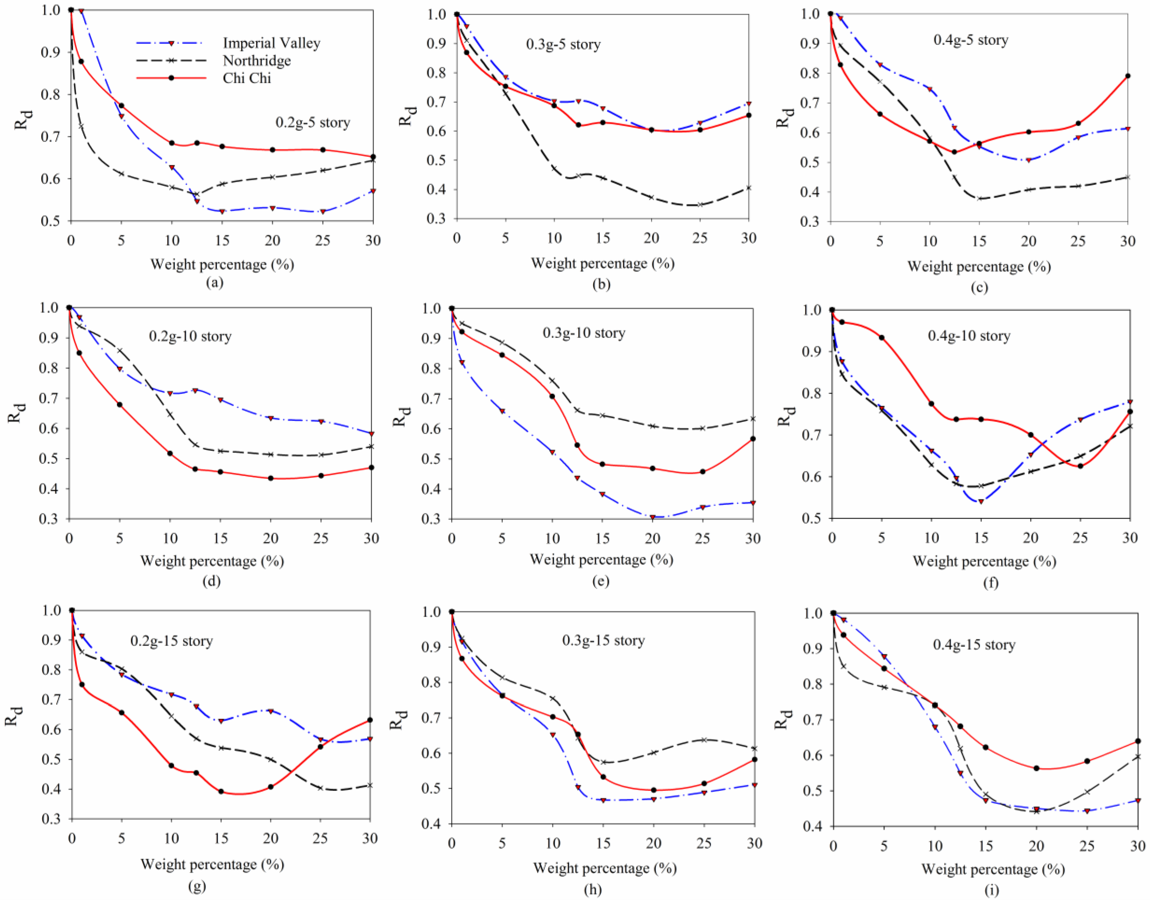
10.2. Displacement Response Index

The displacement index can be expressed as
R d = D r / D 0
where Dr is the maximum roof displacement in the structure equipped with FD and D0 is the maximum roof displacement in the original frame structure. For calculations of the displacement in the structural roof, larger absolute values of displacement in the roof on each side of the vertical axis (positive and negative values) are used. Taking into consideration the diminution of the response, this index is used to assess the total degree of damage.

10.3. Base Shear Index

The base shear index can be defined as
R b s = V r / V 0
where Vr and V0 are the maximum value of base shear of retrofitted and original frames during time history analysis.

10.4. Energy Dissipation Index

Despite not providing quantitative information regarding the damper’s performance, this index provides information on the energy dissipated in friction. This index is determined as
R e = ( E i E f d ) / E i
where Ei and Efd are the total input energy for a structure equipped with FD and hysteretic energy absorbed by the damper at the end of the ground shaking. Although energy dissipation values cannot be calculated for all responses, they provide a failure likelihood in structures during a quake. This index is defined as the remaining energy share in the form of the difference of total energy and dissipated energy by the damper to the total energy ratio for a structure equipped with a FD.

10.5. Efficiency Index

This index is a combination of three previous factors, used by Mualla and Belev [37] for rotating FDs, defined as follows:
S P I = R d 2 + R f 2 + R e 2
where Rf, Rd, and Re are the response reduction factors in accordance with maximum total base shear, maximum response displacement, and total seismic input energy, respectively.
Furthermore, if the three performance indicators are of varying relevance, the relevant weight factors wd, wf, and we may be incorporated in Equation (6), resulting in
S P I = w d 2 R d 2 + w f 2 R f 2 + w e 2 R e 2
where wd, wf, and we are the response reduction factor weight coefficient, the base shear reduction factor weight coefficient, and the damper energy dissipation factor weight, respectively.

11. Parametric Analysis Results and Discussion

11.1. Displacement Index

Dynamic analysis results of 5-, 10-, and 15-story frame structures are expressed as a ratio of the structure displacement to the original structure displacement, as depicted in Figure 15, as a function of the sliding force ratio. The obtained displacement index (Rd) of the frame structures does not show a unique trend. In some cases, a reduction in the displacement index occurred as the weight percentage increased up to 20%.
The survey results of the 5-story frame show that the maximum roof displacement reduction occurred in 25% of the frame weight and PGAs of 0.3 g and 0.4 g. In the Northridge earthquake, upon quake severity increase, this reduction intensified, while in other earthquakes, this reduction was under two PGAs of 0.2 g and 0.3 g. In other earthquakes with PGAs of 0.2 g, the optimized sliding value was achieved within a range of 10~15% of the frame weight, and in other PGAs, within a higher range of 20~25% of the frame weight. In the 10- and 15-story frames, the proper sliding values were mainly achieved within 20~30% and 15~20% of the frame weight, respectively. In these frames, the appropriate percentage of the displacement reduction factor in most PGA values was achieved less often than that of the 5-story frame. In the 10-story building, the optimized sliding values were 15% and 12.5% of the total weight for Imperial Valley and Northridge earthquakes with PGA of 0.4 g, respectively. The minimum factor value of the displacement index was achieved in the earthquakes with PGA of 0.3 g.

11.2. Base Shear Index

Figure 16 depicts the acquired findings of the base shear index (Rbs) of 5-, 10-, and 15-story frames. The results show that the shear index decreased when the weight percentage increased to about 15%; thus, it was adversely influenced by an increase in weight percentage. Therefore, the optimal shear index can be achieved in the range of 10% to 15% of the seismic weight of the structure. In addition, the decrease rate of the shear index is higher with increasing intensity in the low- and mid-rise structures.
For example, the best sliding force values were achieved within 5% to 10% of the total seismic weight for the 5-story frame. In the 10-story frame, the percentage of such sliding increased within the 10–15% range for the 5-story frame and the 15-story frame. The optimized sliding value was achieved within the 10–15% range under all base accelerations. As a result, the damper provides a more appropriate value for the sliding force if the frame height is increased. In other words, increasing the frame height decreases the damper sensitivity regarding a certain value of the sliding force, which is quite apparent regarding the 15-story frame.

11.3. Energy Index

Figure 17 depicts the variations in the energy index (Re) as a function of the FD’s sliding force as specified by weight percentage. As shown in Figure 17, two distinct trends emerged. The ratio of the energy index decreased steadily between 10 and 15% of the weight percentage, from about 1 to 0.35. This was the lowest figure in the period. Afterward, the energy index rose slowly to 30%. For instance, the energy index for the five-story under the Northridge earthquake gradually fell from 1 to a minimum of 0.38 in 15% of the seismic weight. Also, in 10- and 15-story frames, the proper value of the durable energy factor occurred in 0.3 g and 0.4 g base accelerations. On the other hand, the most suitable sliding force value increased with a rise in the height and intensity major of the earthquake.

11.4. Efficiency Index

Figure 18 depicts the friction-damped frame’s efficiency index (EF). The optimum percentage of the seismic weight ranged from 10% to 15%. For a weight percentage larger than 15%, despite some fluctuations, the EF continued to rise until it hit 30%. For a weight percentage of more than 10%, optimal EF can be reached, however this is accompanied by a rise in the base shear. The results of the five-story frame show that the damper delivered an efficient performance under the Northridge earthquake for all the intensity measures, in comparison with other earthquakes. In the 10-story frame, the minimum EF (94%) was achieved for the Northridge earthquake with PGA = 0.4 g and a 15% sliding force. Similarly, it was 85% for the Chi-Chi earthquake in the 15-story frame.

12. Concluding Remarks

The research investigated the effectiveness of two seismic protection systems, namely PFDs and MYDs, in improving the seismic response of three prototype structures considering SSI effects. The main findings of the study are summarized as follows:
  • The inclusion of dampers, resulted in a significant reduction in residual and maximum roof displacement. Moreover, the maximum story drift ratio indicated that significant damage occurred at higher levels, which could lead to substantial economic losses and potential casualties.
  • In the original frames, a major portion of the seismic energy input was absorbed by the nonlinear deformation of beams and columns, while in the retrofitted frames, the dampers dissipated up to 90% of the input energy. The structural elements in the reinforced frames dissipated a comparatively smaller amount of energy.
  • The maximum base shear experienced a decrease in all models and under all considered earthquakes with the addition of both types of dampers. The reduction in base shear loads ranged from 11% to 65% when utilizing MYDs, and a decrease of 10% to 60% was observed with the implementation of PFDs.
  • The structures without any dampers were capable of withstanding the seismic records through the development of plastic hinges in the structural elements. However, the introduction of dampers transferred the inelastic behavior to these devices rather than the critical structural components.
  • The optimal energy, shear, and efficiency indexes were achieved within the range of 10% to 15% of the seismic weight of the structure.
  • One limitation of the work is that the analysis focused on a specific set of prototype structures, and the findings may not be directly applicable to other types of buildings. Additionally, the study primarily considered the structural response under seismic loading without considering other potential hazards or multi-hazard scenarios that could affect the performance of the seismic protection systems. Further research is needed to explore the generalizability of the findings and to investigate the behavior of the systems under different loading conditions and in combination with other hazards.
  • Recommendations for future work include conducting experimental studies to validate the proposed seismic protection systems, performing a three-dimensional parametric study to optimize damper design parameters, and incorporating dynamic soil-structure interaction (DSSI) effects for a more realistic assessment of structural response.

Author Contributions

Conceptualization, M.A. and M.E.-J.; methodology, M.A. and M.E.-J.; software, M.A. and M.E.-J.; validation, M.A. and M.E.-J.; formal analysis, M.A. and M.E.-J.; investigation, M.A. and M.E.-J.; resources, M.E.-J.; data curation, M.E.-J.; writing—original draft preparation, M.E.-J.; writing—review and editing, M.A.; visualization, M.E.-J.; supervision, M.A. All authors have read and agreed to the published version of the manuscript.

Funding

This research received no external funding.

Institutional Review Board Statement

Not applicable.

Informed Consent Statement

Not applicable.

Data Availability Statement

The data presented in this study are available on request from the corresponding author. The data are not publicly available due to privacy.

Conflicts of Interest

The authors declare no conflict of interest.

References

  1. Gkournelos, P.D.; Triantafillou, T.C.; Bournas, D.A. Seismic Upgrading of Existing Reinforced Concrete Buildings: A State-of-the-Art Review. Eng. Struct. 2021, 240, 112273. [Google Scholar] [CrossRef]
  2. Bird, J.F.; Bommer, J.J. Earthquake Losses Due to Ground Failure. Eng. Geol. 2004, 75, 147–179. [Google Scholar] [CrossRef]
  3. Ahmadi, M.; Ebadi Jamkhaneh, M. Numerical Investigation of Energy Dissipation Device to Improve Seismic Response of Existing Steel Buildings with Soft-First-Story. Int. J. Steel Struct. 2021, 21, 691–702. [Google Scholar] [CrossRef]
  4. Aydin, E.; Ozturk, B.; Bogdanovic, A.; Farsangi, E.N. Influence of Soil-Structure Interaction (SSI) on Optimal Design of Passive Damping Devices. In Structures; Elsevier: Amsterdam, The Netherlands, 2020; Volume 28, pp. 847–862. [Google Scholar]
  5. Wang, L.; Shi, W.; Zhou, Y. Adaptive-Passive Tuned Mass Damper for Structural Aseismic Protection Including Soil–Structure Interaction. Soil. Dyn. Earthq. Eng. 2022, 158, 107298. [Google Scholar] [CrossRef]
  6. Maleska, T.; Beben, D. Behaviour of Soil–Steel Composite Bridges under Strong Seismic Excitation with Various Boundary Conditions. Materials 2023, 16, 650. [Google Scholar] [CrossRef]
  7. Jalali, H.H.; Farzam, M.F.; Gavgani, S.A.M.; Bekdaş, G. Semi-Active Control of Buildings Using Different Control Algorithms Considering SSI. J. Build. Eng. 2023, 67, 105956. [Google Scholar] [CrossRef]
  8. Ebadi-Jamkhaneh, M.; Rezaei, M.; Ahmadi, M. Seismic Behavior of Steel Braced Frames Equipped with Metal Foam. Int. J. Steel Struct. 2021, 21, 1420–1430. [Google Scholar] [CrossRef]
  9. Zhang, W.; Liu, S.; Shokrabadi, M.; Dehghanpoor, A.; Taciroglu, E. Nonlinear Seismic Fragility Assessment of Tall Buildings Equipped with Tuned Mass Damper (TMD) and Considering Soil-Structure Interaction Effects. Bull. Earthq. Eng. 2022, 20, 3469–3483. [Google Scholar] [CrossRef]
  10. Yanik, A.; Ulus, Y. Soil–Structure Interaction Consideration for Base Isolated Structures under Earthquake Excitation. Buildings 2023, 13, 915. [Google Scholar] [CrossRef]
  11. Forcellini, D. Seismic Fragility of Tall Buildings Considering Soil Structure Interaction (SSI) Effects. In Proceedings of the Structures; Elsevier: Amsterdam, The Netherlands, 2022; Volume 45, pp. 999–1011. [Google Scholar]
  12. Cao, X.-Y.; Feng, D.-C.; Beer, M. Consistent Seismic Hazard and Fragility Analysis Considering Combined Capacity-Demand Uncertainties via Probability Density Evolution Method. Struct. Saf. 2023, 103, 102330. [Google Scholar] [CrossRef]
  13. Housner, G.W.; Bergman, L.A.; Caughey, T.K.; Chassiakos, A.G.; Claus, R.O.; Masri, S.F.; Skelton, R.E.; Soong, T.T.; Spencer, B.F.; Yao, J.T.P. Structural Control: Past, Present, and Future. J. Eng. Mech. 1997, 123, 897–971. [Google Scholar] [CrossRef]
  14. Whittaker, A.S.; Bertero, V.V.; Thompson, C.L.; Alonso, L.J. Seismic Testing of Steel Plate Energy Dissipation Devices. Earthq. Spectra 1991, 7, 563–604. [Google Scholar] [CrossRef]
  15. Martínez, C.A.; Curadelli, O.; Compagnoni, M.E. Optimal Placement of Nonlinear Hysteretic Dampers on Planar Structures under Seismic Excitation. Eng. Struct. 2014, 65, 89–98. [Google Scholar] [CrossRef]
  16. Erochko, J.; Christopoulos, C.; Tremblay, R.; Choi, H. Residual Drift Response of SMRFs and BRB Frames in Steel Buildings Designed According to ASCE 7-05. J. Struct. Eng. 2011, 137, 589–599. [Google Scholar] [CrossRef]
  17. Wang, W.; Yang, Z.; Hua, X.; Chen, Z.; Wang, X.; Song, G. Evaluation of a Pendulum Pounding Tuned Mass Damper for Seismic Control of Structures. Eng. Struct. 2021, 228, 111554. [Google Scholar] [CrossRef]
  18. Kamgar, R.; Gholami, F.; Zarif Sanayei, H.R.; Heidarzadeh, H. Modified Tuned Liquid Dampers for Seismic Protection of Buildings Considering Soil–Structure Interaction Effects. Iran. J. Sci. Technol. Trans. Civil. Eng. 2020, 44, 339–354. [Google Scholar] [CrossRef]
  19. Yanik, A. Seismic Control Performance Indices for Magneto-Rheological Dampers Considering Simple Soil-Structure Interaction. Soil. Dyn. Earthq. Eng. 2020, 129, 105964. [Google Scholar] [CrossRef]
  20. Sarcheshmehpour, M.; Estekanchi, H.E.; Ghannad, M.A. Optimum Placement of Supplementary Viscous Dampers for Seismic Rehabilitation of Steel Frames Considering Soil–Structure Interaction. Struct. Des. Tall Spec. Build. 2020, 29, e1682. [Google Scholar] [CrossRef]
  21. Guo, L.; Wang, J.; Wang, W.; Wang, H. Experimental, Numerical and Analytical Study on Seismic Performance of Shear-Bending Yielding Coupling Dampers. Eng. Struct. 2021, 244, 112724. [Google Scholar] [CrossRef]
  22. Mirzabagheri, S.; Sanati, M.; Aghakouchak, A.A.; Khadem, S.E. Experimental and Numerical Investigation of Rotational Friction Dampers with Multi Units in Steel Frames Subjected to Lateral Excitation. Arch. Civ. Mech. Eng. 2015, 15, 479–491. [Google Scholar] [CrossRef]
  23. Fazli Shahgoli, A.; Zandi, Y.; Rava, A.; Baharom, S.; Paknahad, M.; Ahmadi, M.; Wakil, K. Estimation of the Most Influential Parameters Affecting the Rotary Braces Damper. Iran. J. Sci. Technol. Trans. Civil. Eng. 2021, 45, 2463–2475. [Google Scholar] [CrossRef]
  24. Vaiana, N.; Rosati, L. Classification and Unified Phenomenological Modeling of Complex Uniaxial Rate-Independent Hysteretic Responses. Mech. Syst. Signal Process 2023, 182, 109539. [Google Scholar] [CrossRef]
  25. Bagheri, S.; Barghian, M.; Saieri, F.; Farzinfar, A. U-Shaped Metallic-Yielding Damper in Building Structures: Seismic Behavior and Comparison with a Friction Damper. In Structures; Elsevier: Amsterdam, The Netherlands, 2015; Volume 3, pp. 163–171. [Google Scholar]
  26. Martinez-Romero, E. Experiences on the Use of Supplementary Energy Dissipators on Building Structures. Earthq. Spectra 1993, 9, 581–625. [Google Scholar] [CrossRef]
  27. Wada, A.; Huang, Y.; Iwata, M. Passive Damping Technology for Buildings in Japan. Progress. Struct. Eng. Mater. 2000, 2, 335–350. [Google Scholar] [CrossRef]
  28. Jarrah, M.; Khezrzadeh, H.; Mofid, M.; Jafari, K. Experimental and Numerical Evaluation of Piston Metallic Damper (PMD). J. Constr. Steel Res. 2019, 154, 99–109. [Google Scholar] [CrossRef]
  29. Kelly, J.M.; Skinner, R.I.; Heine, A.J. Mechanisms of Energy Absorption in Special Devices for Use in Earthquake Resistant Structures. Bull. NZ Soc. Earthq. Eng. 1972, 5, 63–88. [Google Scholar] [CrossRef]
  30. Skinner, R.I.; Kelly, J.M.; Heine, A.J. Hysteretic Dampers for Earthquake-resistant Structures. Earthq. Eng. Struct. Dyn. 1974, 3, 287–296. [Google Scholar] [CrossRef]
  31. Dolce, M.; Filardi, B.; Marnetto, R.; Nigro, D. Experimental Tests and Applications of a New Biaxial Elasto-Plastic Device for the Passive Control of Structures. Spec. Publ. 1996, 164, 651–674. [Google Scholar]
  32. Deng, K.; Pan, P.; Wang, C. Development of Crawler Steel Damper for Bridges. J. Constr. Steel Res. 2013, 85, 140–150. [Google Scholar] [CrossRef]
  33. Jamkhaneh, M.E.; Ebrahimi, A.H.; Amiri, M.S. Experimental and Numerical Investigation of Steel Moment Resisting Frame with U-Shaped Metallic Yielding Damper. Int. J. Steel Struct. 2019, 19, 806–818. [Google Scholar] [CrossRef]
  34. Pall, A.S.; Marsh, C. Response of Friction Damped Braced Frames. J. Struct. Eng. 1982, 108, 1313–1323. [Google Scholar] [CrossRef]
  35. Fitzgerald, T.F.; Anagnos, T.; Goodson, M.; Zsutty, T. Slotted Bolted Connections in Aseismic Design for Concentrically Braced Connections. Earthq. Spectra 1989, 5, 383–391. [Google Scholar] [CrossRef]
  36. Zhou, X.; Peng, L. A New Type of Damper with Friction-Variable Characteristics. Earthq. Eng. Eng. Vib. 2009, 8, 507–520. [Google Scholar] [CrossRef]
  37. Mualla, I.H.; Belev, B. Performance of Steel Frames with a New Friction Damper Device under Earthquake Excitation. Eng. Struct. 2002, 24, 365–371. [Google Scholar] [CrossRef]
  38. Liao, W.; Mualla, I.; Loh, C.-H. Shaking-table Test of a Friction-damped Frame Structure. Struct. Des. Tall Spec. Build. 2004, 13, 45–54. [Google Scholar] [CrossRef]
  39. Vaiana, N.; Capuano, R.; Rosati, L. Evaluation of Path-Dependent Work and Internal Energy Change for Hysteretic Mechanical Systems. Mech. Syst. Signal Process 2023, 186, 109862. [Google Scholar] [CrossRef]
  40. Computers and Structures, Integrated Structural Analysis and Design Software, SAP2000. 2010. Available online: https://www.csiamerica.com/products/sap2000 (accessed on 1 June 2023).
  41. McKenna, F.; Fenves, G.L.; Scott, M.H. Open System for Earthquake Engineering Simulation; Pacific Earthquake Engineering Research Center, University of California: Berkeley, CA, USA, 2000. [Google Scholar]
  42. American Institute of Steel Construction. Specification for Structural Steel Buildings (ANSI/AISC 360); American Institute of Steel Construction: Chicago, IL, USA, 2010. [Google Scholar]
  43. Ahmadi, M.; Naderpour, H.; Kheyroddin, A.; Gandomi, A.H. Seismic Failure Probability and Vulnerability Assessment of Steel-Concrete Composite Structures. Periodica Polytech. Civil Eng. 2017, 61, 939–950. [Google Scholar] [CrossRef] [Green Version]
  44. Scott, M.H. Numerical Integration Options for the Force-Based Beam-Column Element in OpenSees. Force-Based Elem. Integr. Options OpenSees 2011, 1–7. [Google Scholar]
  45. Scott, M.H.; Fenves, G.L. Plastic Hinge Integration Methods for Force-Based Beam–Column Elements. J. Struct. Eng. 2006, 132, 244–252. [Google Scholar] [CrossRef]
  46. Curras, C.J.; Boulanger, R.W.; Kutter, B.L.; Wilson, D.W. Dynamic Experiments and Analyses of a Pile-Group-Supported Structure. J. Geotech. Geoenviron. Eng. 2001, 127, 585–596. [Google Scholar] [CrossRef]
  47. Boulanger, R.W.; Curras, C.J.; Kutter, B.L.; Wilson, D.W.; Abghari, A. Seismic Soil-Pile-Structure Interaction Experiments and Analyses. J. Geotech. Geoenviron. Eng. 1999, 125, 750–759. [Google Scholar] [CrossRef]
  48. Chanda, D.; Nath, U.; Saha, R.; Haldar, S. Development of Lateral Capacity-Based Envelopes of Piled Raft Foundation under Combined VMH Loading. Int. J. Geomech. 2021, 21, 4021075. [Google Scholar] [CrossRef]
  49. Chanda, D.; Saha, R.; Haldar, S. Behaviour of Piled Raft Foundation in Sand Subjected to Combined VMH Loading. Ocean. Eng. 2020, 216, 107596. [Google Scholar] [CrossRef]
  50. Dutta, S.C.; Bhattacharya, K.; Roy, R. Effect of Flexibility of Foundations on Its Seismic Stress Distribution. J. Earthq. Eng. 2008, 13, 22–49. [Google Scholar] [CrossRef]
  51. Saha, R.; Dutta, S.C.; Haldar, S. Effect of Raft and Pile Stiffness on Seismic Response of Soil-Piled Raft-Structure System. Struct. Eng. Mech. 2015, 55, 161–189. [Google Scholar] [CrossRef]
  52. American Society of Civil Engineers. Minimum Design Loads for Buildings and Other Structures: Second. Printing (ASCE/SEI 7); American Society of Civil Engineers: Reston, VA, USA, 2010. [Google Scholar]
  53. Cao, X.-Y.; Feng, D.-C.; Li, Y. Assessment of Various Seismic Fragility Analysis Approaches for Structures Excited by Non-Stationary Stochastic Ground Motions. Mech. Syst. Signal Process 2023, 186, 109838. [Google Scholar] [CrossRef]
  54. Shen, H.; Zhang, R.; Weng, D.; Gao, C.; Luo, H.; Pan, C. Simple Design Method of Structure with Metallic Yielding Dampers Based on Elastic–Plastic Response Reduction Curve. Eng. Struct. 2017, 150, 98–114. [Google Scholar] [CrossRef]
  55. López-Almansa, F.; De La Cruz, S.T.; Taylor, C. Experimental Study of Friction Dissipators for Seismic Protection of Building Structures. Earthq. Eng. Eng. Vib. 2011, 10, 475–486. [Google Scholar] [CrossRef] [Green Version]
  56. American Society of Civil Engineers. Seismic Rehabilitation of Existing Buildings (ASCE/SEI 41); American Society of Civil Engineers: Reston, VA, USA, 2006. [Google Scholar]
  57. Ciğeroğlu, E.; Özgüven, H.N. Nonlinear Vibration Analysis of Bladed Disks with Dry Friction Dampers. J. Sound. Vib. 2006, 295, 1028–1043. [Google Scholar] [CrossRef]
  58. Bhaskararao, A.V.; Jangid, R.S. Seismic Analysis of Structures Connected with Friction Dampers. Eng. Struct. 2006, 28, 690–703. [Google Scholar] [CrossRef]
Figure 1. Plan and elevation views of buildings.
Buildings 13 01587 g001
Figure 2. Ground motion time histories and spectral accelerations of 10 records. (a) Tabas, LP1, and LP2. (b) IV1, IV2, and Kocaeli. (c) Chi-Chi and Duzce. (d) Erzican and Northridge. (e) spectral accelerations.
Buildings 13 01587 g002aBuildings 13 01587 g002b
Figure 3. Two-story reduced-scale steel frame.
Buildings 13 01587 g003
Figure 4. Comparison of second-story displacement of test and simulated results.
Buildings 13 01587 g004
Figure 5. Comparison between the experimental sample and numerical model in terms of drift ratio.
Buildings 13 01587 g005
Figure 6. Average lateral displacement of three frames during earthquakes.
Buildings 13 01587 g006
Figure 7. Time history displacement of roof level of the 5-story frame during the Loma Prieta earthquake.
Buildings 13 01587 g007
Figure 8. Lateral displacement of the 5-story frame during the Northridge and Chi-Chi earthquakes.
Buildings 13 01587 g008
Figure 9. Average inter-story drift ratio of 5-, 10-, and 15-story frames.
Buildings 13 01587 g009
Figure 10. Maximum inter-story drift ratio of 5-, 10-, and 15- story frames compared to different records.
Buildings 13 01587 g010
Figure 11. Dissipated energy in 5-story frames during the Northridge earthquake.
Buildings 13 01587 g011
Figure 12. Normalized base shear of 5-, 10-, and 15-story frames.
Buildings 13 01587 g012
Figure 13. Normalized base shear of 5-, 10-, and 15-story frames during different earthquakes.
Buildings 13 01587 g013
Figure 14. Plastic hinge formation on different systems during Northridge earthquakes (Red: collapse. Yellow: near collapse. Blue: life safe. Gray: operational).
Buildings 13 01587 g014
Figure 15. Displacement reduction index for 5-, 10-, and 15-story frames under three records.
Buildings 13 01587 g015
Figure 16. Shear base reduction index for 5-, 10-, and 15-story frames under three records.
Buildings 13 01587 g016
Figure 17. Dissipated energy index for 5-, 10-, and 15-story frames under three records.
Buildings 13 01587 g017
Figure 18. SPI for 5-, 10-, and 15-story frames under three records.
Buildings 13 01587 g018
Table 1. Geometrical features of structural elements in three types of buildings.
Prototype StructuresStory LevelColumnBeam
5-story1–2C300-8IPE180
3–4C300-8IPE160
5C300-6IPE140
10-story1–2C400-102IPE180
3–4C350-102IPE180
5–6C350-8IPE200
7–8C300-6IPE180
9–10C300-6IPE160
15-story1–3C450-102IPE220
4–6C450-82IPE200
7–9C400-82IPE200
10–12C350-62IPE180
13–15C300-62IPE140
Table 2. Synopsis of the seismic records.
NameEventStationDateMagnitudePGA
(g)
Tp
(s)
AI
(m/s)
SIR (m/s/s)
TabasTabasDayhook19787.350.4090.381.40.144
IV1Imperial Valley-06ElCentroArray #719796.530.3410.701.70.238
IV2Imperial Valley-06El Centro Differential Array19796.530.3530.162.10.34
LP1Loma PrietaFoster City–APEEL119896.930.2910.501.80.093
LP2Loma PrietaHollister Diff. Array19896.930.2640.721.00.136
ErzicanErzican, TurkeyErzincan19926.690.4790.301.80.559
NorthridgeNorthridge-01Northridge -17645 Saticoy 19946.690.4750.424.60.218
KocaeliKocaeli, TurkeyDuzce19997.510.3260.381.30.125
Chi-ChiChi-Chi, TaiwanCHY03619997.620.2730.541.90.108
DuzceDuzce, TurkeyDuzce19997.140.4270.402.90.652
Note: S I R = I a 5 75 / D 5 75 , T p : predominant period, AI: arias intensity.
Table 3. Sliding force for different weight percentage of various stories.
StoryWeight Percentage (%)
151012.515202530
5-story75037507500937511,25015,00018,75022,500
10-story8054025805010,062.512,07516,10020,12524,150
15-story832.34161.78323.310,404.212,48516,646.720,808.324,970
Table 4. Geometrical characteristics of the structural elements.
MemberSection (mm)Shape
Column40 × 40 × 3Square hollow
Beam40 × 40 × 3Square hollow
Brace (xz)26.9 × 3.2Circular hollow
Brace (yz)25 × 3Strip
Table 5. Column, beam, and damper dimensions (dimensions in mm).
Story LevelColumnBeam
( b f h w t f t w )
Damper
1C400-8110-220-10-8UD5
2C400-8110-220-10-8UD4
3C350-8100-200-10-8UD3
4C350-8100-200-10-8UD7
Table 6. Maximum drift ratio of the test specimen and numerical model.
Story Level1st2nd3rd4th
Experimental model0.5300.5750.7760.752
FEM model0.5000.5840.7600.740
Variation (%)−5.6+1.5−2.0−1.6
Disclaimer/Publisher’s Note: The statements, opinions and data contained in all publications are solely those of the individual author(s) and contributor(s) and not of MDPI and/or the editor(s). MDPI and/or the editor(s) disclaim responsibility for any injury to people or property resulting from any ideas, methods, instructions or products referred to in the content.

