1. Introduction
Integrated modular house by flat pack is a light steel structure with modular design, factory fabrication, packaged transportation, and on-site modular assembly, as shown in
Figure 1. Its characteristics include rapid disassembly, modular combination, re-usability, efficient transportation, and green and environmentally friendly [
1,
2,
3]. Therefore, they are extensively utilized in scenarios such as emergency rescue, military deployment, and construction operations [
4,
5,
6,
7].
However, the absence of established standards and norms in the realm of prefabricated buildings highlights the necessity of delving into their mechanical properties. This exploration is crucial for advancing the field of prefabrication in architecture [
8]. Over the past few years, a significant number of researchers have devoted efforts to studying this area, using a diverse range of research methods.
Among them, the experimental approach is extensively employed due to its appropriateness for practical engineering scenarios and its ability to yield clear results. For instance, Dai Mingming conducted field experiments to examine the dynamic properties of prefabricated cold-formed thin-walled light steel movable plate houses [
9]. Yoshihide Tominaga assessed the impact of wind load on double-sloping roofs using wind tunnel experiments [
10]. Similarly, Liu Y investigated the earthquake resistance of corner-supported modular steel structures by performing full-scale frame-loading tests [
11]. Ma SC, via elastic loading tests, destructive tests, and low-cyclic repeated loading tests, studied the seismic performance of prefabricated integrated floor truss beams, alkali-resistant glass fiber ceramsite concrete sandwich composite shear walls, and structurally integrated insulated composite wall panel joints [
12,
13,
14].
However, experimental investigations often face several constraints, such as limited location conditions and challenges in forecasting structural deformation trends. These challenges can be effectively overcome via numerical analysis and finite element simulations. For example, Li Sheng investigated the dynamic properties of a light steel movable plate house using the free vibration attenuation method combined with finite element simulation [
15]. Lin Hsin-Hung examined the effect of ventilation airflow on a container room using simulation analysis and numerical calculations [
16]. Fan Kunjie conducted an analysis of the lateral stiffness of the side plate of a container house employing skin theory [
17].
The bolted connection is typically used between the corner fitting of the structure, which is often considered a semi-rigid connection. For semi-rigid connections, the research methods are divided into the following four kinds. Firstly, a spring element without length is utilized to simulate the flexibility of connection and analyze the nodes in an elastic manner [
18,
19]. Secondly, finite element models of semi-rigid connections are established to calculate the stress conditions [
20,
21,
22,
23,
24]. The third one is to modify the traditional theoretical method for a specific structure with a semi-rigid connection [
25,
26,
27,
28]. The fourth one is to analyze the load–displacement relationship of a semi-rigid connection based on test data [
29,
30,
31,
32,
33,
34,
35]. Although the connections of the integrated modular house by flat pack are generally analyzed using the semi-rigid connection method in previous studies, the force transfer mechanism and the mechanical properties of connections considering the contact mechanics have not been reported.
Therefore, to effectively address joint contact and overcome the limitation of oversimplifying this kind of joint in current finite element simulations, refined finite element models of the integrated modular house by flat pack structures are established, and the connections are simulated based on elastic–plastic contact theory to analyze the stress and displacement of the house under different loading conditions. Additionally, experimental tests on the corner column of the house are carried out. The weld strength of the corner fitting joint is validated, and the repeated disassembly performance of the corner fitting joint is investigated. Based on the above research, the safety and reliability of the assembled house structure are comprehensively verified, providing a practical basis for the optimization of the house structure.
2. Elastic–Plastic Contact Theory and Penalty Function Method
Both elastic–plastic and contact theories involve boundary undetermined problems. When subjected to a load, both elastic and plastic zones may be produced inside a structure [
36]. For the semi-rigid connections of the integrated modular house by flat pack, the force transfer process is relatively complicated. The actual contact condition between corner fittings and corner columns can hardly be defined quantitatively and precisely. To better reflect the real internal force and deformation of the structure, the finite element analysis of integrated modular house by flat pack is carried out based on the elastic–plastic contact theory.
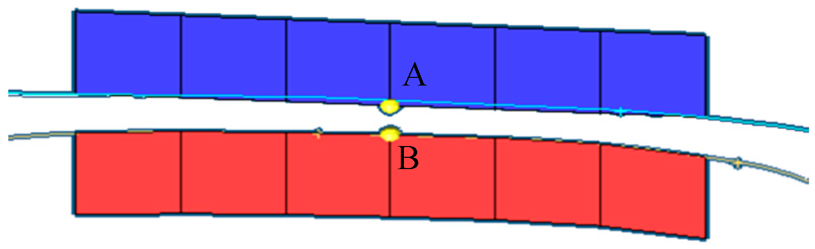
Elastic–plastic contact requires discretization of the contact interface. It is assumed that a pair of contact blocks, including active contact blocks and passive contact blocks, is called a contact pair, and the corresponding nodes are defined as A and B, respectively shown in
Figure 2, and M and N in finite element coordinates, respectively. The contact surface is assumed to be a two-dimensional plane, and the active contact block is a 4-node element. The point T on the active contact block (independent of the element) and the point L on the passive contact block are selected, and the relative displacement
u between them is calculated according to Formula (1).
The matrix form of is .
is the unit interpolation function, and the matrix form is
, where I is a 3 × 3 unit matrix. The coordinates in the local coordinate system can be obtained by transforming the coordinates of Formula (1), as shown in Formula (2).
θ is the transformation of the matrix for the coordinate system. It is expressed by the projection components of the vector
in the Cartesian coordinate system along the three directions of
x,
y, and
z. (
J = 1, 2, 3,
i =
x,
y,
z)
The expression of virtual work carried out by the surface contact force acting on the contact surface can be converted into discrete form after processing, that is,
In the formula,
is the number of contact pairs, and
is the virtual work carried out by each contact point to the equivalent stress.
In the formula, represents the equivalent contact force corresponding to the k th contact pair in the local coordinate system.
By substituting Formula (2) into Formula (5), you can obtain the following:
has a certain arbitrariness, so the expression of the equivalent node contact force vector acting on the k th contact pair is as follows:
In the formula, QP, Q1, Q2, Q3, and Q4 are the equivalent contact force vectors acting on the corresponding node.
After discretizing the contact surface, the elastic–plastic contact equation can be solved using a penalty function. The penalty function method is a standard optimization algorithm considering constraints, often used to solve extremum problems for generalized functions. The contact problem addressed in this work is a constraint condition, and the expression of the contact force vector of the penalty function is shown in Equation (8).
The following is example 8 of an equation:
where
Πu is the function for potential energy, and
ΠCP is the penalty function.
When the contact surfaces are in a state of friction and relative sliding, δΠCP could be obtained by adding the corresponding constraint conditions, and the solution equation needs to make δΠ to be 0. The δΠu could be solved by the virtual work equation. Finally, the contact force of point pairs on the contact interface is obtained, and the equivalent nodal contact force vector corresponding to the whole system could be obtained by integrating all contact point pairs.
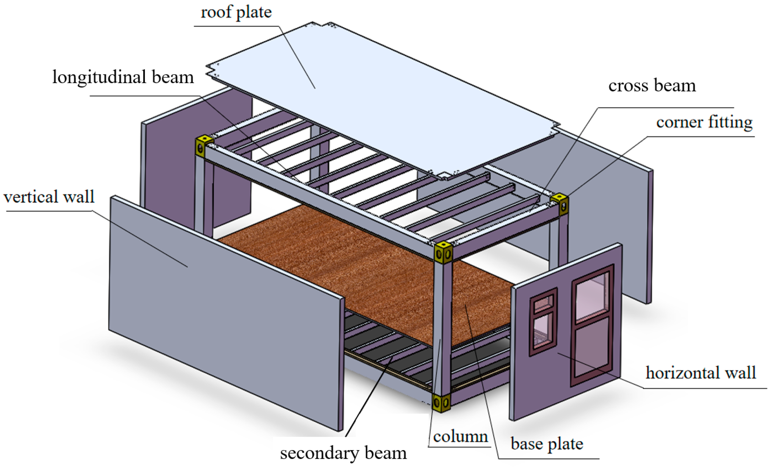
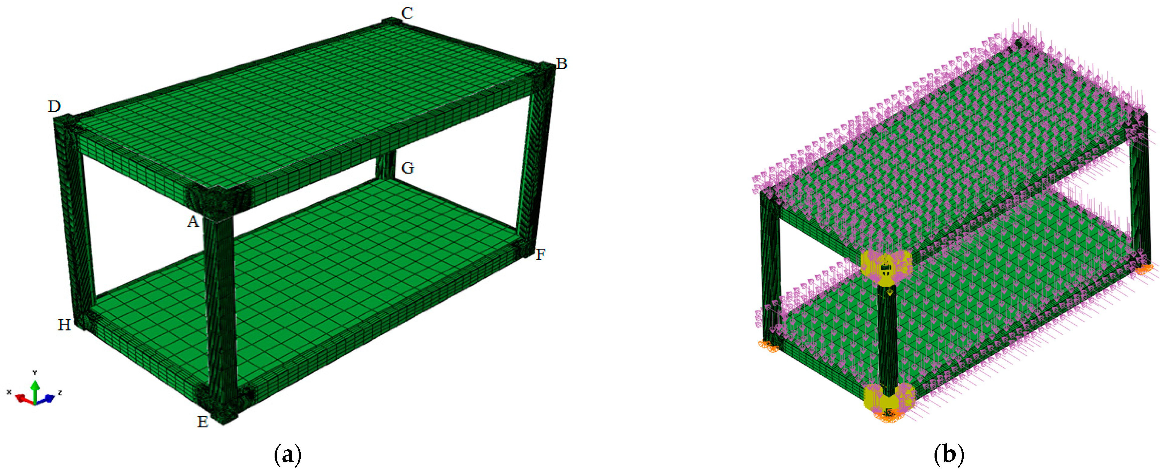
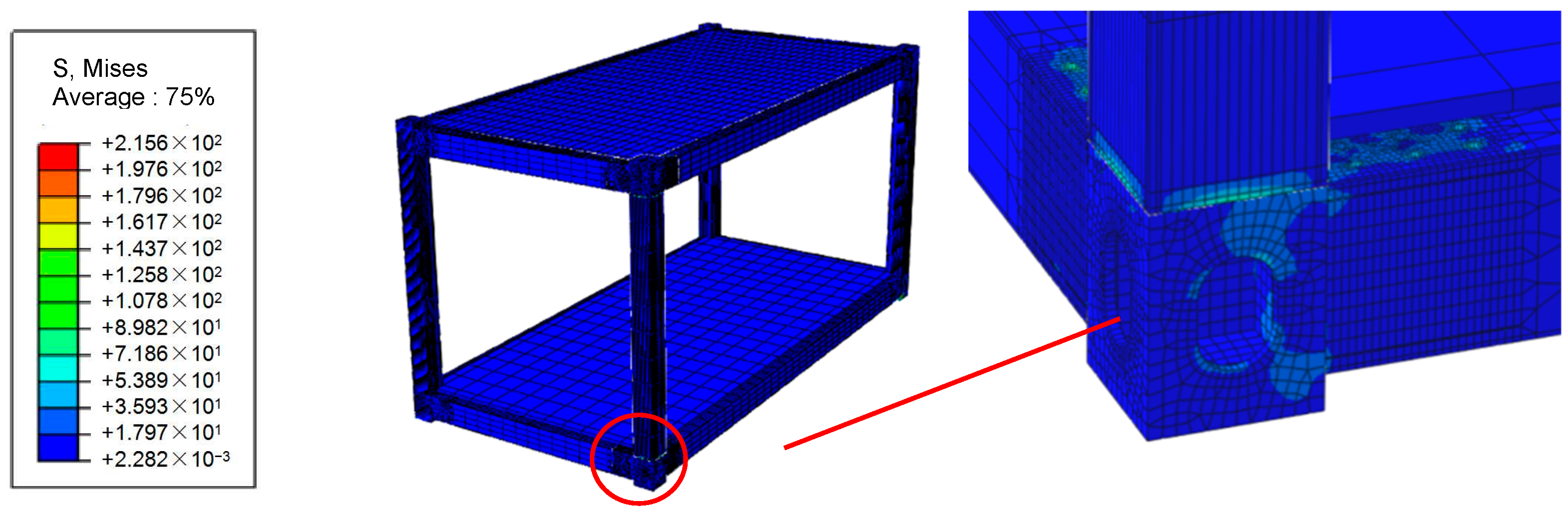
3. Structural Composition of Integrated Modular House by Flat Pack
The integrated modular house by flat pack is mainly composed of the roof system (including the roof plate, roof frame, and corner fitting), the floor system (including the base plate, floor frame, and corner fitting), corner columns, wallboard, and other components, as shown in
Figure 3.
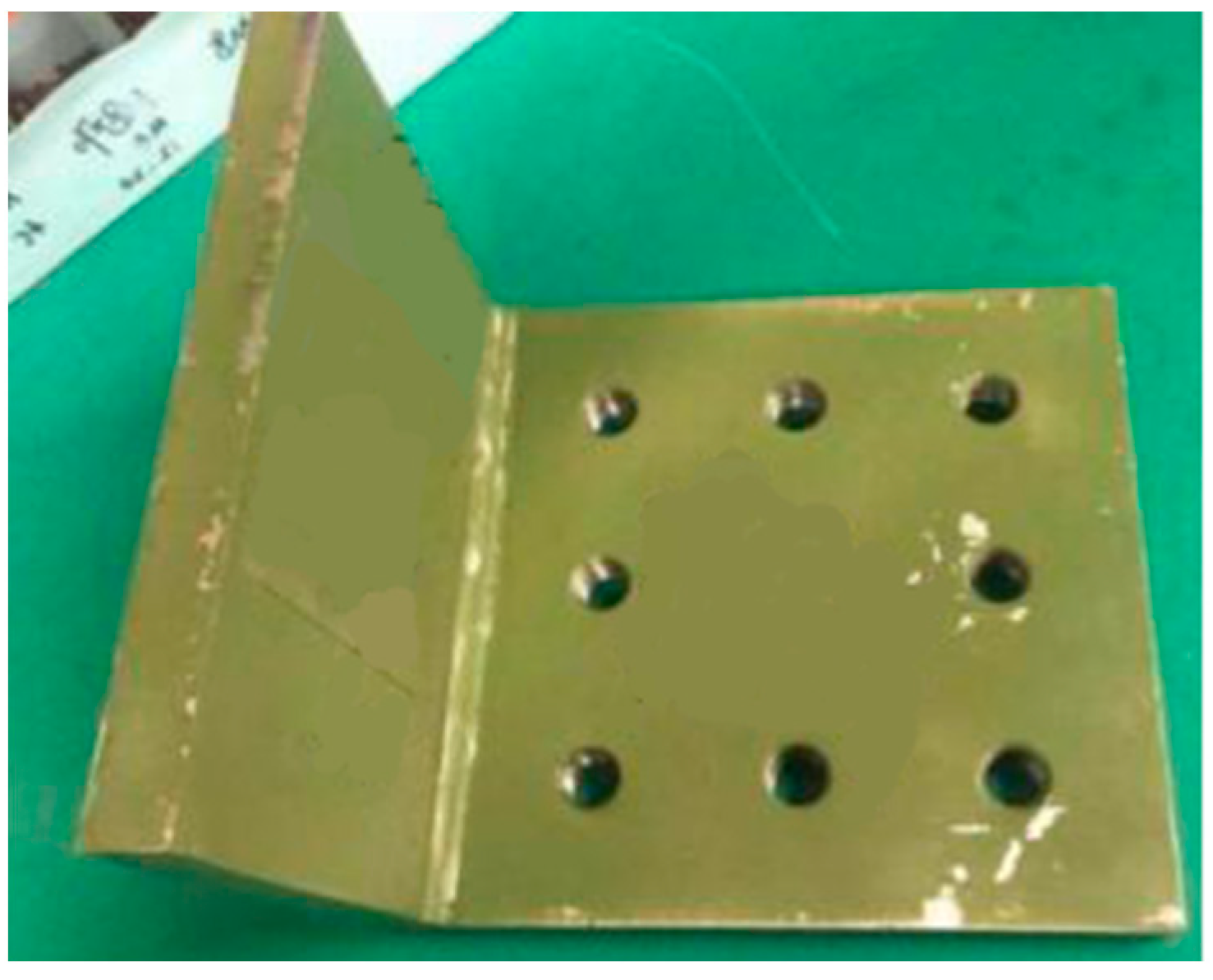
The size of the integrated modular house by flat pack studied in this work is 6000 mm × 3000 mm × 3000 mm (length × width × height). Square thin-walled steel shapes are used as vertical and cross beams and corner columns. The corner column has dimensions of 220 mm × 9 mm (width × thickness), and the cross-sectional dimensions of the longitudinal beam and cross beam of roof and floor frames are 250 mm × 150 mm × 7 mm (width × height × thickness). The sub-beams are made of channel steel with a cross-section of 120 mm × 60 mm × 7 mm (height × leg width × waist thickness). The beams, columns, and corner fitting are all made of Q345 steel, and the wall panels are made of sandwich boards with metal surfaces and polyurethane cores.
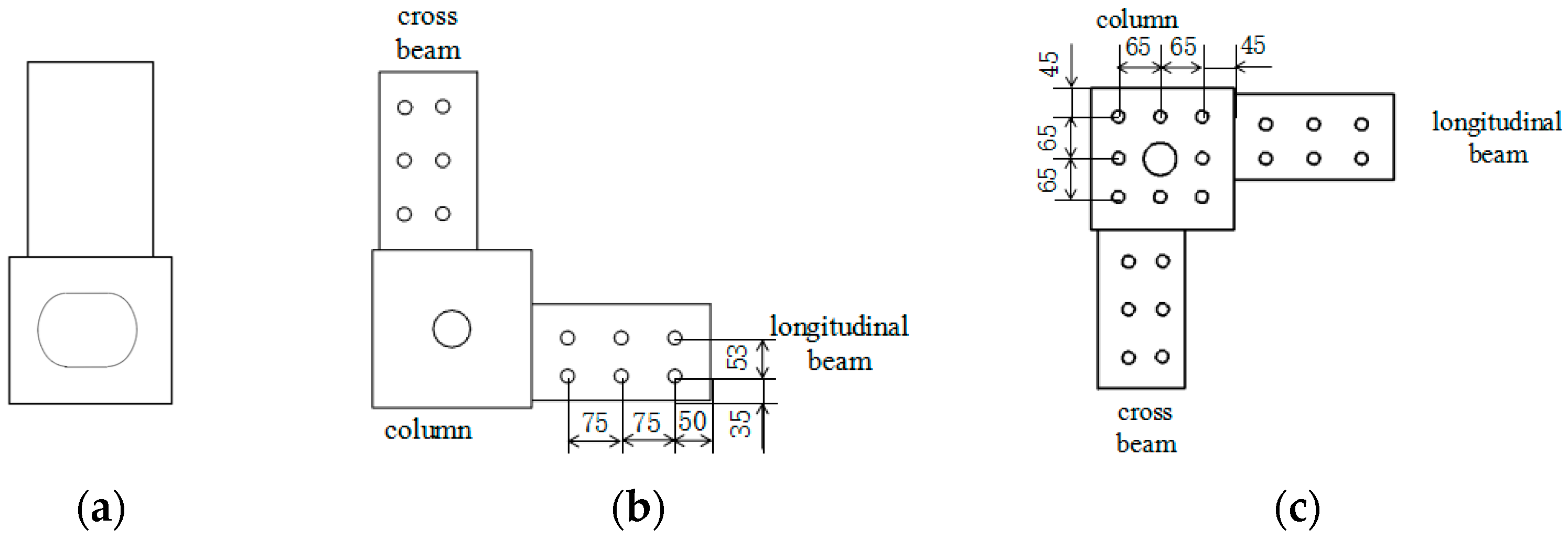
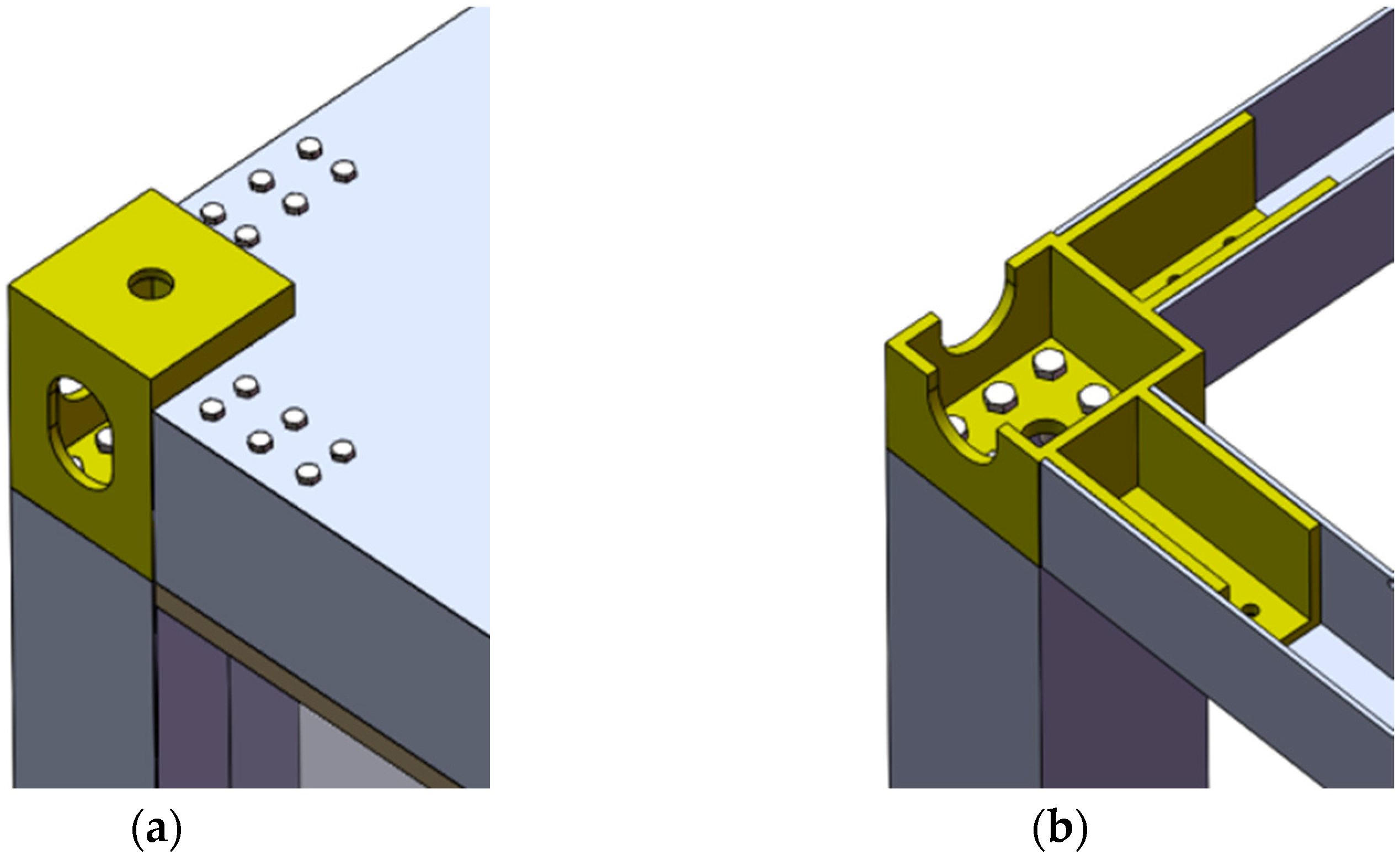
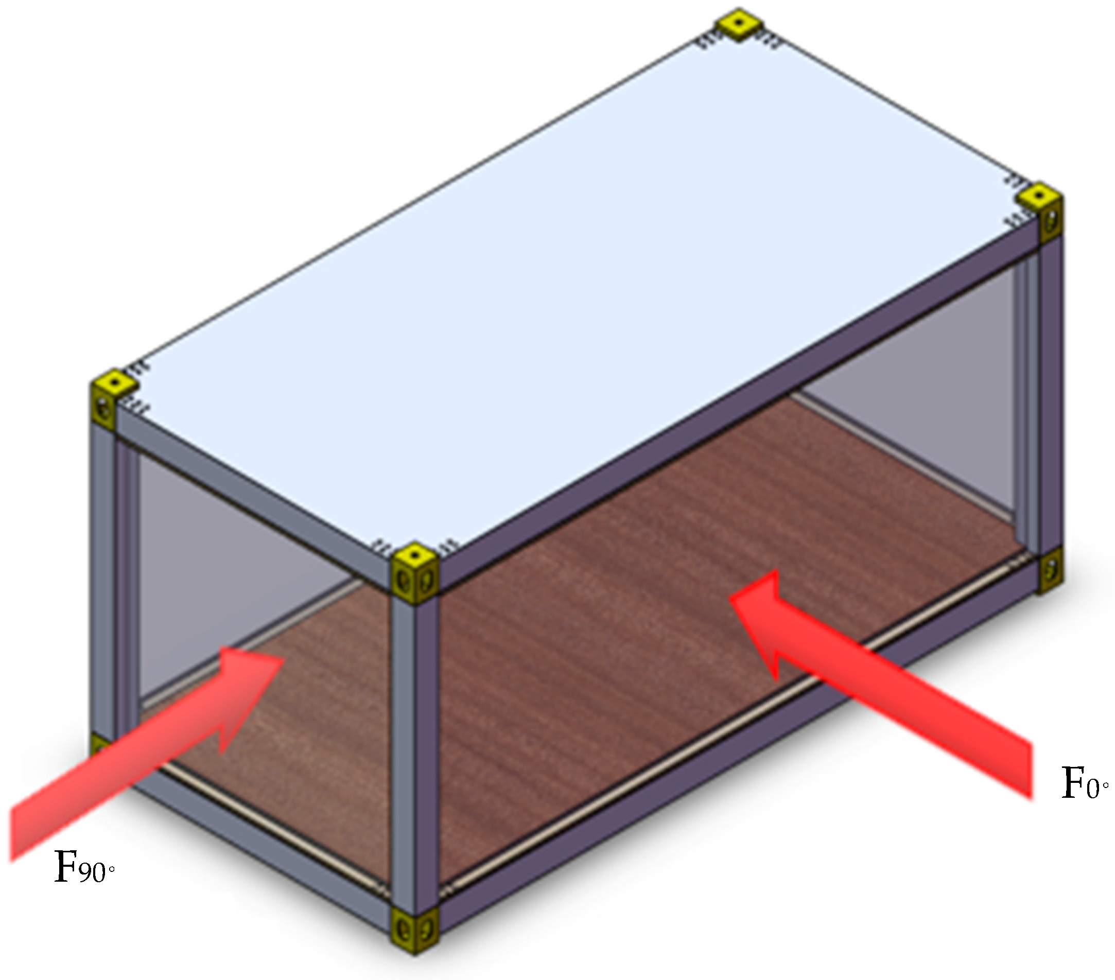
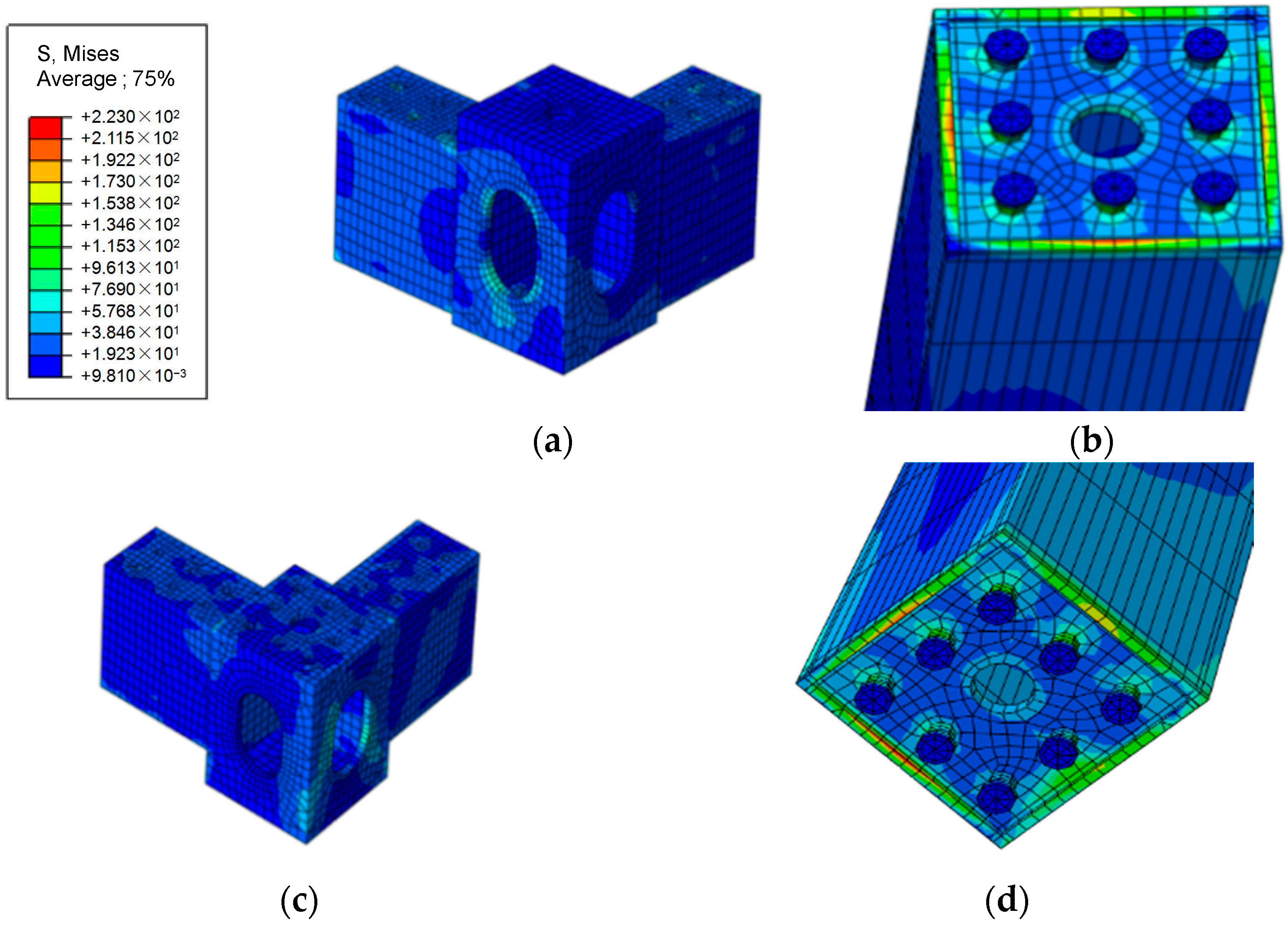
The design of the bolted connection at the corner fitting and its schematic diagram are shown in
Figure 4 and
Figure 5, respectively. The bolt holes of the corner fitting and the inner threaded holes of the corner column are fastened by eight M20 bolts (grade 8.8), and the main beam and the extension plate of the corner fitting are fastened by six M16 bolts (grade 8.8). The plate thickness of the corner fitting is 14 mm, and the length of its extension plate is 250 mm. The diameter of the bolt hole connecting the corner column is 22 mm, and the diameter of the bolt hole connecting the main beam is 18 mm. According to the design principles of “strong joint and weak member” and “strong column and weak beam”, the beam–column connection joint is the key force transfer component of the structure. Thus, the mechanical performance of those joints has a significant impact on the structure design of the house [
37,
38,
39,
40].
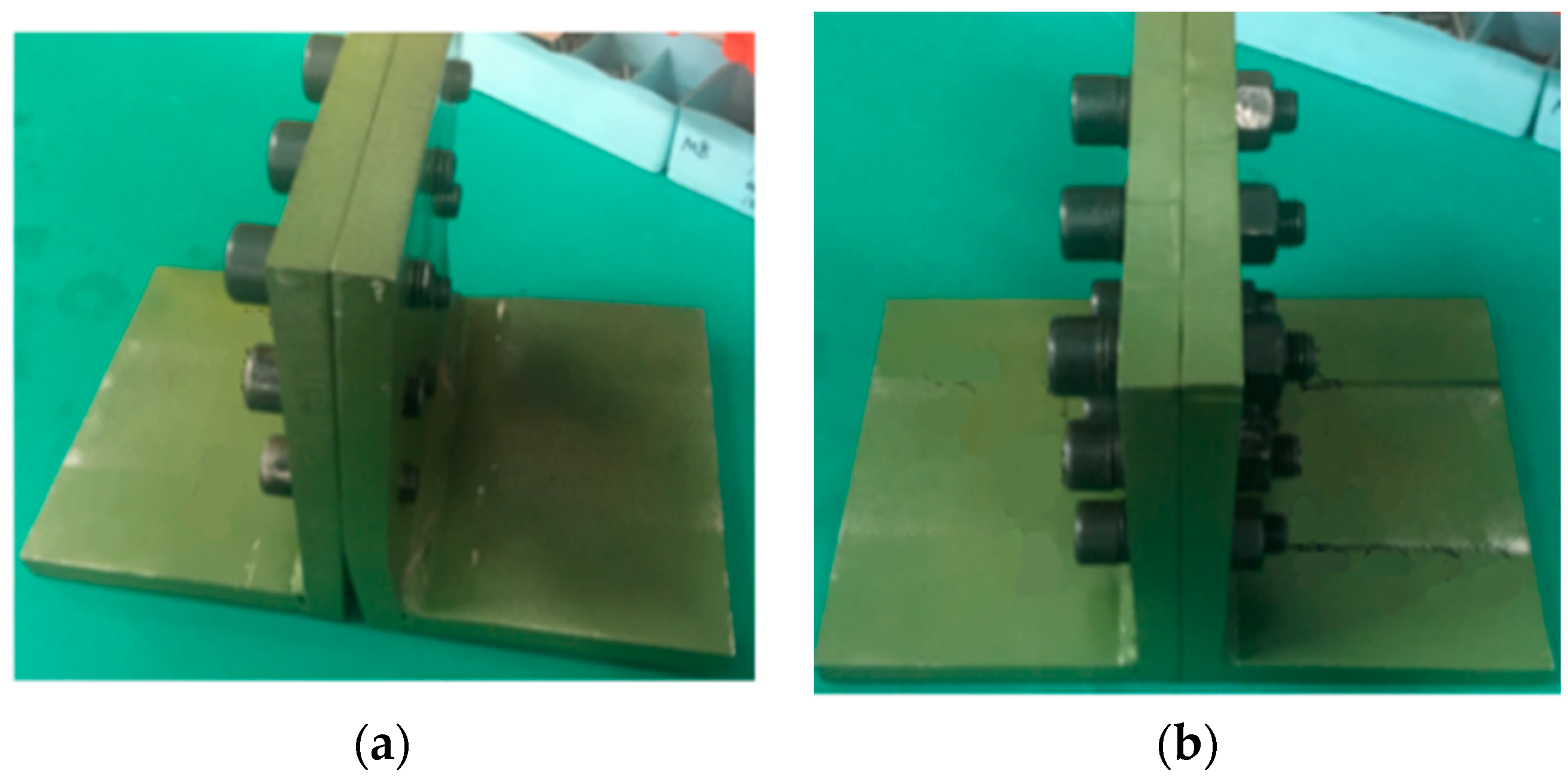
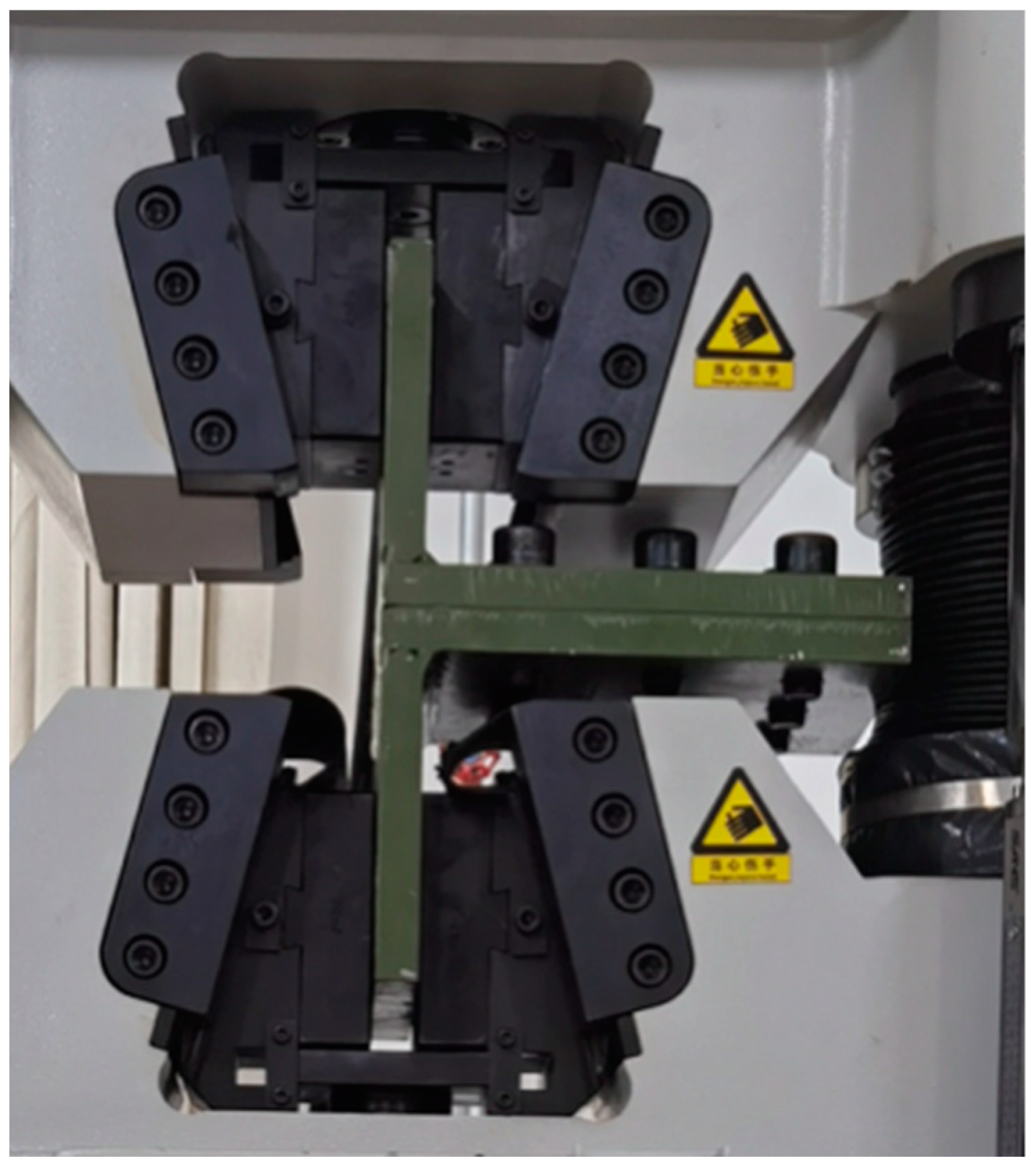
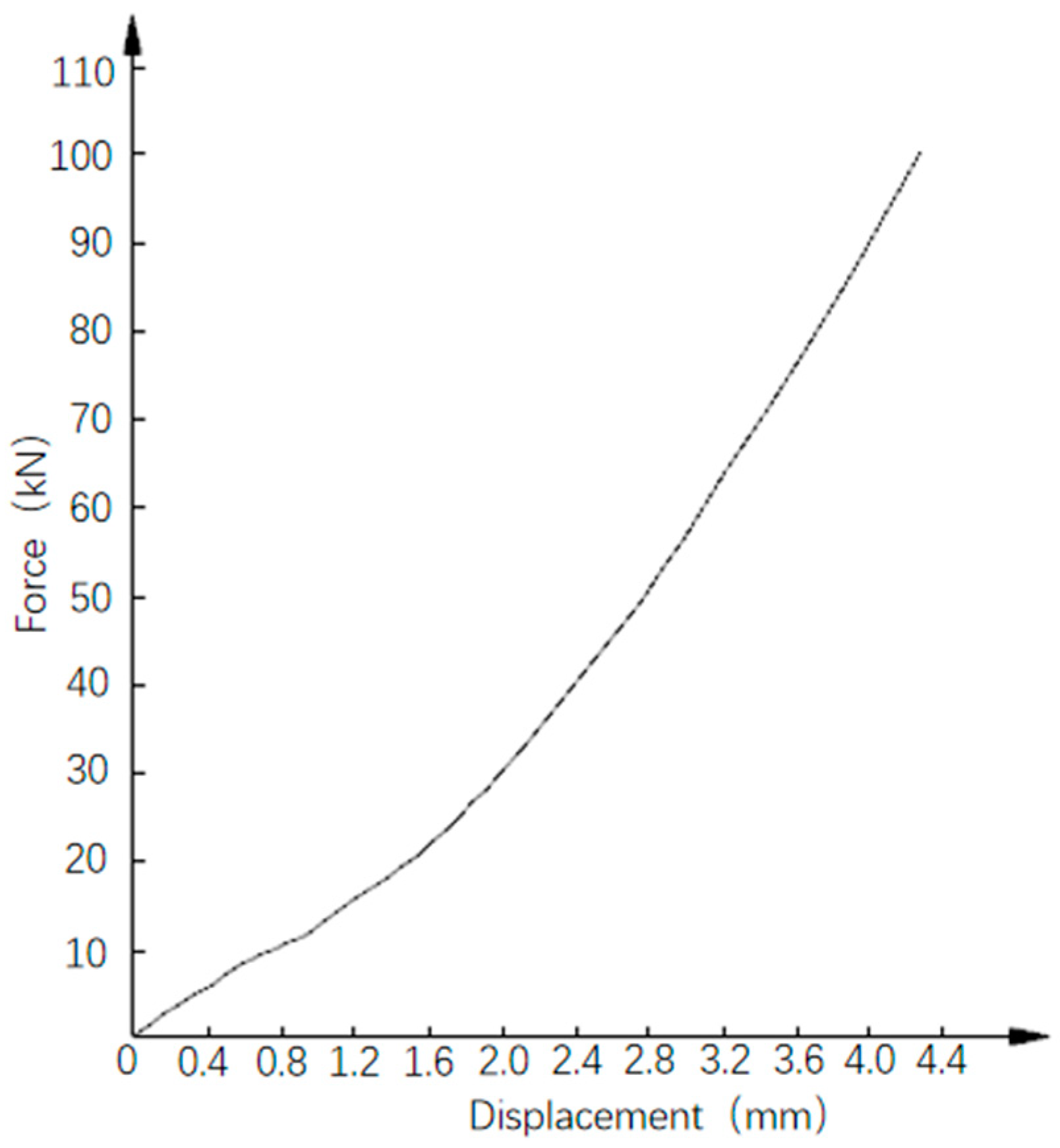
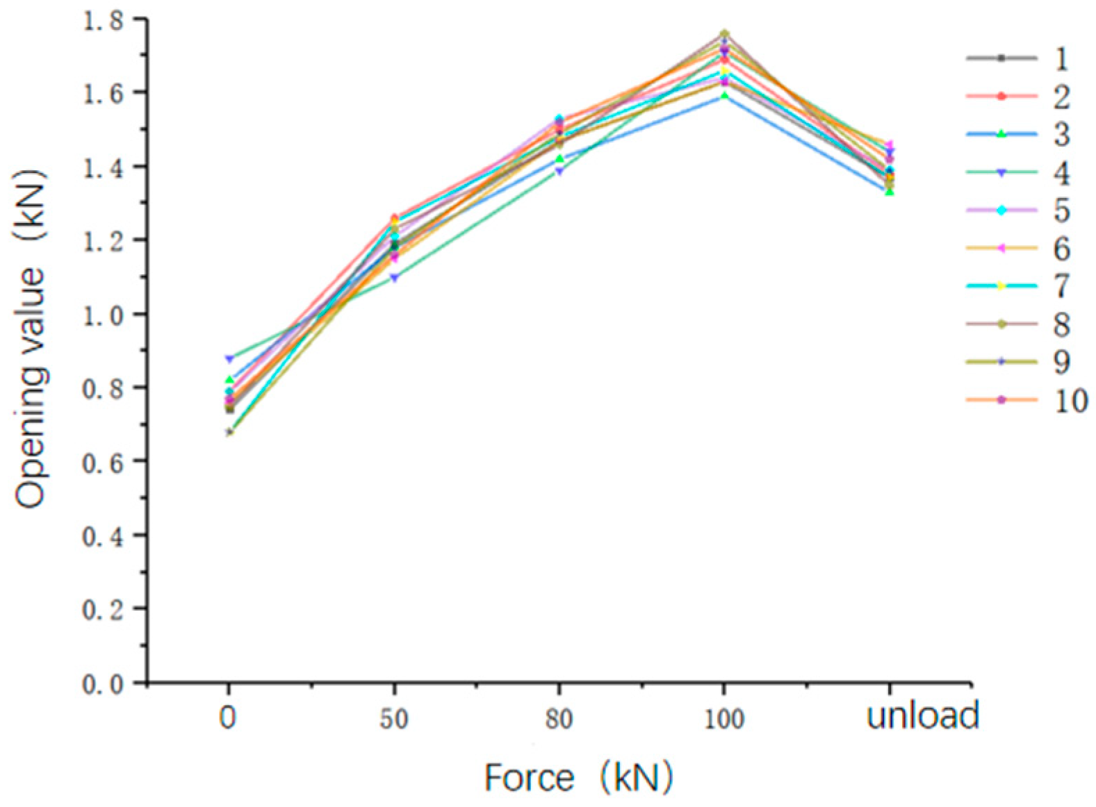
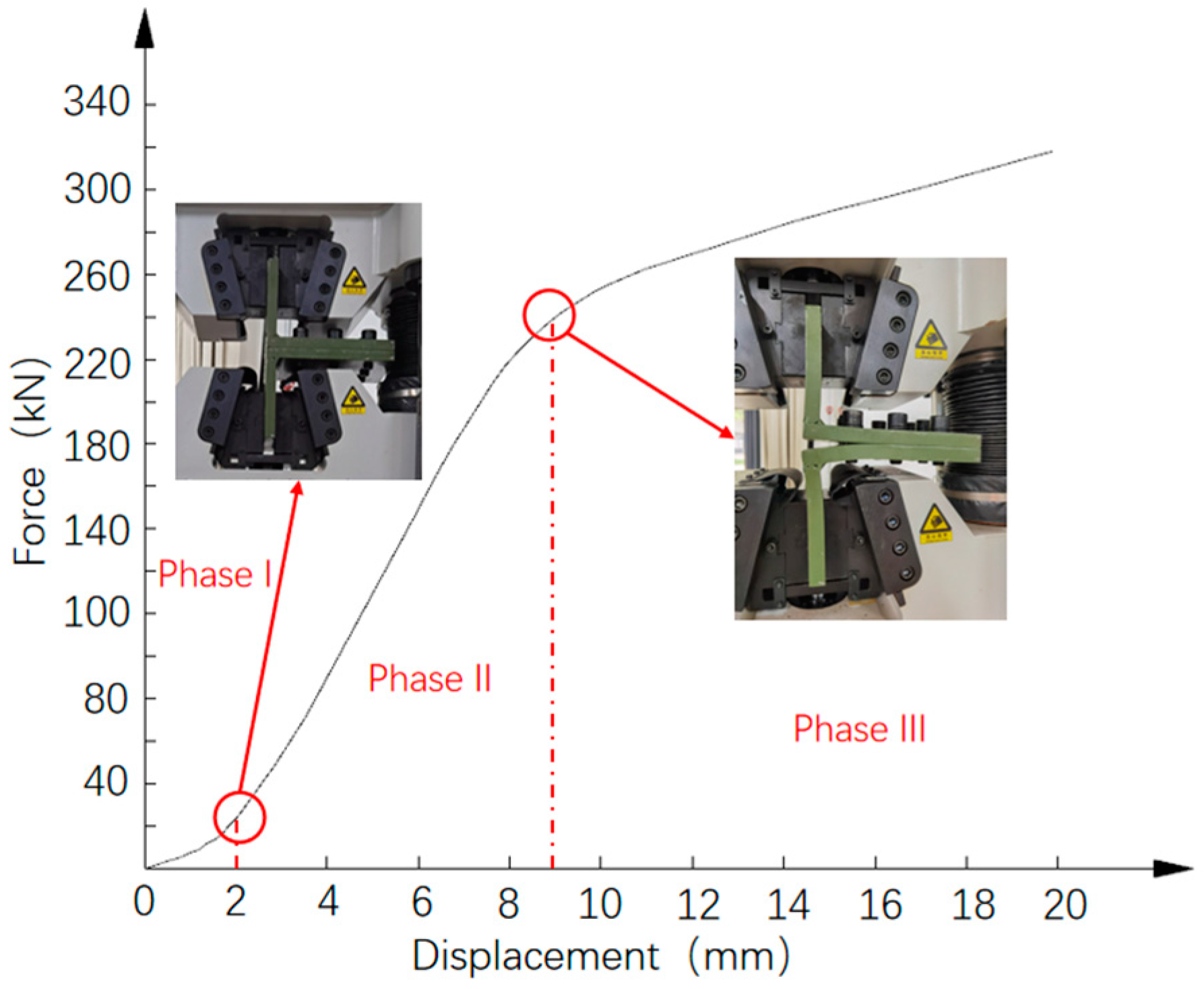
7. Results Analysis of Destructive Test
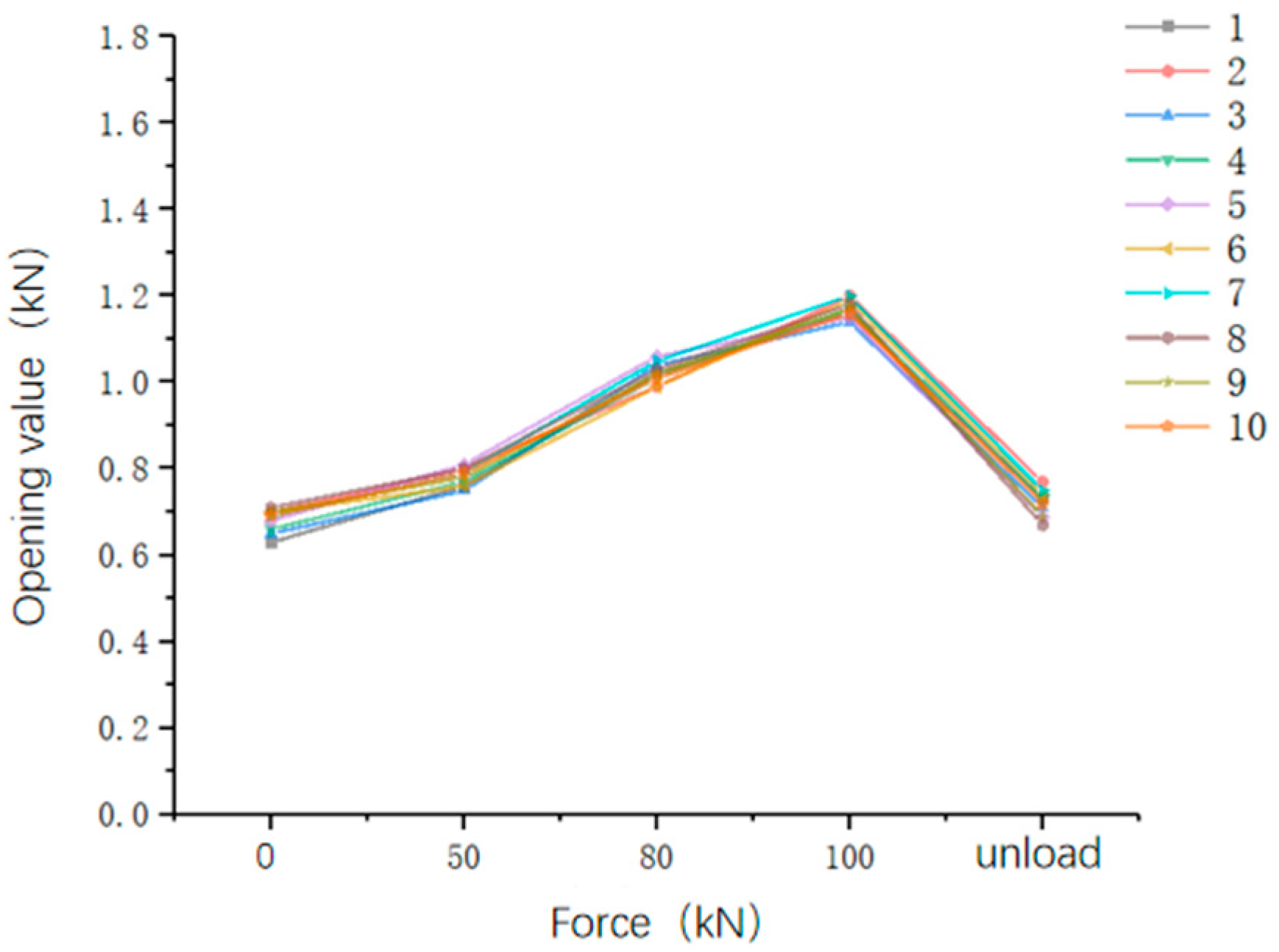
During the destructive test, the curve of displacement and force of the specimen is shown in
Figure 26. The force–displacement curve is divided into three stages. In the first stage, the displacement increases rapidly with the increase in force. To apply force, the clamp needs to overcome the assembly clearance and undergo elastic deformation while clamping the specimen.
In the second stage, the entire specimen experiences elastic deformation until the force reaches 249 kN, resulting in a maximum displacement of 9 mm. The force–displacement curve is relatively smooth, with a consistent slope and no inflection point. The third stage is the plastic deformation. When the force reaches 300 kN, the relative displacement of the L-shaped specimen reaches 16 mm. After unloading, the relative displacement decreases to 11.68 mm.
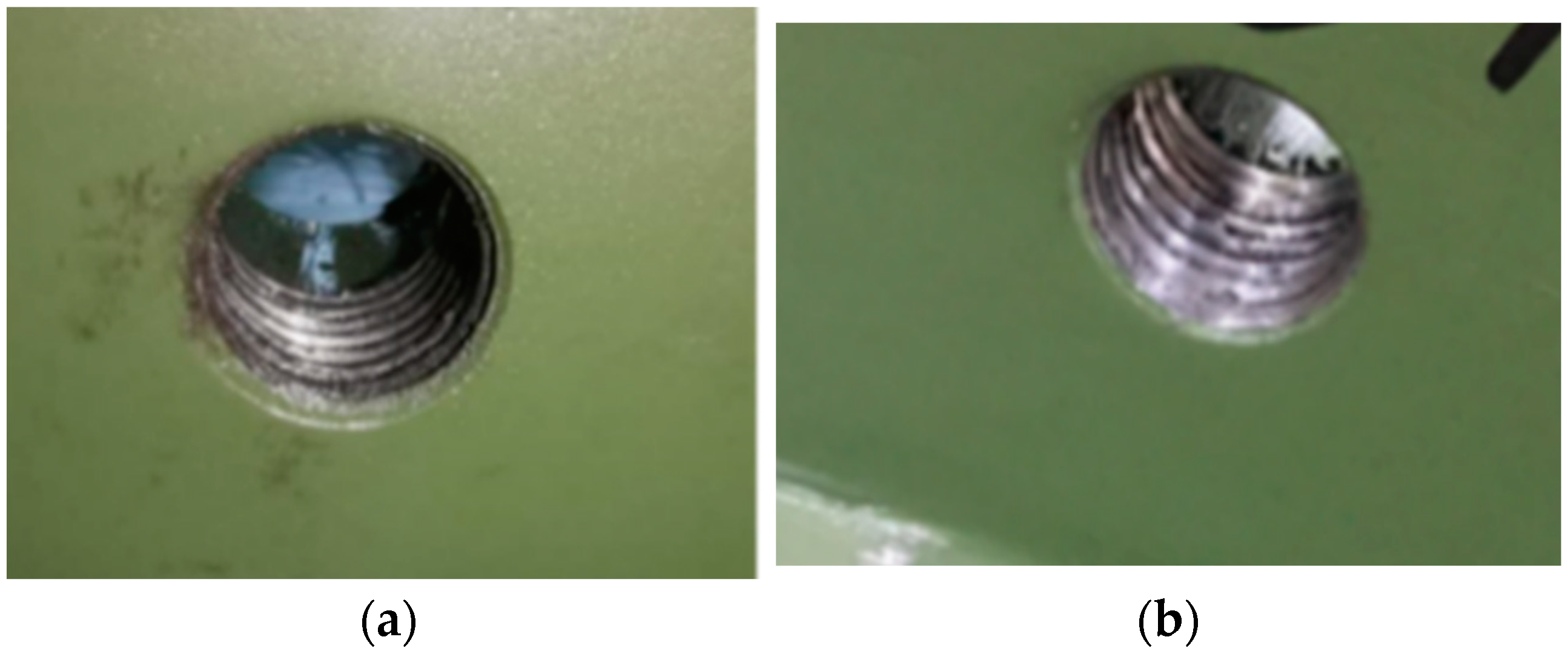
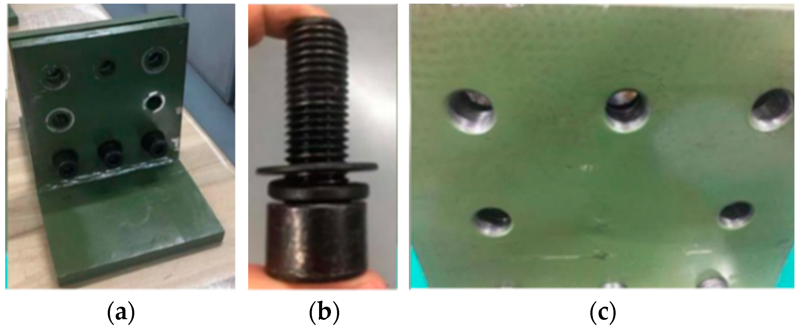
After the test, the five bolts of the specimen located far from the weld position can be removed normally, and the removed bolts and the threaded holes of the specimen are shown in
Figure 27. The bolts show no deformation, and the threaded holes show slight deformation. The plastic deformation of the specimen near the weld is severe, where the three bolts are bent, and the thread pairs are damaged, preventing normal removal.
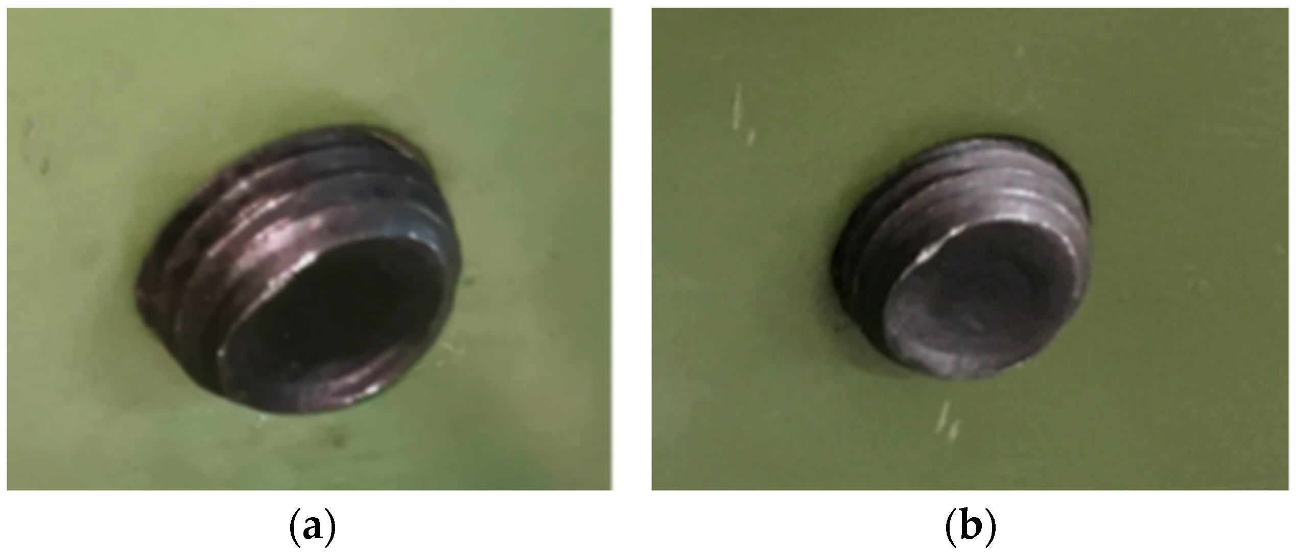
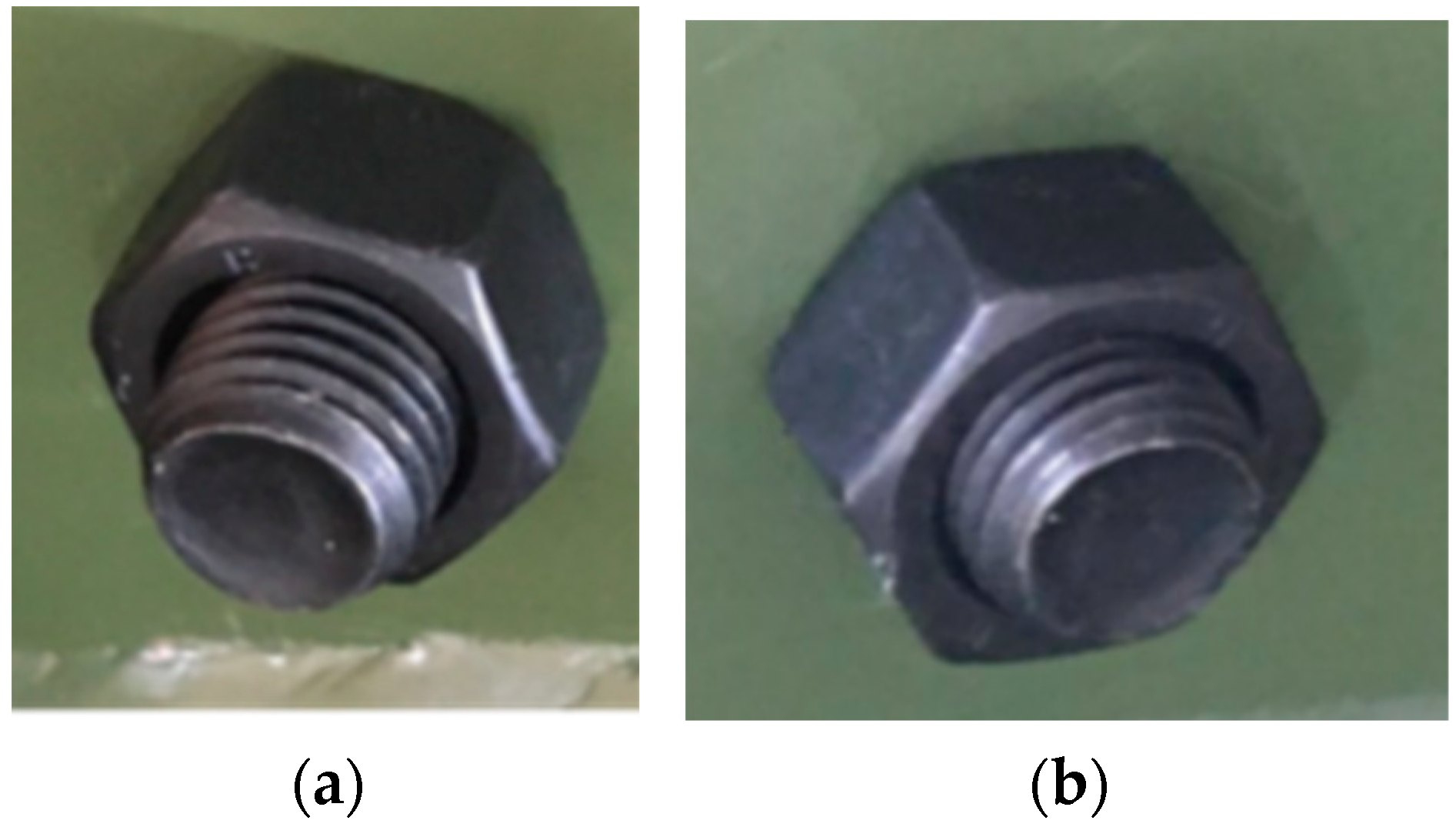
The weld of the specimen after unloading is shown in
Figure 28. Although the specimen has plastic deformation, there are no cracks or deformations in the weld region. Therefore, the weld strength ensures the connection stability and safety of the specimen under large force.


