Article

Experimental Analysis of Shear-Strengthened RC Beams with Jute and Jute–Glass Hybrid FRPs Using the EBR Technique

by
Luciana P. Maciel
1,
Paulo S. B. Leão Júnior
1,
Manoel J. M. Pereira Filho
1,
Wassim R. El Banna
1,
Roberto T. Fujiyama
2,
Maurício P. Ferreira
2 and
Aarão F. Lima Neto
1,*
1
Nucleus of Amazonian Development in Engineering, Federal University of Pará, Tucuruí 68464-000, Brazil
2
Institute of Technology, Federal University of Pará, Belém 66075-110, Brazil
*
Author to whom correspondence should be addressed.
Buildings 2024, 14(9), 2893; https://doi.org/10.3390/buildings14092893
Submission received: 13 June 2024 / Revised: 29 July 2024 / Accepted: 12 August 2024 / Published: 12 September 2024
(This article belongs to the Section Building Structures)

Abstract

:
The hybridisation of fibre-reinforced polymers (FRPs), particularly with the combination of natural and synthetic fibres, is a prominent option for their development. In the context of the construction industry, there is a notable gap in research on the use of jute and glass fibres for the strengthening of concrete structures. This paper presents comprehensive experimental results from tests on seven reinforced concrete (RC) beams strengthened for shear using synthetic, natural, and hybrid jute–glass FRP composites. The beams were reinforced using the externally bonded reinforcement (EBR) technique with U-wrap bonding. A beam without any strengthening was tested and set as a reference for the other beams. Two beams were tested with synthetic FRP shear strengthenings, one with carbon fibre-reinforced polymer (CFRP) and another with glass fibre-reinforced polymer (GFRP). The remaining tests were on RC beams strengthened with natural jute fibre-reinforced polymer (JFRP) and hybrid jute–glass FRP. The paper discusses the experimental behaviour of the tested beams in terms of vertical displacements, crack widths, and strains on steel bars, concrete, and FRP. The experimental strengths are also compared with theoretical estimates obtained using ACI 440.2R and fib Bulletin 90. The tests confirm the effectiveness of natural jute FRP and jute–glass hybrid FRP as an option for the shear strengthening of reinforced concrete beams.

1. Introduction

Strengthening reinforced concrete beams may be necessary to enhance structural performance and prolong a concrete building’s service life. The motivations for strengthening may arise from various factors, including the required increase in their load-carrying capacity, deficiencies in design and construction, operational errors, and material degradation [1]. The strengthening of a reinforced concrete beam may require increasing its cross-section in cases where it is necessary to raise its stiffness or when the strength is limited by concrete compression. The use of Fiber-Reinforced Polymers (FRPs) as Externally Bonded Reinforcement (EBR) has emerged as a prominent strengthening option when the resistance is limited by the tensile strength of the reinforcement bars [2], and they have been extensively used in reinforced concrete bridges during the 1990s [3].
In fibre-reinforced polymer composites, the polymer matrix can be strengthened with synthetic fibres such as carbon [4], glass [5], aramid [6], and basalt [7], or with natural fibres like jute, flax, sisal, kenaf, hemp, and bamboo [8,9,10]. However, it is essential to note that the total resistance of synthetic fibres may not develop fully due to the brittle failure modes associated with the use of the EBR technique [9]. Furthermore, synthetic fibres may have a significant environmental impact compared to natural fibres due to the energy consumption associated with their production [10]. Natural fibres present several advantages, including their low cost, simplicity of manufacture, non-corrosive and non-hazardous properties, renewable nature [8], and neutral CO2 emissions [10]. Among natural fibres, jute fibre is recognised for its cost-effectiveness and durability [11]. It can be easily cultivated in warm and humid climates [12], and possesses high tensile strength, good fire resistance, and reusability [13]. Moreover, there exists the potential to improve the mechanical properties of jute fibre composites by combining them with glass fibre, leading to potential cost reductions of more than 30% [14]. Figure 1 illustrates the classification of fibres in FRP and their corresponding tensile strengths.
As observed in the literature, the use of jute fibre-reinforced polymers (JFRPs) has been the focus of numerous scientific investigations for the flexural strengthening of reinforced concrete beams [22,35,36,37,38,39,40,41,42,43,44,45] and prestressed concrete beams [46]. In a few studies, JFRP has also been employed for the shear strengthening of slender reinforced concrete beams [24,35,38,47,48] and pre-damaged deep beams [49].
Ribeiro et al. [50] point out that the shear strengthening of reinforced concrete beams with a hybrid FRP with synthetic fibres is effective as the hybrid FRP improves the adhesion between FRP and concrete compared to pure FRP. In addition, Dias et al. [51] found that hybridising jute fibres with glass fibres increases the resin distribution’s homogeneity, improving the strengthening’s structural performance. Consequently, the hybridisation of glass and jute fibre-reinforced polymers (FRPs) represents a promising alternative, given the low cost and potential for recycling of glass fibre. However, there is still a lack of research on strengthening RC beams with hybrid composites of jute and glass fibres externally bonded to the concrete surface.
This paper presents and discusses the experimental results of seven tests on reinforced concrete beams carried out to investigate the performance of the shear strengthening with JFRP and jute–glass hybrid FRP. One beam without shear strengthening was tested and set as a reference for the six tests on shear-strengthened RC beams. Two beams were tested with synthetic FRP shear strengthenings, one with CFRP and another with GFRP. The other tests were on RC beams strengthened with natural JFRP and hybrid jute–glass FRP. The experimental behaviour of the tested beams is discussed in terms of vertical displacements, crack widths, and strains on steel bars, concrete, and FRP. The experimental strengths are also compared with theoretical estimates obtained using ACI 440.2R [52] and fib Bulletin 90 [53]. Figure 2 presents the fabrics used for the shear strengthening of the tested beams.

2. State of the Art: Jute Fiber-Reinforced Polymer (JFRP) as a Strengthening Material for Concrete Beams

Natural fibre composites can be formed by using plant-based or cellulose fibres extracted from leaves and barks of plants, seeds, fruits, and more, combined with a thermosetting resin matrix such as epoxy, polyester, and phenolic resin or a thermoplastic matrix like polypropylene and polyamide [10,54]. Some examples of the utilisation of these composites are in the automotive industry, military fields, packaging applications, sports equipment, biomedical fields, and the construction industry [8]. This is due to their lower density, cost-effectiveness, low energy consumption in production, neutral CO2 emissions, and zero health risks when inhaled, compared to synthetic fibres. In the construction industry, they are commonly used in producing door panels, seat backs, mattresses, carpets, and in constructing modular houses. Its application in strengthening reinforced concrete members would complement its other uses, further expanding the economic possibilities related to this material. Additionally, their use in various engineering and construction industries can promote economic growth in rural areas [10].
Difficulties in the structural application of NFRP are associated with low adhesion between the fibres and matrices [55], low mechanical strength, and a low melting temperature [56]. However, these challenges can be overcome through fibre pre-treatment [57], the introduction of additives into the matrix [58], and hybridisation [9,59]. Pre-treatment can be chemical (acetylation, alkaline treatment, enzymatic treatment, etc.) or physical (e.g., ultraviolet radiation, gamma irradiation, electron beam irradiation, plasma, and corona treatment) to enhance the adhesion between the fibre and matrix, thereby improving material strength [12]. Alternatively, heat treatment is also effective in improving the mechanical properties of NFRP [20]. Introducing additives or fillers into the matrix mixed with resin in small percentages provides a smooth finish and viscosity control [56], besides showing an increase in the modulus of elasticity and fracture toughness of the composite when using additives like silica [58]. Lastly, hybridisation involves creating composites composed of two or more constituents, such as additives and different types of fibres in the matrix [60]. Ashraf et al. [12] highlight that hybridising jute composites with synthetic fibres improved fibre/matrix adhesion, better moisture resistance, and enhanced thermal properties resulting in better mechanical and physical properties.
Furthermore, the high cellulose concentration and low microfibril angle in jute fibres make them ideal for strengthening natural fibres within polymer composites. Additionally, jute fibre is considered the most cost-effective and commercially accessible among natural fibres compared to others [61].
Structural applications have been explored in the last two decades using jute fibres in cementitious composites [61] and fibre-reinforced concrete [62,63]. These applications have shown improvements in mechanical properties and increased toughness and ductility of the material. Also, jute fibre-reinforced polymers have been applied in research for flexural strengthening of reinforced or prestressed concrete beams. The primary technique used has been externally bonded reinforcement (EBR) with hand layup applications [22,35,37,38,39,40,41,42,43,44,45,46] and laminates [36]. The FRP was applied only on the bottom face [22,37,39,41,42,43,44,45], with the beam three-sided wrapped along its full length [39,40,41,45,46], three-sided wrapped with strips in a U-shape continuously spaced along the span [35,39,40,46], or with collar-type anchoring devices at the end of the FRP [36]. This strengthening approach with jute fibre-reinforced Polymer has achieved up to a 62.5% increase in strength compared to the unstrengthened control beam [35], along with increased stiffness [37,39,43] and control over the appearance and development of cracks [35,37,46].
However, only a few studies have been conducted using JFRP for shear strengthening of concrete beams. Sen and Reddy [35] analysed the performance of FRP with jute fibre fabric treated with thermal treatment as shear strengthening for reinforced concrete beams using the EBR technique. The studied region had stirrups and U-shaped FRP in strips or continuous U-shaped FRP along the shear span, which were applied with the dry layup technique after applying a primer to the surface of the beams. The beams with continuous strengthening performed better than the JFRP strips, with a 67% increase in resistance leading to flexural failure with FRP rupture and 22% increases in strength with brittle ruins and shear cracks, respectively, compared to the unstrengthened reference beam. Alam and Riyami [24] applied strips of handcrafted unidirectional FRP with jute fibres and chemically treated them with sodium hydroxide (NaOH) and untreated jute ropes on reinforced concrete beams. The beams had stirrups and laminates made of an epoxy resin matrix with approximately 45% fibre content applied on both sides. These FRPs were bonded with epoxy adhesive to the beams using the EBR technique, with deformed bar connectors inserted into holes drilled into the surface of the beams at the ends of the laminate strips. The beams strengthened with untreated jute fibre showed better performance than the treated ones, with 36% increases for untreated jute fibre laminate and 34% for untreated jute rope laminate in strength compared to the unstrengthened reference beam, capable of changing the failure mode to flexural.
Jirawattanasomkula et al. [49] analysed the structural behaviour of pre-damaged reinforced concrete deep beams strengthened with NFRP using bidirectional jute fibre fabric and epoxy resin matrix. Using the wet layup method, the JFRP strengthening was applied in U-wrap strips along the entire length of the shear span of deep beams. The beams had stirrups in the studied shear span. The results indicated that JFRP strengthening restored the strength of the reference beam even after the damage and repair process without compromising its ductility. The best performance among the tested beams was the beam damage repaired with epoxy resin and strengthened with four layers of jute. This beam reached a 56% resistance increase compared to the reference beam. Alam and Rahman [47] analysed the behaviour of shear-strengthened beams with jute fibre laminates applied to the beam surface with or without connectors. The beams had no stirrups and were strengthened with handcrafted laminates made from jute fibres and epoxy matrix without stirrups. One of the strengthened beams had holes for connector insertion. The beams strengthened with laminates showed good strength performance when compared to the reference beam independent of the connector, with a 98% increase in the beam without a connector and a 102% increase in the beam with a connector.
Makhlouf et al. [48] tested five configurations of JFRP as shear strengthening of reinforced concrete beams. The configurations used were U-wrap strips, inclined U-wrap strips, U-wrap strips with a cap, complete wrap strips, and full-length wrap. It was observed that the full-length wrap reduces the tested beams’ vertical displacement compared to other strengthening arrangements. It also increases the shear resistance significantly by 174% compared to the reference specimen.
Finally, the literature review highlights the potential of using natural jute fibres to strengthen reinforced concrete members and the complete lack of results for reinforced concrete beams strengthened with hybrid jute–glass FRPs. However, many authors [31,64,65,66] indicate that hybridising jute FRPs with glass fibres provides optimum mechanical properties compared to pure material composites and reduces product costs.

3. Design Codes

The design guidelines presented by ACI 440.2R [52] and fib Bulletin 90 [53] were used to discuss and evaluate the experimental results. ACI considers the maximum shear resistance of a reinforced concrete beam strengthened with EBR as the sum of the concrete shear strength (VRc), the transverse reinforcement strength (VRs), and the contribution of the FRP (VRf).
For reinforced concrete beams strengthened to shear, fib considers only the sum of the components VRf and VRs in its strength prediction, limited by the crushing strength of the concrete strut (VR.max). For ACI 440.2R, the strength components VRc e VRs are estimated following the recommendations of ACI 318 [67], while for fib Bulletin 90, the values of VRs and VR.max are estimated according to the Eurocode 2 [68] recommendations. To apply a strength prediction for the reference beam according to fib bulletin 90, the equation from Eurocode 2 to estimate VRc was used. ACI 440.2R also limits the maximum shear strength provided by the sum of VRs and VRf based on the criterion defined in ACI 318 for VRs. Table 1 and Table 2 present the equations to estimate the flexural and shear strength of the tested beams. Figure 3 illustrates the parameters used in the equations of Table 1 and Table 2. This paper does not present the equations related to VRs, as the tested beams had no transverse reinforcement. Safety factors were assumed as 1.0, and the result of the average compressive strength of concrete was used in place of characteristic strength.

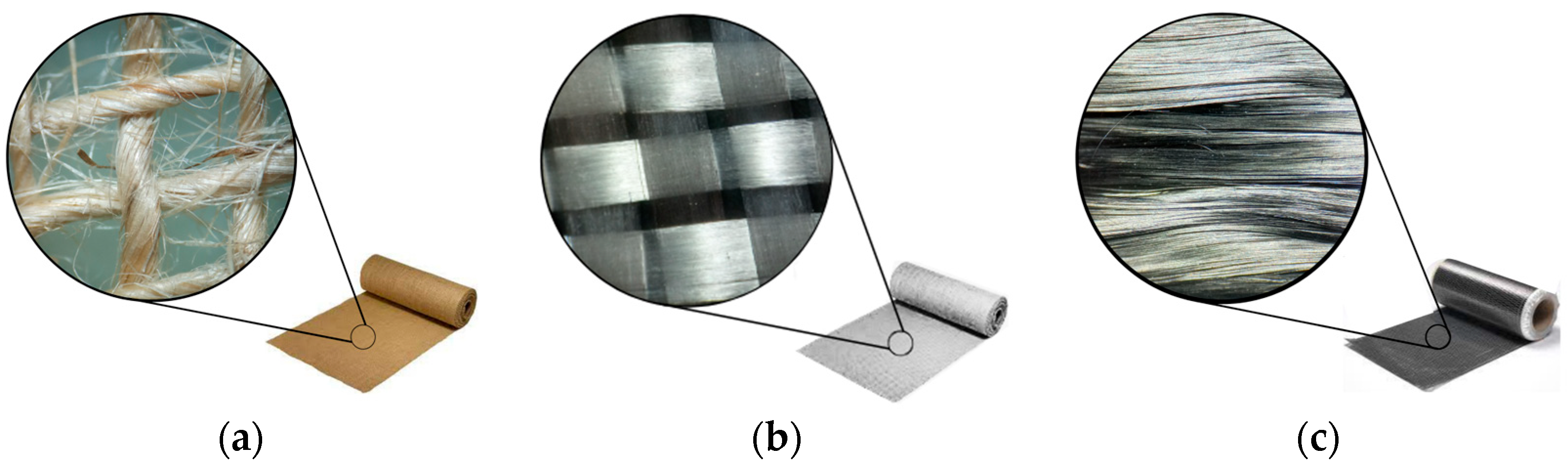
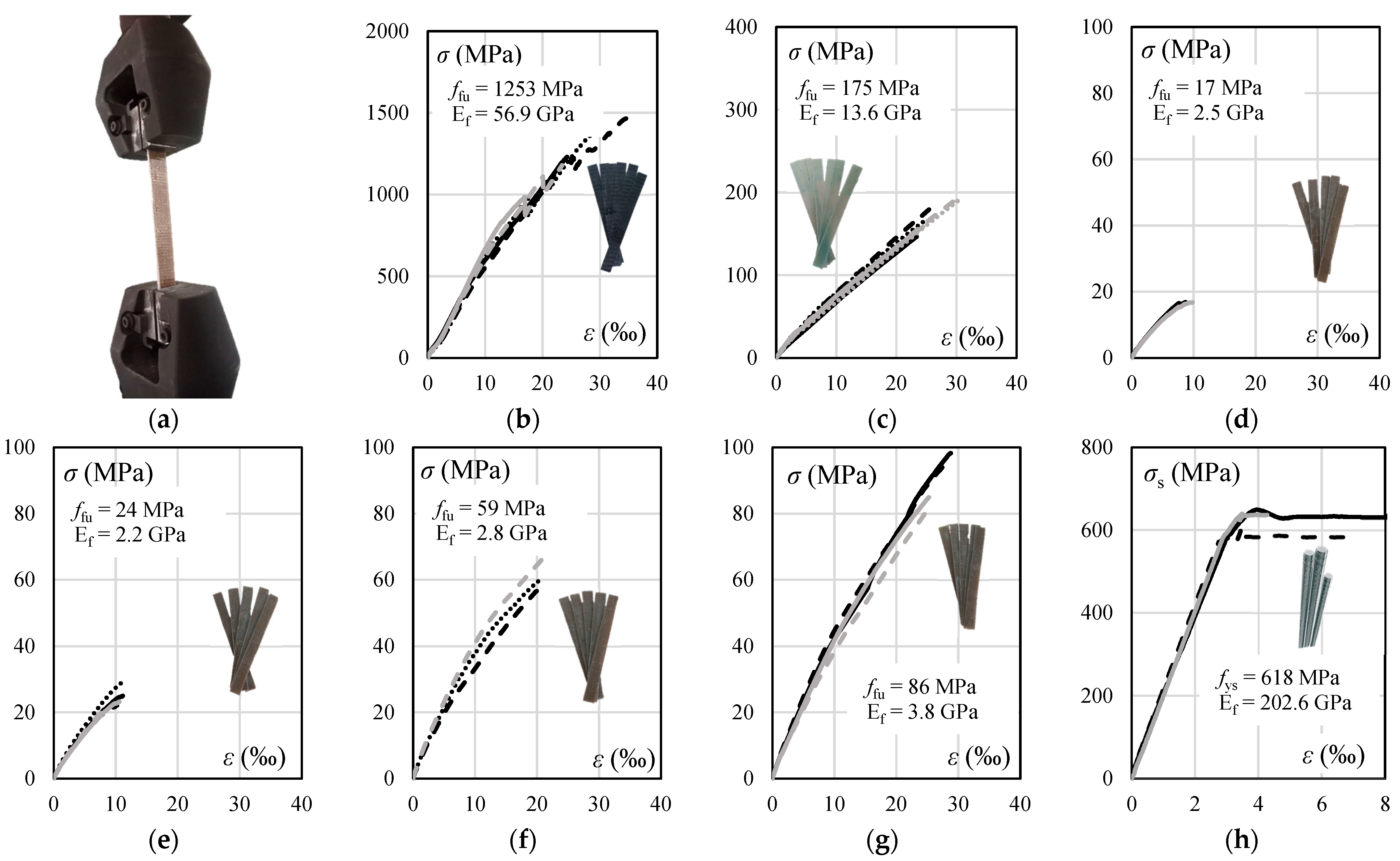
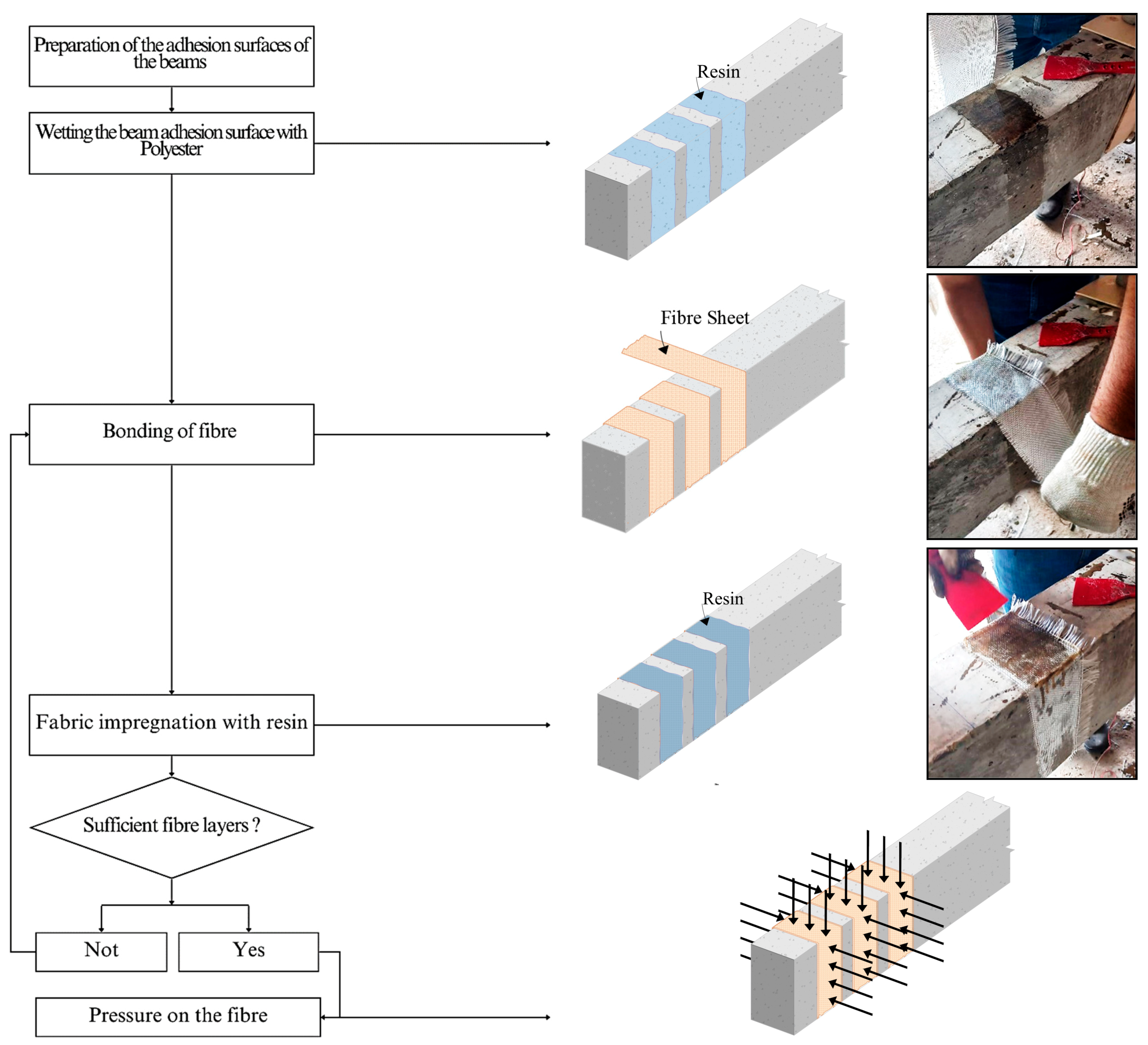
4. Experimental Program

This work presents the experimental results of tests on seven reinforced concrete beams carried out in the laboratory of the Tucuruí campus, Federal University of Pará. Six beams were strengthened to shear using different types of FRP, and one beam was set as a reference without externally bonded FRP strengthening. The beams were 2000 mm long with a clear span of 1400 mm. The beams’ cross section was rectangular with 150 mm width and 300 mm height. All the beams were tested using a three-point flexural test system employing a universal testing machine with a capacity of 3000 kN. The load was applied incrementally and continuously downwards at the midspan of the beam on a steel beam with a contact area of 150 × 200 mm2. The shear span-to-depth ratio (av/d) was greater than 2.0 to prevent arch action. A roller and a pinned support were used on each side of the beam, and a steel plate with a contact area of 150 × 150 mm2 was used.
The main variable in these tests was the type of fibre used for shear strengthening. One beam was tested without shear reinforcement (Ref. beam), while two others were strengthened with conventional synthetic FRP: one with carbon fibre (C beam) and another with glass fibre (GG beam). The first three beams were used as a reference to evaluate the performance of two beams strengthened with jute–glass hybrid composites (JGJ and GJGJ beams) and two beams with jute fibre composites (JJ and JJJ beams).
In all beams, five deformed bars with a diameter of 12.5 mm were used as flexural reinforcement in the tensile face, and two deformed bars with a diameter of 8.0 mm were placed in the compression face of the beam. The flexural reinforcement was designed to reduce the possibility of flexural failure during testing, guaranteeing the shear failures. No transverse reinforcement was used in the shear span under investigation. In the other shear span, closed stirrups with a diameter of 6.3 mm and a spacing of 150 mm were used to ensure shear failure in the region without transverse reinforcement. Figure 4 illustrates the tested beams’ geometry, test system, and reinforcement details.
The strengthening was applied in U-wrap strips, arranged perpendicular to the beam’s axis, encompassing three sides of its cross-sectional area, covering the tensile region, and extending up to the upper face of the beams. The strips were positioned along both shear spans (without and with transverse reinforcement). The U-wrap was adopted because it represents most of the practical applications of EBR FRP, as slabs are usually supported above the beams, making it unfeasible to wrap the beams’ cross-section completely. The FRP consisted of a matrix of polyester resin and fibre fabrics. In all strengthened beams, the polyester resin was thixotropic, with low viscosity, a rapid curing cycle, and high mechanical strength, with tensile strength 48 MPa, tensile modulus 4800 MPa, and maximum elongation at failure of 1.5% (commercial name: CENTERPOL L-500).
In beam C, unidirectional carbon fibre fabric with a thickness (tf) of 0.29 mm, a grammage (ω) of 320 g/m2, and a density (γ) of 3.51 g/cm3 was used. In beam GG, two bidirectional glass fibre fabric layers were employed with a tf = 0.30 mm, ω = 330 g/m2. and γ = 2.50 g/cm3. In beams JJ and JJJ, two and three layers of bidirectional jute fibre fabric with a tf = 1.30 mm, ω = 260 g/m2, and γ = 1.46 g/cm3 were used. In the beams with hybrid composites, jute and glass fibre fabrics with the mentioned characteristics were used, one with the first layer of jute, the second layer of glass, and the third layer of jute (JGJ beam), and the other with the first layer of glass, the second layer of jute, the third layer of glass, and the fourth layer of jute (GJGJ beam).
Five samples were cast for each type of FRP following the ASTM D 3039 [69] code. These tested specimens had a width of 25 mm, a length of 250 mm, and variable thickness according to the type of strengthening. They represented the FRP strengthening in terms of the fabric type and the number and order of layers. Three samples were taken from the longitudinal reinforcement to determine the yield strength, yield strain, and modulus of elasticity of the steel. All tests were carried out on a universal machine with a servo-controlled load application. Figure 5 shows the results of tests on FRP and steel samples.
The concrete was prepared using Type II Portland cement with the filler additive, washed medium sand, and coarse basalt aggregate with a maximum size of 19 mm. Six cylindrical samples measuring 100 × 200 mm were cast from the concrete for each beam to determine compressive and tensile strength, and three cylindrical samples measuring 150 × 300 mm were cast to determine the modulus of elasticity for all beams. The tests were carried out approximately six months after the day of concrete casting, during the same week of the tests of the beams, and resulted in a mean concrete compressive strength of fcm = 31.3 MPa, a mean tensile strength of concrete of fct,sp = 4.02 MPa, and a mean modulus of elasticity of concrete of Ec = 40.3 GPa.
Table 3 summarises the main characteristics of the beams, including the web width (bw), the effective depth (d), and the flexural reinforcement ratio (ρ). Both d and bw exhibit variable values since they were measured before and after concrete casting. Additionally, data related to FRP are presented, including the thickness of the FRP (tf), the number of layers of carbon, glass, and jute sheet, and the total number of sheets. Furthermore, the volume fraction of jute (Vf,J), glass (Vf,G), carbon (Vf,C), and the overall volume fraction of fibre (Vf) are provided and calculated using Equation (1). The volume fraction of fibres was calculated following the equation proposed by Dias et al. [51]. Finally, the modulus of elasticity of the FRP (Ef), the tensile strength (ft), and the width of the FRP strip applied to the beam (wf) are also shown.
V f = 1 t f n ω γ
The spacing of the FRP strips in all beams was 180 mm. The area of the strengthening strips was designed according to ACI 440.2R to provide a strength increase of ≈30% compared to the reference beam without strengthening. The FRP test specimen with glass fibre was initially moulded with only one layer of fabric. However, based on the test results, two layers were applied to strengthen the beam GG so that, according to code calculations, this beam achieved a strength increase closer to the other strengthened beams.
All beams were placed upside down to facilitate the strengthening process with externally bonded FRP. The surface of the concrete was submitted to mechanical grinding to remove impurities and fragilities, and the sharp corners were rounded to a diameter of 10 mm. After that, the concrete surface was cleaned with a cloth dampened with an alcohol solution to remove residues and dust. After surface preparation, the polyester resin was prepared following the manufacturer’s recommendations and applied to the beam’s surface. A solution of the hardener containing 1% of the mass of the matrix was added to the base resin. This was then manually mixed gently to avoid forming air bubbles until a perfectly homogeneous mixture was achieved. The FRP strips were applied using the hand layup technique.
The first layer of fabric was positioned and impregnated with the resin, and in cases with multiple layers of strengthening, this process was repeated immediately afterwards. A spatula was used to impregnate the resin and remove any air bubbles when applying each fabric layer. After applying and impregnating the last layer of fabric, an additional layer of resin was applied for fibre protection. The order of layers of sheet fibre coincides with the order in the beam nomenclature for the beams strengthened with hybrid FRP. The strengthening process occurred at an average ambient temperature of 30 °C and a relative humidity of 70%. Figure 6 illustrates all the activities involved in beam strengthening.
Figure 4 also illustrates the instrumentation of the beams. Strain gauges were used to measure the compression strains in the concrete surface at the midspan of each beam (cSG). Strain gauges were also used to measure the flexural rebars’ (sSG) tensile strains. The vertical displacements of the beam at the midspan were measured using a potentiometric linear transducer (νLVDT) supported on the beams with the aid of a yoke, which eliminates interferences from the accommodation of the testing system. The crack widths were also measured using potentiometric linear transducers fixed diagonally along the shear span, as shown in Figure 4. Figure 7 illustrates the arrangement of strain gauges on the FRP strips. One strain gauge was placed at different heights along each FRP strip (fSG), aiming to measure the maximum strain values throughout the tests.

5. Results

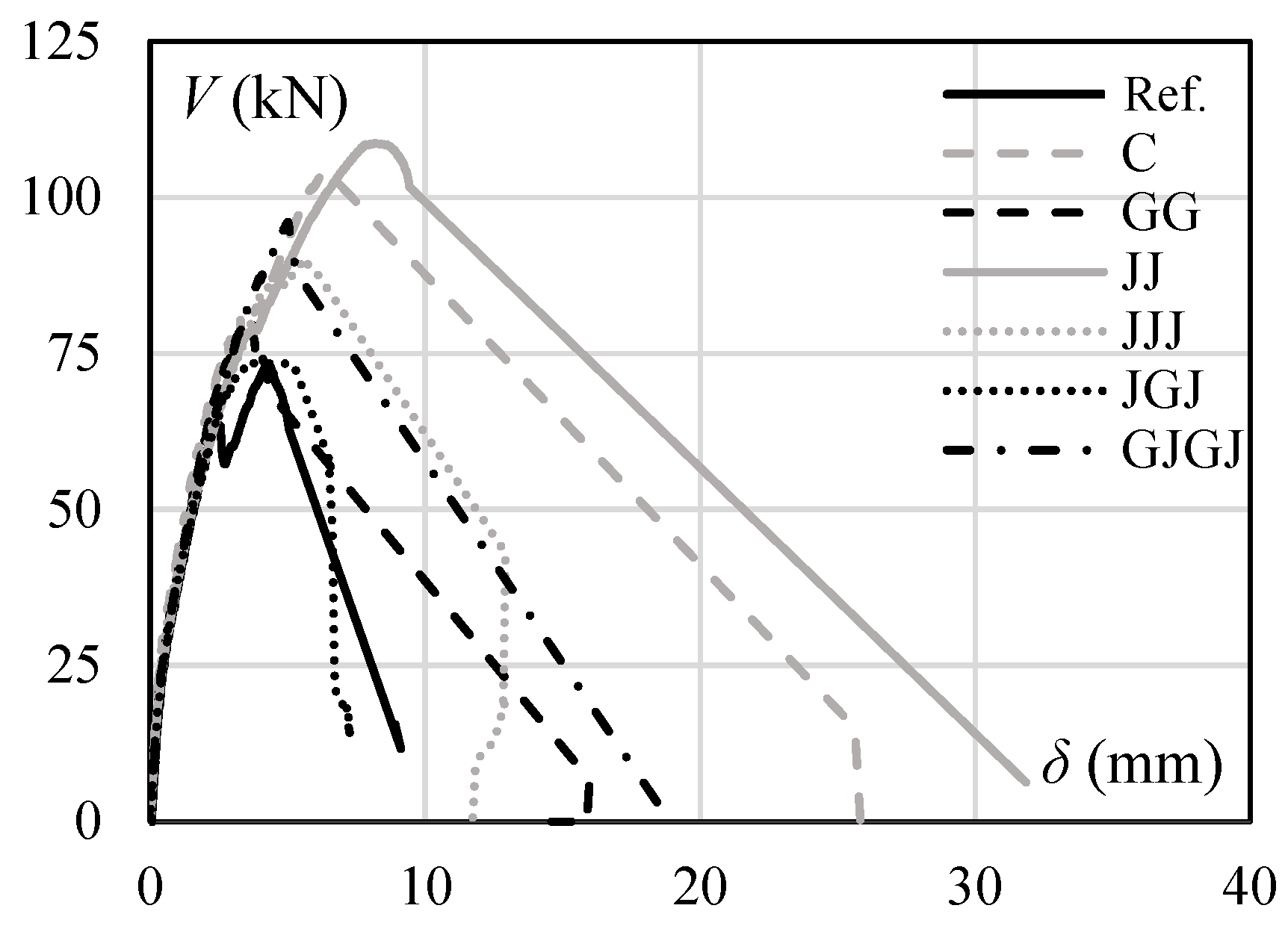
5.1. Flexural Response of the Strengthened Beams
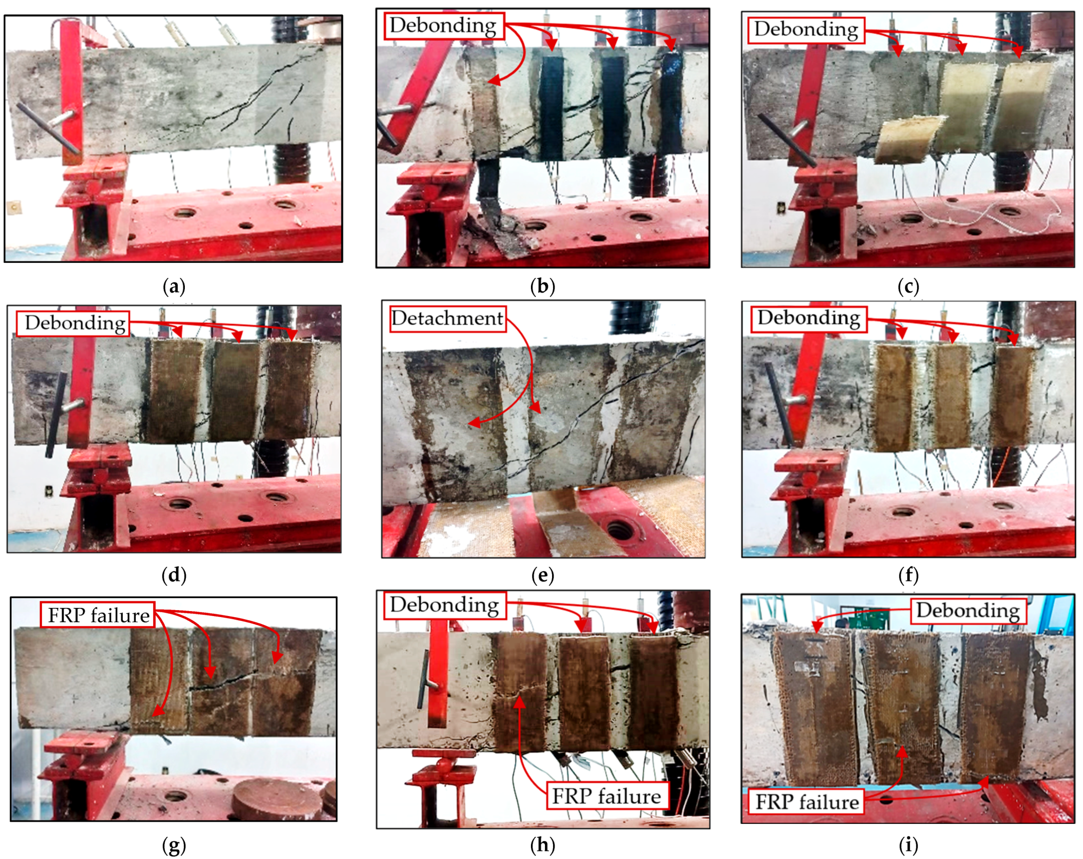
Figure 8 presents the compression strains in the concrete surface and the tensile strains in the flexural rebars. The dashed red lines represent the concrete’s assumed crushing strain (−3.50‰) and the yield strain of the flexural rebars (3.05‰). The measured strains were below the limits that would characterise that the beams reached their load-carrying flexural capacity, confirming that failure occurred due to shear.

5.2. Failure Modes

In Figure 9, the crack patterns and failure modes of each beam are shown. All beams displayed flexural cracks with small widths. Additionally, a diagonal shear crack with a large width between the support and the applied load can be observed in Figure 9 for each beam. The beams C and GG, strengthened with pure CFRP and pure GFRP, failed due to debonding in the interface between the concrete and the adhesive. In the case of the beams reinforced with glass–jute hybrids, the failure mode occurred due to a mix of partial detachment from the concrete surface and debonding from the adhesive. The failure of the JJ beam with pure jute FRP was primarily due to the rupture of the FRP strips, which was possible due to the large contact area between the FRP and the concrete and the low strength provided by the JFRP. The JJJ beam failed with the simultaneous rupture of the FRP and debonding of the adhesive. An asymmetric failure process was observed for the JJJ beam, with two strips debonding and one strip failing on one side of the beam and the opposite occurring on the other (see Figure 9h,i).

5.3. Vertical Displacements
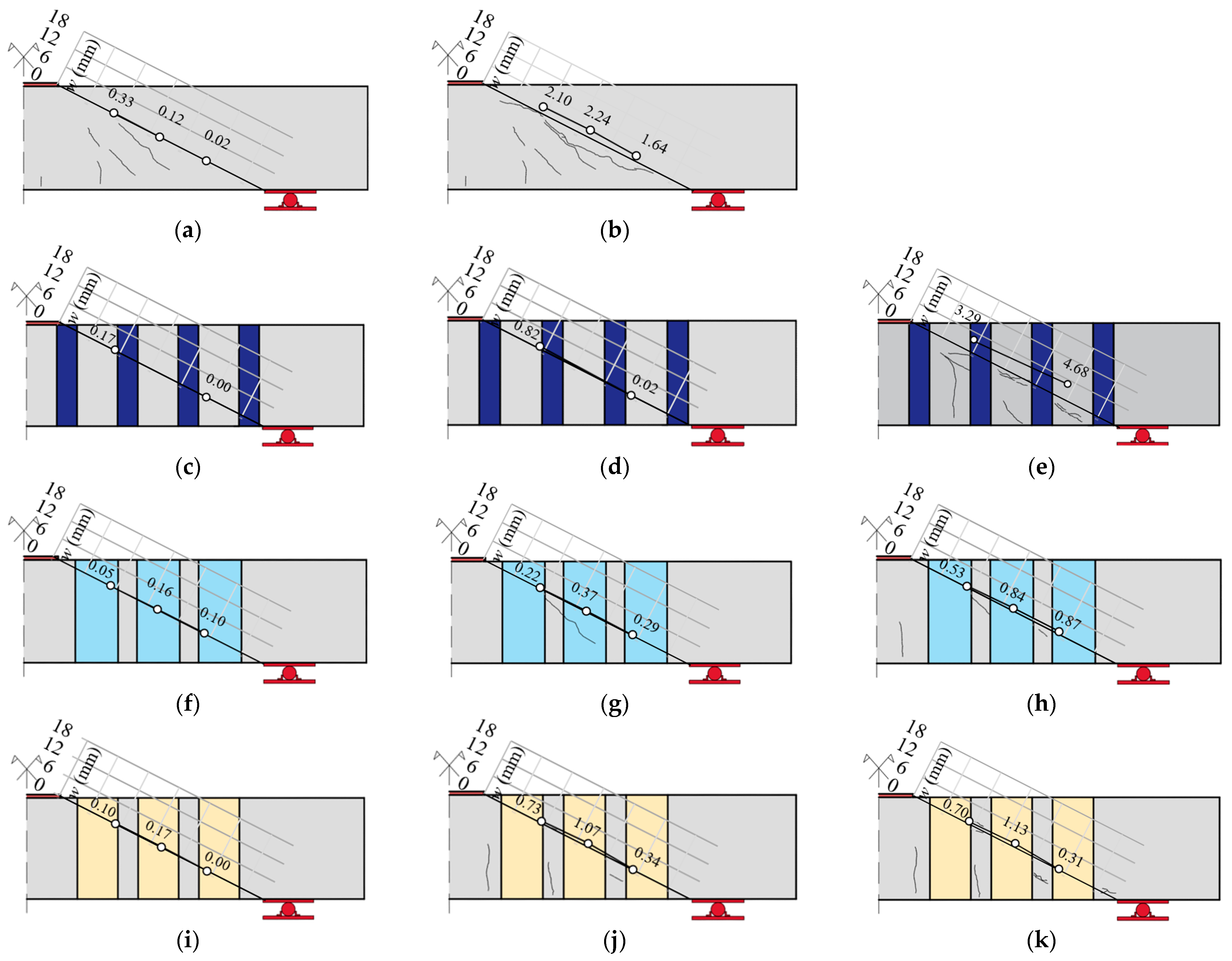
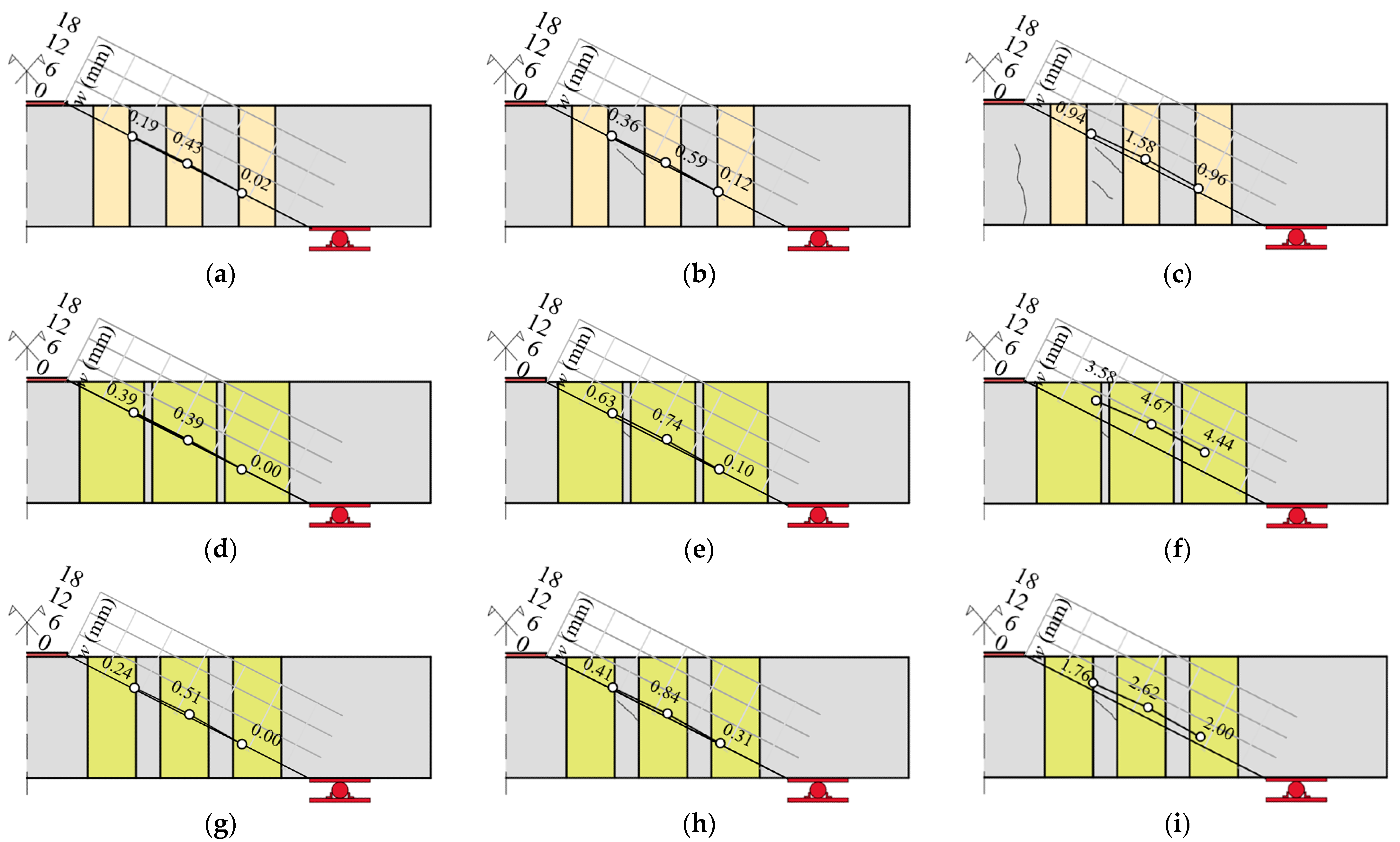
Figure 10 presents the load–displacement curves of the tested beams, where V (kN) is the applied shear force and δ (mm) is the vertical displacement measured at midspan. All beams presented brittle shear failures with small load-carrying and deformation capacity after the peak load. The reference beam (Ref.), without FRP strips, presented a load–displacement response similar to the other beams up to the formation of the critical shear crack. After that, there was a sudden reduction in shear capacity, causing a first peak loading of 64 kN. Afterwards, the beam was stabilised, and loading progressively increased until the beam reached Vu = 73.04 kN. The C beam, strengthened with carbon fibre, presented a 42.4% strength increment compared to the reference beam, and in terms of deformation capacity, it achieved 1.48 times the vertical displacement measured for the reference beam at its maximum loading.
The GG beam, which was strengthened with two layers of glass fibre, presented a smaller increase in strength compared to the C beam. This was because the strengthening layers debonded prematurely, resulting in just a 10% strength increment compared to the reference beam and a deformation capacity at the peak loading 19% lower.
The JJ beam, strengthened with two layers of jute fibre, exhibited performance similar to the C beam, with a 48.66% increase in strength and a 92.41% increase in deformation capacity compared to the Ref. beam at peak loading. The JJJ beam, reinforced with three layers of jute fibre, exhibited a 23.4% increase in shear strength compared to the reference beam. This increase was relatively lower than observed for the JJ and C beams. This indicates that the detailing strategy adopted for the JJ beam, which included a larger contact area between the FRP and concrete, was more effective and led to better structural performance for strengthening applications using jute fibre FRP strips.
The hybrid strengthening applied in JGJ was ineffective, as its strength increased by only 0.7%, and it failed at a vertical displacement 15% smaller than the reference beam. On the other hand, the GJGJ beam showed encouraging results for hybrid composites of natural and synthetic fibres, with a 31.5% increase in strength compared to the reference beam. The arrangement of the fibres may have been the main reason for the difference in performance between the strengthening techniques using hybrid composites.

5.4. Crack Width

Figure 11 illustrates the applied shear force–displacement curves of the tested beams without and with EB FRP strips strengthening. The load–displacement response is divided into three loading stages, A, B, and C. Stages A and B were defined based on the behaviour of the Ref. beam, where the first stage represents the applied shear force for which the diagonal shear crack appeared, and the second stage is related to the maximum shear force resisted by the Ref. beam. Stage C represents the maximum strength increment reached by the beams strengthened with EB FRP strips. Figure 12 and Figure 13 present the crack widths measured by the LVDT attached to the beams along the axis of the expected diagonal shear crack. The Y-axis represents the crack width, and the X-axis represents the length of the crack, taken from the support towards the applied force.
The shear strengthening with FRP did not change the crack pattern of the beams at any of the loading stages. At Stage A, the reference beam reached the SLS (Serviceability Limit State) crack width limit of 0.3 mm. At the same loading stage, beams C, GG, and JGJ presented crack widths below this limit, different from what was observed for beams GJGJ, JJ, and JJJ, whose crack widths also exceeded the SLS limit.
At Stage B, the Ref. beam had a maximum crack width of 2.24 mm, while all the strengthened beams presented smaller crack widths, with a mean value of 0.8 mm. At Stage C, beams C and JJ, which showed the highest strength increments, reached their maximum load with an approximate crack width result. Despite having a low strength increment in this stage, beams GG and JGJ exhibited better crack control than the reference beam. Beams GJGJ and JJJ had similar strength increment results, but the beam with hybrid strengthening showed better crack width control.

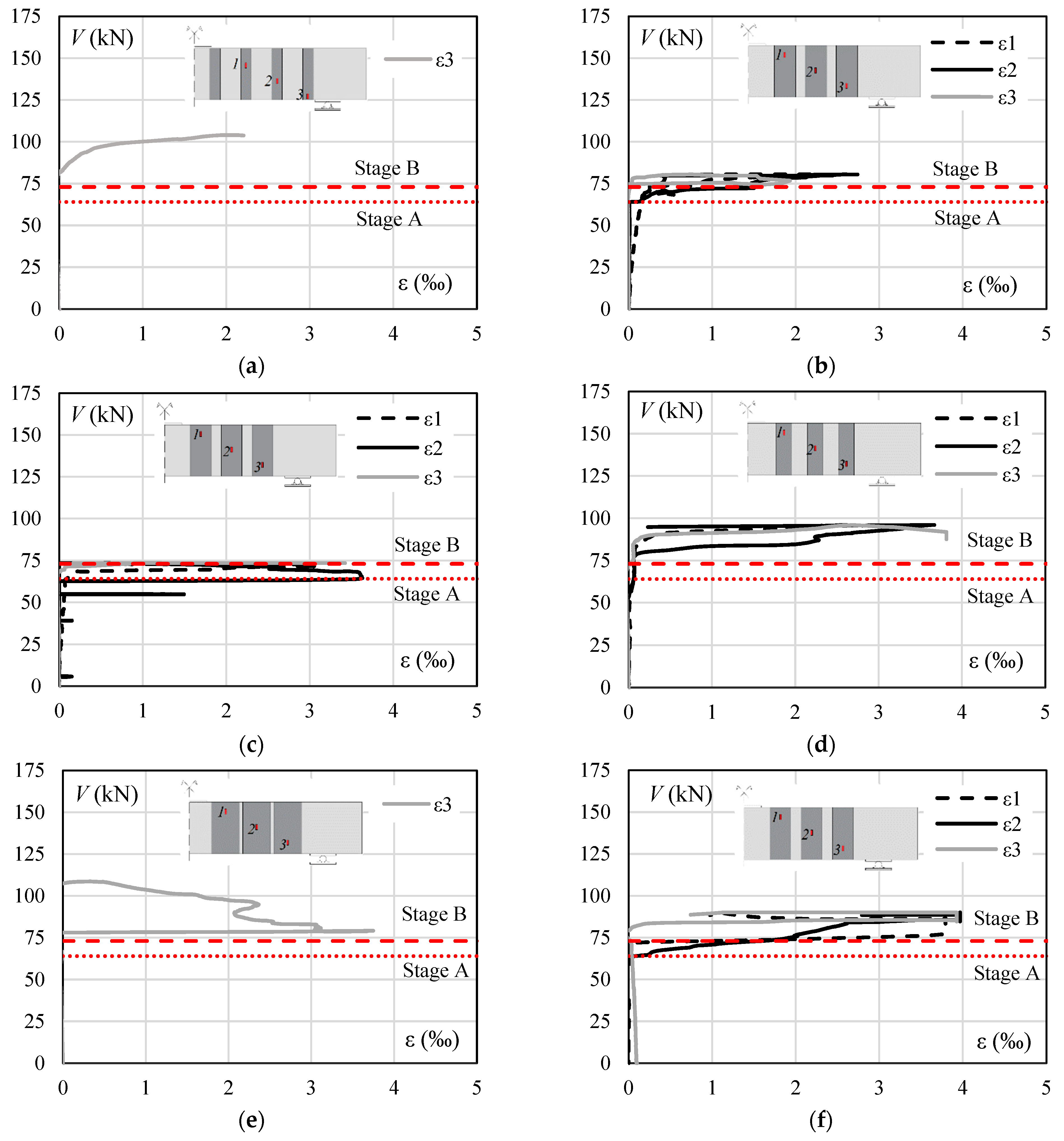
5.5. Strain in the FRP

Figure 14 presents the measured strains in the FRP strips. The red lines present results for loading stages A and B, as defined in Figure 11. The results from strain gauges ε1 and ε2 for beams C and JJ were lost. In beams C, GJGJ, and JJ, which showed a higher increase in strength compared to the reference beam, the strengthening strips were activated after the loading corresponding to Stage B. In the other beams, the FRP strips were activated at Stage A.
The FRP strips from beam GG failed due to debonding, reaching strains of up to 2.74‰, a value lower than the one calculated according to fib bulletin 90, which is approximately 3‰. In beams JGJ and GJGJ, which also failed due to debonding of the FRP strips, the maximum strains were higher than those observed in beam GG, with 3.63‰ and 3.81‰, respectively, close to the maximum strain from ACI 440.2R, of 4‰. Finally, in beam JJ, where all three strengthening strips failed, the maximum measured strain was 3.75‰, and in beam JJJ, which showed an asymmetric failure of the FRP strips, the strain was approximately 4‰.
Figure 15 presents the shear strength provided by the concrete (Vc) for each tested beam, calculated as Vc = VVf, where V is the applied shear force, and Vf is the sum of the shear strength provided by each FRP strip, taken as the sum of Vf1, Vf2, and Vf3. Vf1, Vf2, and Vf3 were calculated as the product between the strain at each FRP strip measured along the tests and the modulus of elasticity of the FRP.
This analysis could not be performed on beams C and JJ due to the loss of the strain gauges. Generally, the peak shear strength provided by concrete is similar to the maximum shear force resisted by the reference beam, thus showing a better correlation with the approach presented by ACI 440.2R than the one presented by fib Bulletin 90.

5.6. Code Results

Table 4 summarises the experimental shear strengths (Vu) and compares them with the estimates from ACI 440.2R and fib bulletin 90, along with their respective means (μ) and standard deviations (σ). This table also compares the experimental strengths with the theoretical flexural strength and estimates the shear strength provided by the FRP (Vf) by subtracting the experimental shear strength (Vu) from the failure load of the reference beam (VREF). This table also shows the effective stresses (ffe) used in the two code recommendations to estimate Vf. Figure 16 compares the experimental and theoretical results.
The design codes presented conservative strength estimates for all beams, including those strengthened with natural fibre composites and hybrid composites, which are not within the scope of the codes. Figure 17 illustrates the comparison of theoretical and experimental results of the shear strength provided by the FRP strips (Vf) and concrete (Vc). In this figure, Vc was considered equal to the strength of the reference beam. The safe side estimates from ACI were related to the conservatism of Vc. On the other hand, the excessive conservatism of fib bulletin 90 results can be explained by the fact that it totally neglects Vc in its design approach.

6. Conclusions

This research presents results from seven experimental tests evaluating the structural performance of reinforced concrete beams strengthened to shear with externally bonded fibre-reinforced polymers. These tests investigated the performance of pure jute fibre and hybrid jute and glass fibre composites compared to pure carbon and glass fibre composites. The main conclusions are:
  • Using natural jute fibres and a hybrid composite containing jute and glass fibres externally bonded to reinforced concrete beams effectively increased their shear strength and ductility;
  • Unlike beams strengthened with synthetic and hybrid EB FRP, which often exhibited premature shear failures due to the detachment or debonding of the FRP strips, beams reinforced with pure jute fibres showed a different trend. They demonstrated the potential to develop their full capacity, with shear occurring after the FRP’s tensile failure;
  • The literature review revealed limited experimental results related to using natural fibres or hybrid composites to strengthen concrete structures in shear. As some of the tested beams strengthened with hybrid composites showed premature FRP debonding failure, it is crucial to conduct further tests to thoroughly evaluate the design recommendations outlined in ACI or fib technical bulletins;
  • To confirm the efficiency of JFRP and hybrid FRP as shear reinforcements and the safety of the design recommendations, further tests should be carried out investigating FRP bond strength with concrete with different fibre combinations, shear strengthening in beams with stirrups, and different shear reinforcement ratios, as well as durability tests.

Author Contributions

L.P.M.: conceptualisation, methodology, writing—original draft preparation, formal analysis, funding acquisition; P.S.B.L.J.: methodology, writing—review and editing; M.J.M.P.F.: conceptualisation, writing—original draft preparation, writing—review and editing, validation, formal analysis; W.R.E.B.: validation, data curation; R.T.F.: Conceptualization, resources, visualisation; M.P.F.: data curation, writing—review and editing; A.F.L.N.: Conceptualization, resources, supervision, project administration, funding acquisition. All authors have read and agreed to the published version of the manuscript.

Funding

This research received no external funding.

Data Availability Statement

Some or all data that support the findings of this research are available from the corresponding author upon reasonable request.

Acknowledgments

The author would like to thank to TexiGlass and FiberTex companies for the donation of carbon fibre used in this work.

Conflicts of Interest

The authors declare no conflicts of interest.

Glossary

The following symbols are used in this paper:
avShear span of beams
bwBase width of beam
csgStrain gauges in the concrete
dBeam effective depth
fcConcrete compressive strength based on cylinder test
ffRupture stress of FRP
fsgStrain gauges in the FRP strips
fysYielding strength of steel rebar
hfHeight of FRP
leMaximum bond length
sfSpacing between strip
ssgStrain gauges in the steel rebar
wfWidth of FRP
wCrack width
AsSectional area of steel rebar
EcYoung’s modulus of concrete
EfYoung’s modulus of FRP
EsYoung’s modulus of steel rebar
VRStrengthened beam’s shear capacity
VRcThe shear strength exhibited by concrete
VRfFRP’s contribution to shear in RC beams
αAngle of FRP to the beam longitudinal axis
δDeflection
εStrain
εcuUltimate strain in concrete
εysFlexural reinforcement yielding strain
γDensity of fibres
θStrut angle relative to the longitudinal axis of the beam
ρFlexural reinforcement ratio
μAverage
νEfficiency factor for strut
σStandard deviations
ψfAdditional reduction factors for FRP shear reinforcement
ωGrammage of fibre fabric

References

  1. Ma, Y.; Lu, B.; Guo, Z.; Wang, L.; Chen, H.; Zhang, J. Limit Equilibrium Method-Based Shear Strength Prediction for Corroded Reinforced Concrete Beam with Inclined Bars. Materials 2019, 12, 1014. [Google Scholar] [CrossRef] [PubMed]
  2. Karzad, A.S.; Leblouba, M.; Al Toubat, S.; Maalej, M. Repair and Strengthening of Shear-Deficient Reinforced Concrete Beams Using Carbon Fiber Reinforced Polymer. Compos. Struct. 2019, 223, 110963. [Google Scholar] [CrossRef]
  3. Guo, S.; He, H.; Liu, C.; Cheng, S.; Liu, H. Theoretical and Experimental Study on Shearing Capacity of Concrete Beams Reinforced with Carbon Fiber Truss. Compos. Struct. 2021, 258, 113382. [Google Scholar] [CrossRef]
  4. Qi, X.; Tian, J.; Xian, G. Hydrothermal Ageing of Carbon Fiber Reinforced Polymer Composites Applied for Construction: A Review. J. Mater. Res. Technol. 2023, 27, 1017–1045. [Google Scholar] [CrossRef]
  5. Aravind, N.; Samanta, A.K.; Thanikal, J.V.; Roy, D.K.S. An Experimental Study on the Effectiveness of Externally Bonded Corrugated GFRP Laminates for Flexural Cracks of RC Beams. Constr. Build. Mater. 2017, 136, 348–360. [Google Scholar] [CrossRef]
  6. Talikoti, R.S.; Kandekar, S.B. Strength and Durability Study of Concrete Structures Using Aramid-Fiber-Reinforced Polymer. Fibers 2019, 7, 11. [Google Scholar] [CrossRef]
  7. Tang, Y.; Yao, Y.; Cang, J. Structural and Sensing Performance of RC Beams Strengthened with Prestressed Near-Surface Mounted Self-Sensing Basalt FRP Bar. Compos. Struct. 2021, 259, 113474. [Google Scholar] [CrossRef]
  8. Kamarudin, S.H.; Basri, M.S.M.; Rayung, M.; Abu, F.; Ahmad, S.; Norizan, M.N.; Osman, S.; Sarifuddin, N.; Desa, M.S.Z.M.; Abdullah, U.H.; et al. A Review on Natural Fiber Reinforced Polymer Composites (NFRPC) for Sustainable Industrial Applications. Polymers 2022, 14, 3698. [Google Scholar] [CrossRef] [PubMed]
  9. Effiong, J.U.; Ede, A.N. Experimental Investigation on the Strengthening of Reinforced Concrete Beams Using Externally Bonded and Near-Surface Mounted Natural Fibre Reinforced Polymer Composites—A Review. Materials 2022, 15, 5848. [Google Scholar] [CrossRef]
  10. Nwankwo, C.O.; Mahachi, J.; Olukanni, D.O.; Musonda, I. Natural Fibres and Biopolymers in FRP Composites for Strengthening Concrete Structures: A Mixed Review. Constr. Build. Mater. 2023, 363, 129661. [Google Scholar] [CrossRef]
  11. Islam, M.S.; Ahmed, S.J. Influence of Jute Fiber on Concrete Properties. Constr. Build. Mater. 2018, 189, 768–776. [Google Scholar] [CrossRef]
  12. Ashraf, M.A.; Zwawi, M.; Mehran, M.T.; Kanthasamy, R.; Bahadar, A. Jute Based Bio and Hybrid Composites and Their Applications. Fibers 2019, 7, 77. [Google Scholar] [CrossRef]
  13. Hossain, M.M.; Abdulla, F. Journal of Mathematics and Statistics Original Research Paper Jute Production in Bangladesh: A Time Series Analysis. J. Math. Stat. 2015, 11, 93–98. [Google Scholar] [CrossRef]
  14. Rafiquzzaman, M.; Islam, M.; Rahman, H.; Talukdar, S.; Hasan, N. Mechanical Property Evaluation of Glass–Jute Fiber Reinforced Polymer Composites. Polym. Adv. Technol. 2016, 27, 1308–1316. [Google Scholar] [CrossRef]
  15. Siddika, A.; Al Mamun, M.A.; Alyousef, R.; Amran, Y.H.M. Strengthening of Reinforced Concrete Beams by Using Fiber-Reinforced Polymer Composites: A Review. J. Build. Eng. 2019, 25, 100798. [Google Scholar] [CrossRef]
  16. Djafar-Henni, I.; Kassoul, A. Stress–Strain Model of Confined Concrete with Aramid FRP Wraps. Constr. Build. Mater. 2018, 186, 1016–1030. [Google Scholar] [CrossRef]
  17. Yao, Y.; Cui, J.; Wang, S.; Xu, L.; Li, G.; Pan, H.; Bai, X. Comparison of Tensile Properties of Carbon Fiber, Basalt Fiber and Hybrid Fiber Reinforced Composites Under Various Strain Rates. Appl. Compos. Mater. 2022, 29, 1147–1165. [Google Scholar] [CrossRef]
  18. Cervantes, I.; Aungyong, L.; Chan, K.; Ko, Y.-F.; Mendez, S. Flexural Retrofitting of Reinforced Concrete Structures Using Green Natural Fiber Reinforced Polymer Plates; California State University: Long Beach, CA, USA, 2014. [Google Scholar]
  19. Siriluk, S.; Hussin, Q.; Rattanapitikorn, W.; Pimanmas, A. Behaviours of RC deep beams strengthened in shear using hemp fiber reinforced polymer composites. GEOMATE J. 2018, 15, 89–94. [Google Scholar] [CrossRef]
  20. Jirawattanasomkul, T.; Likitlersuang, S.; Wuttiwannasak, N.; Ueda, T.; Zhang, D.; Voravutvityaruk, T. Effects of Heat Treatment on Mechanical Properties of Jute Fiber–Reinforced Polymer Composites for Concrete Confinement. J. Mater. Civil. Eng. 2020, 32, 04020363. [Google Scholar] [CrossRef]
  21. Madhavi, K.; Harshith, V.V.; Gangadhar, M.; Chethan Kumar, V.; Raghavendra, T. External Strengthening of Concrete with Natural and Synthetic Fiber Composites. Mater. Today Proc. 2020, 38, 2803–2809. [Google Scholar] [CrossRef]
  22. Chen, C.; Yang, Y.; Zhou, Y.; Xue, C.; Chen, X.; Wu, H.; Sui, L.; Li, X. Comparative Analysis of Natural Fiber Reinforced Polymer and Carbon Fiber Reinforced Polymer in Strengthening of Reinforced Concrete Beams. J. Clean. Prod. 2020, 263, 121572. [Google Scholar] [CrossRef]
  23. Xia, Y.; Xian, G.; Kafodya, I.; Li, H. Compression Behavior of Concrete Cylinders Externally by Flax Fiber Reinforced Polymer Sheets. Adv. Struct. Eng. 2014, 17, 1825–1833. [Google Scholar] [CrossRef]
  24. Alam, M.A.; Al Riyami, K. Shear Strengthening of Reinforced Concrete Beam Using Natural Fibre Reinforced Polymer Laminates. Constr. Build. Mater. 2018, 162, 683–696. [Google Scholar] [CrossRef]
  25. Hafizah, N.A.K.; Bhutta, M.A.R.; Jamaludin, M.Y.; Warid, M.H.; Ismail, M.; Rahman, M.S.; Yunus, I.; Azman, M. Kenaf Fiber Reinforced Polymer Composites for Strengthening RC Beams. J. Adv. Concr. Technol. 2014, 12, 167–177. [Google Scholar] [CrossRef]
  26. Sen, T.; Reddy, H.N.J. Flexural Strengthening of RC Beams Using Natural Sisal and Artificial Carbon and Glass Fabric Reinforced Composite System. Sustain. Cities Soc. 2014, 10, 195–206. [Google Scholar] [CrossRef]
  27. Yooprasertchai, E.; Wiwatrojanagul, P.; Pimanmas, A. A Use of Natural Sisal and Jute Fiber Composites for Seismic Retrofitting of Nonductile Rectangular Reinforced Concrete Columns. J. Build. Eng. 2022, 52, 104521. [Google Scholar] [CrossRef]
  28. Chandramohan, D.; Murali, B.; Vasantha-Srinivasan, P.; Dinesh Kumar, S. Mechanical, Moisture Absorption, and Abrasion Resistance Properties of Bamboo–Jute–Glass Fiber Composites. J. Bio Tribocorros 2019, 5, 66. [Google Scholar] [CrossRef]
  29. Chin, S.C.; Tee, K.F.; Tong, F.S.; Doh, S.I.; Gimbun, J. External Strengthening of Reinforced Concrete Beam with Opening by Bamboo Fiber Reinforced Composites. Mater. Struct. /Mater. Et Constr. 2020, 53, 141. [Google Scholar] [CrossRef]
  30. Aisyah, H.A.; Paridah, M.T.; Khalina, A.; Sapuan, S.M.; Wahab, M.S.; Berkalp, O.B.; Lee, C.H.; Lee, S.H. Effects of Fabric Counts and Weave Designs on the Properties of LaminatedWoven Kenaf/Carbon Fibre Reinforced Epoxy Hybrid Composites. Polymers 2018, 10, 1320. [Google Scholar] [CrossRef] [PubMed]
  31. Ramesh, M.; Palanikumar, K.; Reddy, K.H. Mechanical Property Evaluation of Sisal-Jute-Glass Fiber Reinforced Polyester Composites. Compos. B Eng. 2013, 48, 1–9. [Google Scholar] [CrossRef]
  32. Samanta, S.; Muralidhar, M.; singh, T.J.; Sarkar, S. Characterization of Mechanical Properties of Hybrid Bamboo/GFRP and Jute/GFRP Composites. Mater. Today Proc. 2015, 2, 1398–1405. [Google Scholar] [CrossRef]
  33. Abu Shaid Sujon, M.; Habib, M.A.; Abedin, M.Z. Experimental Investigation of the Mechanical and Water Absorption Properties on Fiber Stacking Sequence and Orientation of Jute/Carbon Epoxy Hybrid Composites. J. Mater. Res. Technol. 2020, 9, 10970–10981. [Google Scholar] [CrossRef]
  34. Ashworth, S.; Rongong, J.; Wilson, P.; Meredith, J. Mechanical and Damping Properties of Resin Transfer Moulded Jute-Carbon Hybrid Composites. Compos. B Eng. 2016, 105, 60–66. [Google Scholar] [CrossRef]
  35. Sen, T.; Jagannatha Reddy, H.N. Efficacy of Bio Derived Jute FRP Composite Based Technique for Shear Strength Retrofitting of Reinforced Concrete Beams and Its Comparative Analysis with Carbon and Glass FRP Shear Retrofitting Schemes. Sustain. Cities Soc. 2014, 13, 105–124. [Google Scholar] [CrossRef]
  36. Nouri, K.; Alam, M.A.; Jumaat, M.Z.; Muda, Z.C. Flexural Strengthening of Reinforced Concrete Beam Using Jute Rope Composite Plate. In Proceedings of the 3rd National Graduate Conference (NatGrad2015), Kajang, Malaysia, 8–9 April 2015; pp. 210–213. [Google Scholar]
  37. Ayyanar, J.; Shanmugavalli, B. Experimental Study on Flexural Behaviour of RCC Beams Using Natural Fibre Wrapping. Int. J. Eng. Sci. Comput. 2016, 6, 5252–5256. [Google Scholar]
  38. Djeddi, F.; Ghernouti, Y.; Abdelaziz, Y.; Alex, L. Strengthening in Flexure-Shear of RC Beams with Hybrid FRP Systems: Experiments and Numerical Modeling. J. Reinf. Plast. Compos. 2016, 35, 1642–1660. [Google Scholar] [CrossRef]
  39. Mallikarjuna, K.; Andotra, G. Strengthening of RC Beams Using Natural Jute Fiber Wrapping. Int. J. Sci. Prog. Res. (IJSPR) 2016, 22, 24–26. [Google Scholar]
  40. Khan, T.A.; Rahman, M.M. Behaviour of RC beams strengthened with woven jute fibers. In Proceedings of the 4th International Conference on Civil Engineering for Sustainable Development (ICCESD 2018), Khulna, Bangladesh, 9 February 2018; pp. 1–10. [Google Scholar]
  41. Joyklad, P.; Suparp, S.; Hussain, Q. Flexural Response of JFRP and BFRP Strengthened RC Beams. Int. J. Eng. Technol. 2019, 11, 203–207. [Google Scholar] [CrossRef]
  42. Salih, Y.A.; Sabeeh, N.N.; Yass, M.F.; Ahmed, A.S.; Khudhur, E.S. Concrete Beams Strengthened with Jute Fibers. Civ. Eng. J. 2019, 5, 767–776. [Google Scholar] [CrossRef]
  43. Akid, A.S.M.; Al Wasiew, Q.; Sobuz, M.H.R.; Rahman, T.; Tam, V.W.Y. Flexural Behavior of Corroded Reinforced Concrete Beam Strengthened with Jute Fiber Reinforced Polymer. Adv. Struct. Eng. 2020, 24, 1269–1282. [Google Scholar] [CrossRef]
  44. Chen, C.; Yang, Y.; Yu, J.; Yu, J.; Tan, H.; Sui, L.; Zhou, Y. Eco-Friendly and Mechanically Reliable Alternative to Synthetic FRP in Externally Bonded Strengthening of RC Beams: Natural FRP. Compos. Struct. 2020, 241, 112081. [Google Scholar] [CrossRef]
  45. Chaiyasarn, K.; Ali, N.; Phuphasuwan, P.; Poovarodom, N.; Joyklad, P.; Mohamad, H.; Zhou, M.; Hussain, Q. Flexural Behavior of Natural Hybrid Frp-Strengthened Rc Beams and Strain Measurements Using Botda. Polymers 2021, 13, 3604. [Google Scholar] [CrossRef]
  46. Archana, D.P.; Jagannatha Reddy, H.N.; Jeevan, N.; Prabhakara, R.; Aswath, M.U.; Paruti, B. Natural Jute Fibre-Reinforced Polymer Composite System for Posttensioned Beam Strengthening in Flexure. Adv. Mater. Sci. Eng. 2021, 2021, 2905150. [Google Scholar] [CrossRef]
  47. Alam, M.A.; Rahman, M.M. Shear strengthening of RC beam using jute FIBRE reinforced polymer laminate. In Proceedings of the 5th International Conference on Advances in Civil Engineering (ICACE2020), Rahman and Pal, Imam, Bangladesh, 4 March 2021; pp. SE70–SE75. [Google Scholar]
  48. Makhlouf, M.H.; Abdel-kareem, A.H.; Mohamed, M.T.; El-Gamal, A. Experimental and Numerical Study of Shear Strengthening of Reinforced Concrete Beams Using Jute Fiber Reinforced Polymers (JFRP). J. Build. Eng. 2024, 86, 108732. [Google Scholar] [CrossRef]
  49. Jirawattanasomkul, T.; Likitlersuang, S.; Wuttiwannasak, N.; Ueda, T.; Zhang, D.; Shono, M. Structural Behaviour of Pre-Damaged Reinforced Concrete Beams Strengthened with Natural Fibre Reinforced Polymer Composites. Compos. Struct. 2020, 244, 112309. [Google Scholar] [CrossRef]
  50. Ribeiro, F.; Correia, L.; Sena-Cruz, J. Hybridization in FRP Composites for Construction: State-of-the-Art Review and Trends. J. Compos. Constr. 2024, 28, 04024024. [Google Scholar] [CrossRef]
  51. da Dias, T.C.; da Silva, A.A.X.; Tonatto, M.L.P.; Amico, S.C. Experimental Investigation on the Mechanical and Physical Properties of Glass/Jute Hybrid Laminates. Polymers 2022, 14, 4742. [Google Scholar] [CrossRef]
  52. ACI Committee 440. Guide for the Design and Construction of Externally Bonded FRP Systems for Strengthening Concrete Structures (ACI 440-2R); American Concrete Institute: Farmington Hills, MI, USA, 2017; ISBN 9781945487590.
  53. Fédération Internationale du Béton. Fib Bulletin No 90: Externally Applied FRP Reinforcement For Concrete Structures; Task Group 5.1 Fiber-Reinforced Polymer Reinforcement for Concrete Structures; Fédération Internationale du Béton: Lausanne, Switzerland, 2019; Volume 242, ISBN 9782883941328. [Google Scholar]
  54. Kumar, S.; Manna, A.; Dang, R. A Review on Applications of Natural Fiber-Reinforced Composites (NFRCs). Mater. Today Proc. 2021, 50, 1632–1636. [Google Scholar] [CrossRef]
  55. Da Silva, L.J.; Panzera, T.H.; Velloso, V.R.; Christoforo, A.L.; Scarpa, F. Hybrid Polymeric Composites Reinforced with Sisal Fibres and Silica Microparticles. Compos. B Eng. 2012, 43, 3436–3444. [Google Scholar] [CrossRef]
  56. Senthilkumar, K.; Saba, N.; Rajini, N.; Chandrasekar, M.; Jawaid, M.; Siengchin, S.; Alotman, O.Y. Mechanical Properties Evaluation of Sisal Fibre Reinforced Polymer Composites: A Review. Constr. Build. Mater. 2018, 174, 713–729. [Google Scholar] [CrossRef]
  57. Pankaj; Jawalkar, C.S.; Kant, S. Critical Review on Chemical Treatment of Natural Fibers to Enhance Mechanical Properties of Bio Composites. Silicon 2022, 14, 5103–5124. [Google Scholar] [CrossRef]
  58. Rosso, P.; Ye, L.; Friedrich, K.; Sprenger, S. A Toughened Epoxy Resin by Silica Nanoparticle Reinforcement. J. Appl. Polym. Sci. 2006, 100, 1849–1855. [Google Scholar] [CrossRef]
  59. Sanjay, M.R.; Madhu, P.; Jawaid, M.; Senthamaraikannan, P.; Senthil, S.; Pradeep, S. Characterization and Properties of Natural Fiber Polymer Composites: A Comprehensive Review. J. Clean. Prod. 2018, 172, 566–581. [Google Scholar] [CrossRef]
  60. Nugraha, A.D.; Nuryanta, M.I.; Sean, L.; Budiman, K.; Kusni, M.; Muflikhun, M.A. Recent Progress on Natural Fibers Mixed with CFRP and GFRP: Properties, Characteristics, and Failure Behaviour. Polymers 2022, 14, 5138. [Google Scholar] [CrossRef] [PubMed]
  61. Song, H.; Liu, J.; He, K.; Ahmad, W. A Comprehensive Overview of Jute Fiber Reinforced Cementitious Composites. Case Stud. Constr. Mater. 2021, 15, e00724. [Google Scholar] [CrossRef]
  62. Zakaria, M.; Ahmed, M.; Hoque, M.M.; Islam, S. Scope of Using Jute Fiber for the Reinforcement of Concrete Material. Text. Cloth. Sustain. 2016, 2, 11. [Google Scholar] [CrossRef]
  63. Ahmad, J.; Arbili, M.M.; Majdi, A.; Althoey, F.; Deifalla, A.F.; Rahmawati, C. Performance of Concrete Reinforced with Jute Fibers (Natural Fibers): A Review. J. Eng. Fiber Fabr. 2022, 17, 15589250221121871. [Google Scholar] [CrossRef]
  64. Senthilrajan, S.; Venkateshwaran, N.; Naresh, K.; Velmurugan, R.; Gupta, N.K. Effects of Jute Fiber Length and Weight Percentage on Quasi-Static Flexural and Dynamic Mechanical Properties of Jute/Polyester Composites for Thin-Walled Structure Applications. Thin-Walled Struct. 2022, 179, 109719. [Google Scholar] [CrossRef]
  65. Khalid, M.Y.; Al Rashid, A.; Arif, Z.U.; Sheikh, M.F.; Arshad, H.; Nasir, M.A. Tensile Strength Evaluation of Glass/Jute Fibers Reinforced Composites: An Experimental and Numerical Approach. Results Eng. 2021, 10, 100232. [Google Scholar] [CrossRef]
  66. Ghani, M.U.; Siddique, A.; Abraha, K.G.; Yao, L.; Li, W.; Khan, M.Q.; Kim, I.-S. Performance Evaluation of Jute/Glass-Fiber-Reinforced Polybutylene Succinate (PBS) Hybrid Composites with Different Layering Configurations. Materials 2022, 15, 1055. [Google Scholar] [CrossRef] [PubMed]
  67. ACI Committee 318; Building Code Requirements for Structural Concrete (ACI 318-19). American Concrete Institute: Farmington Hills, MI, USA, 2019; Volume 623, ISBN 9781641950862.
  68. EN 1992-1-1: 2004; Eurocode 2: Design of Concrete Structures-Part 1-1: General Rules and Rules for Buildings. European Committee for Standardization: Brussels, Belgium, 2004; Volume 225.
  69. ASTM D3039; Standard Test Method for Tensile Properties of Polymer Matrix Composite Materials. American Society for Testing and Materials: West Conshohocken, PA, USA, 2000.
Figure 1. Classification of fibres used in FRP applications [15,16,17,18,19,20,21,22,23,24,25,26,27,28,29,30,31,32,33,34].
Buildings 14 02893 g001
Figure 2. Fabrics used in the beams: (a) Bidirectional jute fabric; (b) Bidirectional glass fabric; (c) Unidirectional carbon fabric.
Buildings 14 02893 g002
Figure 3. Representation of code parameters.
Buildings 14 02893 g003
Figure 4. Test System, detailing and instrumentation of the tested beams. Units in mm.
Buildings 14 02893 g004
Figure 5. Characterisation test of FRPs and flexural bars: (a) Test Setup; (b) C FRP; (c) GG FRP; (d) JJ FRP; (e) JJJ FRP; (f) JGJ FRP; (g) GJGJ FRP; (h) flexural bar.
Buildings 14 02893 g005
Figure 6. Application process of FRP to tested beams.
Buildings 14 02893 g006
Figure 7. Detailing and instrumentation of FRP strengthening: (a) C beam; (b) GG beam; (c) JGJ beam; (d) GJGJ beam; (e) JJ beam; (f) JJJ beam. Units in mm.
Buildings 14 02893 g007
Figure 8. Load strain curves in flexural reinforcement and concrete surface.
Buildings 14 02893 g008
Figure 9. Failure mode and crack pattern of the tested beams: (a) Shear failure on Ref. beam; (b) Shear failure and FRP debonding on C beam; (c) Shear failure and FRP debonding on GG beam; (d) Shear failure and FRP debonding on JGJ beam; (e) Partial concrete detachment on JGJ beam; (f) Shear failure and FRP debonding on GJGJ beam; (g) Shear failure and FRP failure on JJ beam; (h) Shear failure and FRP debonding of some layers and FRP failure on one side of JJJ beam; (i) FRP debonding of some layers and FRP failure on the other side of JJJ beam.
Buildings 14 02893 g009
Figure 10. Load deflection curves of tested beams.
Buildings 14 02893 g010
Figure 11. Applied shear force–displacement curve for the reference beam and EB FRP strengthened beams.
Buildings 14 02893 g011
Figure 12. Crack width on tested beams: (a) Ref. beam at stage A; (b) Ref. beam at stage B; (c) C beam at stage A; (d) C beam at stage B; (e) C beam at stage C; (f) GG beam at stage A; (g) GG beam at stage B; (h) GG beam at stage C; (i) JGJ beam at stage A; (j) JGJ beam at stage B; (k) JGJ beam at stage C.
Buildings 14 02893 g012
Figure 13. Crack width on tested beams (cont.): (a) GJGJ beam at stage A; (b) GJGJ beam at stage B; (c) GJGJ beam at stage C; (d) JJ beam at stage A; (e) JJ beam at stage B; (f) JJ beam at stage C; (g) JJJ beam at stage A; (h) JJJ beam at stage B; (i) JJJ beam at stage C.
Buildings 14 02893 g013
Figure 14. Load strain on the FRP: (a) C beam; (b) GG beam; (c) JGJ beam; (d) GJGJ beam; (e) JJ beam; (f) JJJ beam.
Buildings 14 02893 g014
Figure 15. Concrete and FRP strength contributions: (a) GG beam; (b) JGJ beam; (c) GJGJ beam; (d) JJJ beam.
Buildings 14 02893 g015
Figure 16. Comparison between experimental and theoretical strengths.
Buildings 14 02893 g016
Figure 17. Comparison between the experimental and theoretical results: (a) Shear strength provided by FRP strips; (b) Shear strength provided by concrete.
Buildings 14 02893 g017
Table 1. Summary of equations used to calculate the flexural strength of the tested beams.
Equations
V R . f l e x = 2 M R / L Where : M R = ρ l b w d f y d 0.5 ρ l d f y f c ; ρ l = A s b w d
Table 2. Summary of equations used to calculate the shear strength of the tested beams.
Design CodeEquations
fib V R . f i b = V R c . E C 2 for beams without shear reinforcement V R f . f i b for shear strengthened beams   with   FRP V R c . E C 2 = 0.18 k ( 100 ρ l f c ) 1 / 3 b w d V R . max V R f . f i b = A f w s f h f f f e ( cot θ + cot α ) sin α V R . max V R . max = 0.9 ν f c b w d cot θ + tan θ Where: k = 1 + 200 / d 2 ; ρ l = A s / ( b w d ) 0.02 ; ν = 0.6 ( 1 f c / 250 ) ; A f w = 2 w f t f e f f e = min ( f f b w , f f b w . c ) ; f f b w . c = k R f f u f f b w = f f b m for h f sin α l e and l e s f ( cot θ + cot α ) h f sin α 1 1 2 m s f 3 l e m n f f b m for h f sin α l e and s f ( cot θ + cot α ) l e 2 n s f f f b m 3 ( cot θ + cot α ) sin α l e for h f sin α l e and s f ( cot θ + cot α ) h f sin α f f b m = 0.25 k b β l 2 E f t f f c 2 / 3 ; l e = π 2 E f t f s 0 k τ b k ; β l = l b l e 2 l b l e i f l b < l e 1 i f l b l e k R = 0.5 ( R / 50 ) ( 2 R / 50 ) R < 50   mm 0.5 R 50   mm ; k b = ( 2 w f / s f ) / ( 1 + w f / s f ) ; h f h 0.1 d t f e = n t f for n 3 n 0.85 t f for n > 3 ; τ b k = 0.37 f c f c t for FRP strips 0.44 f c f c t for FRP sheets s 0 k = 0.20 for FRP strips 0.23 for FRP sheets ; f c t = 0.3 f c 2 / 3 for f c 50   MPa 2.12 ln ( 1 + f c / 10 ) for f c > 50   MPa m = l e ( cot θ + cot α ) sin α
ACI V R . A C I = V R c . A C I + ψ f V R f . A C I V R c . A C I = 0.66 k ρ l 1 / 3 f c b w d V R f . A C I = A f w f f e ( s i n α + cos α ) d f s f 0.66 f c b w d Where : ψ f = 0.95 for completely wrapped members 0.85 for U - wraps and two sides bonded ; k = 2 / ( 1 + 0.004 d ) 1 ; A f w = 2 w f t f ; f f e = E f ε f e ε f e = 0.004 0.75 ε f u for completely wrapped members κ e ε f u 0.004 for U - wraps and two sides bonded ; κ e = k 1 k 2 L e 11 , 900 ε f u 0.75 ; L e = 23,300 ( n t f E f ) 0.58 k 1 = f c 27 2 / 3 ; k 2 = d f L e d f for U - wraps d f 2 L e d f for two sides bonded
Table 3. Characteristics of tested beams.
Beambw (mm)d (mm)ρ (%)FRP Characteristics
tf (mm)CFRP LayersVf,C (%)GFRP LayersVf,G (%)JFRP LayersVf,J (%)FRP layersVf
(%)
Ef (GPa)ft (MPa)wf (mm)
Ref.1472671.56--0.0-0.0-0.0-0.0---
C1602711.420.6130.4-0.0-0.0130.456.91253.060
GG1452701.570.6-0.0230.7-0.0230.713.6174.8125
JGJ1522621.542.4-0.0114.823.8318.62.858.9130
GJGJ1532681.502.9-0.0212.326.3418.63.886.190
JJ1502711.512.4-0.0-0.0214.8214.82.516.7160
JJJ1612641.442.9-0.0-0.0318.4318.42.224.4120
Obs: Concrete Properties: fc = 31.3 MPa (σ = 2.8 MPa); fct,sp = 4.02 MPa; Ec = 40.3 GPa. Flexural reinforcement properties: fys = 618 GPa; Es = 202.6 GPa; εys = 3.05‰.
Table 4. Summary of experimental and theoretical strengths.
Beamd
(mm)
ρ
(%)
Vu
(kN)
Vf
(kN)
Vu/VREFVu/Vflexffe.ACI (MPa)ffe.fib (MPa)Vu/VR.ACIVu/VR.fibFailure Mode *
Ref.2671.5673.0-1.000.66 2.051.51S
C2711.42104.031.01.420.91227.6119.02.169.56S + DB
GG2701.5780.57.51.100.7254.416.61.7512.30S + DB
JGJ2621.5473.50.51.010.6711.26.01.586.14S + DB + PCD
GJGJ2681.5096.623.61.320.8715.28.42.037.58S + DB
JJ2711.51108.635.61.490.9610.01.62.3131.33S + FRP F
JJJ2641.4490.117.11.230.818.82.31.8715.84S + FRP F + DB
μ1.9612.04
σ0.259.65
Obs: Vf = VuVREF; * S = shear failure; DB = FRP debonding; PCD = partial concrete detachment; FRP F = FRP failure.
Disclaimer/Publisher’s Note: The statements, opinions and data contained in all publications are solely those of the individual author(s) and contributor(s) and not of MDPI and/or the editor(s). MDPI and/or the editor(s) disclaim responsibility for any injury to people or property resulting from any ideas, methods, instructions or products referred to in the content.

