Article

Comparative Analysis of the Performance and Study of the Effective Anchorage Length of Semi-Grouted and Fully-Grouted Sleeve Connection

by
Fenfang Yin
1,2,*,
Shiping Yin
2,
Linglei Zhang
1 and
Yonggang Xu
3
1
Jiangsu Vocational Institute of Architectural Technology, Jiangsu Collaborative Innovation Center for Building Energy Saving and Construct Technology, Xuzhou 221116, China
2
State Key Laboratory for Geomechanics & Deep Underground Engineering, China University of Mining and Technology, Xuzhou 221116, China
3
China Railway Construction Bridge Engineering Bureau Group First Engineering Co., Ltd., Dalian 116000, China
*
Author to whom correspondence should be addressed.
Buildings 2024, 14(9), 2977; https://doi.org/10.3390/buildings14092977
Submission received: 23 August 2024 / Revised: 11 September 2024 / Accepted: 13 September 2024 / Published: 20 September 2024
(This article belongs to the Section Building Structures)

Abstract

:
Based on the insufficient data on bonding performance and effective anchorage length of sleeve grouting in assembled structure. Combining the existing studies, the sleeve grouting joint test for the static unidirectional tensile test was designed, and the influencing factors are reinforcement diameter and reinforcement anchorage length. Then, the failure mode, load-displacement relationship, energy consumption capacity and bearing capacity of the grouting sleeve connection are analysed, and the stress mechanism of the specimen in the one-way tensile state is expounded. This paper considers the actual damage state of the joint, according to the failure of the reinforcement outside the joint and the sleeve; referring to the reinforcement-concrete bond strength research theory, the effective anchorage length formula is proposed. When the steel bar is pulled out, the bond strength and bearing capacity mainly depend on the effective anchorage length. However, when the specimen breaks the steel bar outside the joint, it depends on the material performance of the steel bar itself. The research results of this paper can lay a theoretical foundation for the application of sleeve grouting joints.

1. Introduction

The performance of prefabricated components has gradually become a hot issue in the field of civil engineering [1,2,3]. The safety design of the prefabricated structure focuses on the connection between components, and the sleeve grouting connection is mainly used for the vertical connection of prefabricated shear walls and prefabricated columns. It has the advantages of good joint performance, low cost and simple construction, and has a broad application prospect and research space [4,5,6].
The sleeve grouting connection joint relies on the grouting material to bond the sleeve and the steel bar into a whole and transfer the load received by the steel bar through the grouting material. The reference [7] provides a comprehensive analysis of the structural performance and load transfer mechanisms in sleeve grouting connections, offering empirical data and theoretical evaluations that support the statement. This article [8] further explores the material properties and behaviour of grouting materials in sleeve connections under various load conditions, providing a detailed insight into the efficacy of these materials in structural applications. The bonding between the sleeve, grouting material and steel bar determines the ultimate bearing capacity of the sleeve grouting joint. The domestic and foreign research also focuses on the in-depth study of the constraint effect and binding mechanism between the three materials of the sleeve, grouting material and steel bar, and reasonably determine the specific parameters of the three; these studies included grouting material strength, reinforcement diameter and reinforcement anchorage length as important variables [9,10,11]. Previous studies have shown the bearing capacity and bond strength of the joints increase as the diameter of the steel bar increases [12,13,14]. The model formula proposed by J.Z Xiao [15] shows that the tensile bearing capacity is proportional to the anchorage length of the steel bar, the diameter of the steel bar and the compressive strength of the grouting material. The previous experimental results show that transverse confinement plays an important role in the bond strength; it is the key factor that determines the required development length and/or splice length [16]. Q. Yu [17,18] found that when the protective layer thickness is enough, and the reinforcement is damaged below the critical anchorage length, the difference is that the specimen with the short anchor length is pulled out before the yield, and the longer anchor length is pulled out after the yield; the anchor length is higher, but the bond strength is lower. When the critical anchorage length is exceeded, the specimen breaks outside the joint. The larger the anchorage length is, the greater the ultimate bearing capacity of the joint is, but the bond strength is reduced. X. Qu et al. [19] found that when the anchor length is 4d, it is the key point to the change of the damage pattern. Q Gao [20] believes that arranging the ring ribs in the sleeve can reduce the critical anchorage length of the steel bar, and the critical anchorage length after the ring ribs are between (5–6)d.
It can be seen that different scholars have significantly different conclusions, and few scholars have conducted comparative studies on the performance of the half-grouting sleeve connection and full-grouting sleeve of the same batch of specimens. As the material of transferring the stress between reinforcement and sleeve the grouting material plays the role of transferring the load between reinforcement and sleeve, and the grouting defect is inevitable in the construction; in the actual project, the grouting amount is often insufficient, or the reinforcement anchorage length is insufficient due to the construction technology, grouting equipment and human factors [17,21]. Therefore, this paper combines the actual engineering situation, simulates the actual grouting state and studies the bonding performance between reinforcement and grouting material and the effective grouting length. The mechanical properties of half-grouting and full-grouting sleeve connections and the influence of sleeve connection form on joint performance are studied. This research proposes engineering design and construction based on the existing research results and test data, and the research results can provide theoretical support for the application of vertical components of prefabricated structures in engineering.

2. Experimental Investigation

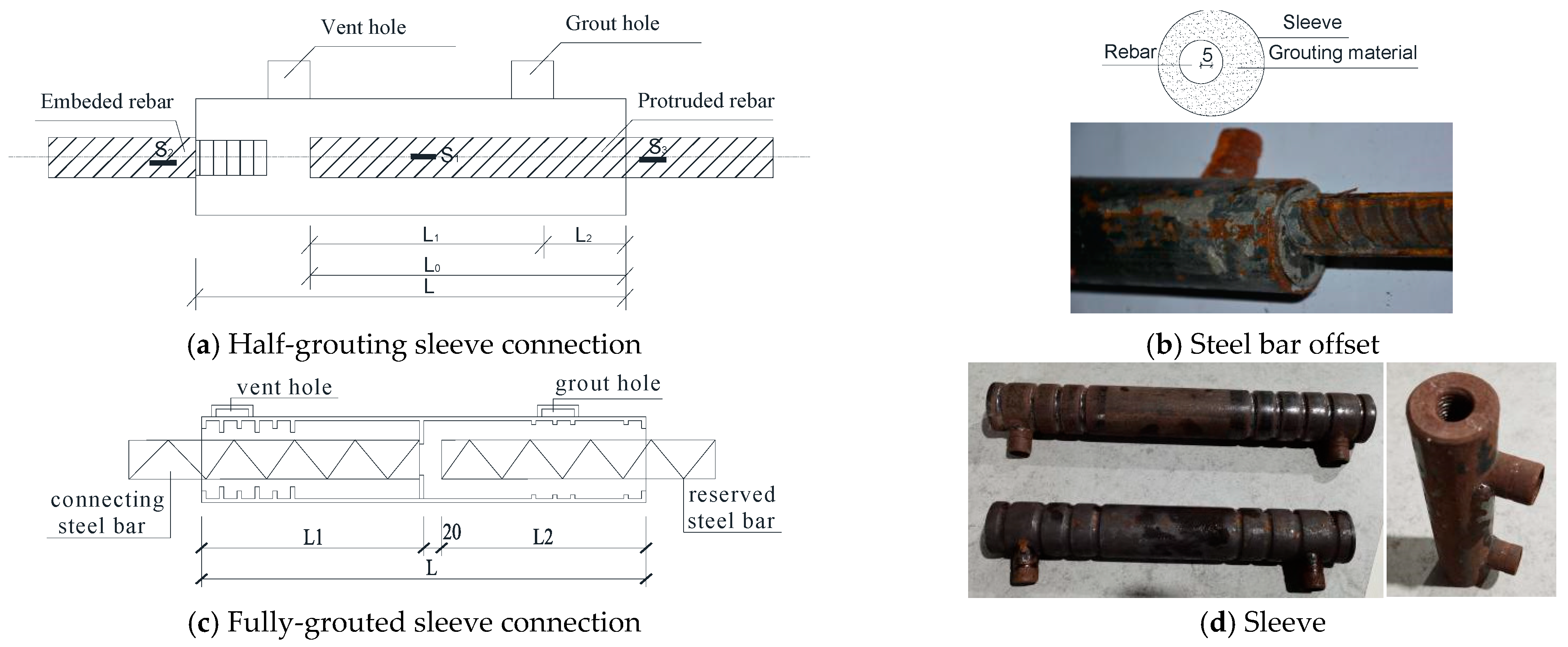
2.1. Specimen Design

In actual engineering, there may be construction positioning errors, which leads to reinforcement bias. Therefore, this test targets the semi-grouting and full-grouting sleeve connection joints of the reinforcement bias state, and the variables are the anchorage length and the diameter of the reinforcement. The schematic diagram of the specimen is shown in Figure 1.
According to the current standard Technical Regulations for Application of reinforcement sleeve grouting connection JGJ 355-2015 [22] and Technical Regulations for Mechanical Connection of reinforcement, JGJ 107-2016 [23], specimens are designed, and single-pull tests are conducted. Considering the actual construction deviation, the design specimen shown in Figure 1c is reinforcement offset, and the deviation value between the reinforcement centre and the middle line of the sleeve is 5 mm. The diameters of the selected connecting steel bars are 12 mm, 14 mm, 16 mm and 20 mm. The grouting material strength grade is C60, and the reinforcement grade is HRB400. In order to ensure a relatively accurate anchorage length, the specimen is placed vertically on the fixing frame for grouting, and the position marking line is drawn on the outside of the sleeve. The grouting is stopped when the grouting material reaches the marking line. A total of 21 semi-grouting and 12 full-grouting sleeves were carried out. A total of 11 sets of working conditions were designed according to the research purpose and significance. The test piece design details are shown in Table 1.

2.2. Material Properties

The measured compressive strength of grouting material test block (40 mm 40 mm 160 mm) is 85 MPa;The fully grouted test sleeve adopts steel sleeve, with the steel diameter of 14 mm, 16 mm and 20 mm, the sleeve type is GT14, GT16 and GT20, the length of the three models is 156 mm, 174 mm and 211 mm respectively, the insertion length of steel bar in full grouting section is 112 mm, 128 mm and 160 mm respectively; The semi-grouting joint specimens with 12 mm, 14 mm and 16 mm adopts steel sleeve, the sleeve models are GTJQ 4-12, GTJQ 4-14 and GTJQ 4-16, with a total length of 245 mm, 280 mm and 310 mm respectively, and the length of full grouting section is 102 mm, 120 mm and 135 mm respectively; The rebar used in the semi-grouting sleeve joint and full grouting joint are different batches of HRB400 rebar. Measured by the reinforcement tensile test, for the reinforcement used in semi-grouting specimens, the measured yield strength and limit strength of 14 mm reinforcement are 514.2 MPa and 706.0 MPa, respectively; the yield strength and limit strength of 16 mm reinforcement are 509.1 MPa and 688.6 MPa respectively, and the yield strength of 20 mm reinforcement are 505.1 MPa and 679.9 MPa respectively. For the reinforcement used in the full grouting specimens, the yield strength and limit strength of 12 mm diameter reinforcement are 495.1 MPa and 688.8 MPa, respectively, and the yield strength of 14 mm diameter reinforcement is 544.5 MPa and 729.0 MPa respectively; the yield strength and limit strength of 16 mm diameter reinforcement are 529.1 MPa and 708.6 MPa, respectively.

2.3. Test Device and Loading Method

The load was applied using the MTS 1000 kN Servo-HydraulicTesting System as shown in Figure 2; make the loading system in accordance with Article A.1.4 of JGJ 107-2016. According to Article 5.0.6 of the Technical Specification for Application of Reinforcement Grouting Connection (JGJ 355-2015) [22], the loading rate is ascertained to the method in the Technical Specification for Mechanical Connection of Reinforcement, see Appendix A.14 of JGJ 107-2016 [23]. It is recommended that the static loading rate is 0.05 Lc/min, Lc = 500 mm~1000 mm, and the rate range is 0.416~0.833 mm/s, so the middle value of 0.6 mm/s is taken as the loading rate. The specific loading system is as follows: first, load to 0.6 fykAs at a rate of 1 kN/s before unloading to 0, and then load to failure at a rate of 0.6 mm/s by displacement control.
The load-displacement data adopts the data output by the MTS, and the MTS instrument is calibrated before testing to ensure the accuracy and reliability of the data.

3. Experimental Results and Discussion

3.1. Analysis of Damage Mode and Stress Mechanism

There are three common forms of sleeve grouting connection failure, namely (1) the steel bar outside the joint is broken; (2) the reinforcement is pulled out from the grouting material; (3) the bond between the grouting material and the sleeve fails, which shows that the grouting material is pulled out with the whole reinforcement [14]. As shown in Figure 3, the damaged patterns of the two connection specimens in the test of this paper. In both the half-grouting and the full-grouting specimens, there is a fracture of the steel bar outside the joint and the reinforcement is pulled out.
For the half grouting specimens B14-84, B16-128, B16-96, B20-160 and B20-12 (reinforcement anchorage length greater than 6d), the full grouting sleeve joint specimens Q12-102, Q14-120 and Q16-135 (reinforcement anchorage length greater than 8.4d). The failure of the steel bar, as shown in Figure 3a, occurred due to the successful sleeve grouting connection failure mode. At the initial stage of loading, the specimen deformation is not obvious; with the increase of load, there is a slight cracking sound. When the load continues to increase, one end of the steel bar appears to have a neck shrinkage phenomenon, and the steel bar deformation is obvious, accompanied by a larger mortar cracking sound. In the late loading period, the steel bar deforms sharply and breaks. When the joint is broken, you can see that the end has more broken grouting material. It can be seen from Table 1 that the specimen strength of the tensile and failure mode is in line with the requirements of the Technical Regulations for application of reinforced sleeve grouting connection (JGJ 355-2015) [22] and the Technical Regulations for reinforced Mechanical Connecting (JGJ 107-2010) [24] (i.e., the measured tensile strength of the joint is not lower than the standard value of the ultimate tensile strength of the connected steel bar and 1.25 times the standard value of reinforced yield strength). At this time, the bonding force between the grouting material and the sleeve and the bonding force between the steel bar and the sleeve is relatively large, enough to resist the external load. Because the sleeve and the grouting material have a circumferential binding effect on the reinforcement, when the applied load exceeds the bearing capacity of the reinforcement, the reinforcement breaks outside the joint and the reinforcement will not break in the sleeve, so the bearing capacity of the joint depends on the material performance of the reinforcement itself.
Test pieces B20-81, B20-73, B20-86, Q16-58, Q16-65, and Q16-60 all suffered the reinforcement extraction failure patterns as shown in Figure 3b, the tensile strength of the joint is much less than the tensile strength of the steel bar. At the early stage of loading, the small cracking sound of the grouting material can be heard. Because the grouting material is far from the end of the sleeve, the sleeve has a great constraint effect on the grouting material, and no cracks are found in the grouting material. Continue to apply the load until the reinforcement is pulled out of the sleeve, during which no obvious deformation of the reinforcement is found. After observing the damaged specimen, it was found that there was grouting material debris between the two ribs of the steel bar and the grouting material in the sleeve was split. The reason for this damage is that the anchorage length of reinforcement is too short, the contact surface between reinforcement and grouting material is small, and the mechanical bite force is insufficient; at this time, the bearing capacity mainly depends on the bonding force between the reinforcement and the grouting material; As the external load gradually increases to exceed the bonding force between the reinforcement and the grouting material, relative slip occurs between reinforcement and grouting material, and detached from each other, then leading to bond failure. Finally, the steel bar is pulled out. At this time, the bearing capacity depends on the chemical bonding force of the grouting material and the reinforcement. It can be seen from the load-displacement relationship curves that the deformation capacity and energy consumption capacity of this damage are too small; therefore, in the construction, adequate length of steel bars shall be guaranteed to avoid the steel bars being pulled; during the construction, the grouting mouth which is not easy to leak slurry should be used and combined with the method of secondary grouting, and input at any time to detect the density.
H. Nassiraei [25] investigated reinforced connections under static load; they investigated the strength and load-displacement curves and proposed a formula to predict the strength; this provides a good reference for writing this paper. Figure 4 shows a plot of the load-displacement relationship of the specimen. It can be seen that for specimens in which the reinforcement is pulled out and the anchorage length is about the same, The load-displacement curve of the semi-grouting sleeve connection specimens such as B20-4.1d shows the elastic deformation stage, yield stage and reinforcement stage of the steel bar. However, the ultimate bearing capacity does not reach the ultimate bearing capacity value of the corresponding steel base material. However, the full grouting sleeve connection test Q16-3.6-1 only experienced the elastic deformation stage, and the reinforcement was not yielded. For the specimen that was broken outside the joint, whether for full grouting or half grouting sleeve connection, as the load increased, they all experienced the typical states of elasticity, yield, reinforcement and neck shrinkage; at this time, the bond of the grouting material and the steel bar, and the grouting material and the sleeve is strong enough, and the steel bar outside the sleeve is in a tensile state. The ultimate bearing capacity depends on the material performance of the steel bar, which increases with the increase of the diameter of the steel bar.
The energy consumption capacity reflects the size of the energy released when the specimen is destroyed. The greater the energy consumption capacity is, the less energy is released during the damage, and the less harm is, which can be expressed by the area surrounded by the load-displacement relationship curve and the horizontal axis. As can be seen from Figure 4, for both forms of specimens, the limit displacement increases as the reinforcement diameter increases and the energy consumption capacity increases. The energy consumption capacity and limit displacement of rebar extraction failure specimens are significantly lower than those of rebar fracture specimens. In addition, by comparing the two types of specimens, it can be found that when the reinforcement diameter is the same, the performance of the half-grouting sleeve is better than that of the full-grouting specimen, but the reinforcement thread of the half-grouting specimen is prone to damage, and the quality should be strictly controlled during processing.
To sum up, the project should avoid damage caused by reinforcement extraction, and the grouting quality should be controlled to ensure the corresponding reinforcement anchorage length and grouting fullness.

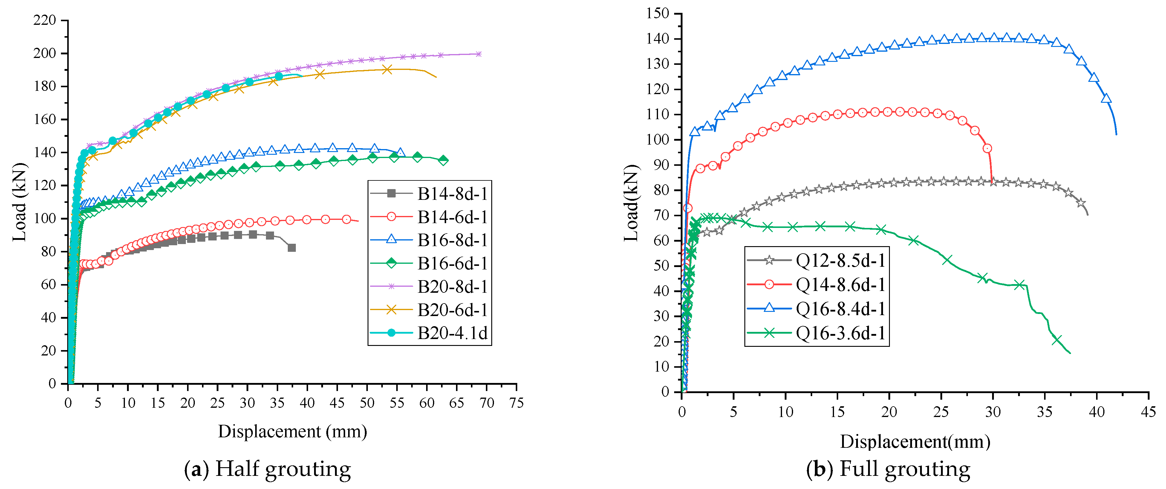
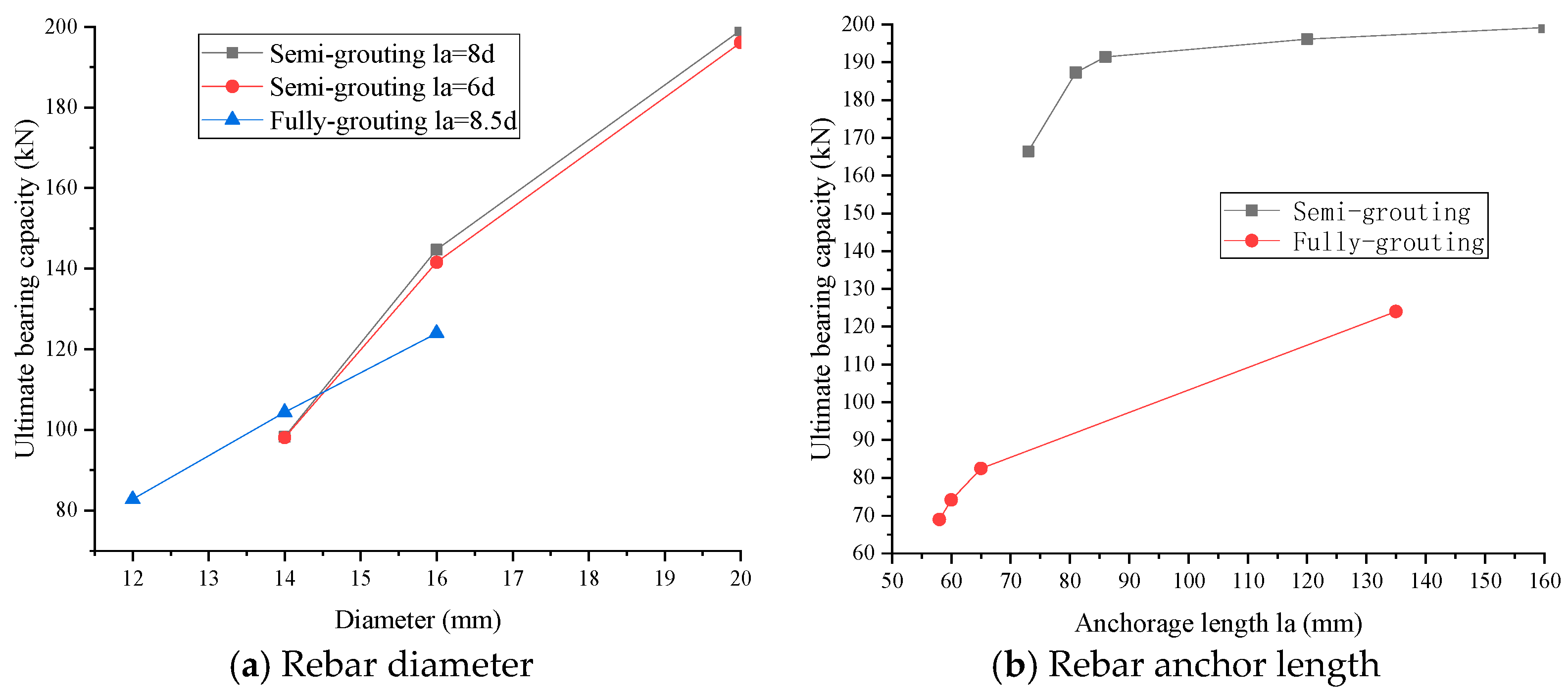
3.2. Analysis of the Influencing Factors of the Ultimate Bearing Capacity

In order to analyse the influencing factors of the ultimate bearing capacity of the joint more directly, the variation rules of the bearing capacity with the two influencing factors of steel bar diameter and steel bar anchorage length as variables are presented, respectively. As can be seen from Figure 5, when the anchorage length of the reinforcement is the same, the ultimate bearing capacity is directly proportional to the diameter of the reinforcement. The average ultimate bearing capacity of full grouting sleeve joint specimens Q12-8.5d, Q14-8.6d, and Q16-8.4d are 82.8 kN, 104.4 kN and 124 kN, respectively. When the diameter is 12 mm, the bearing capacity of 14 mm and 16 mm specimens is increased by 26.1% and 49.8%, and the anchorage length of the specimens with these three kinds of steel bar diameters is approximately 8.5d. When the anchorage length is 8d, the average ultimate bearing capacity of the semi-grouting sleeve joint specimens B14, B16, and B20 is 98.3 kN, 144.7 kN and 199.2 kN, respectively. Compared with the diameter of 14 mm, the bearing capacity of the specimens with the diameter of 16 mm and 20 mm is increased by 47.2% and 102.6%. It can be concluded that when the anchorage length is the same, the ultimate bearing capacity of the joint increases with the increase of the diameter of the steel bar.
When the reinforcement anchorage lengths are 3.7d, 4.1d, 4.3d, 6d and 8d, the ultimate bearing capacity of the semi-grouting specimen B20 is 166.4 kN, 187.3 kN, 191.4 kN, 196.1 kN and 199.2 kN, respectively. It can be seen that when the anchorage length is less than or equal to 4.3d, the ultimate bearing capacity of the semi-grouting specimen B20 is 166.4 kN, 187.3 kN, 191.1 kN and 199.2 kN, respectively. The ultimate bearing capacity increases linearly with the increase of the anchorage length; when a certain number is reached, the bearing capacity changes little with the increase of anchorage length and then tends to be stable. For specimens with full grouting sleeve connection, when the anchorage lengths are 3.6d, 3.8d, 4.1d and 8.4d, the ultimate bearing capacity of specimen Q16 are 69 kN, 74.2 kN, 82.5 kN and 124.0 kN, respectively. It can be seen that the ultimate bearing capacity increases with the increase of anchorage length. However, when the anchorage length is less than or equal to 4.1d, the ultimate bearing capacity is significantly lower than that of the steel base material, and the failure mode is the pulling-out failure of the steel bar. When the anchorage length reaches 8.4d, the ultimate bearing capacity is similar to that of the steel base material, and the fracture failure of the steel bar occurs. When the anchoring length la is 6d, the average ultimate bearing capacity of the semi-grouting sleeve connection specimens B14, B16 and B20 are 98.1 kN, 141.6 kN and 196.1 kN, respectively. Compared with the result of la = 8d, the relative deviation is 0.2%, 2.1% and 1.56%. It can be seen that when the anchoring length exceeds 6d, the average bearing capacity of the semi-grouting sleeve connection specimens is 98.1 kN, 141.6 kN, and 196.1 kN, respectively. It can be seen that when the anchoring length exceeds 6d, the bearing capacity of the semi-grout specimen basically does not change.
It can be seen that there are critical anchoring lengths, that is, effective anchoring length Le, for both semi-grouting and full-grouting specimens. When the embedded-length Le of the steel bar exceeds, the bearing capacity of the joint no longer increases with the increase of the anchoring length. The critical anchorage length is the limit of two failure modes, namely, the fracture of steel bars and the withdrawal of steel bars.

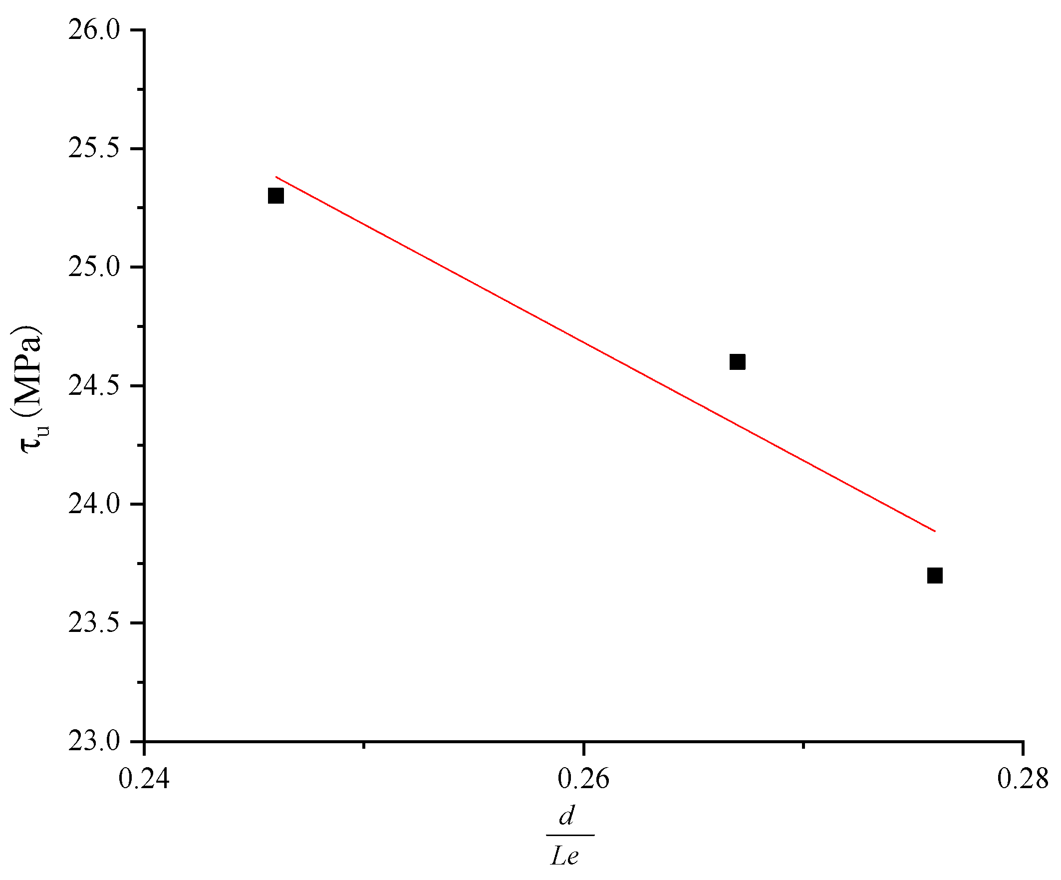
3.3. Ultimate Bond Strength Model

Based on the experimental results of this paper and the existing research data, the formula for calculating the bond strength when the bar outside the joint is broken and the bar is pulled out is proposed.
(1)
Establishment of calculation formula based on fracture failure of steel bar outside joint:
For specimens with broken rebars, the ultimate bearing capacity largely depends on the performance of the steel bar, and the following formula can be used to express the ultimate bearing capacity F u .
F u = K π d 2 f y 4 = K F 0 , F 0 = π d 2 f y k 4
According to the statistics of the existing test data, the calculated F0 are listed in Table 2. As shown in Figure 6, F0 is taken as the horizontal coordinate, and Fu is taken as the longitudinal coordinate, and the linear fitting results show that the semi-grouting parameter K is equal to 1.79 and the full-grouting parameter K is equal to 1.74. Considering the safety, the reduction factor 0.9 is introduced, and the calculated semi-grouting parameter K is equal to 1.611. The total grouting parameter K is about 1.566. Then, the corresponding coefficient K is substituted into Formula (1) to calculate the calculated value. The specific calculation results and relative deviation are shown in Table 2. By comparing the data in Table 2, it can be seen that the error between the calculated results and the test data is less than 25%, and the theoretically calculated values are all smaller than the actual test values. Therefore, it is safe to adopt the formula proposed in this paper during the design.
Therefore, the ultimate bearing capacity of the fractured joint of the steel bar outside the joint can be calculated according to the following formula:
Semi-grouting:
F u = 1.611 π d 2 f y 4 ,   τ u = f u d L e
Fully-grouting:
F u = 1.566 π d 2 f y 4 ,   τ u = F u π d L e
(2)
Establishment of calculation formula based on bond failure between reinforcement and grout.
It has been shown that the bond strength between rebar and grout is related to many factors, and the compressive strength of grout plays a very important role in the transfer of load in rebar [29]. Therefore, some current studies only consider the binding effect of grout on reinforcement and the compressive strength of reinforcement to express the shear stress between reinforcement and grout. However, from the beginning of the grouting sleeve, the interaction force generated by the steel bar and the grouting material in the sleeve decreases linearly from the outside to the inside [30]. Therefore, the effective anchorage length of the steel bar should be considered when calculating the bond strength Le.
At present, most studies believe that the bond mechanism between reinforcement and grout is similar to that between steel and concrete. Therefore, the bond strength formula of reinforcement grout can be proposed by referring to the existing bond strength formula of reinforced concrete (4). The bond strength formula of the semi-grout joint is based on the research results of this subject.
τ u = ( a + b d L e ) f m
Semi-grouting [31]:
τ u = ( 2.009 + 7.613 d L e ) f m
F u = τ u π d L e
For fully-grouting specimens, the same calculation method as for semi-grout specimens was adopted, and a similar formula for calculating shear stress was proposed. First, the calculated values of bond strength when reinforcement and grout bond failure occurred were calculated according to Equation (6) and listed in Table 3 below. Then, the ratio of reinforcement diameter to measured reinforcement anchorage length d L e was taken as the horizontal coordinate, the bond strength was taken as the longitudinal coordinate to establish a coordinate axis, and data fitting was carried out. The coefficients in Formula (4) are obtained.
The ultimate bearing capacity of fully-grouting sleeve connector specimens Q16-3.6d, Q16-4.1d and Q16-3.8d are 82.5 kN and 74.2 kN, respectively. According to Formula (3), the corresponding bond strengths are 23.7 MPa, 25.3 MPa and 24.6 MPa, respectively, with an average value of 24.5 MPa. As shown in Figure 7, linear fitting of the data was obtained a = 4.078, b = −5.401, and the formula for calculating the bond strength was obtained:
τ u = ( 4.078 - 5.401 d L e ) f m
The maximum bond strength calculated from Formula (7) is listed in Table 3, and the relative deviation from Formula (6) is within 5%. Therefore, the formula is reasonable, and Formula (7) can be used to calculate the bond strength between rebar and grout when bond failure occurs.
Where (1)–(7), τ u is the ultimate bond strength between reinforcement and grout, MPa, a and b are the coefficients, fm is the compressive strength of grout, and the measured value is 85 MPa; Le is the effective anchorage length of the steel bar, the measured value is taken when the steel bar is pulled out, mm. F u is the ultimate bearing capacity of the joint, kN; F 0 is the yield-bearing capacity of the steel bar, kN; K is the plastic development coefficient of steel bar; d is the diameter of steel bar, mm; fy is the yield strength of the steel bar, N/mm2.

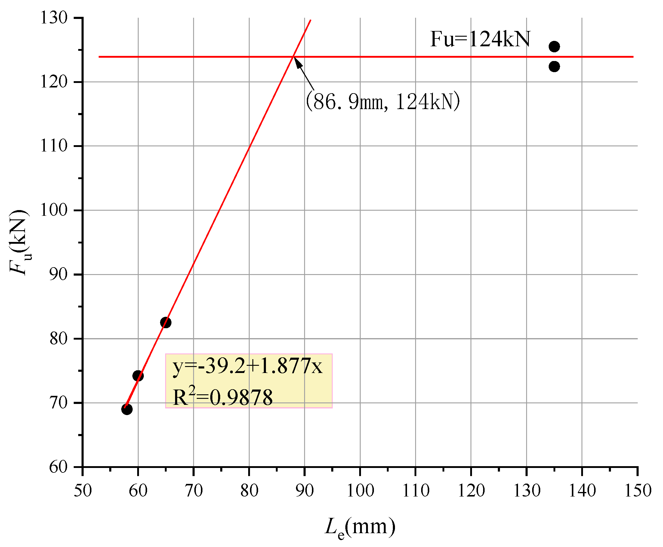
3.4. Effective Anchoring Length Model

Citing the existing research results of this subject [31], the effective anchoring length of the semi-grouting sleeve joint specimen was calculated according to Formula (8).
L e = 0.989 f y f m d
According to the analysis in Part 2 and Part 3, for the fully grouted joint specimen, when the actual anchoring length is between 4.1d and 8.4d, the joint may be damaged by steel bar pulling out or steel bar breaking, and the effective anchoring length must be between 4.1d and 8.4d. With reference to the literature [32,33], Code for Design of Concrete Structures GB50010-2010 [34] and the research results of semi-grouting in this subject, a similar calculation formula is proposed:
L e = A f y f m d
The concept and definition method of the critical anchorage length of the steel bar of the sleeve grouting joint are put forward by Q Gao, and the critical anchorage length of the steel bar under the test conditions is 5.4d [20]. With reference to this method, data fitting was performed on the full-grouting sleeve connection specimen first, and the relationship curve between the ultimate bearing capacity F u and the anchorage length Le of the steel bar when the steel bar was pulled out and damaged was obtained (Figure 8). Thus, the formula is obtained: F u = 39.2 + 1.877 L e When the steel bar is broken, the average ultimate bearing capacity of the Q16 specimen is 124.0 kN. It is calculated as the intersection of the horizontal line F u = 124.0 and the curve F u = 39.2 + 1.877 L e ; the corresponding horizontal coordinate is 86.9 mm, equivalent to 5.43d. The measured yield load of specimen Q16 is 91.3 kN, and the corresponding yield strength is calculated to be 454 MPa. By substituting these parameters into Formula (9), the coefficient A is equal to 1.017, and the formula for calculating the effective anchoring length of the joint with full grouting sleeve is obtained:
L e = 1.017 f y f m d
In order to verify the validity of the formula, the theoretical and experimental values of the bearing capacity of specimens Q12-8.5d, Q14-8.6d and Q16-8.4d were compared. According to the theory of literature [18], in the critical state, the ultimate bearing capacity calculated by pulling out and breaking limit state of the steel bar should be the same. Firstly, the effective anchoring length of the fully grouting specimen is calculated according to Formula (9), and then the calculated value of the effective anchoring length is substituted into Formula (7) to calculate the bond strength of the steel bar when it is pulled out. Finally, these values are substituted into Formula (6) to obtain the calculated value of the ultimate bearing capacity of the joint according to the fracture state theory of the steel bar. These calculated values and the measured ultimate bearing capacity are listed in Table 4. The relative deviation between the ultimate bearing capacity Fu calculated according to the method in this paper and the measured ultimate bearing capacity of the joint is less than 5%. Therefore, the calculation formula proposed in this paper can be considered reasonable.
Based on the above analysis, the ultimate bearing capacity formula, effective bond length model and maximum shear stress formula of semi-grouting and fully grouting joints were summarised as follows:
Semi-grouting:
When the steel bar is pulled out:
F u = τ u π d L e ,   τ u = ( 2.009 + 7.613 d L e ) f m
Le is the measured value;
When the steel bar breaks outside the joint:
F u = 1.611 π d 2 f y 4 ,   τ u = f u d L e ,   L e = 0.989 f y f m d
Fully-grouting:
When the steel bar is pulled out:
F u = τ u π d L e ,   τ u = ( 4.078 - 5.401 d L e ) f m
Le is the measured value;
When the steel bar breaks outside the joint:
F u = 1.566 π d 2 f y 4 ,   τ u = F u π d L e ,   L e = 1.017 f y f m d
These formulas presented here show that the bearing capacity increases with the reinforcement diameter and the effective anchorage length; the effective anchorage length increases with the reinforcement diameter and the yield strength of the reinforcement. These formulas can provide a theoretical basis for the design and construction of sleeve grouting connection joints.

4. Conclusions

On the basis of experiments and citing the existing research results, this paper analysed the failure mode and stress mechanism of the full-grouting and half-grouting sleeve grouting joint, focused on the influence of reinforcement anchorage length and reinforcement diameter on the performance of the sleeve grouting joint, and put forward the calculation formula of the effective anchorage length of reinforcement, the calculation formula of the bond strength and the ultimate bearing capacity of the joint under two failure states. The main conclusions are as follows:
  • When the reinforcement diameter is the same and the anchorage length is sufficient, the performance of the semi-grouted joint is better than that of the fully-grouted joint.
  • There is a critical anchorage length, that is, effective anchorage length, for both semi-grouted and full-grouted specimens. When the embedded length of the steel bar exceeds this limit, the bearing capacity of the joint no longer increases with the increase of the anchorage length. The critical anchorage length is the limit of two failure modes, namely, the fracture of steel bars and the withdrawal of steel bars.
  • By comparing the two types of specimens, it can be found that when the steel bar diameter is the same, the performance of the semi-grout sleeve connection specimen is better than that of the full grout specimen, but the steel thread of the semi-grout specimen is prone to damage, and the quality should be strictly controlled during processing. In order to avoid the failure of the steel bar pulling out, the grouting quality should be controlled to ensure the corresponding anchorage length of the steel bar and the filling degree of grouting.
  • Based on the mechanical principles and the test data, the reasonable value range of each parameter is determined by considering the diameter of reinforcement, anchorage length of reinforcement and grouting material performance, and the formulas for calculating ultimate bearing capacity, effective bond length model and maximum shear stress of semi-grouted and fully grouted joints are presented respectively. The formula presented in this paper is tested by tests and has also shown the bearing capacity increases with the reinforcement diameter and the effective anchorage length; the effective anchorage length increases with the reinforcement diameter and the yield strength of the reinforcement.
  • In actual engineering, appropriate calculation formulas and parameters should be selected according to the specific situation to ensure the performance and safety of the connection joint.

Author Contributions

Methodology, S.Y.; Resources, Y.X.; Data curation, L.Z.; Writing—original draft, F.Y. All authors have read and agreed to the published version of the manuscript.

Funding

This research was funded by The Enterprise Practice Training Program for Young Teachers in Higher Vocational Colleges of Jiangsu Province (2024QYSJ043), the Jiangsu Collaborative Innovation Center for Building Energy Saving and Construct Technology Young Doctor Fund Program (SJXTBZ2113), Natural Science Research Project of Jiangsu University of Education (20KJB560009), University-level scientific research project of Jiangsu Vocational Institute of Architectural Technology (JYA323-02).

Data Availability Statement

The datasets used or analysed during the current study are available from the corresponding author upon reasonable request.

Acknowledgments

The authors gratefully acknowledge the financial support from the fundings above. The experimental work described in this paper was conducted at the Key Laboratory of Building Structure Safety and Testing at Jiangsu Vocational Institute of Architectural Technology and The State Key Laboratory for Geomechanics and Deep Underground Engineering at the China University of Mining and Technology. Help from the staff and students at the laboratory during testing is greatly acknowledged.

Conflicts of Interest

Author Yonggang Xu was employed by the company China Railway Construction Bridge Engineering Bureau Group First Engineering Co., Ltd. The remaining authors declare that the research was conducted in the absence of any commercial or financial relationships that could be construed as a potential conflict of interest.

Abbreviations

sthe diameter of the rebar
Bhalf grouting connection
Qfull grouting connection
laanchorage length of the reinforcement
Pukthe standard value of ultimate load
Pykthe standard value of yield load
F u ultimate bearing capacity
F0horizontal coordinate
fyyield strength of the reinforcement
τ u bond strength
fmstrength of mortar
Leeffective anchoring length
Kplastic development coefficient of steel reinforcement
fuultimate tensile strength of the joint
Kgrouting parameter
a,bfitting coefficient of the bond strength
Afitting coefficient of the anchorage length

References

  1. Brunesi, E.; Peloso, S.; Pinho, R.; Nascimbene, R. Cyclic tensile testing of a three-way panel connection for precast wall-slab-wall structures. Struct. Concr. 2019, 20, 1307–1315. [Google Scholar] [CrossRef]
  2. Menegon, S.J.; Wilson, J.L.; Lam, N.T.K.; Gad, E.F. Experimental testing of innovative panel-to-panel connections for precast concrete building cores. Eng. Struct. 2020, 207, 110239. [Google Scholar] [CrossRef]
  3. Huang, Z.; Yang, Y.; Zhang, J.B.; Ma, S.; Cao, C. Experimental study on the tensile performance of a large-diameter UHPC grouted sleeve with thread. Eng. Struct. 2023, 294, 116707. [Google Scholar] [CrossRef]
  4. Ghayeb, H.H.; Razak, H.A.; Sulong, N.H.R. Performance of dowel beam-to-column connections for precast concrete systems under seismic loads: A review. Constr. Build. Mater. 2020, 237, 117582. [Google Scholar] [CrossRef]
  5. Cheng, J.F.; Luo, X.Y.; Cheng, Q.; Xing, M.L. Seismic performance of precast concrete walls with grouted sleeve connections using large-diameter bars. Soil Dyn. Earthq. Eng. 2023, 169, 107905. [Google Scholar] [CrossRef]
  6. Dabiri, H.; Kheyroddin, A.; Faramarzi, A. Predicting tensile strength of spliced and non-spliced steel bars using machine learning-and regression-based methods. Constr. Build. Mater. 2022, 325, 126835. [Google Scholar] [CrossRef]
  7. Shen, S.D.; Cui, Y.; Pan, P.; Gong, R.-H. Experimental study of RC prefabricated shear walls with shear keys affected by a slotted floor slab. J. Aerosp. Eng. 2019, 32, 04019013. [Google Scholar] [CrossRef]
  8. Nascimbene, R.; Bianco, L. Cyclic response of column to foundation connections of reinforced concrete precast structures. Numer. Exp. Comp. Eng. Struct. 2021, 247, 113214. [Google Scholar]
  9. Xu, J.K.; Guo, F.; Sha, J.F.; Xu, H.Y. Influence of grouting material on grouting connection performance of rebar sleeve. New Build. Mater. 2020, 47, 53–56+75. (In Chinese) [Google Scholar]
  10. Einea, A.; Yamane, T.; Tadros, M.K. Grout-filled pipe splices for precast concrete construction. PCI J. 1995, 40, 82–93. [Google Scholar] [CrossRef]
  11. Huang, Y.; Zhu, Z.G.; Naito, C.J.; Weijian, Y. Tensile behavior of half grouted sleeve connections: Experimental study and analytical modeling. Constr. Build. Mater. 2017, 152, 96–104. [Google Scholar]
  12. Wu, M.; Liu, H.T.; Du, X. Effect of tapered head sleeve structural parameters on grouting connection joints deformation. J. Mater. Civ. Eng. 2020, 32, 04020083. [Google Scholar] [CrossRef]
  13. Gao, Q.; Zhao, W.J. Experimental study on factors influencing the connection performance of grouted welded sleeves under uniaxial tensile loads. J. Build. Eng. 2021, 43, 103033. [Google Scholar] [CrossRef]
  14. Chen, J.W.; Wang, Z.W.; Liu, Z.Y.; Ju, S.L. Experimental investigation of mechanical properties of steel half-grouted sleeve splice with rebar bonding defects. J. Build. Eng. 2022, 50, 104113. [Google Scholar] [CrossRef]
  15. Xiao, J.Z.; Liu, L.L.; Li, J.X.; Zhou, X.M.; Kuang, Z.P.; Pan, Z.F. Reviewing and Analyzing of Performance of Grouted Sleeve Splice under Direct Tensile Load. Struct. Eng. 2020, 1, 1–9. (In Chinese) [Google Scholar]
  16. Alias, A.; Sapawi, F.; Kusbiantoro, A.; Zubir, M. Performance of grouted splice sleeve connector under tensile load. J. Mech. Eng. Sci. 2014, 7, 1094–1102. [Google Scholar] [CrossRef]
  17. Yu, Q.; Sun, J.Q.; Yuan, W.H. Experimental study on bond behavior between ribbed steel bars and sleeve constrained grouting material. J. Harbin Inst. Technol. 2018, 50, 98–106. (In Chinese) [Google Scholar]
  18. Yu, Q.; Xu, X.J.; You, G.S. Experimental study on bond behavior for ribbed steel bars and grout. J. Harbin Inst. Technol. 2017, 49, 91–101. (In Chinese) [Google Scholar]
  19. Qu, X.S.; Xie, Y.N.; Sun, Y.B.; Sun, G.J. Study of mechanical properties of grouting defective sleeve. Structures. 2023, 48, 1128–1140. [Google Scholar] [CrossRef]
  20. Gao, Q.; Zhao, W.J. Experimental study on performance of grouted sleeve connection with surfacing forming under uniaxial tensile load. J. Build. Struct. 2022, 43, 208–219. (In Chinese) [Google Scholar]
  21. Cao, D.; Pan, Z.F.; Zhang, Z.; Zeng, B. Experimental and numerical study on detection of sleeve grouting defect with impact-echo method. Structures 2023, 52, 632–650. [Google Scholar] [CrossRef]
  22. JGJ 355-2015; Technical Specification for Application of Reinforcement Sleeve Grouting Joints. Ministry of Housing and Urban-Rural Development: Beijing, China, 2016. (In Chinese)
  23. JGJ 107-2016; Technical Specification for Mechanical Joining of Reinforcement. Ministry of Housing and Urban-Rural Development: Beijing, China, 2016. (In Chinese)
  24. Acceptance Criteria for Mechanical Connector Systems for Steel Reinforcing Bars: AC-133; International Code Council: Whittier, CA, USA, 2010.
  25. Nassiraei, H. Probabilistic analysis of strength in retrofitted X-Joints under tensile loading and fire conditions. Buildings 2024, 14, 2105. [Google Scholar] [CrossRef]
  26. Liu, Q.Z.; Lin, Y.H.; Li, J.Z.; Yang, C.J.; Chen, J.Y.; Zhang, M.; Liu, B. Bond strength prediction model of defective grout materials in half-grouted sleeve connections under uniaxial and cyclic loadings. Constr. Build. Mater. 2022; 352, 128981. [Google Scholar]
  27. Chen, X.; Miao, Q.S.; Yang, C.T.; Ge, D.D.; Liu, Q.M.; Xie, L.L. Experimental study on tensile performance of defect detectable and repairable half grouted sleeve connection. Eng. Mech. 2020, 37, 199–207. [Google Scholar]
  28. Henin, E.; Morcous, G. Non-proprietary bar splice sleeve for precast concrete construction. Eng. Struct. 2015, 83, 154–162. [Google Scholar] [CrossRef]
  29. Rahman, A.B.A.; Yoon, L.H.; Ibrahim, I.S.; Mohamed, R.S.; Mohammad, S.; Saim, A.A. Performance of grouted splice sleeves with tapered bars under axial tension. Appl. Mech. Mater. 2015, 789–790, 1176–1180. [Google Scholar] [CrossRef]
  30. Zhou, W.X. Numerical Sulation of Tensile Behavior of Steel Sleeve Grouting Connection. South China J. Seismol. 2022, 42, 127–132. (In Chinese) [Google Scholar]
  31. Yin, F.F.; Yin, S.P.; Qin, T.H.; Wang, B.X.; Zhang, L.L.; Yang, N. Experimental study on the effect of grouting volume on the tensile performance of offset semi-grouted couplers. Constr. Build. Mater. 2022, 351, 128781. [Google Scholar] [CrossRef]
  32. Wang, Z.W.; Chen, J.W.; Ju, S.L.; Liu, Z.Y. Experimental study on the influence of loading mode and anchorage length on the connection performance of steel sleeve grouting. Ind. Archit. 2021, 51, 118–125+171. (In Chinese) [Google Scholar] [CrossRef]
  33. Zhao, J.; Yin, J.; Song, C. Liang, D.; Zhu, Y.H. Analysis of bonding properties of large diameter grouting sleeve considering grouting defects. Constr. Eng. 2021, 37, 106–112. (In Chinese) [Google Scholar] [CrossRef]
  34. GB 50010-2010; Code for Design of Concrete Structures. Ministry of Housing and Urban-Rural Development: Beijing, China, 2010. (In Chinese)
Figure 1. Schematic diagram of reinforcement grouting sleeve connection.
Buildings 14 02977 g001
Figure 2. Set up.
Figure 2. Set up.
Buildings 14 02977 g002
Figure 3. Failure mode diagram.
Buildings 14 02977 g003
Figure 4. The load-displacement relation curve.
Buildings 14 02977 g004
Figure 5. Diagram of influencing factors of ultimate bearing capacity.
Buildings 14 02977 g005
Figure 6. Fitting relation curve between test value and F0.
Buildings 14 02977 g006
Figure 7. Fitting curve of the ultimate bond strength calculation formula.
Buildings 14 02977 g007
Figure 8. Relation curve between ultimate bearing capacity and anchorage length when steel bars are pulled out.
Buildings 14 02977 g008
Table 1. Parameters of sleeve grouting connection test pieces.
Connection FormSleeve ModelSpecimen
Serial
NumberMeasured Anchorage Length/mmFy/kNFu/kNPuk;1.25 Pyk/kNDamage Mode
semi-groutingGT14B14-8d-1,2,33112 (8d)78.598.361.6; 69.3 Rebar fracture, yield
B14-6d-1,2,3384 (6d)70.498.1Rebar fracture, yield
GT16B16-8d-1,2,33128 (8d)109.6144.780.4; 90.5 Rebar fracture, yield
B16-6d-1,2,3396 (6d)109.4141.6Rebar fracture, yield
GT20B20-8d-1,2,33160 (8d)141.5199.2125.7;141.4 Rebar fracture, yield
B20-6d-1,2,33120 (6d)140.8196.1Rebar fracture, yield
B20-4.1d181 (4.1d)140.1187.3Rebar pulled out, yield
B20-3.7d173 (3.7d)137.8166.4Rebar pulled out, yield
B20-4.3d186 (4.3d)142.1191.4Rebar pulled out, yield
full groutingGTJQ4-12Q12-8.5d-1,2,33102 (8.5d)60.282.845.2; 50.9 Rebar fracture, yield
GTJQ4-14Q14-8.6d-1,23120 (8.6d)76.7104.461.6; 69.3 Rebar fracture, yield
GTJQ4-16Q16-8.4d-1,23135 (8.4d)91.312480.4; 90.5 Rebar fracture, yield
Q16-3.6d158 (3.6d)-69.0Rebar pulled out, not yield
Q16-4.1d165 (4.1d)-82.5Rebar pulled out, not yield
Q16-3.8d160 (3.8d)-74.2Rebar pulled out, not yield
Note: d in the specimen number is the diameter of the rebar, B and Q represent the half-grouting and full-grouting connection, respectively, and the subsequent numbers represent the diameter of the reinforcement, the anchorage length of the reinforcement, and the sequence of the specimen in the same group. Puk is the standard value of ultimate load; Pyk is the standard value of yield load. The results of one test in the Q14-8.6d and Q16-8.4d groups differ greatly from the other two, so the two values were discarded when calculating the mean load value.
Table 2. Values of plastic development coefficient K of rebar.
Connection ModeCited
Literature
Specimen SerialRebar Diameter/mmFu/kNF0/kNActual
Calculated Value of K
Formula (1)
F1
F 1 - F u F u
Semi-groutingThis paperB14-8d-1,2,31498.355.41.7789.2−9.21%
B14-6d-1,2,31498.155.41.7789.2−9.02%
B16-8d-1,2,316144.772.32.00116.5−19.51%
B16-6d-1,2,316141.672.31.96116.5−17.74%
B20-8d-1,2,320199.21131.76182.0−8.61%
B20-6d-1,2,320196.11131.74182.0−7.17%
Q. Liu et al. [26]C-0-4~922250.3136.81.83220.4−11.95%
X. Chen et al. [27]F-d12-01272.2840.71.7865.6−9.29%
D-d12-151270.8640.71.7465.6−7.47%
D-d12-301270.9440.71.7465.6−7.57%
D-d20-020203.271131.80182.0−10.44%
D-d20--1520198.311131.75182.0−8.20%
D-d20-3020196.131131.74182.0−7.18%
Fully-groutingThis paperQ12-8.5d-1,2,31282.840.72.0363.7−23.02%
Q14-8.6d-1,2,31495.655.41.7386.8−9.25%
Q16-8.4d-1,2,31612472.31.72113.2−8.69%
X. Qu et al. [19]C-20201861131.65177.0−4.86%
C-2525300176.61.70276.6−7.81%
Henin et al. [28]8T1625.4388.76211.021.84330.5−15.00%
8T18 389.64211.021.85330.5−15.19%
8T18 387.87211.021.84330.5−14.80%
8T18 390.09211.021.85330.5−15.29%
8T18 389.20211.021.84330.5−15.09%
8T20 389.64211.021.85330.5−15.19%
8T20 378.08211.021.79330.5−12.60%
9T2028.65463.93272.921.70427.4−7.88%
9T20 463.48272.921.70427.4−7.79%
9P20 435.46272.921.60427.4−1.85%
In the table, fyk is the standard value of the yield strength of the steel bar, which is equal to 360 MPa.
Table 3. Calculation table of bond strength.
Connection ModeSpecimen SerialLe/mmFu/kNFormula (6)Formula (7)Relative
Deviation
Fully-groutingQ16-3.6d5869.023.723.90.77%
Q16-4.1d6582.525.325.3−1.20%
Q16-3.8d6074.224.624.30.30%
Table 4. Data table of effective anchoring length formula validity verification.
Specimen Serial fy/kNFu/kNLe/mm When   the   Rebar   Is   Pulled   Out   τ u Fracture State of Steel Bar FuRelative Deviation of Bearing
Capacity
Q12-8.5d532.382.878.829.885.83.57%
Q14-8.6d498.4104.483.529.2107.32.81%
Q16-8.4d454.012489.628.4124.10.11%
Disclaimer/Publisher’s Note: The statements, opinions and data contained in all publications are solely those of the individual author(s) and contributor(s) and not of MDPI and/or the editor(s). MDPI and/or the editor(s) disclaim responsibility for any injury to people or property resulting from any ideas, methods, instructions or products referred to in the content.

