Article

A Study on Improving the Shape Error of the Lower Mold of Free-Form Concrete Panels Using Magnetic Force

1
Department of Architectural Engineering, Hanbat National University, Daejeon 34158, Republic of Korea
2
Division of Architectural Engineering, Hannam University, Daejeon 34432, Republic of Korea
*
Author to whom correspondence should be addressed.
Buildings 2024, 14(9), 2979; https://doi.org/10.3390/buildings14092979
Submission received: 6 August 2024 / Revised: 13 September 2024 / Accepted: 17 September 2024 / Published: 20 September 2024
(This article belongs to the Section Building Materials, and Repair & Renovation)

Abstract

:
FCPs (free-form concrete panels) can be made using reusable and easily customizable silicone molds tailored to the unique shape of each panel. CNC (Computer Numerical Control)-type rods move vertically to press the silicone plate and shape the lower curved surface. Silicone caps are attached to the ends of the rods to facilitate the formation of smooth curves. However, there is currently no fixing method for the silicone caps and the silicone plate, which makes them vulnerable to the lateral pressure exerted during concrete pouring. Therefore, the current study used magnetic force to improve the lower shape of free-form molds. To this end, a neodymium silicone cap was designed by adding a neodymium magnet to the upper surface of the silicone cap. Moreover, two types of silicone plates were developed for fixing: one type is IS-LSM (Iron Sheet–Silicone Mold), which includes an iron sheet, while the other type is IP-LSM (Iron Powder–Silicone Mold), which is made by mixing iron powder. To verify these two techniques, FCP manufacturing experiments were conducted. The experimental results indicated that IS-LSM had a broader error range than existing techniques, thus rendering it unusable, while IP-LSM yielded significant values. Consequently, a t-test was conducted to validate the data for IP-LSM at 30%, 50%, and 70%, and it was confirmed that the difference in error data was significant at a 95% confidence level. Future research in this area should investigate the addition of iron powder to the silicone plate and a side fixing method for the silicone mold. Such research would help advance the production technology of free-form concrete panels.

1. Introduction

The exteriors of free-form buildings are made using free-form panels comprising various curved surfaces. These panels can be easily shaped according to manufacturing needs and applied to free-form buildings [1]. Such panels are custom-made according to the desired shape of the curved surfaces. Free-form panels are primarily made from materials such as aluminum and metal, but these materials have high processing costs. Among these, concrete is used to manufacture free-form panels due to its good flowability, practicality in realizing geometric free-form shapes, and excellent compressive and flexural strength [2]. Because of these characteristics, there have been many studies examining FCPs (free-form concrete panels) [3,4].
Custom-made free-form molds play an essential role in manufacturing FCPs. This task requires precision, and during the design process, software such as CAD, BIM, and Catia is utilized [5,6,7]. In the manufacturing process, CNC (Computer Numerical Control) equipment or 3D printers (three-dimensional printers) are used for machining and assembly [8,9]. Various digital technologies are also applied in free-form architecture, including 3D scanners that are used to verify the precision of fabricated molds [10]. However, these digital methods involve high costs, leading to the current practice wherein wood is manually processed to manufacture free-form molds. However, this method has issues, such as decreased precision and quality, as well as the production of defective panels. Further, the aforementioned molds cannot be reused after their initial use, resulting in construction waste, increased construction costs, and environmental destruction [11,12]. Therefore, reusable and precise silicone free-form molds are being utilized to address these limitations [1].
The silicone free-form mold consists of a lower mold and a side mold. As shown in Figure 1, the lower mold is composed of multiple rods that are arranged in a specific pattern, which are controlled by CNC to move up and down. On top of the rods, there is a silicone plate that forms the upper surface of the FCP. When the free-form design shape is input, the rods rise, deforming the silicone plate into the free-form shape. At this time, silicone caps are attached to the ends of the rods, which can distribute the load of the concrete applied to the silicone plate, thereby allowing for the formation of smooth curves.
Despite these advantages, the silicone mold is only fixed by the frictional force generated from the same material as the rod. This fixing method leads to deflection when pouring concrete into the mold, determined by the curved shape, which results in shape errors. Although free-form concrete panels were produced using existing silicone molds, errors caused by concrete load and lateral pressure have been identified as limitations [13]. Therefore, this study aims to utilize magnetic force as a new fixing method to ensure the precision of the lower shape of the silicone mold. To employ magnetic force, the study will analyze each component of the silicone mold and verify the performance of the new fixing method.
The research in this study will be conducted in the sequence depicted in Figure 2. First, the current study will analyze previous works on the fixing method using magnetic force, which is intended to be utilized in this study. Studies related to the manufacture of FCPs using silicone will also be examined. By analyzing previous studies, the requirements for improving the silicone cap and silicone plate, which are components of the lower mold, can be derived. Based on the derived requirements, a Neodymium silicone cap that improves upon the limitations of the existing silicone cap will be designed and manufactured. For the silicone plate, a structure that can be fixed by a Neodymium magnet inserted into a silicone cap and magnetic force will be developed. An Iron Sheet–Lower Silicone Mold (IS-LSM) with an inserted iron sheet and an Iron Powder–Lower Silicone Mold (IP-LSM) with iron powder added to silicone will be manufactured, and performance experiments will be conducted for each silicone plate. FCPs will then be manufactured using two silicone plates with the Neodymium silicone cap to verify their performance. Finally, the study will be conducted to select the optimal silicone plate by comparing and analyzing the shape errors of the manufactured FCPs to ultimately establish an operating technology for free-form lower molds.

2. Literature Review

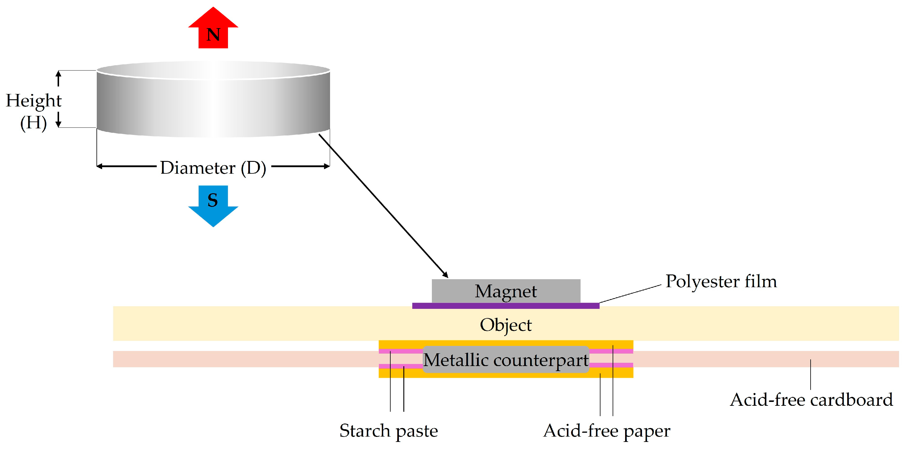
2.1. Analysis of Previous Studies on Fixing Methods Using Magnetic Force

In this study, magnetic force is intended to be used to reduce shape errors occurring in the silicone cap and silicone plate of the silicone lower mold. To utilize magnetic force, Neodymium magnets will be used. Neodymium magnets, which were initially developed in 1982 by General Motors and Sumitomo Special Metals, are permanent magnets that are five to seven times stronger than ferrite magnets, and they are typically used in hard disk drives and magnetic fixing devices [14]. The strength of a Neodymium magnet’s magnetic field varies depending on the size of the magnet [15]. Neodymium magnets are mainly used as fixing devices. A mounting system such as that shown in Figure 3 uses magnets and metallic counterparts for fixing. To utilize this type of fixing method, it is crucial to select the appropriate strength (size and thickness) and quantity of Neodymium magnets [16,17]. Therefore, the present study will conduct experiments to determine the appropriate size and thickness of Neodymium magnets based on their location and use.
The construction industry is also utilizing magnets. By applying a magnetic shuttering system to steel molds used for producing precast concrete, productivity and flexibility in the assembly process of the formwork have been enhanced. This system facilitates the assembly and disassembly of molds, increasing work efficiency and saving time in the production process. As a result, it enables faster and more effective precast concrete production [18].

2.2. Analysis of Previous Studies on the Manufacture of Free-Form Panels Using Silicone

There have been various previous studies examining the use of silicone in free-form molds. Silicone is recyclable and facilitates the formation of curved surfaces, which has led to its widespread use in free-form molds. It has excellent properties, such as heat resistance, chemical stability, electrical insulation, abrasion resistance, and weatherability [19,20]. Unlike single-use processed molds, silicone molds can be reshaped and reused for different free-form molds after demolding [21]. To manufacture silicone free-form molds, a silicone side mold was first placed on top of a wooden lower mold to realize FCPs. The manufactured panels had uniform thickness and seamless surfaces, thus verifying the usability of silicone molds [22].
Kim (2021) researched a technology that involved producing FCPs using a multi-point press CNC machine. This method deforms a silicone plate with the movement of rods operated by CNC technology underneath to ultimately manufacture FCPs. The panels manufactured with this technology had an average thickness error rate within 3% at a 95% confidence level [13]. However, slight errors occurred due to the mechanical play of the rods and the elasticity of the silicone, thus highlighting the need to improve the fixing method of the CNC equipment and the silicone plate.

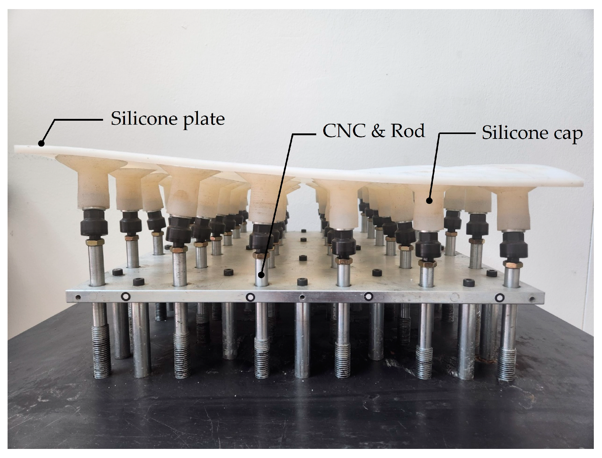
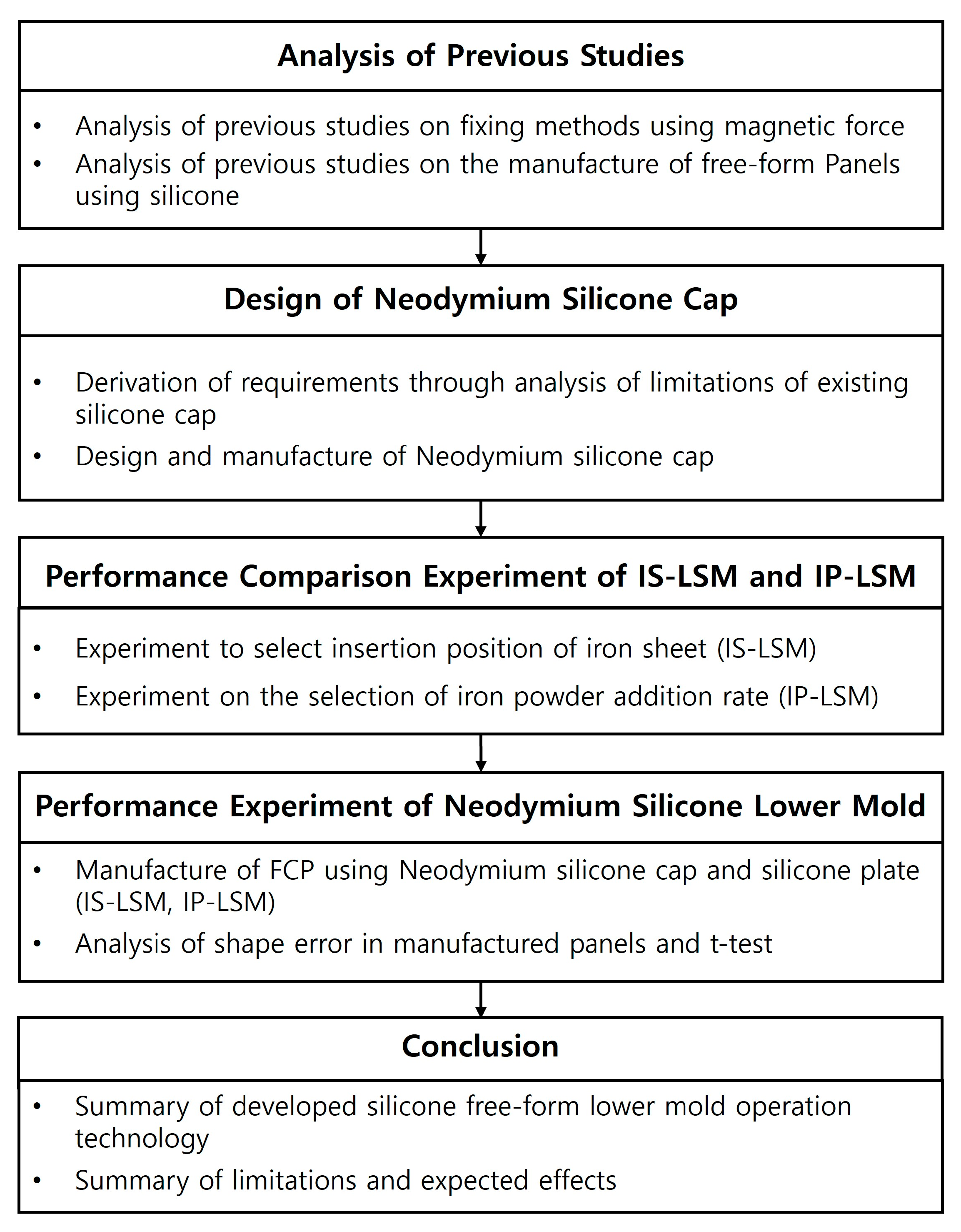
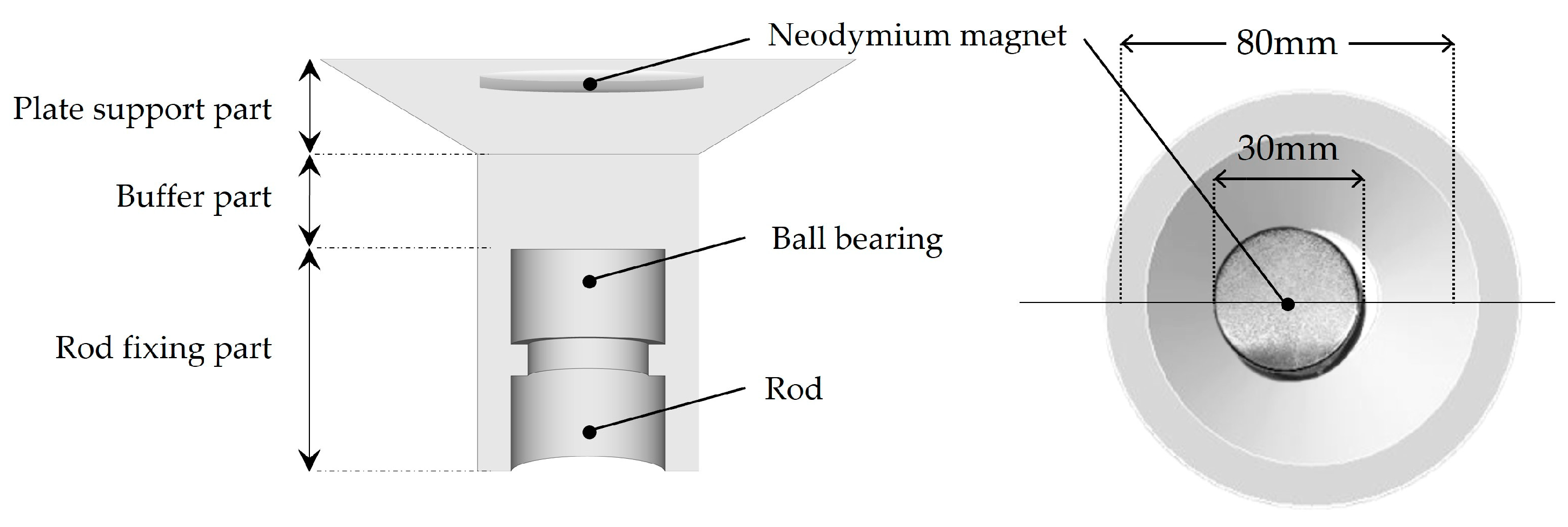
3. Design of Neodymium Silicone Cap

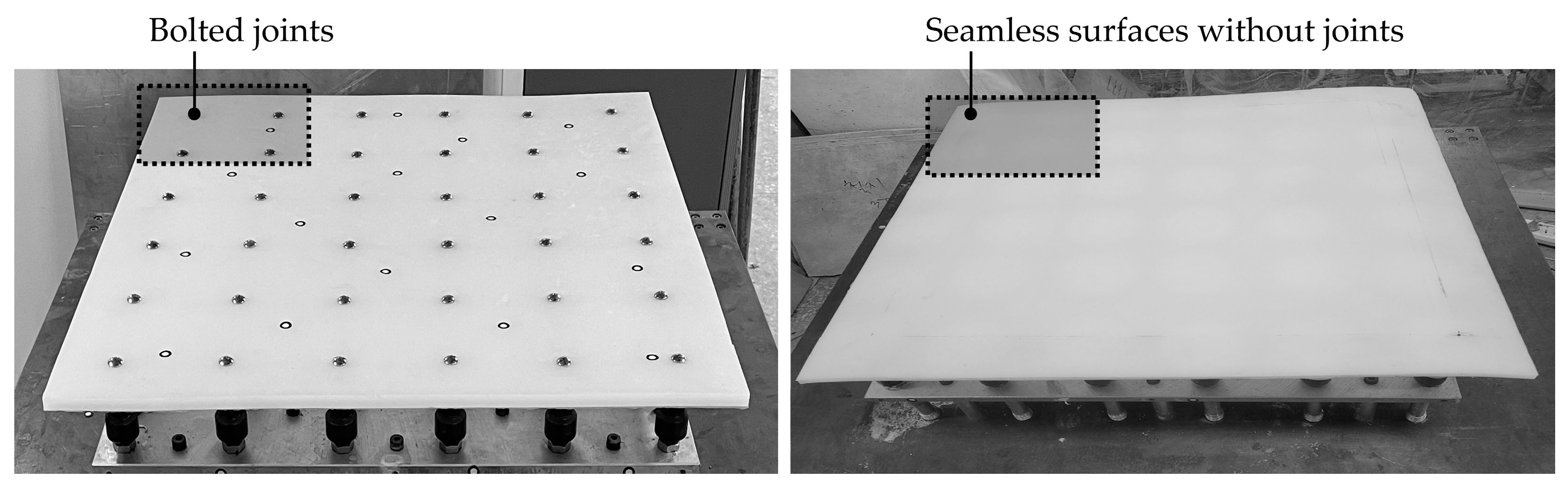
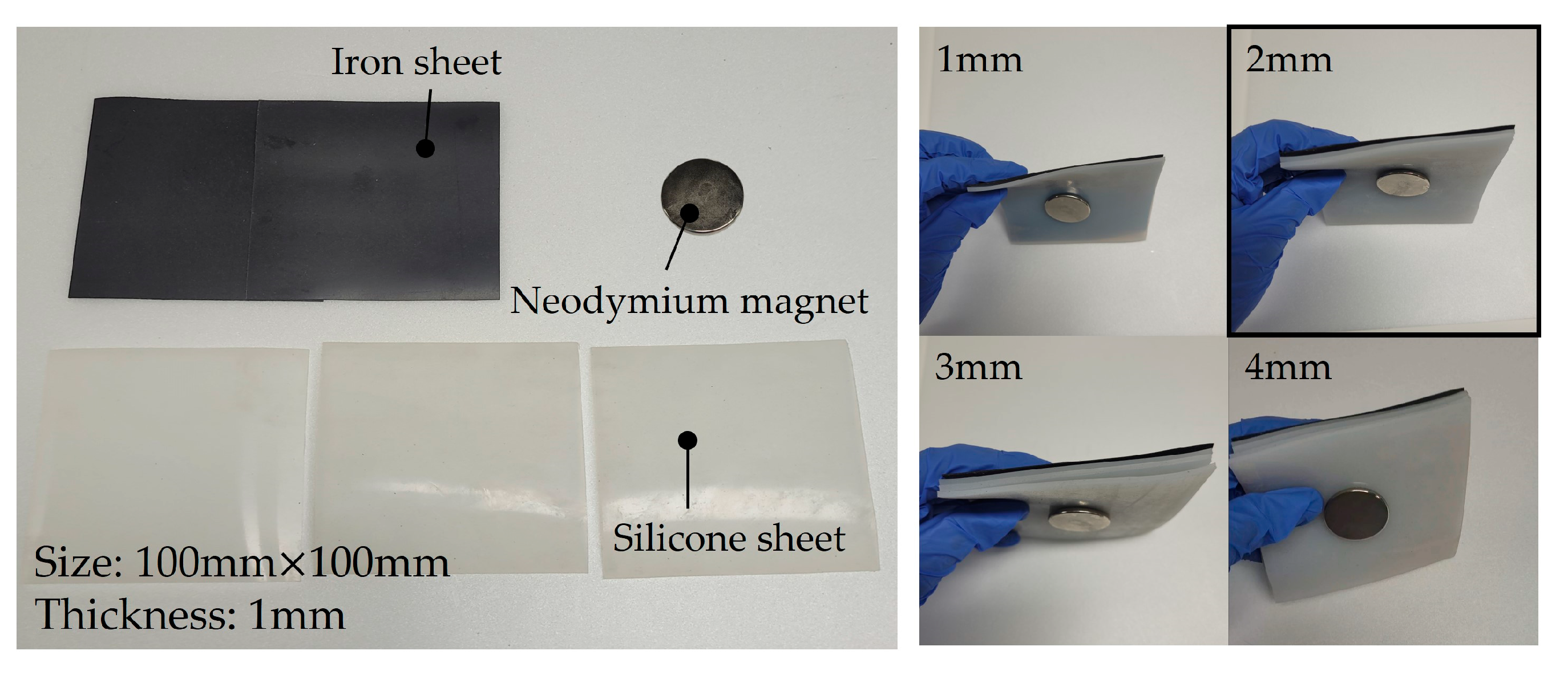
3.1. Analysis of Limitations of Existing Methods

This section focuses on existing research involving the manufacturing of FCPs using the aforementioned CNC equipment and silicone plate. In a particularly relevant study, Jeong (2020) proposed a fixed-type multi-point CNC. This method involves fixing the rods and silicone plate with bolts to realize curved surfaces. However, since the two elements are vertically connected, the silicone plate becomes distorted with the ascent of the rods, which leads to a limitation in that seamless curved surfaces are not achieved [23]. To address this issue, Yun (2022) developed a detachable silicone cap at the ends of the rods to achieve seamless curved surfaces. However, shape errors occurred due to changes in the rotation angle of the rods and the position of the bearing in the silicone cap [24]. These two devices are shown in Figure 4.
This study aims to analyze and improve upon the limitations of the detachable silicone cap proposed by Yun (2022). The existing silicone cap is attached to the end of the CNC rod to realize free-form curved surfaces. The rod has ball bearings installed, which facilitate rotation according to the curved surface and enhance the support capability of the silicone cap. Additionally, the detachable feature makes mold assembly and disassembly easy, and the silicone cap is fixed by friction due to being made of the same material as the silicone plate, which simplifies the process without requiring additional coupling methods [24,25]. However, the existing silicone cap has limitations that reduce shape precision.
First, the silicone cap fails to reach the appropriate position when realizing free-form curved surfaces. This is because the CNC rod to which the silicone cap is attached has a ball-bearing structure. The ball-bearing structure allows for free rotation, and it enables the rod to easily support free-form surfaces. However, since the ball bearing is not fixed, it cannot provide vertical support during the coupling process of the silicone cap and silicone plate. In cases where the radius of curvature of the surface is large, it is not possible to achieve complete adhesion. Second, deflection of the silicone plate occurs due to the spacing of the arranged silicone caps. When concrete is poured on the silicone plate with a free-form curved surface, the upper area of the silicone cap expands due to the concrete load, and it can resist the concrete load. However, the load that is generated by the spacing between the silicone caps cannot be supported, causing deflection in the silicone plate. This leads to errors in the FCP. Therefore, it is necessary to design a new fixing method between the silicone cap and the silicone plate.

3.2. Neodymium Silicone Cap Design

To prevent the deflection of the existing silicone cap and silicone plate analyzed in Section 3.1, a new fixing method is designed. As shown in Figure 5, the Neodymium silicone cap consists of a plate support part, a buffer part, and a rod fixing part. The plate support part combines with the lower silicone plate proposed in this study and has a magnetic coupling structure. The buffer part is composed solely of silicone material, which allows it to resist concrete loads and maintain its shape. The rod fixing part connects with the rod and has a structure that allows rotation through ball bearings.
At this point, it is necessary to determine the appropriate insertion depth of the Neodymium magnet; if it is too close to the silicone plate, deformation may occur. In this study, a basic experiment was conducted, as shown in Figure 6. By adding a 1 mm silicone sheet between the iron sheet and the magnet, the adhesion force of the magnetic field was confirmed as the distance increased. Based on the obtained results, a suitable distance of 2 mm was selected.

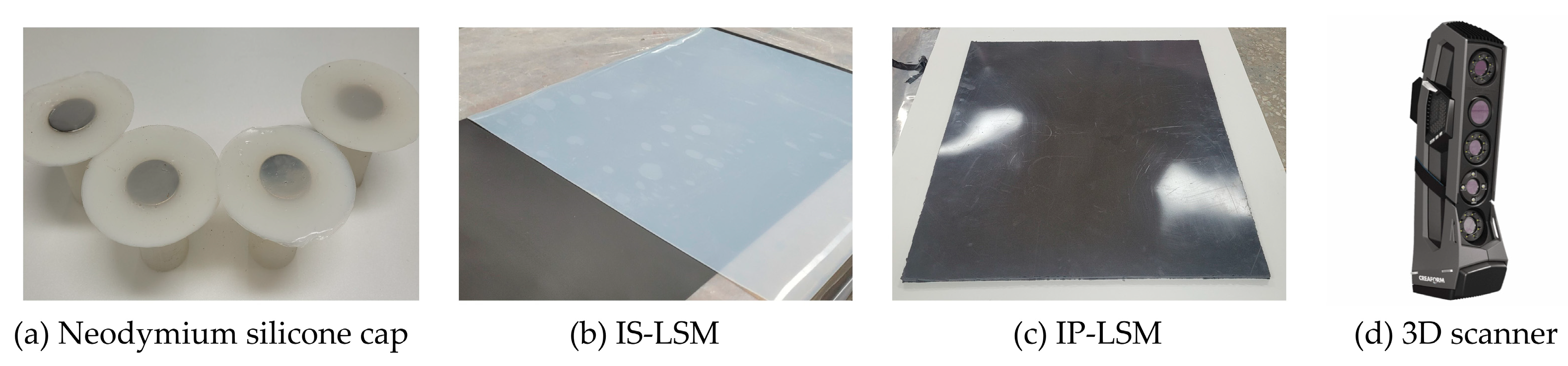
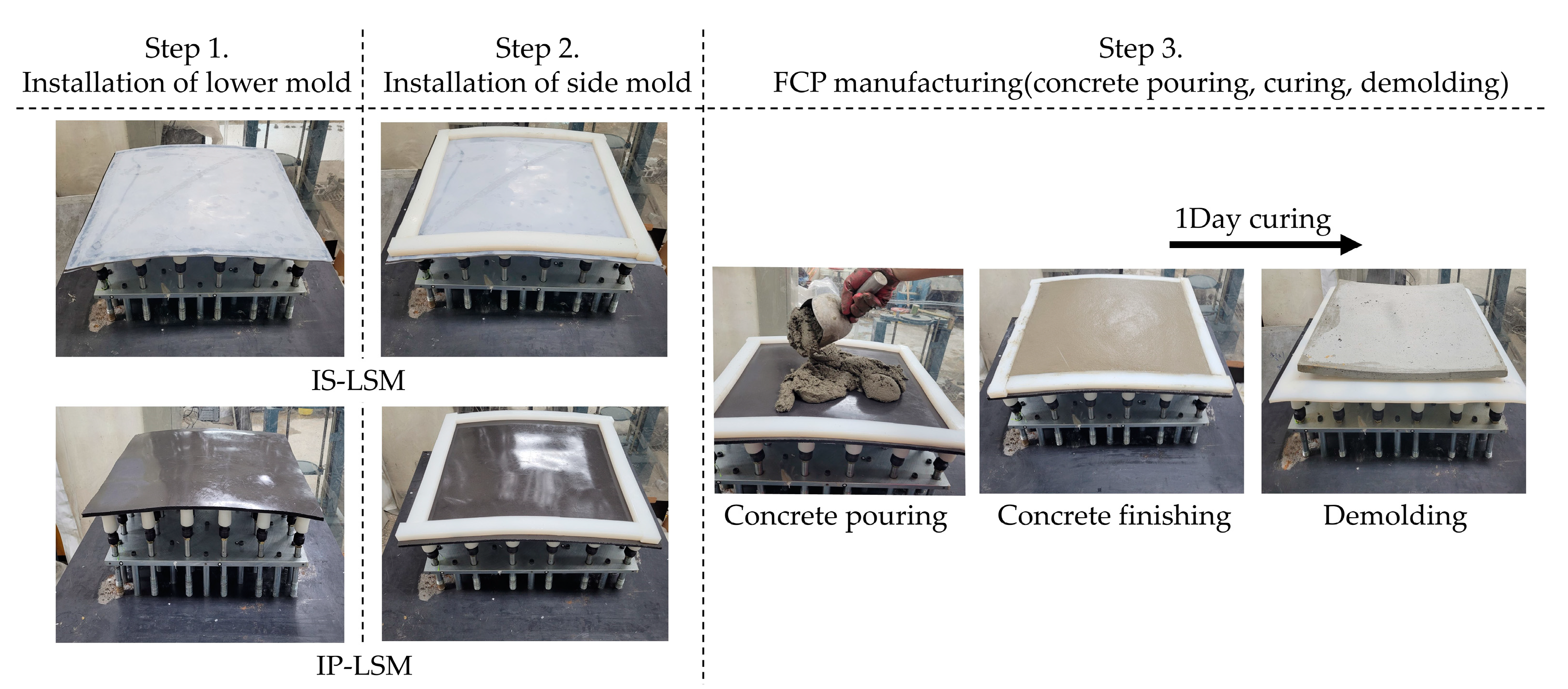
4. Manufacturing and Performance Comparison Experiment of IS-LSM and IP-LSM

Section 4 focuses on the fabrication and performance verification of a silicone plate that can be combined with the (a) Neodymium silicone cap developed in Section 3. The silicone plates presented in this study include (b) IS-LSM (Iron Sheet–Lower Side Mold), which incorporates an iron sheet into the existing silicone plate without magnetic force, and (c) IP-LSM (Iron Powder–Lower Side Mold), which involves mixing iron powder into the silicone plate. The objective is to develop these two types of plates and use a (d) 3D scanner to select a plate with suitable performance for free-form concrete panels. Figure 7 shows the equipment used in the performance comparison experiments.

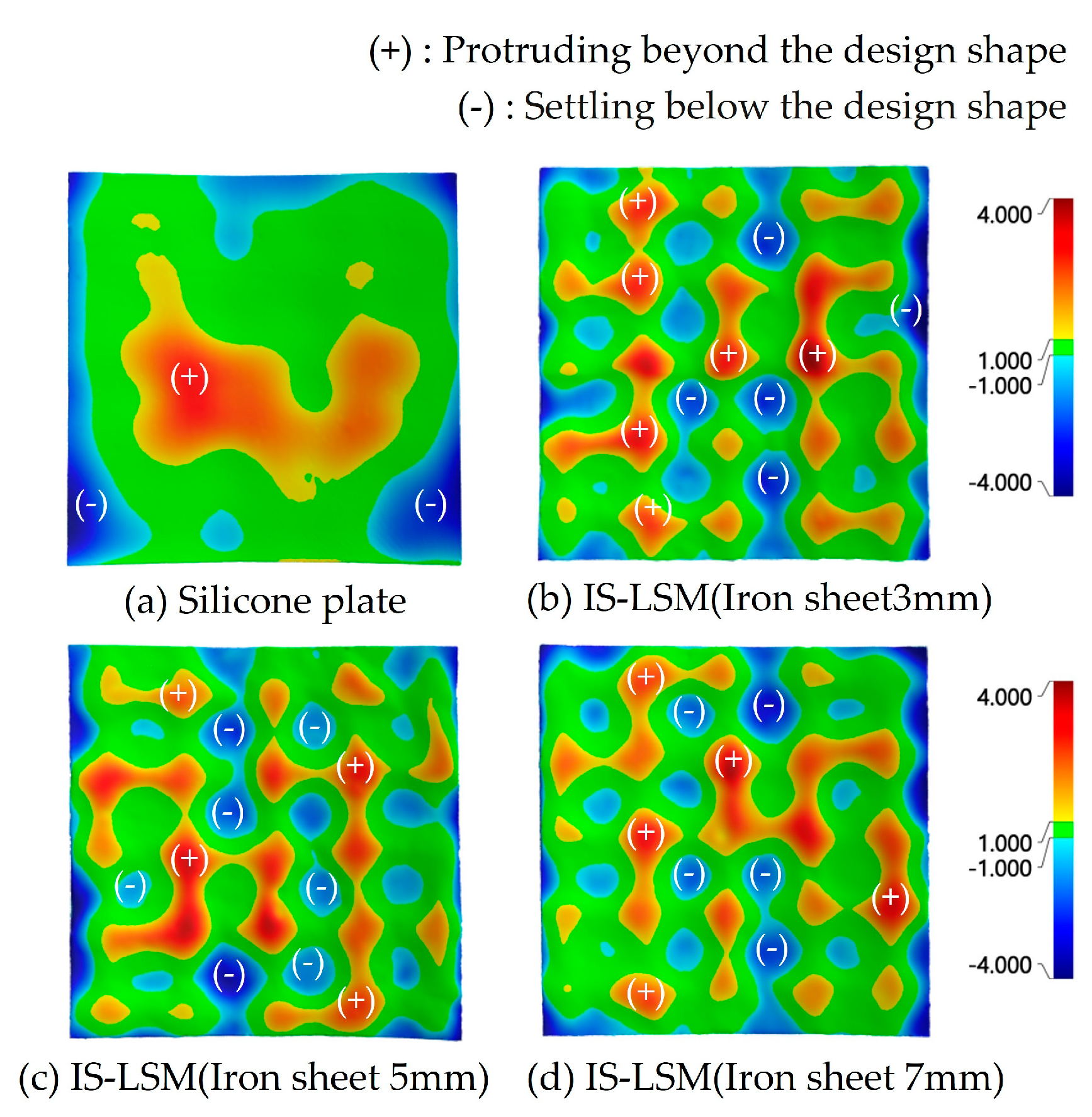
4.1. Performance Experiment for Manufacturing IS-LSM

The iron sheet used in IS-LSM is bonded in the middle of the existing silicone plate without magnetic force. The iron sheet must exhibit magnetic force to bond with the Neodymium silicone cap. To verify this, the thickness of IS-LSM is classified into 3, 5, and 7 mm, and then attached to the Neodymium silicone cap to implement a free-form shape. The error caused by the distance between the free-form shaped IS-LSM and the Neodymium silicone cap indicates the strength of the magnetic force. When realizing a free-form shape, the absence of a fixing method causes the existing silicone plate without magnetic force to generate errors in the baseline value used. The specifications of the IS-LSM to be tested are 600 × 600 mm with a thickness of 10 mm, as shown in Figure 8a. The free-form shape is realized using the lower CNC, and the curvature value is realized as a free-form shape with a curvature of 25 mm by raising the rods from X1 to X6, as shown in Figure 8b.
This study aims to analyze the shape errors of the silicone plates and IS-LSM with thicknesses of 3 mm, 5 mm, and 7 mm in free-form shapes using a 3D scanner. The specifications of the 3D scanner (Go! Scan Spark) used are shown in Table 1.
The data acquired from the 3D scanner are analyzed using the quality inspection software (VXInspect), and the error analysis range is limited to the areas affected by the Neodymium silicone cap, while the edges of the IS-LSM are treated as outliers and excluded. In the analyzed values, negative values indicate areas that were not fixed or subsided due to magnetism. Meanwhile, positive values indicate areas that protruded beyond the designed shape due to the elasticity of the silicone or the influence of the silicone cap during the free-form shape implementation process. This is shown in Figure 9.
The existing silicone plate without magnetic force has an error range of 6.251 mm, with a minimum of −2.788 mm and a maximum of 3.463 mm. The 3 mm IS-LSM has a minimum of −2.497 mm, a maximum of 3.195 mm, and an error range of 5.592 mm. The 5 mm IS-LSM has a minimum of −1.792 mm, a maximum of 3.251 mm, and an error range of 5.007 mm. The 7 mm IS-LSM has a minimum of −2.573 mm, a maximum of 3.148 mm, and an error range of 5.991 mm. These IP-LSM free-form shape error experiment data values are listed in Table 2.

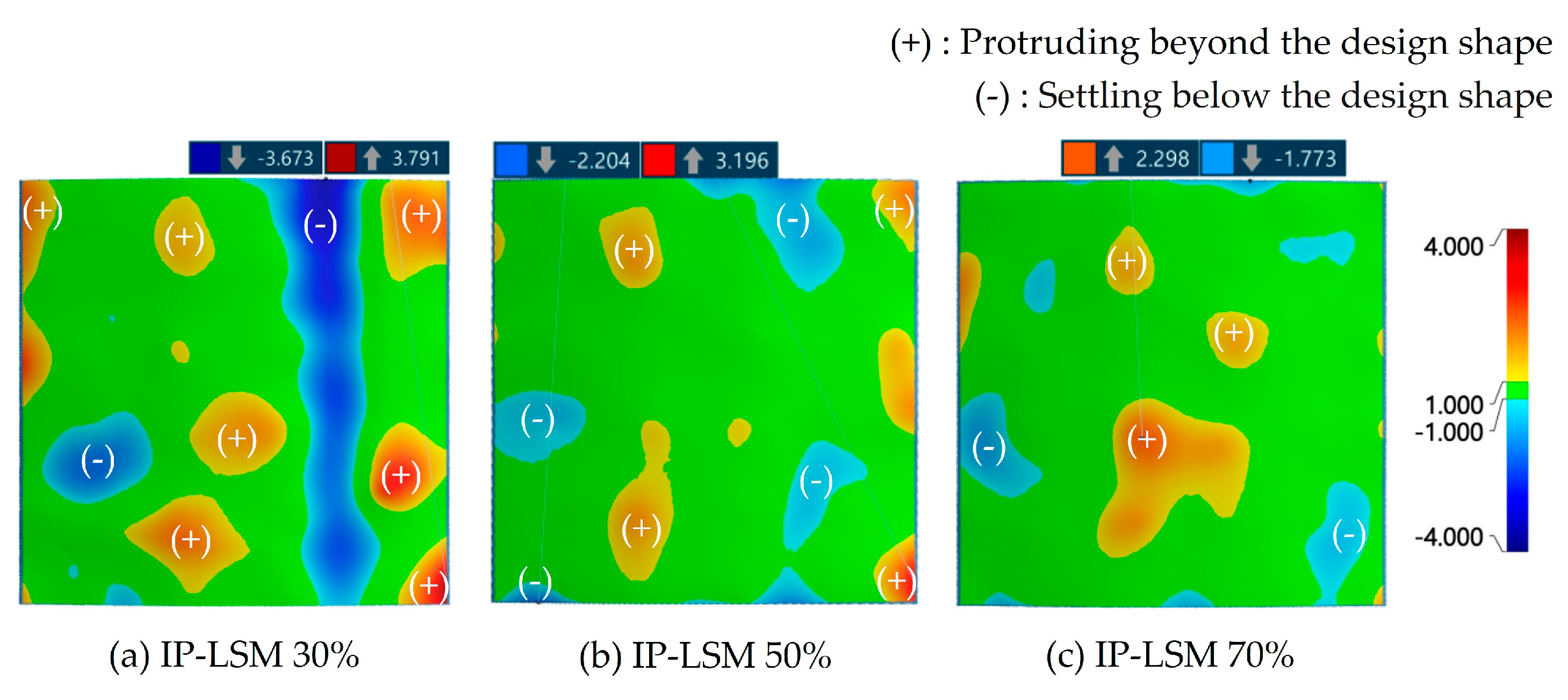
4.2. Performance Test for IP-LSM Fabrication

IP-LSM is an integrated silicone mold with added iron powder, unlike IS-LSM, which is fabricated by joining. The iron powder retains its metallic properties during the mixing process with liquid silicone. This allows for fixing with the Neodymium silicone cap and increases the rigidity of the silicone plate. However, as the addition rate increases, flexibility decreases, so it is necessary to conduct an experiment to determine the optimal iron powder addition rate. Therefore, in this study, IP-LSM specimens are manufactured by adding iron powder to molds realized with a 3D printer. Subsequently, errors will be analyzed after realizing a free-form shape. When mixed with silicone, an iron powder addition rate below 30% resulted in insufficient magnetic strength. Meanwhile, an addition rate exceeding 70% did not exhibit the desired silicone properties. Thus, this study aims to determine the optimal addition rate by manufacturing specimens with iron powder addition rates of 30%, 50%, and 70%. Errors that occurred when realizing the same free-form shape as IS-LSM were analyzed as shown in Figure 10.
For an addition rate of 30%, the minimum error was −3.673 mm, the maximum error was 3.791 mm, and the error range was measured to be 7.464 mm. For an addition rate of 50%, the minimum error was −2.204 mm, the maximum error was 3.196 mm, and the error range was measured to be 5.400 mm. For an addition rate of 70%, the minimum error was −1.773 mm, the maximum error was 2.298 mm, and the error range was measured to be 4.071 mm. Compared to the error range of the original silicone plate, the 30% addition rate showed an increase of 19.40%, while the 50% and 70% addition rates showed respective decreases of 13.61% and 34.87%. These results are collected in Table 3.

4.3. Experiment on the Manufacturing of Free-Form Concrete Panels

The technology presented in this study involves the operation of a silicone plate fixed with a Neodymium silicone cap. To select the optimal silicone plate between the IS-LSM and IP-LSM developed in Section 4.1 and Section 4.2, an FCP fabrication experiment was conducted, as depicted in Figure 11. The specifications of the FCP were 500 × 500 × 20 mm, while the rods of the CNC machine were raised to implement a free-form lower shape. After attaching the Neodymium silicone cap to the raised rods, IS-LSM and IP-LSM were installed. Side silicone molds were then installed, and concrete was poured. After curing for one day, the forms were removed, and the shapes of each FCP were finally analyzed.
The mixing ratio used was planned as shown in Table 4 based on prior research on the production of free-form concrete panels. This study aims to verify the performance of the magnetic fixing method in resisting concrete loads. Therefore, the created shapes will be assessed by checking geometric errors through 3D scanning [26].
The scanned shape of the FCP manufactured with IS-LSM is shown in Figure 12, and it can be seen that errors occurred in most parts. Existing technology allows for an error range of 3% of the design shape based on the wall structure [1]. However, the error of IS-LSM exceeded the existing error range. This is because, although the parts combined with the Neodymium silicone cap could resist the concrete load, the parts that were not combined could not support the concrete. As a result, there were partial discrepancies in the shape of the FCP, ultimately leading to the production of defective panels.
Table 5 shows the shape error values of the FCPs manufactured using IS-LSM. Overall, the error range increased compared to the existing values, and numerous errors occurred, thus failing to verify the performance.
The scanned shape of the FCPs manufactured with IP-LSM is shown in Figure 13. A visual inspection clearly suggests an improvement over IS-LSM with reduced errors even outside areas supported by the Neodymium silicone cap.
Table 6 shows the shape error values of the FCP using IP-LSM. This method improves central deflection compared to existing methods. However, there is significant data dispersion at iron powder addition rates of 50% and 70%. Therefore, a t-test will be conducted to verify the statistical significance of the shape error data obtained by dividing the sections of IP-LSM [20].
To conduct the t-test, groups were classified based on error data from existing technology and data using IP-LSM. To ensure the reliability of data collection, the FCP was divided into 16 sections, and 40 data points were randomly collected from each section. The collected data were analyzed using the statistical analysis program (SPSS). Table 7 presents the descriptive statistics for the 640 error measurements that were extracted from each group.
Table 8 lists the results of the t-test. The t-value for IP-LSM 50% is −10.477 with a p-value of 0.00, while the t-value for IP-LSM 70% is −12.952 with a p-value of 0.00. Both test results reject the null hypothesis of the two-tailed test at the 95% confidence level.

5. Conclusions

The existing silicone mold used in this process leads to errors due to the lack of a fixing method between the rod that realizes the lower shape and the silicone plate. In this study, a new lower shape implementation technology was proposed by providing both the silicone cap attached to the rod and the silicone plate with magnetic properties to address these errors.
The Neodymium silicone cap added a magnet to the upper surface of the existing silicone cap, and an experiment was conducted to select the insertion depth of the magnet. A 1 mm silicone sheet was added between the iron sheet and the magnet, with an insertion depth of 2 mm determined to be the most appropriate.
Accordingly, IS-LSM with an iron sheet inserted and IP-LSM with iron powder added were manufactured as silicone plates that can be combined. For IS-LSM, the iron sheet thickness is the same at 1 mm, while the silicone thickness was varied to manufacture IS-LSM at 3 mm, 5 mm, and 7 mm. To verify this, a unidirectional free-form shape with a central curvature of 25 mm was realized using the shape value of the existing silicone plate without magnetic force as a reference. As a result, the error range was reduced from the existing value of 6.251 mm to 5.592 mm, 5.007 mm, and 5.991 mm. IP-LSM was manufactured with iron powder addition rates of 30%, 50%, and 70%. The results of the free-form shape implementation experiment of IP-LSM confirmed improvements over the existing error range of 6.251 mm. IP-LSM 30% measured at 7.464 mm, 50% at 5.4 mm, and 70% at 4.071 mm.
An experiment was conducted to manufacture FCPs to confirm the performance of the two types of molds. The specifications of the FCP are 500 mm × 500 mm × 20 mm, and the errors of each shape were confirmed through 3D scanning. In IS-LSM, a step difference occurred between the parts supported by the silicone cap and the unsupported parts, exceeding the error range of existing technology. This indicates that IS-LSM could not withstand the concrete load, leading to errors in the areas not supported by the silicone cap. Additionally, since IS-LSM has a structure where an iron sheet is added between the silicone materials, it was deemed vulnerable when force was applied due to insufficient fixation.
IP-LSM showed improved values over existing technology only at iron powder addition rates of 50% and 70%. To verify whether these improved values were statistically significant, a t-test was conducted. As a result, the statistical significance of the differences in error data between existing technology and IP-LSM at 50% and 70% was confirmed. The null hypothesis was rejected at a 95% confidence level, confirming the existence of significant differences between the two groups. Since IP-LSM at 50% and 70% consists of an integrated silicone plate, it is deemed to possess sufficient stiffness for the manufacture of free-form concrete panels. This technology can reduce errors occurring at the bottom in the manufacture of the free-form concrete panels presented in this study and can be utilized as a new fixing method.
In this study, magnetic forces were utilized as a new fixing method to reduce errors occurring in the lower shape of existing free-form molds. Accordingly, IP-LSM was developed to be compatible with a Neodymium silicone cap. Based on this, future research will be conducted to explore the combination of side molds with IP-LSM. The goal is to develop a technology for manufacturing precise free-form concrete panels using magnetic fixing methods. Additionally, it is necessary to finely adjust the iron powder content derived from this study to determine the optimal iron powder mixing ratio, considering the reduction in concrete-related strength and the effects of magnetic forces. In addition, research is currently being conducted to reduce the costs associated with the manufacture of free-form concrete panels (FCPs) and to develop precise free-form molds that can be recycled and reused. The technology developed in this study is expected to be utilized to ensure precision in the field of silicone free-form mold manufacturing.

Author Contributions

Conceptualization, J.K. and J.Y.; methodology, J.K., J.Y. and D.L.; software, J.K. and K.J.; validation, J.K., J.Y. and M.J.; formal analysis, J.K.; investigation, D.L.; resources, D.L.; data curation, J.K. and J.Y.; writing—original draft preparation, J.K.; writing—review and editing, J.Y.; visualization, J.K., J.Y. and J.L.; supervision, D.L.; project administration, J.K., J.Y. and D.L.; funding acquisition, D.L. All authors have read and agreed to the published version of the manuscript.

Funding

This work was supported by the National Research Foundation of Korea (NRF) grant funded by the Korean government (MSIT) (No. 2020R1C1C1012600).

Data Availability Statement

The original contributions presented in the study are included in the article, further inquiries can be directed to the corresponding author.

Conflicts of Interest

The authors declare no conflicts of interest.

References

  1. Yun, J.; Youn, J.; Kim, J.; Lee, D. Development of Connection Technology between Multi-Point Press and Flexible Mold for Manufacturing Free-Form Concrete Panel. Buildings 2022, 12, 767. [Google Scholar] [CrossRef]
  2. Hawkins, W.J.; Herrmann, M.; Ibell, T.J.; Kromoser, B.; Michaelski, A.; Orr, J.J.; Pedreschi, R.; Pronk, A.; Schipper, H.R.; Shepherd, P.; et al. Flexible formwork technologies—A state of the art review. Struct. Concr. 2016, 17, 911–935. [Google Scholar] [CrossRef]
  3. Lim, J.; Kim, D.Y.; Kim, S. An experimental study for quality assurance of free-form concrete panels produced by CNC machine. J. Civ. Eng. Manag. 2018, 24, 145–154. [Google Scholar] [CrossRef]
  4. Jeong, K. Development of Two-Sided CNC and Side Mould Control Equipment for Automatic Manufacture of Free-Form Concrete Panel. Master’s Thesis, Hanbat National University, Daejeon, Republic of Korea, 2021. [Google Scholar]
  5. Pottmann, H.; Schiftner, A.; Bo, P.; Schmiedhofer, H.; Wang, B.; Wallner, J. Freeform surfaces from single curved panels. ACM Trans. Graph. (TOG) 2008, 27, 1–10. [Google Scholar] [CrossRef]
  6. Park, Y.; Jo, S.; Kim, S. Development of the free-formed concrete structure construction technologies using 3D digital design. In Proceedings of the Korean Institute of Building Construction Conference 2012, Jeonju, Republic of Korea, 18 May 2012; pp. 205–208. Available online: https://koreascience.kr/article/CFKO201228167666625.page (accessed on 16 September 2024).
  7. Ryu, H.; Kim, S. Case study of concrete surface design and construction method for freeform building based on BIM-focused on tri-bowl. J. Korea Inst. Build. Constr. 2012, 12, 347–357. [Google Scholar] [CrossRef]
  8. Lee, G.; Kim, S. Case study of mass customization of double-curved metal façade panels using a new hybrid sheet metal processing technique. J. Constr. Eng. Manag. 2012, 138, 1322–1330. [Google Scholar] [CrossRef]
  9. Park, J.; Kim, K. Architectural Product and Formwork Manufacture using 3D Printing—Applicability Verification Through Manufacturing Factor Prediction and Experimentation. Korean J. Constr. Eng. Manag. 2022, 23, 113–117. [Google Scholar] [CrossRef]
  10. Ryu, J.W. The Transition of Digital Technologies for Irregular Shaped Buildings. J. Korea Acad.-Ind. Coop. Soc. 2011, 12, 4210–4215. [Google Scholar] [CrossRef]
  11. Youn, J.; Jeong, K.; Kim, J.; Kim, H.; Lee, D. Development of concrete extrusion nozzle for producing free-form concrete panels and extrusion test. Buildings 2023, 13, 784. [Google Scholar] [CrossRef]
  12. Youn, J.; Yun, J.; Kim, S.; Han, B.; Do, S.; Lee, D. An Analytical Study of the Latest Trends of Free-Form Molds. Sustainability 2022, 14, 3084. [Google Scholar] [CrossRef]
  13. Kim, S.; Son, S.; Lee, D. Development of Sustainable Production Technology of Free-Form Concrete Panels Using a Multi-Point Press CNC Machine. Sustainability 2021, 13, 1990. [Google Scholar] [CrossRef]
  14. Shewane, P.G.; Gite, M.; Singh, A.; Narkhede, A.J. An overview of neodymium magnets over normal magnets for the generation of energy. Int. J. Recent Innov. Trends Comput. Commun. 2014, 2, 4056–4059. [Google Scholar]
  15. Rivadulla, C.; Foffani, G.; Oliviero, A. Magnetic field strength and reproducibility of neodymium magnets useful for transcranial static magnetic field stimulation of the human cortex. Neuromodul. Technol. Neural Interface 2014, 17, 438–442. [Google Scholar] [CrossRef] [PubMed]
  16. Sterp Moga, E.; Sánchez Ortiz, A. Neodymium Magnets as a Minimal Intervention Alternative to Traditional Treatments for Fixing Paint on Contemporary Paintings. J. Am. Inst. Conserv. 2022, 61, 275–283. [Google Scholar] [CrossRef]
  17. Noehles, M.; Niehus, L. Mounting Works on Paper with Neodymium Magnets. Restaur. Int. J. Preserv. Libr. Arch. Mater. 2014, 35, 231–248. [Google Scholar] [CrossRef]
  18. Nical, A.; Foremny, A.; Kaczorek, K.; Kluczuk, P. Selected innovative solutions and overview of molds for precast concrete. In Proceedings of the Creative Construction Conference 2015, Krakow, Poland, 21–24 June 2015. [Google Scholar]
  19. Kuo, C.; Chen, G.; Huang, S. Study and Analysis of Process Parameters for Silicone Rubber Mold. Mater. Sci. 2018, 24, 399–402. [Google Scholar] [CrossRef]
  20. Shit, S.C.; Shah, P. A review on silicone rubber. Natl. Acad. Sci. Lett. 2013, 36, 355–365. [Google Scholar] [CrossRef]
  21. Alderighi, T.; Malomo, L.; Giorgi, D.; Pietroni, N.; Bickel, B.; Cignoni, P. Metamolds: Computational design of silicone molds. ACM Trans. Graph. 2018, 37, 1–13. [Google Scholar] [CrossRef]
  22. Gard, F. Flexible Mold: An Innovative Production Method to Produce Precast Double Curved Concrete Panels. Master’s Thesis, Eindhoven University of Technology, Eindhoven, The Netherlands, 2013. [Google Scholar]
  23. Jeong, K.; Yun, J.; Kim, K.; Lee, D. Development of Operation Technology and Two-Sided Multi-Point Press Equipment for Improving Accuracy of FCP. Test Eng. Manag. 2020, 83, 4222–4233. [Google Scholar]
  24. Yun, J. Development of Connection Technology and Operational Technology for the Lower Mold of Free-form Concrete Panels. Master’s Thesis, Hanbat National University, Daejeon, Republic of Korea, 2022. [Google Scholar]
  25. Youn, J.; Yun, J.; Kim, J.; Lee, D. Development of Variable Side Mold for Free-Form Concrete Panel Production. Buildings 2022, 12, 728. [Google Scholar] [CrossRef]
  26. Youn, J.; Cho, M.; Chae, H.; Jeong, K.; Kim, S.; Do, S.; Lee, D. Development of Free-Form Assembly-Type Mold Production Technology Using 3D Printing Technology. Buildings 2023, 13, 2197. [Google Scholar] [CrossRef]
Figure 1. Components of the silicone free-form lower mold.
Buildings 14 02979 g001
Figure 2. Research process.
Buildings 14 02979 g002
Figure 3. Mounting setup using Neodymium magnets.
Buildings 14 02979 g003
Figure 4. Surface shapes depending on CNC methods.
Buildings 14 02979 g004
Figure 5. Neodymium silicone cap design.
Buildings 14 02979 g005
Figure 6. Experiment for determining the appropriate insertion depth of the Neodymium magnet.
Buildings 14 02979 g006
Figure 7. Equipment used in the experiment: (a) Neodymium silicone cap; (b) IS-LSM; (c) IP-LSM; and (d) 3D scanner.
Buildings 14 02979 g007
Figure 8. IS-LSM design shape.
Buildings 14 02979 g008
Figure 9. IS-LSM error analysis shape.
Buildings 14 02979 g009
Figure 10. Error analysis of IP-LSM.
Buildings 14 02979 g010
Figure 11. FCP manufacturing process.
Buildings 14 02979 g011
Figure 12. Scanned shape of FCP manufactured with IS-LSM.
Buildings 14 02979 g012
Figure 13. Scanned shape of FCP manufactured with IP-LSM.
Buildings 14 02979 g013
Table 1. Go! SCAN SPARK specification.
Hardware
Size89 × 114 × 346 mm3
Weight1.25 kg
Scan range390 × 390 mm2
Software
Program usedVXelements
Support fileSTL/TXT/WRL/X3D/X3DZ
Table 2. Shape error analysis by IS-LSM thickness.
MinMaxStd. DeviationError RangeInc/Dec
Silicone plate−2.788 mm3.463 mm1.120 mm6.251 mm-
IS-LSM 3 mm−2.497 mm3.195 mm1.114 mm5.592 mm▼10.54%
IS-LSM 5 mm−1.792 mm3.251 mm0.787 mm5.007 mm▼19.90%
IS-LSM 7 mm−2.573 mm3.148 mm0.920 mm5.991 mm▼4.16%
Table 3. Shape error analysis by IS-LSM thickness.
MinMaxStd. DeviationError RangeInc/Dec
Silicone plate−2.788 mm3.463 mm1.120 mm6.251 mm-
IP-LSM 30%−3.673 mm3.791 mm1.242 mm7.464 mm▲19.40%
IP-LSM 50%−2.204 mm3.196 mm0.796 mm5.400 mm▼13.61%
IP-LSM 70%−1.773 mm2.298 mm0.783 mm4.071 mm▼34.87%
Table 4. Concrete mix ratio.
Size (mm3)W/C (%)Cement (g)Sand (g)Water (g)
500 × 500 × 2040650065002600
Table 5. Shape errors of free-form concrete panels manufactured with IS-LSM.
MinMaxStd. DeviationError RangeInc/Dec
Silicone plate−4.514 mm3.052 mm1.400 mm7.566 mm-
IS-LSM 3 mm−4.476 mm3.944 mm1.425 mm8.420 mm▲11.29%
IS-LSM 5 mm−4.975 mm3.517 mm1.439 mm8.493 mm▲12.25%
IS-LSM 7 mm−4.937 mm3.657 mm1.419 mm8.594 mm▲13.59%
Table 6. Shape errors of free-form concrete panels manufactured with IP-LSM.
MinMaxStd. DeviationError RangeInc/Dec
Silicone plate−4.514 mm3.052 mm1.400 mm7.566 mm-
IS-LSM 3 mm−4.987 mm3.146 mm1.123 mm8.133 mm▲7.49%
IS-LSM 5 mm−4.489 mm2.070 mm0.902 mm6.559 mm▼13.31%
IS-LSM 7 mm−2.926 mm1.639 mm0.792 mm4.565 mm▼39.66%
Table 7. Descriptive statistics by group.
NMeanStd. DeviationStd. Error
Silicone plate6401.134 mm0.807 mm0.032 mm
IP-LSM 30%6400.952 mm1.065 mm0.042 mm
IP-LSM 50%6400.727 mm0.559 mm0.022 mm
IP-LSM 70%6400.654 mm0.467 mm0.019 mm
Table 8. t-test results for IP-LSM 50% and IP-LSM 70%.
tdfSig.
(2-Tailed)
Mean
Difference
Std. Error
Difference
95% Confidence
Interval of the Difference
Lower Upper
IP-LSM 50%−10.47712780.00−0.4070.039−0.483−0.330
IP-LSM 70%−12.95212780.00−0.4800.037−0.552−0.407
Disclaimer/Publisher’s Note: The statements, opinions and data contained in all publications are solely those of the individual author(s) and contributor(s) and not of MDPI and/or the editor(s). MDPI and/or the editor(s) disclaim responsibility for any injury to people or property resulting from any ideas, methods, instructions or products referred to in the content.

