Article

Impact of Shield Tunnel Construction on Adjacent Railway Bridge: Protective Measures and Deformation Control

1
CCCC Wuhan ZhiXing International Engineering Consulting Co., Ltd., Wuhan 430014, China
2
School of Civil and Hydraulic Engineering, Huazhong University of Science and Technology, Wuhan 430074, China
*
Author to whom correspondence should be addressed.
Buildings 2024, 14(9), 3024; https://doi.org/10.3390/buildings14093024
Submission received: 31 July 2024 / Revised: 12 September 2024 / Accepted: 14 September 2024 / Published: 23 September 2024
(This article belongs to the Special Issue Construction in Urban Underground Space)

Abstract

:
With the rapid development of urban rail transit networks, constructing shield tunnels often requires passing underneath existing buildings, which can potentially impact their safety. This study examined the impact of constructing a double-line shield tunnel underneath a railway bridge on the adjacent pile foundation via numerical simulation. Protective measures, including construction parameter control, grouting methods, monitoring, and early warning systems, were implemented to mitigate impacts. The results indicated that the bridge deformation fell within acceptable limits, with maximum horizontal and longitudinal displacements of 0.06 mm and a maximum vertical displacement of −0.31 mm. The railway bridge pile foundation experienced maximum horizontal and longitudinal displacements of 0.47 mm and vertical displacements of −0.23 mm during construction. Enhanced construction quality control and monitoring effectively controlled deformation to ensure the railway safety. This study provides valuable guidance for similar projects and future urban rail transit developments.

1. Introduction

Amidst the swift expansion of urban rail networks, the operational mileage of subways has significantly increased, effectively alleviating urban traffic congestion issues [1,2,3]. Nonetheless, the construction of shield tunnels often necessitates the passing underneath existing edifices [4,5,6,7,8,9,10], which may pose certain impacts on their safety [11,12,13,14,15]. When a subway shield tunnel is constructed underneath a railway bridge, its pile foundation may be affected by additional internal forces and deformations [16,17,18,19], which in turn affects the track on the bridge and poses a threat to train operation safety. In extreme cases, this influence may lead to structural damage of the bridge and even accidents. Hence, it is crucial to study the deformation management strategy for shield tunnel passing underneath railway viaducts.
The construction process of shield-driven tunnels significantly impacts the stress distribution and structural distortions, and if not managed properly, it can result in more serious consequences. Thus, it is imperative to implement strategies that mitigate the detrimental influences of construction operations on the integrity of existing infrastructure [20,21,22,23,24,25,26]. Zhao et al. [27] utilized orthogonal design for direct analysis along with variance analysis to identify the best strengthening approach for railway bridge foundations. Subsequently, they confirmed the scheme’s soundness through both the numerical simulation and empirical monitoring data. Jiao et al. [28] conducted an assessment of the railway deformation above a dual-shielded tunnel within a mixed rock–soil layer, utilizing empirical monitoring data. They elucidated the effects of stiff layer composition, tunneling depth, and enhancements in railway embankment on track distortions by executing numerical simulations. Ding et al. [29], Gan et al. [30,31], and Fu et al. [32] studied the influence of shield construction on existing tunnels, proposing a simplified analysis method and a probabilistic analysis method, respectively, for studying the longitudinal response of the existing tunnels to tunnel construction. Jiang et al. [33] conducted an extensive study on the latest developments in grouting materials, providing a new perspective for future tunnel grouting technology. Liang et al. [34] studied the effectiveness of shield tail grouting in controlling ground deformation during tunneling. Using an experimental device, grout performance in various soils was evaluated. Results showed that factors like proportions, pressure, and soil permeability influence performance. The approach was validated on Beijing Metro Line 12, effectively reducing ground deformation. Wu et al. [35] introduced a novel grouting substance designed to proactively strengthen areas adjacent to existing pile foundations during shield tunneling. The practicality of the substance was substantiated with real-world engineering examples, demonstrating that it fulfilled project criteria while also being economically and ecologically beneficial. Liu et al. [36] studied how to explain machine learning models’ predictions of geotechnical risks in tunnel construction, addressing interpretability issues. Using Explainable AI (XAI), the study developed a causal graph, a linear regression model, and a probability-based reasoning model. The approach was validated on the Sanyang Road tunnel project in Wuhan, showing that it can accurately explain the source and prediction process of ground settlement risks. Zeng et al. [37] successfully implemented a new monitoring system, ground treatment, and safety management technology to ensure the safety of tunnel construction in response to the risks associated with shield tunnel construction. Xu et al. [38] conducted a numerical study on the role of embedded walls in mitigating ground displacements caused by tunneling. The study found that wall length and distance from the tunnel have a complex impact on ground movement, leading to the proposal of a design chart to guide optimal wall placement and depth. The research offers valuable insights for embedded wall design in urban tunneling projects. Shan et al. [39] optimized the design of isolation piles in the construction of twin-line subway tunnels underneath high-speed railway bridges to meet the displacement requirements of bridges and to provide good damping effects. Kang et al. [40] explored techniques aimed at stabilizing adjacent subterranean tunnels that intersect with bridges carrying high-speed railways. Xu et al. [41] used finite element modelling to study the impact of basement depth on framed buildings in sandy soil during tunnel construction. The study examined factors such as tunnel depth and building width, finding that basement depth significantly affects foundation settlement and shear distortion. Numerical simulations revealed the interaction between basement depth and tunneling effects. Jiang et al. [42] developed a grouting scheme and established a coupled calculation model to provide accurate design parameters and theoretical support for the construction of adjacent tunnels. Zhang et al. [43] and Lei et al. [44] introduced a strategy to manage the disturbances caused by new tunnel constructions intersecting with established infrastructures. Liu et al. [45] combined experiments and numerical simulations to study the deformation mechanism of tail grouting materials during shield tunneling, improving the accuracy of ground settlement prediction. Burd et al. [46] proposed a simplified soil–structure interaction model based on the Winkler model for efficiently assessing building deformations and damage caused by tunnel construction. Their findings asserted that these methodologies successfully mitigated structural deformations in existing edifices. Although some studies have validated the effectiveness of their proposed methods through actual engineering cases, these cases may not be generalizable. In addition, current studies mainly focus on analyzing the impact of shield construction on existing structures, while fewer studies consider protective measures and deformation control strategies.
This study aimed to provide a comprehensive analysis of the risks associated with the construction of a double-line shield tunnel beneath a railway bridge and the effectiveness of various protective measures. To achieve this, we employed finite element software to conduct detailed computational simulations that examine the effects of tunnel construction on the adjacent railway bridge pile foundation. Our approach included a multi-faceted deformation control strategy designed to mitigate adverse impacts during construction. This strategy integrated several protective measures, i.e., precise construction parameter control, innovative grouting methods, continuous monitoring, and early warning systems.
The primary objective of this research was to ensure construction safety and to maintain the operational integrity of the railway bridge. Through the implementation of isolation steel piles and rigorous quality control throughout the construction process, our aim was to constrain bridge deformation within acceptable ranges. Our findings demonstrated that with enhanced construction quality control and diligent monitoring, the deformation caused by tunnel construction could be effectively controlled, thereby ensuring safe railway operations during the construction period. This study not only provides valuable insights and practical guidance for similar engineering projects but also contributes to the broader knowledge base essential for future urban rail transit developments. The methodologies and results presented herein have significant implications for improving construction safety and minimizing risks associated with tunneling underneath critical infrastructure.

2. Project Overview

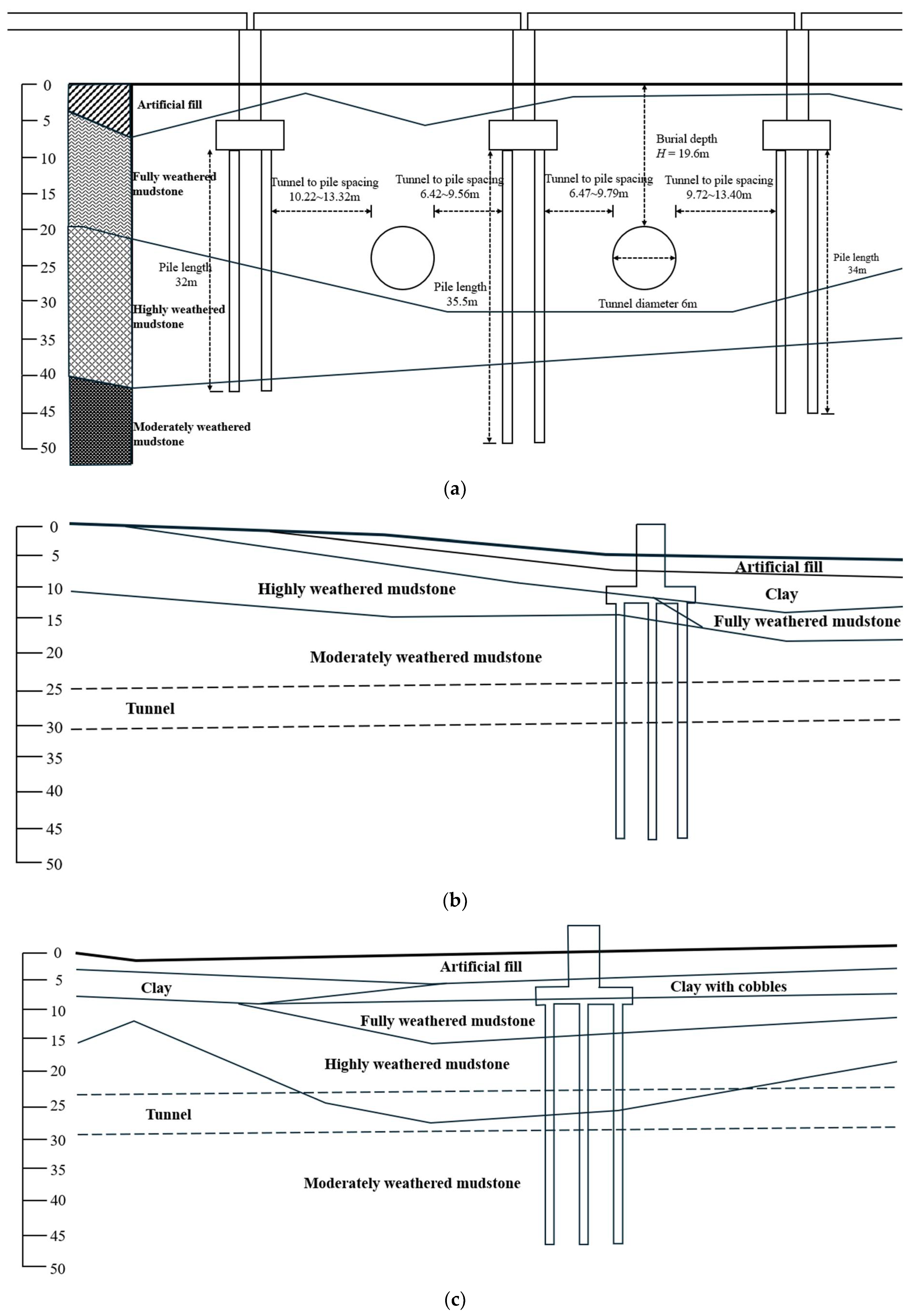
2.1. Railway and Tunnel Crossing Overview

The Yinyu Road to Longquan Station section of Phase I in the construction of Chengdu Metro Line 30 involves the intersection of the metro’s left and right tunnels with a railway bridge. The designed diameter of both metro tunnels is 6.0 m, and they intersect with the railway at angles of 66.6° and 65.2°, respectively. In this intersection section, the minimum distance between the shield tunnel and the existing bridge pile foundation is 6.42 m. To ensure the safety of railway operations during shield-driven tunnel construction, the design incorporated 219 mm diameter steel pipe isolation piles spaced at 1 m intervals to reinforce the railway bridge piers. The intersection relationship between the tunnel and the railway is depicted in Figure 1.

2.2. Engineering Geology and Hydrogeology

The geological unit at the project site is the River Alluvial Plain III-level terrace, characterized by relatively large variations in terrain and simple topographic conditions. The ground elevation ranges from 508.66 m to 534.57 m, with a relative height difference of approximately 25 m.
The surface layer at this site is primarily composed of newly deposited artificial fill (Q4mL). Below that, there are organic-rich soils and clays of the Middle and Lower Pleistocene Buried Water Deposit and Alluvial Layer (Q1+2fgl+al). These layers are underlain by the Formation (K2j) of the Upper Cretaceous System, which comprises sandstone, mudstone, and gravel-bearing mudstone. The geological composition of the site is complex, including miscellaneous fill soil, organic-rich soil, clay (hard plastic), clay with cobbles (hard plastic), fully weathered sandstone, highly weathered sandstone, moderately weathered sandstone, fully weathered mudstone, highly weathered mudstone, moderately weathered mudstone, and fully weathered gravel-bearing mudstone.
Surface water at the project site is predominantly sourced from a Flood Diversion Channel with a width of 5 m. Currently, the riverbanks are lined with mortar-set cobblestone retaining walls. The river has undergone artificial modification. The railway line intersects between YDK36+000 and YDK36+005, and it is a branch of the Dongfeng Channel. In some sections, the railway line passes through irrigation ditches and fishponds. The main source of groundwater at the site is fractured bedrock groundwater, with depths ranging from 0.2 m to 13.5 m. The stable elevation of the groundwater varies from 498.99 m to 530.07 m.

3. Isolated Pile Reinforcement and Its Finite Element Modelling

3.1. FE Model Parameters
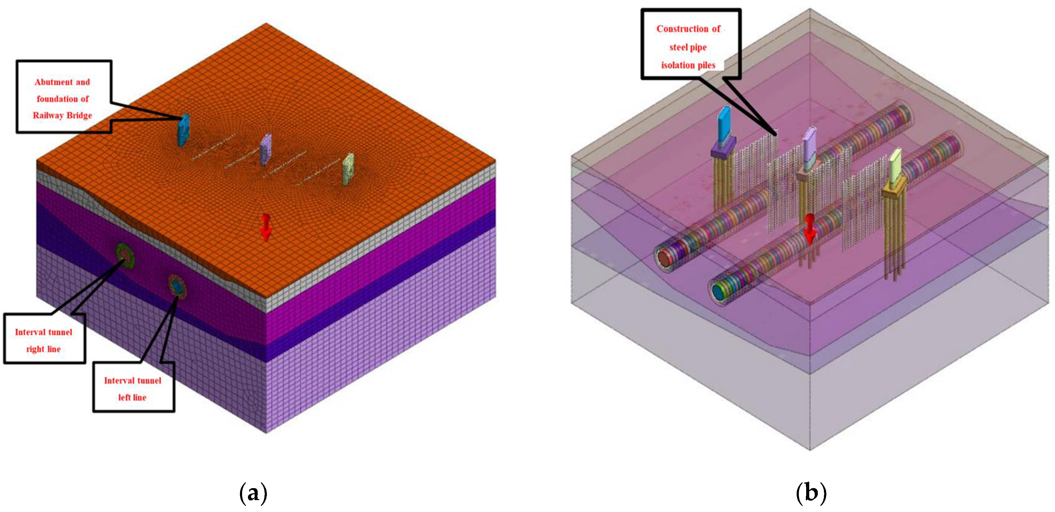
The Mohr–Coulomb model was selected as the constitutive model for the soil in this numerical simulation. The tunnel segment concrete is classified as C50 in strength grade. To account for the effects of bolt connections in the segments, the elastic modulus was reduced by a factor of 0.85. The parameters for this numerical simulation were determined based on the relevant literature and geological survey reports, as listed in Table 1.

3.2. FE Model

Based on the current engineering scenario, the longitudinal length along the railway line and the transverse width perpendicular to the railway line of the model were 160 m and 120 m, respectively. The model’ bottom boundary was established at 30 m beneath the proposed subway, while its upper surface corresponded to the ground surface. In this study, three-dimensional (3D) numerical simulation of the construction process of shield interval project was conducted using Midas GTS 2021. Figure 2 depicts the locations of existing railway bridge foundations, piers, and steel pipe isolation piles.
Lateral restrictions were imposed on the front, rear, and side boundaries of the model, while vertical restrictions were applied to the bottom boundary. The ground surface was set to be free within the model. Soil layers, tunnel linings, and other structures in the model were simulated using elastic–plastic solid elements that follow the Mohr–Coulomb criterion. Pile foundations and steel pipe isolation piles were simulated using beam elements, with interface elements added to effectively simulate the interaction between the piles and the surrounding soil. The 3D model and its relative positions are presented in Figure 3.
During the shield tunnel excavation process, each excavation step covered a length of 1.5 m. The entire tunnel was divided into 80 rings, with the excavation carried out in 80 steps. Upon excavating the first ring, the shield shell of that ring was activated. When the second ring was excavated, the shield shell of the second ring was activated while the shield shell of the first ring was deactivated, followed by the activation of the segmental lining and grouting in the first ring. This process was repeated continuously until the entire tunnel excavation was completed.

3.3. Simulation of Operating Conditions

The numerical model thoroughly portrayed the shield tunnelling procedure from initiation to completion. The main process of numerical simulation model construction is shown in Figure 4. Firstly, Figure 4a indicates the initial condition, in which the tunnel structure is not activated; Figure 4b indicates the addition of the bridge pile structure; Figure 4c indicates the addition of the added tunnel isolation piles. The shield construction process for the right and left lines are shown in Figure 5 and Figure 6, respectively. Each line contains five construction phases: tunneling towards the bridge piles; shield head approaching the bridge piles; shield traversing the bridge piles; shield tail dragging out of the bridge pile influence area; and shield safely traversing and driving away from the bridge pile influence area. It precisely captured the deformation of the railway at different stages of construction by focusing on the deformations before and after shield interval passing underneath the existing railway, as depicted in Figure 4, Figure 5 and Figure 6.

4. Deformation Analysis of Railway Bridge during the Tunnel Undercrossing Construction Process

4.1. Analysis of Calculations

(1)
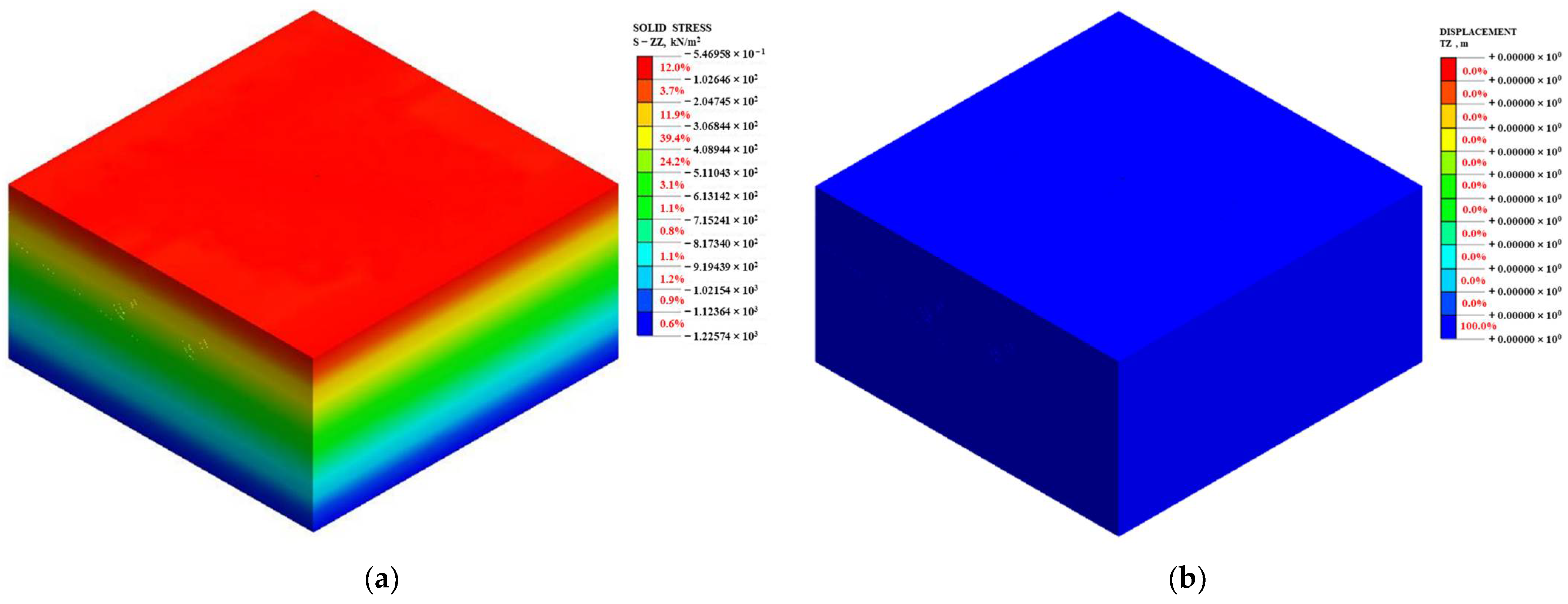
Phase 1: Calculation of initial ground stress
To obtain the initial state of the soil before the tunnel construction at the intersection section, and to reset the existing structural displacements, preparation was made for subsequent construction simulations. The stress and displacement nephograms in the initial state are shown in Figure 7.
(2)
Phase 2: Simulation of railway condition
The distributions of structural and principal stresses within the bridge were obtained by performing simulations of the construction stages of bridge piers and pile foundations, which are illustrated in Figure 8.
(3)
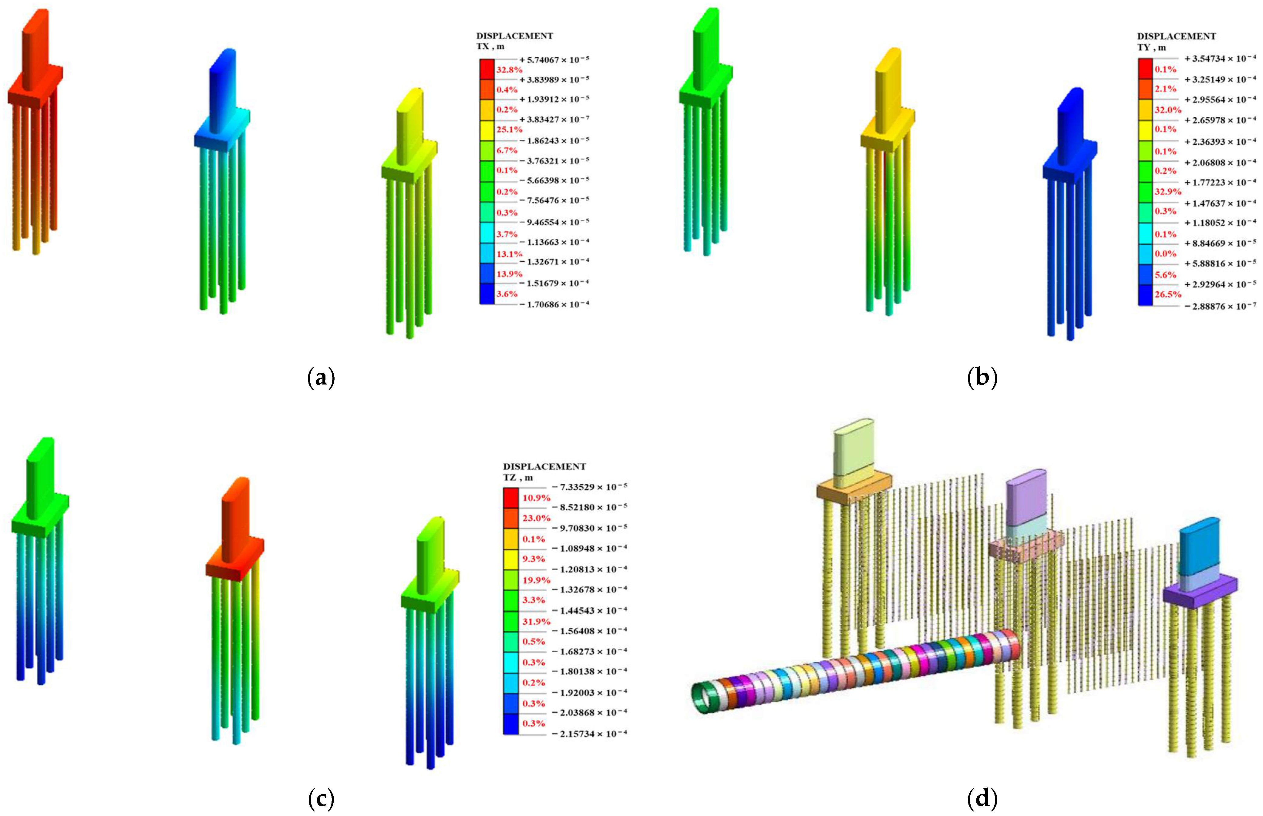
Phase 3: Installation of steel pipe isolation piles
Steel pipe isolation piles with a diameter of 219 mm and a spacing of 1 m were strategically installed beneath the bridge to assess the impact of isolation pile reinforcement construction on the deformation of railway bridge. The displacement nephograms of the railway bridge and the schematic diagram of the installation of steel pipe isolation piles are presented in Figure 9.
Figure 9 reveals that the construction of steel pipe isolation piles resulted in maximum horizontal and longitudinal displacements of 0.06 mm and a maximum vertical displacement of −0.31 mm for the bridge. It should be noted that these displacements fell within the expected range, which would not raise a safety concern.
(4)
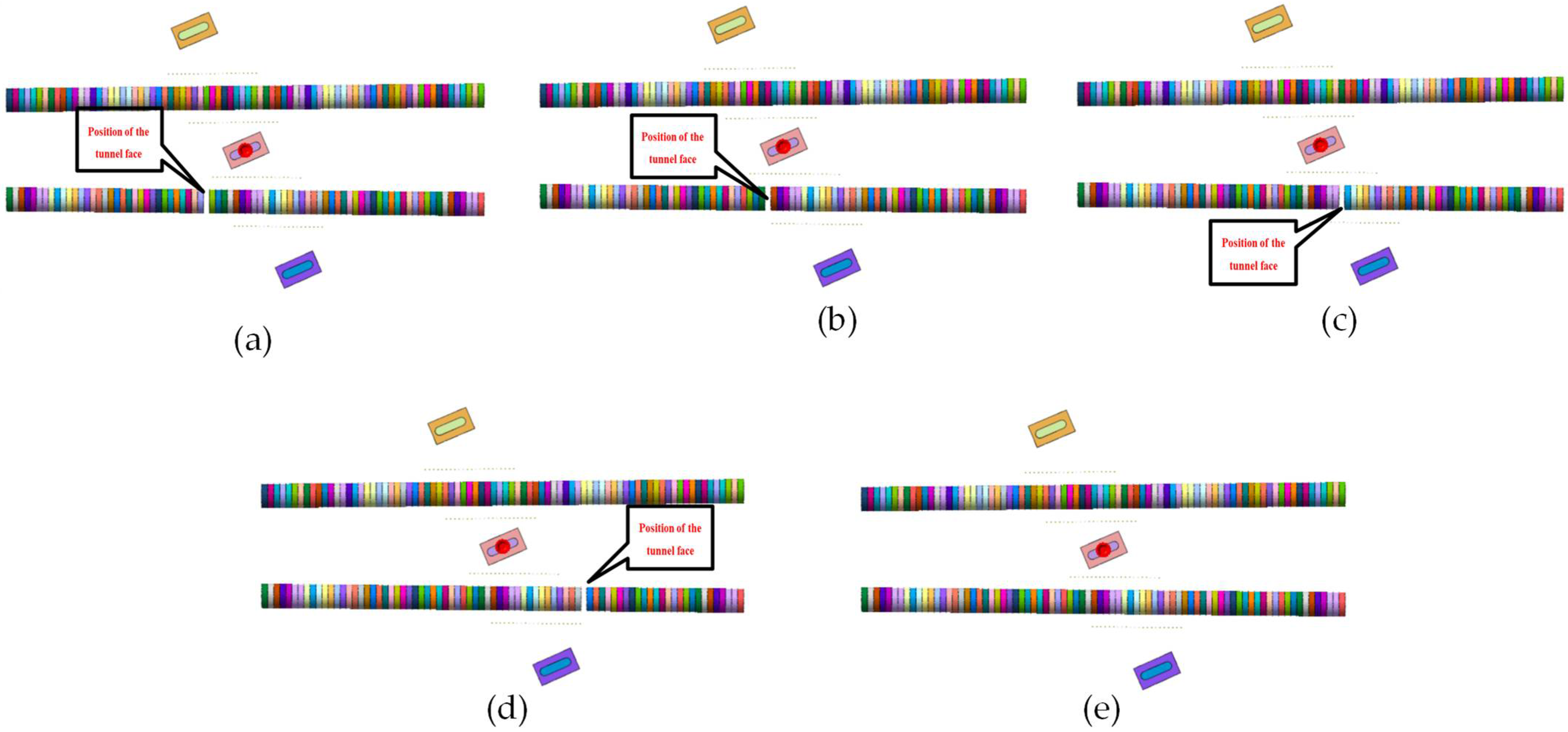
Phase 4: Excavating the right line of the interval to the starting point of isolation piles
To examine how the deformation of the current railway bridge affects the development of the right boundary line, we extracted deformation nephograms of the railway structures and a schematic diagram of the shield tunneling position, as illustrated in Figure 10.
Figure 10 reveals that there were maximum horizontal and vertical displacements of 0.35 mm at the middle abutment when the right line of the interval was excavated to the starting point of steel pipe isolation piles. There was a downward displacement of 0.22 mm exhibited by the bridge, which was primarily attributed to the settling of the bridge’s foundation.
(5)
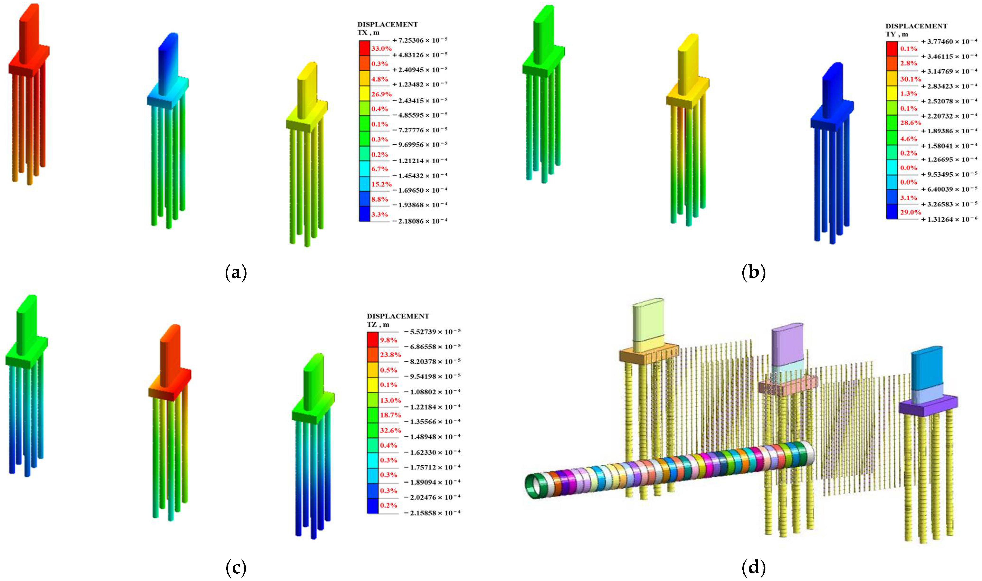
Phase 5: Excavating the right line of the interval to the nearest point of the bridge foundation
To analyze the deformation of the existing railway bridge when the right line of the interval was excavated to the nearest point of the bridge foundation, the deformation cloud of the railway structure and a schematic diagram of the shield tunneling position were extracted, as presented in Figure 11.
Figure 11 depicts that when the right line of the interval was excavated to the nearest point of the bridge abutment, the bridge experienced maximum horizontal and longitudinal displacements of 0.38 mm, primarily concentrated at the central bridge abutment. The bridge foundation experienced a peak downward displacement of 0.22 mm, indicating a significant vertical subsidence of the foundation structure.
(6)
Phase 6: Excavation of the right line of the interval underneath the bridge
To examine the deformation of railway bridge when the right line of the interval was excavated underneath the structure, deformation nephograms of the railway structures and a schematic diagram of the shield tunneling position were extracted, as illustrated in Figure 12.
As depicted in Figure 12, when the right line of the interval was excavated beneath the bridge, the bridge experienced maximum horizontal and longitudinal displacements of 0.36 mm, primarily concentrated at the central bridge abutment. The maximum vertical displacement of the bridge foundation was −0.22 mm, indicating significant vertical settlement of the bridge foundation.
(7)
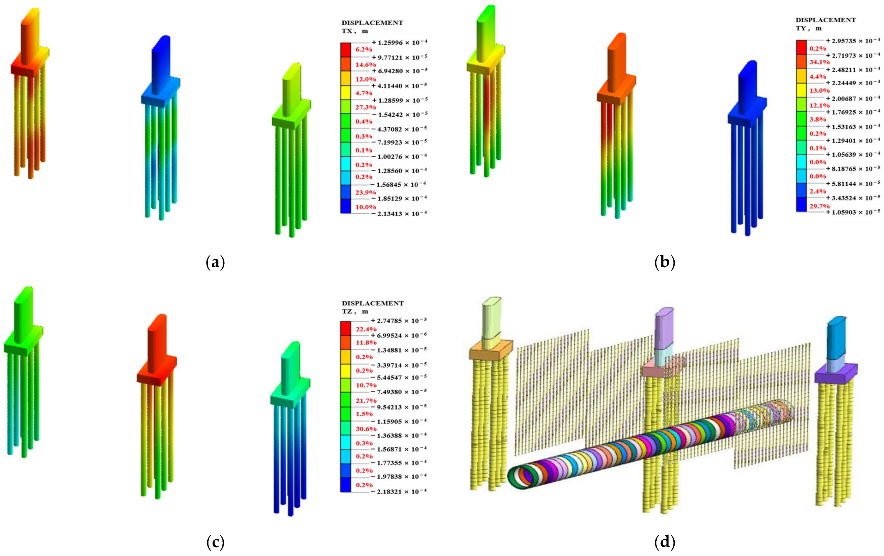
Phase 7: Excavating the right line of the interval to the ending point of isolation piles
To examine the impact of the deformation caused by excavating the right line of the interval to the ending point of isolation piles on the adjacent railway bridge, the structural deformation nephograms, as well as the schematic diagram of the shield tunneling position, were extracted, as presented in Figure 13.
Figure 13 reveals when the right line of the interval was excavated to the ending point of the steel pipe isolation piles, the bridge experienced maximum horizontal and longitudinal displacements of 0.30 mm, primarily concentrated at the central bridge abutment. The maximum vertical displacement of the bridge foundation was −0.22 mm, indicating a significant vertical settlement of the bridge foundation.
(8)
Phase 8: Completed construction of the right line of the interval
To analyze the deformation of the existing railway bridge after the completion of the right line’s construction, deformation nephograms of the railway structures and a schematic diagram of the shield tunneling position were extracted, as shown in Figure 14.
Figure 14 demonstrated that after the completion of the right line, the bridge underwent its greatest lateral and longitudinal shifts, reaching 0.25 mm, primarily around the central bridge abutment. A noticeable vertical subsidence of the bridge foundation was denoted by the peak vertical displacement at −0.23 mm.
(9)
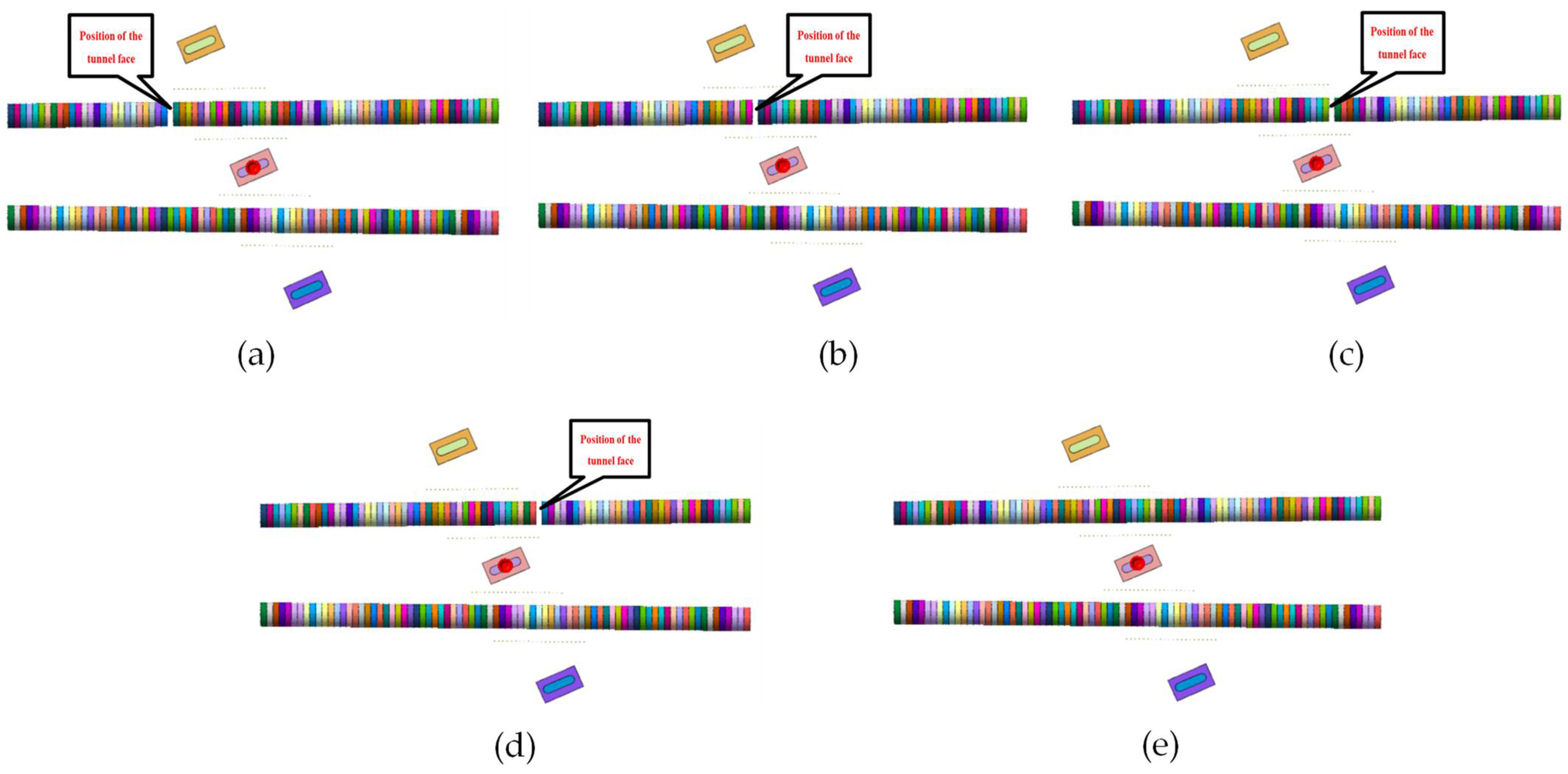
Phase 9: Excavating the left line of the interval to the starting point of the isolation piles
To analyze the deformation of the existing railway bridge during the construction of the left line of the interval up to the starting point of steel pipe isolation piles, deformation nephograms of the railway structures and a schematic diagram of the shield tunneling position were extracted, as presented in Figure 15.
According to Figure 15, during the left line’s construction up to the starting point of the steel pipe isolation piles, the bridge experienced maximum horizontal and longitudinal displacements of 0.33 mm, primarily concentrated at the central bridge abutment. The bridge’s largest vertical movement was recorded at −0.21 mm, which reflected considerable settling at the foundation level.
(10)
Phase 10: Excavation of the left line of the interval underneath the bridge
To analyze the deformation of the existing railway bridge during the construction of the left line underneath the main bridge, deformation nephograms of the railway structures and a schematic diagram of the shield tunneling position were extracted, as shown in Figure 16.
According to Figure 16, during the construction of the left line underneath the main bridge, the bridge experienced maximum horizontal and longitudinal displacements of 0.43 mm, which were mainly concentrated at the central bridge abutment. The bridge’s principal vertical deflection reached −0.17 mm, which was predominantly due to the vertical subsidence of its foundation.
(11)
Phase 11: Excavation of the left line of the interval to the nearest point of the bridge foundation
To analyze the deformation of the existing railway bridge during the construction of left line up to the nearest point of the bridge foundation, deformation nephograms of the railway structures and a schematic diagram of the shield tunneling position were extracted, as shown in Figure 17.
Figure 17 confirms that during the construction of the left line up to the nearest point of the bridge foundation, the bridge experienced maximum horizontal and longitudinal displacements of 0.47 mm, mainly concentrated at the central bridge abutment. The bridge’s principal vertical deflection reached −0.16 mm, which was primarily attributed to the vertical subsidence of its foundation.
(12)
Phase 12: Excavating the left line of the interval to the ending point of isolation piles
To analyze the deformation of the existing railway bridge during the construction of the left line up to the ending point of the steel pipe isolation piles, deformation nephograms of the railway structures and a schematic diagram of the shield tunneling position were extracted, as shown in Figure 18.
It can be observed from Figure 18 that during the construction of the left line up to the ending point of the steel pipe isolation piles, the bridge experienced maximum horizontal and longitudinal displacements of 0.47 mm, mainly concentrated at the central bridge abutment. The bridge’s principal vertical deflection reached −0.15 mm, which was predominantly due to the vertical subsidence of its foundation.
(13)
Phase 13: Completed construction of the left line of the interval
To analyze the deformation of the existing railway bridge after the completion of the left line’s construction, deformation nephograms of the railway structures and a schematic diagram of the shield tunneling position were extracted, as shown in Figure 19.
It was determined from Figure 19 that upon completion of the left line’s construction, the railway bridge exhibited maximum horizontal and longitudinal displacements of 0.26 mm, primarily concentrated at the central bridge pier. The greatest vertical displacement of the bridge was −0.16 mm, which was mainly attributed to the vertical sinking of the bridge’s foundation.

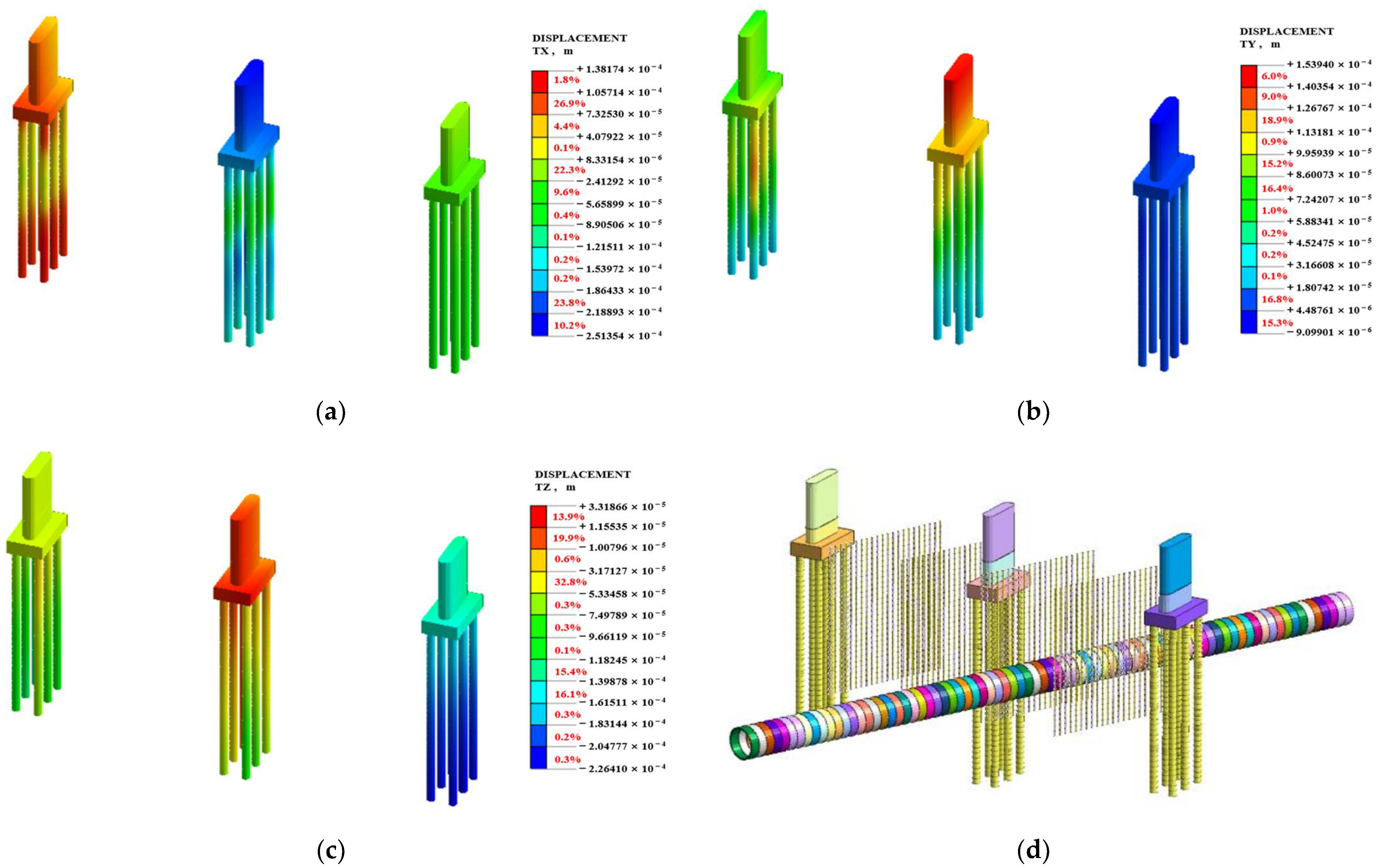
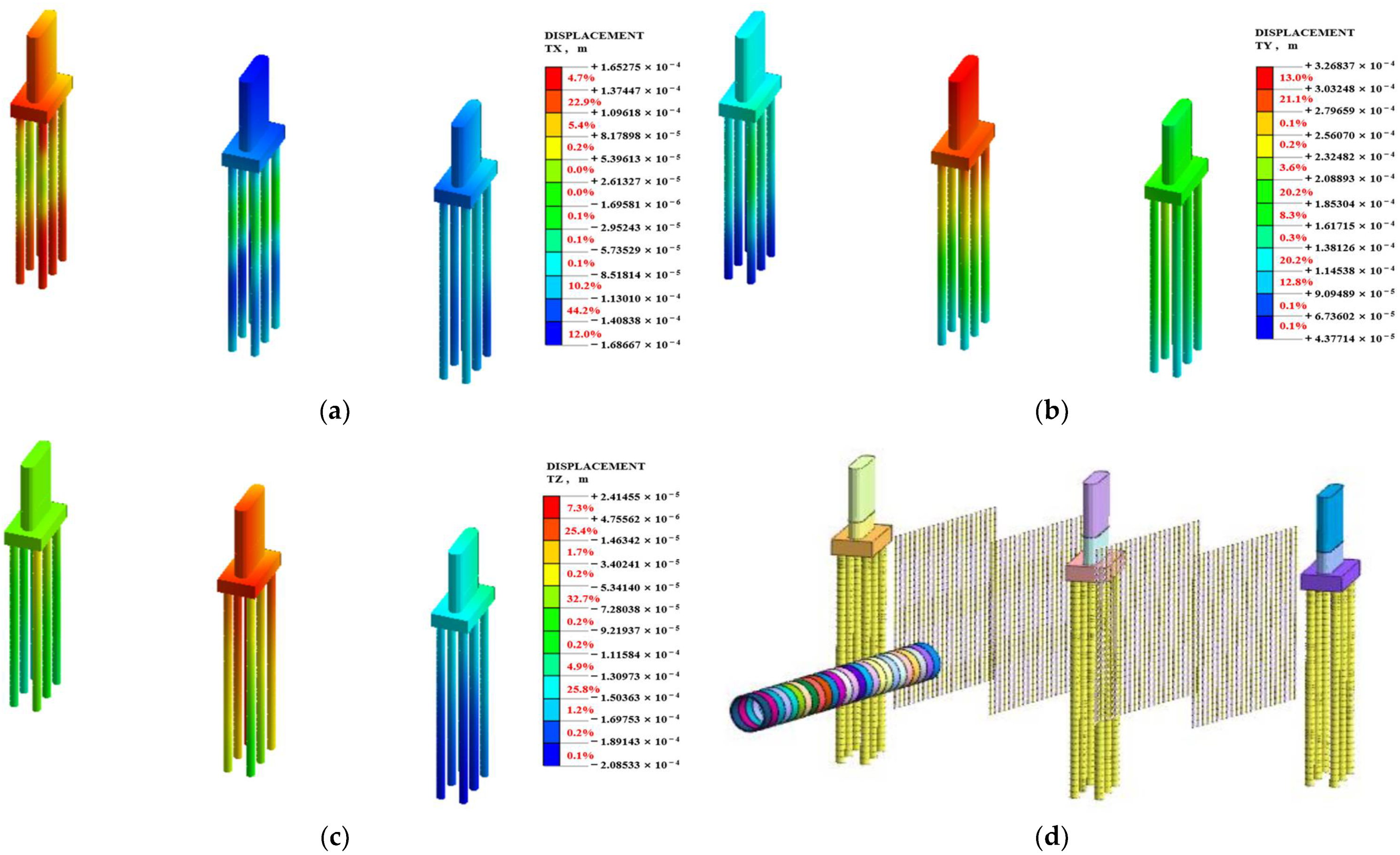
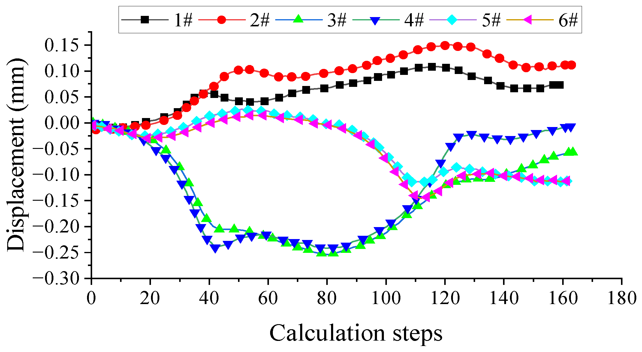
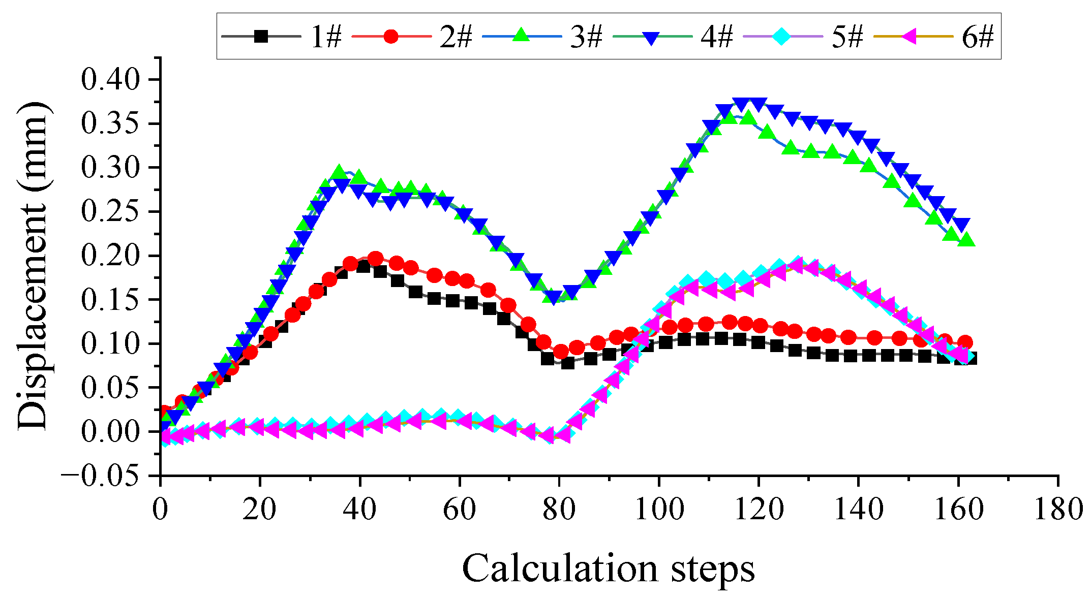
4.2. Deformation of Existing Railway Bridge

To examine the effect of shield tunnel excavation on the railway bridge, we extracted time-dependent vertical and horizontal displacements of bridge piers. The locations of the data extraction points and the corresponding time-dependent curves are presented in Figure 20, Figure 21, Figure 22 and Figure 23, respectively.
As the excavation of the left and right tunnel lines was completed, the bridge deformation exhibited a clear trend towards stabilization. Displacement data recorded from the pier tops at measuring points 1–6 indicated a maximum horizontal movement of 0.38 mm and a maximum vertical displacement of 0.16 mm. During the shield tunneling beneath the existing railway bridge, detailed monitoring revealed that the measured horizontal displacement reached 0.42 mm, while the vertical displacement peaked at 0.25 mm. In the model, some vertical displacement values were observed to be above zero, which can be attributed to the installation of steel pipe piles and the thrust of the shield machine during the tunneling process. These factors caused soil deformation in the model, leading to a slight upward movement of the pier foundations. Although these measured values slightly exceeded the model predictions, the overall trends and magnitudes were closely aligned, remaining well within the permissible limits of +3.0 to −8.0 mm for vertical movement at the pier top, and ±7.0 mm for both vertical and horizontal movements at the pier top and base. These findings confirm the validity of the finite element model in accurately predicting bridge deformation, underscoring its reliability as a tool for guiding similar construction projects.

5. Protection Measures during Shield Tunnel Underpass

5.1. Shield Tunnel Construction Control

Minimizing ground losses and deformations caused by shield tunnel construction plays a crucial role in protecting structures and underground pipelines. The key tasks involve effectively controlling shield excavation parameters, improving grouting quality, and optimizing the timing of grouting [47,48,49,50,51,52]. It is recommended to establish a trial section, where feasible, to determine the optimal excavation parameters.

5.1.1. Shield Excavation Parameters

Appropriate excavation parameters should be carefully determined and strictly controlled based on the geological conditions of the overlying strata and those traversed by the shield tunnel. These parameters include cutterhead rotation speed, torque, jacking force, screw conveyor speed, additive selection, and injection volume. It is essential to closely monitor and record soil pressures on the cutterhead face and soil chamber, excavation volume, and soil conditions. The collected data should be fed back to the shield control center to facilitate timely adjustments or optimizations of the excavation parameters. Effective management of excavation materials should be implemented, necessitating a comprehensive analysis of excavation and backfilling data. For sections intersecting critical structures or pipelines, strict adherence to both the “quality” and “volume” control criteria is imperative to ensure that ground losses or deformations are maintained within acceptable limits. Prior to traversing important structures or pipelines, it is essential to inspect cutterhead wear while maintaining a consistent and continuous rate of advancement to uphold balanced soil pressures on the tunnel face.

5.1.2. Synchronous Tail Grouting and Secondary Grouting in the Tunnels

After the tunnel segments are extracted from the shield tail, immediate synchronous grouting with an appropriate increase in grout volume should be conducted to completely fill all gaps between the tunnel segments and the surrounding strata. When approximately 10 ring segments of the tunnel lining are assembled, a secondary grouting should be carried out to provide an effective grout filling of the gaps between the synchronous grouting layer and the surrounding strata. Supplementary grouting may be repeated if necessary.

5.1.3. Construction of Curve Sections

To mitigate the adverse effects of over-excavation and excessive realignment during the construction of curve sections, it is recommended to appropriately reduce the shield excavation speed and implement timely realignment measures. The philosophy of making multiple and smaller adjustments should be employed to minimize the impact. In addition, the grout volume for synchronous tail grouting and secondary grouting in tunnels should be adjusted accordingly.

5.2. Tracking Routing

In addition to the aforementioned technological measures, it is recommended to incorporate real-time monitoring during grouting operations (i.e., synchronous stratum compensation grouting) as an effective supplementary measure to reduce construction risks, and to make necessary preparations for materials. Based on experimental results, the potential impact zone of stratum fracture during shield tunneling should be considered as the targeted range for tracking grouting. During the grouting process, attention should be paid to controlling the grouting pressure to prevent excessively high pressure that may damage the building foundations and pipeline structures.

5.3. Cavity Grouting

Cavity grouting was conducted within the tunnel by creating grouting holes on the tunnel segment of the shield tunneling machine. Grouting pipes were then installed through these holes, including lifting holes, to inject grout into the surrounding soil within a certain range of the tunnel. The grouting pipes used can be 42 mm diameter steel pipes with a minimum length of 3.5 m for gravel layers and 2.5 m for clay layers. Cement-based single-liquid grout is recommended as the grouting material, and in special emergency situations, rapid-setting materials are suggested. The specifics of grouting, such as the mixture ratio of the grout, the applied pressure, the order of injection, time spent, and the amount of grout used, were established from on-site experimental outcomes and were further refined throughout the grouting operation in response to data obtained from surveillance feedback. To ensure the effectiveness of cavity grouting within the tunnel, it is important to prioritize timely execution to prevent excessive ground loss or collapse extension that may hinder the achievement of the desired outcomes.

5.4. Mid-Shield Grouting

In special sections where sensitive structures and pipelines prone to settlement are located beneath the shield tunnel, shield grouting was performed by injecting plastic or inert grout through shield grouting holes synchronously during excavation. This timely compensation helped reduce disturbance to the surrounding soil and effectively filled the construction voids created during shield tunneling.

5.5. Quality Control Measures

During the construction process, rigorous quality control measures were implemented to ensure the integrity of the project and to mitigate potential risks. Key measures included the strict regulation of the construction sequence, requiring written records and inspection certifications for site commencement and concealed works; thorough inspection of incoming materials, such as concrete and steel, to ensure compliance with quality standards; and the adoption of a “three-level inspection” system, consisting of self-inspection, mutual inspection, and handover inspection, to verify that each stage of the process meets the required standards. These measures, supported by comprehensive documentation and monitoring, ensured that construction quality was consistently maintained.

5.6. Monitoring of Railway Bridge

Railway bridge monitoring must strictly follow specified technical standards such as TB 10314-2021 [53] and TB 10182-2017 [54]. These standards detail monitoring items, frequencies, warning, alarm, and control thresholds for displacements of bridges and tracks. For conventional-speed railway projects, bridge pier vertical displacement and track vertical displacement are critical, with allowable tolerances of +3 mm to −8 mm and horizontal displacements within ±7 mm. During construction, a multi-tiered early warning system is implemented to ensure safety. This system operates by issuing warnings as displacement values approach certain thresholds. At 80% of the threshold, a Level 1 warning is triggered, signaling the need for closer monitoring. When displacements reach 90% of the limit, a Level 2 warning prompts immediate adjustments to construction activities, such as modifying excavation speeds or increasing grouting efforts. If displacements exceed the allowable limits, a Level 3 alarm is activated, requiring an immediate halt to construction and the execution of emergency protocols. Real-time monitoring data are continuously transmitted to the control center, allowing for construction managers to make timely adjustments to shield tunneling parameters. An automated alarm system is also integrated with construction equipment, ensuring that tunneling operations are paused if critical thresholds are breached. In the event of excessive displacements, emergency response measures, such as structural reinforcement, are ready for immediate implementation to protect the bridge and ensure construction safety.

6. Conclusions

This study concluded that the construction of a double-line shield tunnel beneath an existing railway bridge can be effectively managed to minimize the impact on the bridge’s structural integrity. Through the utilization of finite element software for computational simulation, the research demonstrated that the implementation of reinforcement measures such as steel pipe isolation piles and rigorous construction quality control can control bridge deformation within acceptable limits. The vertical and horizontal displacements observed during various construction phases were determined to be minimal, thereby guaranteeing the safe operation of the railway. The following conclusions were obtained:
(1)
The bridge’s movements and shape alterations during construction met the requirements with the requirements of Standard TB 10314-2021, where vertical displacements fall within the required range of +3.0 mm to −8.0 mm for the pier cap and ±7.0 mm for both the vertical and horizontal movements at the pier top and base.
(2)
Numerical simulations taking into account the reinforcement measures revealed that the maximum horizontal and longitudinal displacements of the bridge were 0.06 mm, while the maximum vertical displacement value was −0.31 mm. It could be concluded that the construction quality of isolation piles significantly affected the deformation of the existing railway bridge resulting from the subsequent construction of the shield tunnel.
(3)
The numerical simulation results indicated that the deformation of the railway bridge pier foundation due to tunnel construction was minimal. The bridge experienced maximum horizontal and longitudinal displacements of up to 0.47 mm and vertical displacements of up to −0.23 mm during various construction phases.
This study provides valuable guidance and reference for future projects involving tunnel construction in proximity to existing structures, mainly in terms of providing an overall research framework for the study of the impacts of tunnel construction on the surrounding area, and it underscores the importance of reinforcement measures, quality control, and continuous monitoring to ensure safety and minimize structural response. However, this paper is partially deficient in that it is not compared with other methods (e.g., machine learning) to further validate the effectiveness of the models constructed in this paper. Additionally, the effect of optimization measures on deformation was not considered. In the future, non-linear mappings between optimization measures and deformation can be constructed by machine learning methods to further determine the optimization measures to be employed.

Author Contributions

Methodology, W.L.; Software, L.Z.; Validation, H.-A.Z.; Formal analysis, W.L., L.Z. and W.-L.L.; Investigation, W.L. and L.Z.; Data curation, W.L., L.Z. and X.-C.Y.; Writing—original draft, W.L. and H.-A.Z.; Writing—review and editing, W.L. and W.-L.L.; Visualization, H.-A.Z.; Project administration, W.L. and X.-C.Y.; Funding acquisition, W.-L.L. All authors have read and agreed to the published version of the manuscript.

Funding

The authors gratefully acknowledge the support provided by the National Natural Science Foundation of China (Grant No. 72171094 and 5219266), the Hubei-National Joint Fund for Regional Innovation and Development Key Support Projects (Grant No. U21A20151), and the 2024 Pre-approved Project of Hubei Social Science Foundation, Special Project on the Rule of Law in Hubei.

Data Availability Statement

The data used to support the findings of this study are included within the article. Should further data or information be required, these are available from the corresponding author upon request.

Conflicts of Interest

Authors Wen Liu, Lu Zhao and Xiang-Chuan Yao were employed by the company CCCC Wuhan ZhiXing International Engineering Consulting Co., Ltd. The remaining authors declare that the research was conducted in the absence of any commercial or financial relationships that could be construed as a potential conflict of interest.

References

  1. Di, Z.; Li, L.; Li, M.; Zhang, S.; Yan, Y.; Wang, M.; Li, B. Research on the contribution of metro-based freight to reducing urban transportation exhaust emissions. Comput. Ind. Eng. 2023, 185, 109622. [Google Scholar] [CrossRef]
  2. Zhou, Y.; Chen, J.; Zhong, M.; Li, Z.; Zhou, W.; Zhou, Z. Risk analysis of crowd gathering on metro platforms during large passenger flow. Tunn. Undergr. Space Technol. 2023, 142, 105421. [Google Scholar] [CrossRef]
  3. Yu, X.; Chen, Z.; Liu, F.; Zhu, H. How urban metro networks grow: From a complex network perspective. Tunn. Undergr. Space Technol. 2023, 131, 104841. [Google Scholar] [CrossRef]
  4. Xu, Q.; Xu, S.; Li, Y.; Zhang, Y.; Tian, H.; Zhao, M. Deformation control strategies for shield tunnel underpassing viaduct of high-speed railway: A case study. J. Eng. Res. 2023. [Google Scholar] [CrossRef]
  5. Yan, B.; Wang, R.; Wang, Y. Deformation of adjacent buildings and ground settlement induced by shield construction of three-line small-spacing tunnels. Alex. Eng. J. 2023, 79, 237–251. [Google Scholar] [CrossRef]
  6. Khabbaz, H.; Gibson, R.; Fatahi, B. Effect of constructing twin tunnels under a building supported by pile foundations in the Sydney central business district. Undergr. Space 2019, 4, 261–276. [Google Scholar] [CrossRef]
  7. Li, P.; Lu, Y.; Lai, J.; Liu, H.; Wang, K. A Comparative Study of Protective Schemes for Shield Tunneling Adjacent to Pile Groups. Adv. Civ. Eng. 2020, 2020, 6964314. [Google Scholar] [CrossRef]
  8. Zhang, L.; Wu, X.; Qin, Y.; Skibniewski, M.J.; Liu, W. Towards a Fuzzy Bayesian Network Based Approach for Safety Risk Analysis of Tunnel-Induced Pipeline Damage. Risk Anal. 2016, 36, 278–301. [Google Scholar] [CrossRef]
  9. Jin, D.; Yuan, D.; Li, X.; Zheng, H. Analysis of the settlement of an existing tunnel induced by shield tunneling underneath. Tunn. Undergr. Space Technol. 2018, 81, 209–220. [Google Scholar] [CrossRef]
  10. Liu, W.; Ding, L. Global sensitivity analysis of influential parameters for excavation stability of metro tunnel. Autom. Constr. 2020, 113, 103080. [Google Scholar] [CrossRef]
  11. Lai, J.; Zhou, H.; Wang, K.; Qiu, J.; Wang, L.; Wang, J.; Feng, Z. Shield-driven induced ground surface and Ming Dynasty city wall settlement of Xi’an metro. Tunn. Undergr. Space Technol. 2020, 97, 103220. [Google Scholar] [CrossRef]
  12. Simic Silva, P.T.; Martínez Bacas, B.; Galindo Aires, R.; Simic, D. 3D simulation for tunnelling effects on existing piles. Comput. Geotech. 2020, 124, 103625. [Google Scholar] [CrossRef]
  13. Cheng, W.C.; Li, G.; Liu, N.; Xu, J.; Horpibulsuk, S. Recent massive incidents for subway construction in soft alluvial deposits of Taiwan: A review. Tunn. Undergr. Space Technol. 2020, 96, 103178. [Google Scholar] [CrossRef]
  14. Liu, W.; Li, A.; Fang, W.; Love, P.E.D.; Hartmann, T.; Luo, H. A hybrid data-driven model for geotechnical reliability analysis. Reliab. Eng. Syst. Saf. 2023, 231, 108985. [Google Scholar] [CrossRef]
  15. Liu, W.; Chen, E.J.; Yao, E.; Wang, Y.; Chen, Y. Reliability analysis of face stability for tunnel excavation in a dependent system. Reliab. Eng. Syst. Saf. 2021, 206, 107306. [Google Scholar] [CrossRef]
  16. He, S.; Lai, J.; Li, Y.; Wang, K.; Wang, L.; Zhang, W. Pile group response induced by adjacent shield tunnelling in clay: Scale model test and numerical simulation. Tunn. Undergr. Space Technol. 2022, 120, 104039. [Google Scholar] [CrossRef]
  17. Li, Z.; Chen, Z.; Wang, L.; Zeng, Z.; Gu, D. Numerical simulation and analysis of the pile underpinning technology used in shield tunnel crossings on bridge pile foundations. Undergr. Space 2021, 6, 396–408. [Google Scholar] [CrossRef]
  18. Yoo, C. Interaction between tunneling and bridge foundation—A 3D numerical investigation. Comput. Geotech. 2013, 49, 70–78. [Google Scholar] [CrossRef]
  19. Huang, K.; Sun, Y.W.; Zhou, D.Q.; Li, Y.J.; Jiang, M.; Huang, X.Q. Influence of water-rich tunnel by shield tunneling on existing bridge pile foundation in layered soils. J. Cent. South Univ. 2021, 28, 2574–2588. [Google Scholar] [CrossRef]
  20. Wang, Z.; Zhang, K.W.; Wei, G.; Li, B.; Li, Q.; Yao, W.J. Field measurement analysis of the influence of double shield tunnel construction on reinforced bridge. Tunn. Undergr. Space Technol. 2018, 81, 252–264. [Google Scholar] [CrossRef]
  21. Wu, K.; Shao, Z.; Li, C.; Qin, S. Theoretical Investigation to the Effect of Bolt Reinforcement on Tunnel Viscoelastic Behavior. Arab. J. Sci. Eng. 2020, 45, 3707–3718. [Google Scholar] [CrossRef]
  22. Fu, J.; Yang, J.; Zhu, S.; Shi, Y. Performance of Jet-Grouted Partition Walls in Mitigating the Effects of Shield-Tunnel Construction on Adjacent Piled Structures. J. Perform. Constr. Facil. 2017, 31, 04016096. [Google Scholar] [CrossRef]
  23. Wang, Z.; Xie, Y.; Liu, H.; Feng, Z. Analysis on deformation and structural safety of a novel concrete-filled steel tube support system in loess tunnel. Eur. J. Environ. Civ. Eng. 2021, 25, 39–59. [Google Scholar] [CrossRef]
  24. Yu, X.; Xing, G.; Chang, Z. Flexural behavior of reinforced concrete beams strengthened with near-surface mounted 7075 aluminum alloy bars. J. Build. Eng. 2020, 31, 101393. [Google Scholar] [CrossRef]
  25. Wang, X.; Lai, J.; He, S.; Garnes, R.S.; Zhang, Y. Karst geology and mitigation measures for hazards during metro system construction in Wuhan, China. Nat. Hazards 2020, 103, 2905–2927. [Google Scholar] [CrossRef]
  26. Liu, W.; Li, A.; Liu, C. Multi-objective optimization control for tunnel boring machine performance improvement under uncertainty. Autom. Constr. 2022, 139, 104310. [Google Scholar] [CrossRef]
  27. Zhao, B.; Wang, X.; Zhang, C.; Li, W.; Abbassi, R.; Chen, K. Structural integrity assessment of shield tunnel crossing of a Railway Bridge using orthogonal experimental design. Eng. Fail. Anal. 2020, 114, 104594. [Google Scholar] [CrossRef]
  28. Jiao, N.; Sun, S.; Liu, J.; Guo, Q.; Ding, J.; Wan, X. Analysis of existing railway deformation caused by double shield tunnel construction in soil–rock composite stratum. Energy Rep. 2023, 9, 159–165. [Google Scholar] [CrossRef]
  29. Ding, Z.; Zhang, M.-B.; Zhang, X.; Wei, X.-J. Theoretical analysis on the deformation of existing tunnel caused by under-crossing of large-diameter slurry shield considering construction factors. Tunn. Undergr. Space Technol. 2023, 133, 104913. [Google Scholar] [CrossRef]
  30. Gan, X.; Yu, J.; Gong, X.; Zhu, M. Probabilistic analysis for twin tunneling-induced longitudinal responses of existing shield tunnel. Tunn. Undergr. Space Technol. 2022, 120, 104317. [Google Scholar] [CrossRef]
  31. Gan, X.; Yu, J.; Gong, X.; Liu, N.; Zheng, D. Behaviours of existing shield tunnels due to tunnelling underneath considering asymmetric ground settlements. Undergr. Space 2022, 7, 882–897. [Google Scholar] [CrossRef]
  32. Fu, J.; Zhao, N.; Qu, Y.; Yang, J.; Wang, S. Effects of twin tunnel undercrossing excavation on the operational high speed railway tunnel with ballastless track. Tunn. Undergr. Space Technol. 2022, 124, 104470. [Google Scholar] [CrossRef]
  33. Jiang, X.; Zhu, H.; Yan, Z.; Zhang, F.; Ye, F.; Li, P.; Zhang, X.; Dai, Z.; Bai, Y.; Huang, B. A state-of-art review on development and progress of backfill grouting materials for shield tunneling. Dev. Built Environ. 2023, 16, 100250. [Google Scholar] [CrossRef]
  34. Liang, J.; Liu, W.; Yin, X.; Li, W.; Yang, Z.; Yang, J. Experimental study on the performance of shield tunnel tail grout in ground. Undergr. Space 2024. [Google Scholar] [CrossRef]
  35. Wu, T.; Gao, Y.; Zhou, Y. Application of a novel grouting material for prereinforcement of shield tunnelling adjacent to existing piles in a soft soil area. Tunn. Undergr. Space Technol. 2022, 128, 104646. [Google Scholar] [CrossRef]
  36. Liu, W.; Liu, F.; Fang, W.; Love, P.E.D. Causal discovery and reasoning for geotechnical risk analysis. Reliab. Eng. Syst. Saf. 2024, 241, 109659. [Google Scholar] [CrossRef]
  37. Zeng, Y.; Atangana Njock, P.G.; Xiong, W.; Zhang, X.-L.; Shen, S.-L. Risks analysis of large diameter slurry shield tunneling in urban area. Undergr. Space 2023, 13, 281–300. [Google Scholar] [CrossRef]
  38. Xu, J.; Zheng, L.; Song, G.; Zhang, D.; Sheil, B.; Marshall, A.M. Effects of embedded walls on tunnelling-induced sandy ground displacements: A numerical investigation. Géotechnique 2014. ahead of print. [Google Scholar] [CrossRef]
  39. Shan, Y.; Cheng, G.; Gu, X.; Zhou, S.; Xiao, F. Optimization of design parameters of displacement isolation piles constructed between a high-speed railway bridge and a double-line metro tunnel: From the view point of vibration isolation effect. Comput. Geotech. 2021, 140, 104460. [Google Scholar] [CrossRef]
  40. Kang, Y.; Geng, Z.; Chen, L.; Zhu, Y.; Li, K.; Liu, B. Ground Reinforcement Method for Closely Spaced Overlapping Tunnels Passing beneath High-Speed Railway Bridge. J. Geotech. Geoenviron. Eng. 2022, 148, 05022007. [Google Scholar] [CrossRef]
  41. Xu, J.; Gui, J.; Sheil, B. A numerical investigation of the role of basements on tunnel-frame interaction in sandy soil. Comput. Geotech. 2024, 169, 106197. [Google Scholar] [CrossRef]
  42. Jiang, P.W.; Zhang, Z.H.; Zheng, H.; Huang, J.K. Coupling analysis method of grouting construction with deformation response of adjacent existing tunnel. Undergr. Space 2024, 15, 312–330. [Google Scholar] [CrossRef]
  43. Zhang, Y.; Tao, L.; Liu, J.; Zhao, X.; Guo, F.; Tan, L.; Wang, Z. Construction techniques and mechanical behavior of newly-built large-span tunnel ultra-short distance up-crossing the existing shield tunnel with oblique angle. Tunn. Undergr. Space Technol. 2023, 138, 105162. [Google Scholar] [CrossRef]
  44. Lei, M.F.; Shi, Y.B.; Tang, Q.L.; Sun, N.X.; Tang, Z.H.; Gong, C.J. Construction control technology of a four-hole shield tunnel passing through pile foundations of an existing bridge: A case study. J. Cent. South Univ. 2023, 30, 2360–2373. [Google Scholar] [CrossRef]
  45. Liu, W.; Liang, J.; Xu, T. Tunnelling-induced ground deformation subjected to the behavior of tail grouting materials. Tunn. Undergr. Space Technol. 2023, 140, 105253. [Google Scholar] [CrossRef]
  46. Burd, H.J.; Yiu, W.N.; Acikgoz, S.; Martin, C.M. Soil-foundation interaction model for the assessment of tunnelling-induced damage to masonry buildings. Tunn. Undergr. Space Technol. 2022, 119, 104208. [Google Scholar] [CrossRef]
  47. Zhou, J.; Chai, J.-H.; Ding, X.-H.; Yu, S.-C.; Zhang, Y.-W. Construction prediction and dynamic control of shield tunnel. Chin. J. Geotech. Eng. 2019, 41, 821–828. [Google Scholar] [CrossRef]
  48. Ye, F.; Qin, N.; Gao, X.; Quan, X.Y.; Qin, X.Z.; Dai, B. Shield Equipment Optimization and Construction Control Technology in Water-Rich and Sandy Cobble Stratum: A Case Study of the First Yellow River Metro Tunnel Undercrossing. Adv. Civ. Eng. 2019, 2019, 8358013. [Google Scholar] [CrossRef]
  49. Huang, H.; Chang, J.; Zhang, D.; Zhang, J.; Wu, H.; Li, G. Machine learning-based automatic control of tunneling posture of shield machine. J. Rock Mech. Geotech. Eng. 2022, 14, 1153–1164. [Google Scholar] [CrossRef]
  50. Wan, Y.; Zhu, Z.; Song, L.; Song, S.; Zhang, J.; Gu, X.; Xu, X. Study on temporary filling material of synchronous grouting in the middle of shield. Constr. Build. Mater. 2021, 273, 121681. [Google Scholar] [CrossRef]
  51. Zhang, D.M.; Ye, Z.W.; Zhang, J.Z.; Li, J.P.; Jia, J.W. Influence of grouting on rehabilitation of an over-deformed shield tunnel lining in spatially variable soil. Comput. Geotech. 2022, 152, 104999. [Google Scholar] [CrossRef]
  52. Zheng, G.; Zhang, F.; Zhang, T.; Zha, W. Disturbance of shield tunnel excavation and compensation grouting to surrounding soil: Laboratory tests and numerical simulations. Chin. J. Geotech. Eng. 2016, 38, 1741–1753. [Google Scholar] [CrossRef]
  53. TB 10314-2021; Technical Specification for Safety Monitoring of Operating Railway Infrastructures with Adjacent Constructions. China Railway Publishing House: Beijing, China, 2021.
  54. TB 10182-2017; Technical Specification for Highway and Municipal Engineering under Crossing High Speed Railway. China Railway Publishing House: Beijing, China, 2017.
Figure 1. Tunnel cross-section and geological profile along the route: (a) tunnel geological cross-section; (b) left line tunnel geological cross-section; (c) right line tunnel geological cross-section.
Buildings 14 03024 g001
Figure 2. Three-dimensional diagram of the railway intersection section.
Buildings 14 03024 g002
Figure 3. Three-dimensional model and interrelationship diagram: (a) soil layers; (b) structures.
Buildings 14 03024 g003
Figure 4. Tunnel construction phases: (a) initial ground stress; (b) railway condition simulation; (c) isolation steel pile installation.
Buildings 14 03024 g004
Figure 5. For the right line of the interval: (a) excavation advances to starting point of isolation piles; (b) excavation advances to the nearest point of the bridge foundation; (c) excavation underneath the bridge; (d) excavation advances to ending point of isolation piles; (e) completion of the construction.
Buildings 14 03024 g005
Figure 6. For the left line of the interval: (a) excavation advances to starting point of isolation piles; (b) excavation underneath the bridge; (c) excavation advances to the nearest point of the bridge foundation; (d) excavation advances to ending point of isolation piles; (e) completion of the construction.
Buildings 14 03024 g006
Figure 7. Stress and displacement nephograms in the initial state: (a) rock mass stress nephogram in the Z direction in the initial state; (b) resetting of initial displacements.
Buildings 14 03024 g007
Figure 8. Structural and bridge principal stress nephogram: (a) maximum stress in structure; (b) minimum stress in structure; (c) maximum stress in bridge; (d) minimum stress in bridge.
Buildings 14 03024 g008
Figure 9. Displacement nephograms of the bridge resulting from the installation of steel pipe isolation piles, as well as a schematic diagram of the installation of steel pipe isolation piles: (a) horizontal displacement; (b) longitudinal displacement; (c) vertical displacement; (d) schematic diagram of the installation of steel pipe isolation piles.
Buildings 14 03024 g009
Figure 10. Displacement nephograms of the bridge when the right line of the interval was excavated to the starting point of isolation piles, as well as a schematic diagram of the shield tunneling position: (a) horizontal displacement; (b) longitudinal displacement; (c) vertical displacement; (d) schematic diagram of the shield tunneling position.
Buildings 14 03024 g010
Figure 11. Displacement nephograms of the bridge when the right line of the interval was excavated to the nearest point of the bridge foundation, as well as a schematic diagram of the shield tunneling position: (a) horizontal displacement; (b) longitudinal displacement; (c) vertical displacement; (d) schematic diagram of the shield tunneling position.
Buildings 14 03024 g011
Figure 12. Displacement nephograms of the bridge when the right line of the interval was excavated underneath the bridge, as well as a schematic diagram of the shield tunneling position: (a) horizontal displacement; (b) longitudinal displacement; (c) vertical displacement; (d) schematic diagram of the shield tunneling position.
Buildings 14 03024 g012
Figure 13. Displacement nephograms of the bridge when the right line of the interval was excavated to the ending point of isolation piles, as well as a schematic diagram of the shield tunneling position: (a) horizontal displacement; (b) longitudinal displacement; (c) vertical displacement; (d) schematic diagram of the shield tunneling position.
Buildings 14 03024 g013
Figure 14. Displacement nephograms of the bridge when the construction of the right line of the interval was completed, as well as a schematic diagram of the shield tunneling position: (a) horizontal displacement; (b) longitudinal displacement; (c) vertical displacement; (d) schematic diagram of the shield tunneling position.
Buildings 14 03024 g014
Figure 15. Displacement nephograms of the bridge when the left line of the interval was excavated to the starting point of the isolation piles, as well as a schematic diagram of the shield tunneling position: (a) horizontal displacement; (b) longitudinal displacement; (c) vertical displacement; (d) schematic diagram of the shield tunneling position.
Buildings 14 03024 g015
Figure 16. Displacement nephograms of the bridge when the left line of the interval was excavated underneath the bridge, as well as a schematic diagram of the shield tunneling position: (a) horizontal displacement; (b) longitudinal displacement; (c) vertical displacement; (d) schematic diagram of the shield tunneling position.
Buildings 14 03024 g016
Figure 17. Displacement nephograms of the bridge when the left line of the interval was excavated to the nearest point of the bridge foundation, as well as a schematic diagram of the shield tunneling position: (a) horizontal displacement; (b) longitudinal displacement; (c) vertical displacement; (d) schematic diagram of the shield tunneling position.
Buildings 14 03024 g017
Figure 18. Displacement nephograms of the bridge when the left line of the interval was excavated to the ending point of isolation piles, as well as a schematic diagram of the shield tunneling position: (a) horizontal displacement; (b) longitudinal displacement; (c) vertical displacement; (d) schematic diagram of the shield tunneling position.
Buildings 14 03024 g018
Figure 19. Displacement nephograms of the bridge when the construction of the left line of the interval was completed, as well as a schematic diagram of the shield tunneling position: (a) horizontal displacement; (b) longitudinal displacement; (c) vertical displacement; (d) schematic diagram of the shield tunneling position.
Buildings 14 03024 g019
Figure 20. Illustration of the data extraction points.
Buildings 14 03024 g020
Figure 21. Time-dependent curve of horizontal displacement at the bridge pier’s apex.
Buildings 14 03024 g021
Figure 22. Time-dependent curve of longitudinal displacement at the bridge pier’s apex.
Buildings 14 03024 g022
Figure 23. Time-dependent curve of vertical displacement at the bridge pier’s apex.
Buildings 14 03024 g023
Table 1. Parameters of soil layers and structures.
MaterialVolumetric Weight (kN/m3)Young’s Modulus (GPa)Poisson’s RatioFriction Angle (°)Cohesion (MPa)
C50 concrete2635.50.20//
Artificial fill17.60.0630.44160.015
Fully weathered mudstone210.1800.38290.050
Highly weathered mudstone220.3900.36380.060
Moderately weathered mudstone241.080.33450.300
Strata grouting reinforcement230.3900.36290.060
Disclaimer/Publisher’s Note: The statements, opinions and data contained in all publications are solely those of the individual author(s) and contributor(s) and not of MDPI and/or the editor(s). MDPI and/or the editor(s) disclaim responsibility for any injury to people or property resulting from any ideas, methods, instructions or products referred to in the content.

