1. Introduction
Distribution systems are the key structures, which create a connection between transmission system and the consumers, in power systems. Although conventional distribution systems used to satisfy most of the needs, distribution system operators (DSOs) are encountering many new problems due to the emergence of new technologies, such as integration of renewable energy resources, storage devices and electrical vehicles. Some of the common issues are efficiency problems in energy conversion, rapid changes in demand and bi-directional power flows [
1]. Recently, with the integration efforts of the renewable energy sources, traditional passive distribution networks which were created based on “install and forget” philosophy are becoming active distribution networks. The existence of distributed energy resources (DERs) in the distribution networks may affect the system operation. With the inverters connected close, the power outputs may be adjusted to overcome problem such as reverse flows, over-under voltage problems. Moreover, microgrids that can operate either connected to distribution networks or in islanded operating modes are becoming popular recently. The history of microgrids goes back to the end of the 19th century; the case of Pearl Street Station [
2] was one of the initial microgrid applications worldwide. They have again become popular in the 21st century. During the Sandy super-storm, the importance and effectiveness of the microgrids were understood again because of the help of microgrids to distribution networks on keeping power on. According to [
1], microgrids can be defined as interconnected distribution systems which can work in either grid connected or islanded modes. A more detailed definition is as follows. Microgrids are isolated power systems that can be connected to the main grid and consist of several components such as photovoltaics (PVs), wind turbines (WTs), generators, battery energy storage systems, etc.
Distribution system operators try to keep the voltage magnitudes in the allowed ranges which are generally
as given in the IEEE Guide [
3]. More specifically, if the voltage deviations through the system are low, this also causes the power losses to be low as well. As it is known, in a radial (a distribution or a microgrid) system the voltage level monotonically decreases towards the consumers. However, with the introduction of DERs this fact has changed, and DERs yield bi-directional power flows on distribution systems. Thus, the impacts of DERs on distribution networks is a challenging issue. To keep voltage magnitudes in desired ranges, conventional approach is to use tap changer transformers and switched bank capacitors [
4], however recently with the technological developments related to power electronics, inverters are started to be used together with those in a coordinated way [
5,
6]. In [
7], PV hosting capacity of feeders using reactive power controls and tap changer operations was examined.
Although DERs have various advantages, e.g., make the islanded mode of operation possible, they may also jeopardize the system operation in terms of applicable voltage limits [
8,
9,
10,
11]. Generally renewable sources are connected to the main grid with an inverter, most of the industrial inverters are using maximum power point tracker (MPPT) algorithm to maximize the power production. Hence, the output characteristics of the DERs should be controlled to prevent voltage level related problems. Various works can be found in literature to solve this specific problem.
In [
8], it is shown that inappropriate use of On/Off control procedure may result in sequential loss of the DERs. Therefore, global and local active power curtailment methods are proposed, where the former approach seeks for communication and coordination—the latter one does not guarantee the optimal solution [
8]. Authors in [
9] try to keep the voltage level in permissible limits by controlling the reactive power output of the DERs by considering the supplied active power. There are also some rule based control method examples in literature [
11].
It should be noted that previously given methods are applicable to small distribution systems or microgrids with a few number of DERs. In larger microgrids the number of controllable elements may be high and sudden changes in generation may yield unexpected voltage deviations. The relationship between bus voltages and power flows are non-linear. Therefore, control of the voltage in microgrid by the use of complex optimization methods would be more convenient [
11]. There are some linear programming examples in the literature [
11,
12]; however, those methods may fail in case of penetrations of many DERs. Moreover, application of linearization may yield omission of power losses.
Both the centralized and decentralized voltage control methods are commonly used. Decentralized methods are generally used to decrease the computation burden. Explanation and effectiveness of the method is discussed in various works [
13,
14,
15,
16]. Specifically in [
14], authors are proposing a consensus based distributed voltage control to guarantee reactive power sharing in inverter based microgrids. There are many works on centralized microgrid controllers. Centralized and decentralized approaches were compared in [
17]. The authors of [
18] solved voltage control problem by modeling as an optimization problem for multi-microgrid systems.
In power systems, more specifically in distribution systems and microgrids, obtaining optimal operating states of the control devices and hence efficient operation needs a proper modeling of the optimization problem. The optimization problems are generally solved by using either derivative or non-derivative based numerical methods. The convergence speeds of the derivative based numerical methods [
19] are better compared to the non-derivative based ones, however these types of algorithms may have convergence problems and finding derivatives of functions may not be always possible.
Heuristic methods are popular in literature thanks to low time requirements, although they cannot guarantee the optimal solution [
13]. From these, methods like genetic algorithms [
20], particle swarm optimization [
21], differential evolution [
22] and harmony search [
23] have gained popularity. These type of methods generally mimic the behaviors from nature. The main working philosophy behind these type of methods is similar to each other. They at first create initial solution candidates and by using operators like crossover, mutation, new and better solution candidate vectors are formed. Thus, this paper will aim to solve of the voltage regulation problem of microgrid systems by using harmony search method.
There are to many studies conducted in recent years aiming to solve different problems related to microgrids using heuristic methods. One work utilizes multi objective genetic algorithm to find the optimum reactive power flow on the system [
15]. In [
16], the use of particle swarm optimization is explained to set the coefficients of controller. The authors of [
24] proposed a hybridized harmony search algorithm and differential evolution algorithm in order to solve day-ahead scheduling problem of a microgrid. A multi-objective optimization model to minimize the cost and losses was proposed in [
25], and solved by chaotic binary particle swarm optimization algorithm. Another paper [
26] models the islanded operating mode of microgrids and optimizes the costs by a newly developed learning based chaotic differential evolution algorithm.
This paper models the voltage deviation problem in microgrids utilizing harmony search algorithm. For this aim it needs to simulate the power flows on the microgrids both in isolated and grid connected operation modes. Hence, a backward/forward sweep based ladder iterative power flow algorithm is implemented and the numerical results are verified to those of the actual ones. The voltages of the node points in the tested microgrid are adjusted by controlling several outputs of the energy storage systems (lithium-ion, lead-acid, high temperature Sodium-Nickel chloride batteries), DERs (PV fields, Combined Heat and Power (CHP) Systems) and loads. Several different number of control devices were optimally adjusted both using islanded operation modes and grid connected operation modes of the RSE Distributed Energy Resources Test Facility (DER-TF) microgrid test system.
The rest of the paper is organized as follows. The next section details the simulation model, by giving brief information about the optimization model and the ladder iterative power flow technique. The next section details the implementation of the harmony search based optimization algorithm. Before the conclusion, several different test results are provided.
2. Model and Simulation Structure
This section details the simulation model and the interface with the experimental counterpart. The first subsection explains the co-simulation model. The next subsection explains the implementation of harmony search algorithm to solve the optimization. The last subsection is devoted to briefly explain the ladder iterative method which is used to simulate the power flows in the microgrid.
2.1. Simulation Model
The simulation model consists of the main system and the optimization tool. By using the monitoring and the control system of the microgrid, the system parameters can be retrieved and new values of those parameters may be sent back to the original system. The research infrastructure’s SCADA system monitors all analog data and converts them into digital signals by the measurement equipment. All the data managed by the SCADA (input data and set points) are stored in a REDIS database and can be accessed (as input or output) by Matlab applications using dedicated REDIS interface.
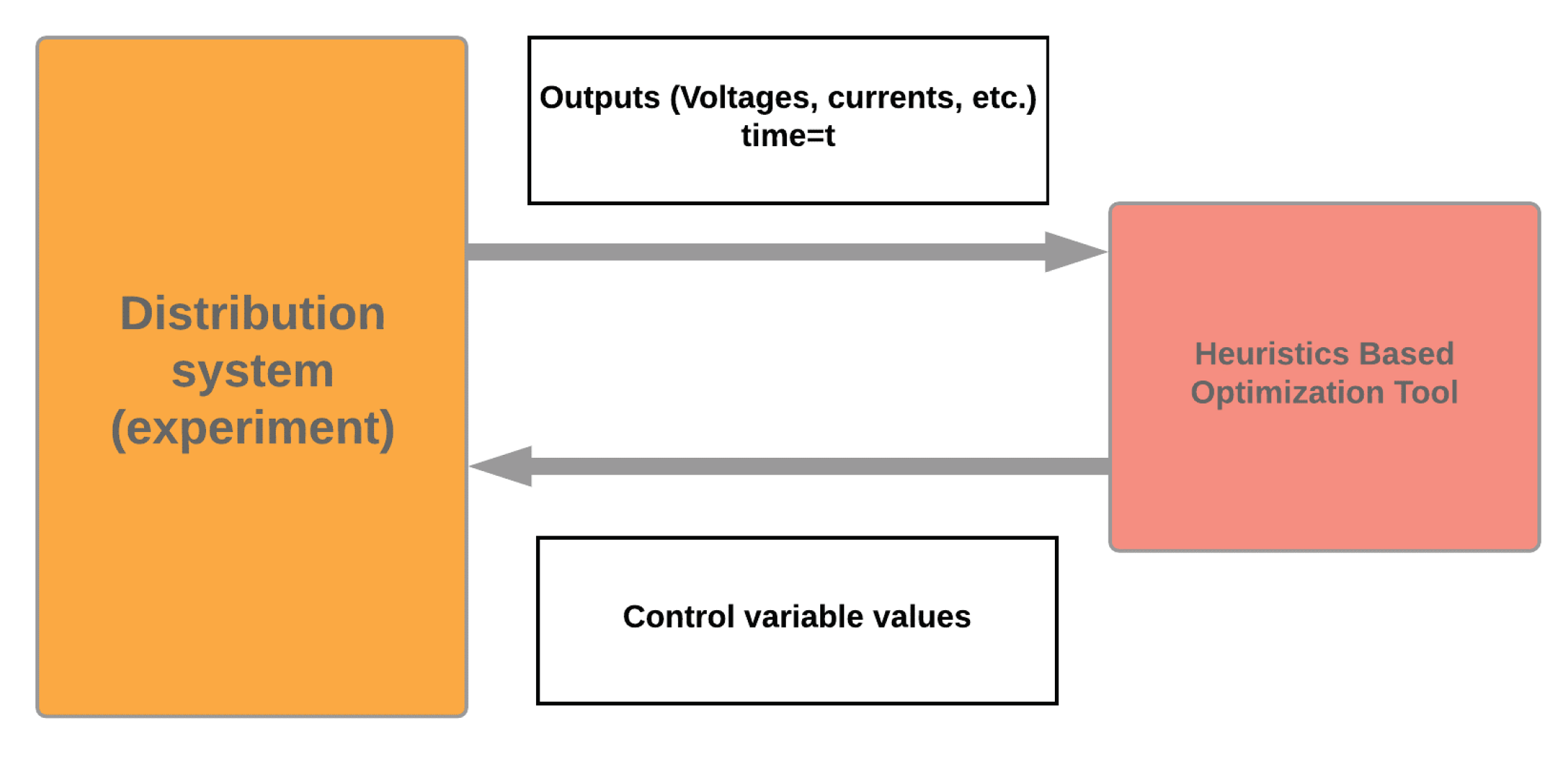
The experiment(s) and the simulation(s) are performed by using a coordinated approach as given in
Figure 1. From the figure, it is obvious that after an experiment is performed, several system parameters such as power flows, voltage magnitudes, phase angles can be transferred as parameters to the optimization tool. Harmony search based optimization tool then finds the optimal parameters to minimize the voltage deviations in the system and those parameters are then passed to the experimented system and the new parameter values are set.
2.2. Optimization Model
The study aims to minimize the negative impacts of the DERs in the system. This may be handled by minimizing the voltage deviations in the system. The optimization model aims to minimize the voltage deviation of all nodes with respect to a reference voltage node. We use the reference voltage as the voltage of the Point of Common Coupling (PCC) node:
Note that , and represent the active and reactive power outputs of the corresponding control device in the microgrid. The control devices used in this specific study are the active and reactive power outputs of the lithium-ion battery, Lead battery, NaNiCl Battery, Combined Heat and Power Generator (CHP) and controllable load.
The quantities, , , , , show the maximum active power output, minimum active power output, maximum reactive power output and minimum reactive power output of the controllable device respectively.
2.3. Ladder Iterative Technique
In this study a ladder iterative power flow approach is used to simulate the power flows both in grid connected and islanded mode operation cases. The technique consists of two main steps which are forward and backward sweeps. The method is briefly explained as follows.
The algorithm starts to work from the end nodes of the system and does the calculations based on Kirchoff Current and Voltage Laws up to the starting nodes. Then this computation order is reversed and computations are performed. The steps of the forward sweep are given as follows:
The voltage magnitudes at the end nodes are assumed to be same as the first node (see nodes
k and
l in
Figure 2).
Then the load currents at the end node(s) are calculated by using .
The current flows on the lines are calculated (
,
). Normally, these values are equal to the negative values of the currents on end nodes. However, for the junction nodes (see node
j in
Figure 2) this will be different: i.e.,
will be the arithmetic sum of
,
and the node current
using Kirchoff Current Law.
By using Kirchoff’s Voltage Law, the voltage on the next nodes are calculated (node i).
This computation procedure continues until the initial node. Then the actual voltage magnitude of the initial node is compared to that of the calculated one. If this value is smaller than a predefined tolerance, the algorithm stops otherwise the algorithm continues.
Perform the backward sweep calculations to compute the voltage magnitudes on the end nodes.
4. Tests and Numerical Results
The tests were performed implementing the harmony search based optimization algorithm on the low voltage Distributed Energy Resources Test Facility of RSE SpA [
27].
The test system is a three phase low voltage (400 V) microgrid interconnected to the MV grid by means of an 800 kVA dedicated transformer (23 kV/400 V) and has an overall capacity of 300 kW (active power) and 300 kVar (reactive power). Different types of energy storage systems (lithium-ion, lead-acid and high temperature Sodium-Nickel chloride batteries), loads and distributed energy resources (PV fields and CHPs) are connected.
The control acts on the active and reactive powers of the controllable devices, listed in
Table 1, in order to minimize the difference between the node’s voltage and the PCC’s voltage. To execute this control, the phase A power and the line-to-line voltage in each node were measured. During the test, the system was operating in balanced conditions, but actual control can be performed for unbalanced operating conditions, provided that, the battery systems can supply unbalanced power. The resolution of the simulation results provided in the following subsections are in seconds.
In grid connected tests, the PCC voltage is measured at the bus bar that the feeders are connected. The total reactance of the MV/LV transformer (leakage reactance) and the cable connecting the transformer the main bus, which is approximately the short circuit reactance, is approximately 0.02 ohms. The parameters of the components in the test system can be passed and the outputs may be monitored. Note that, unless otherwise stated, the limit values of the used control devices in the optimization process are as follows. Other devices are not used for controlling purposes, more details on the test system can be found in [
27].
We have conducted two different sets of tests: grid connected ones and the islanded operating mode tests.
4.1. Grid Connected Tests
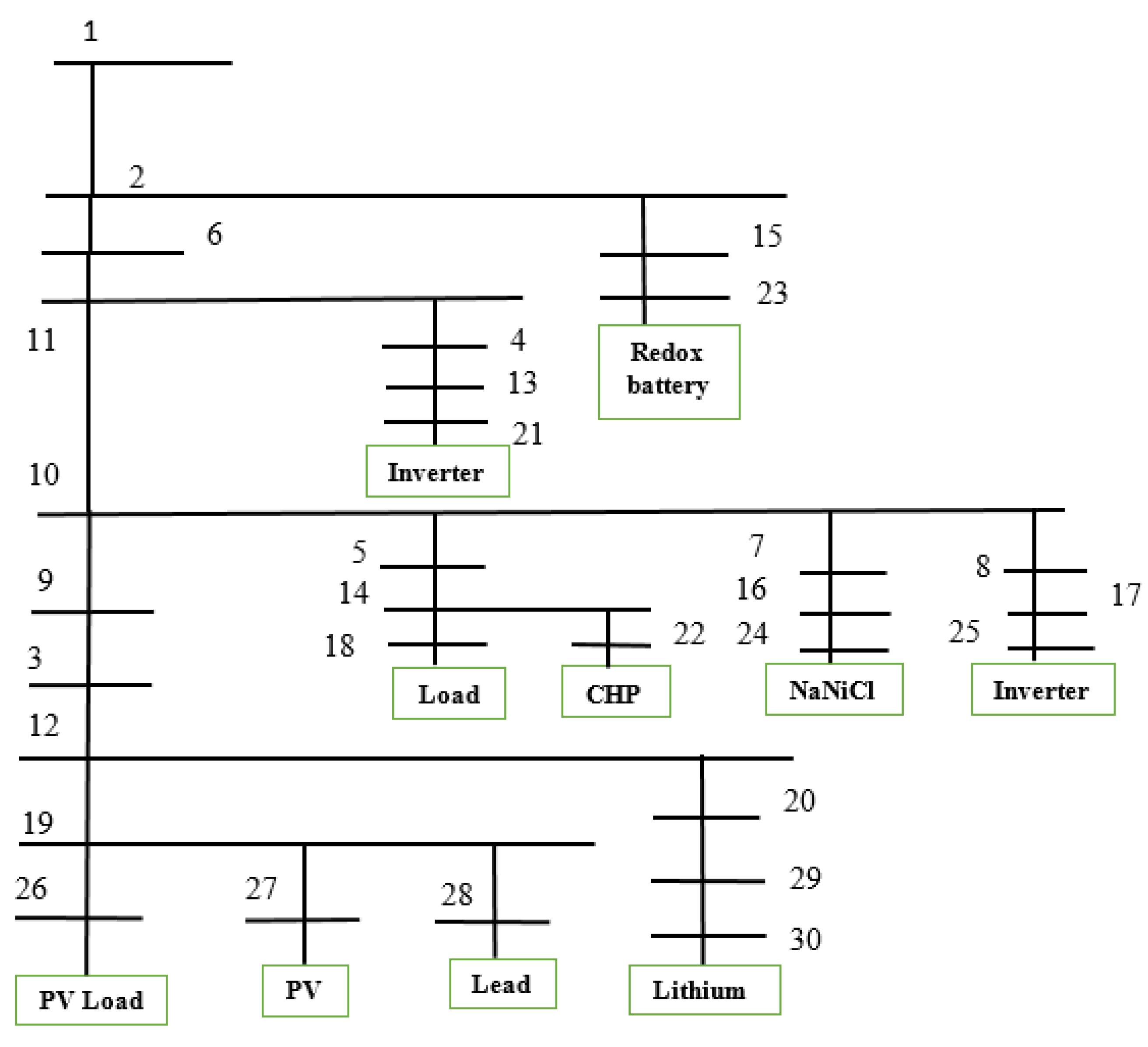
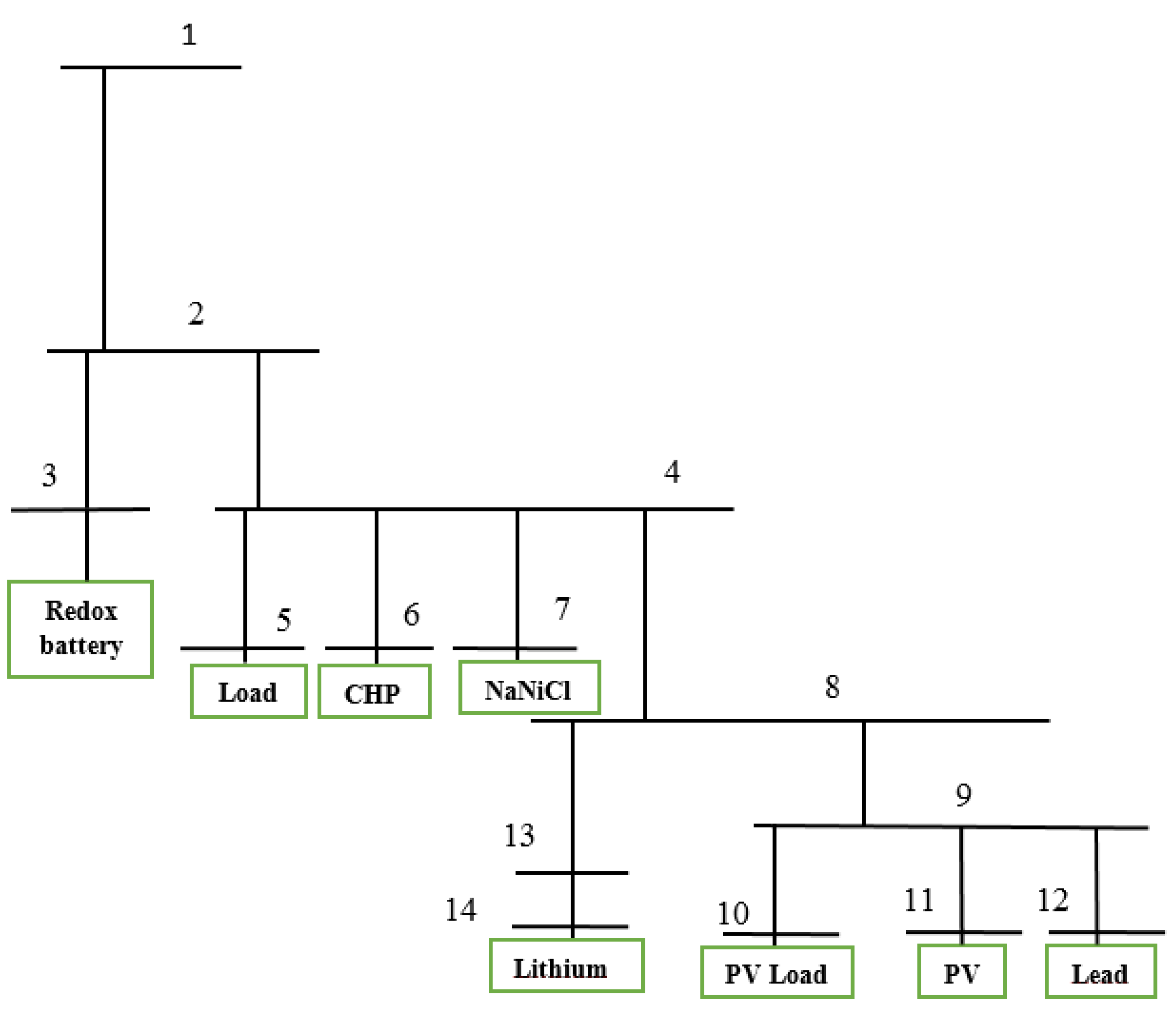
The first set of tests aim to simulate either cases with low voltage magnitudes, or with high voltages and aims to mitigate the negative impacts. Single line diagram of the grid connected test case drawn is given in
Figure 3. The line parameters are provided in
Appendix A.
In the first test, the initial status are chosen in order to analyze the behavior of the developed control to manage the undervoltage condition in the microgrid. In particular the initial values for the controllable components are given in
Table 2.
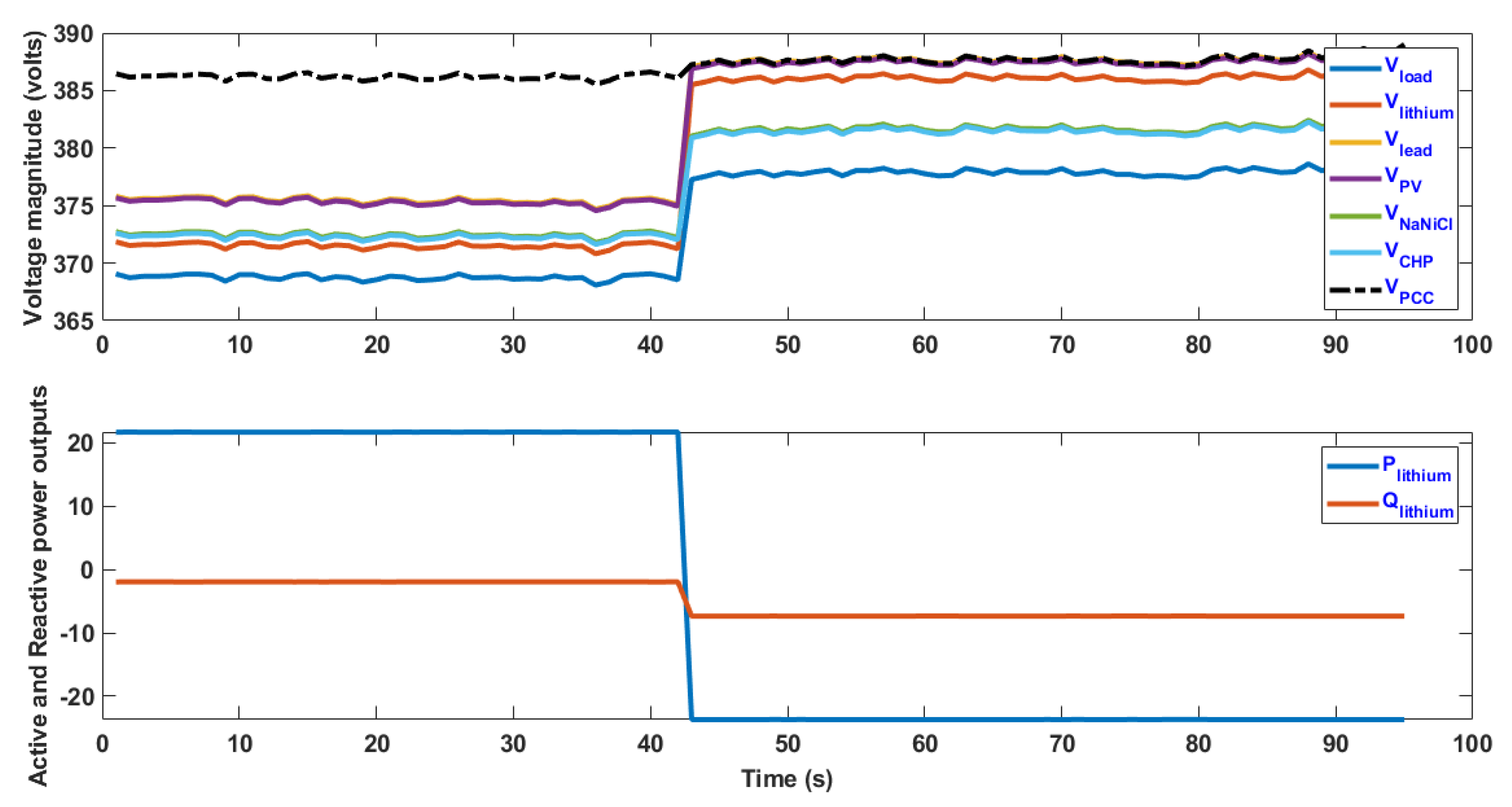
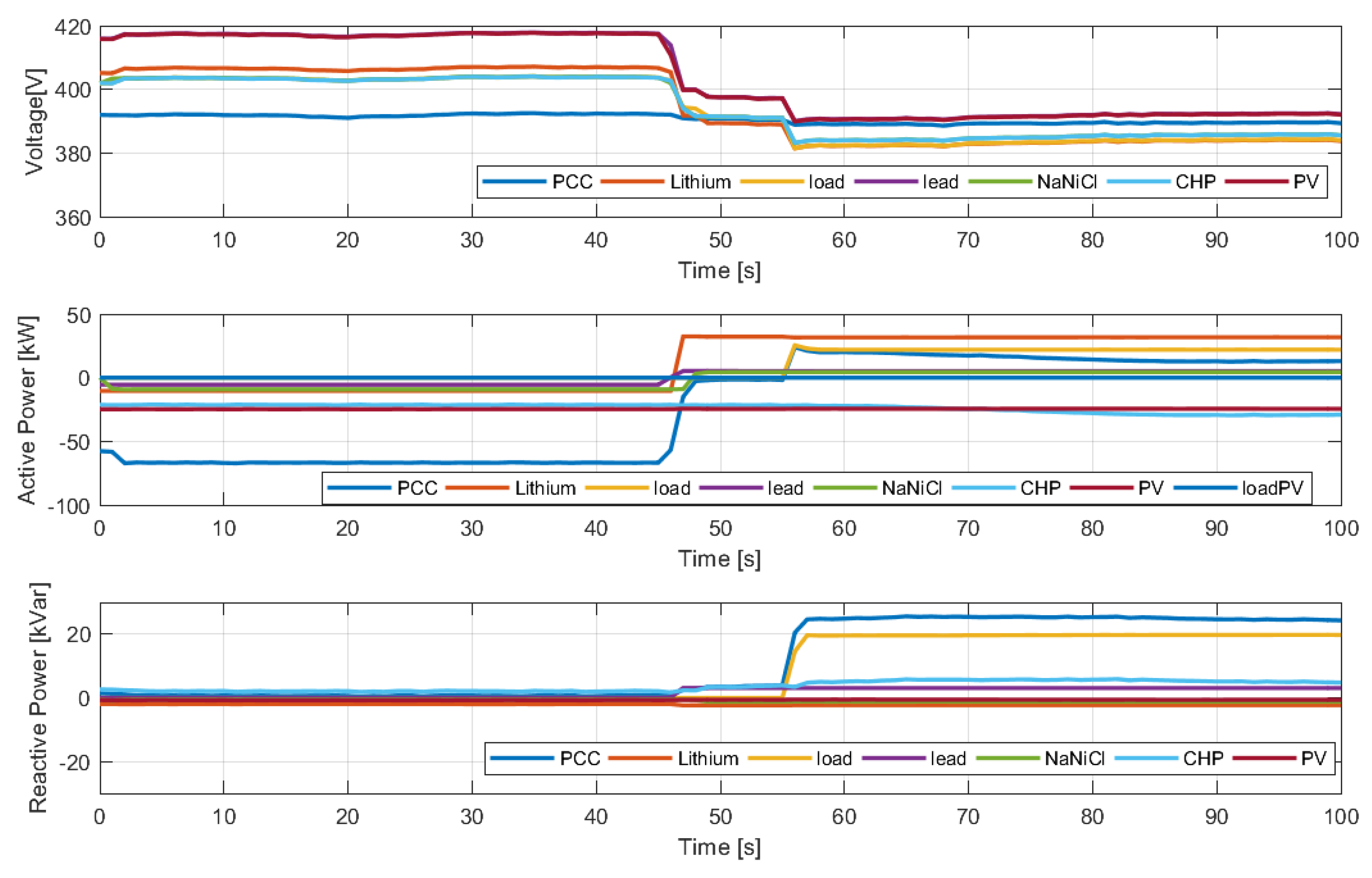
Under these initial conditions, voltage magnitudes of the PCC’s node (reference node) and of the other components of the microgrid are shown in the upper part of the
Figure 4. One may easily observe that the voltage magnitudes are lower compared with the PCC’s voltage and need to be increased. For this aim, lithium-ion battery inputs (both active and reactive powers) were controlled and as shown in the figure around the 45th second. The control allows the detection of near optimal values for the active and reactive power outputs that realize a better voltage profile. Note that in the initial condition lithium-ion battery was absorbing active power and supporting a small amount of reactive power, after the control operation is performed it is obvious that a better voltage profile is obtained.
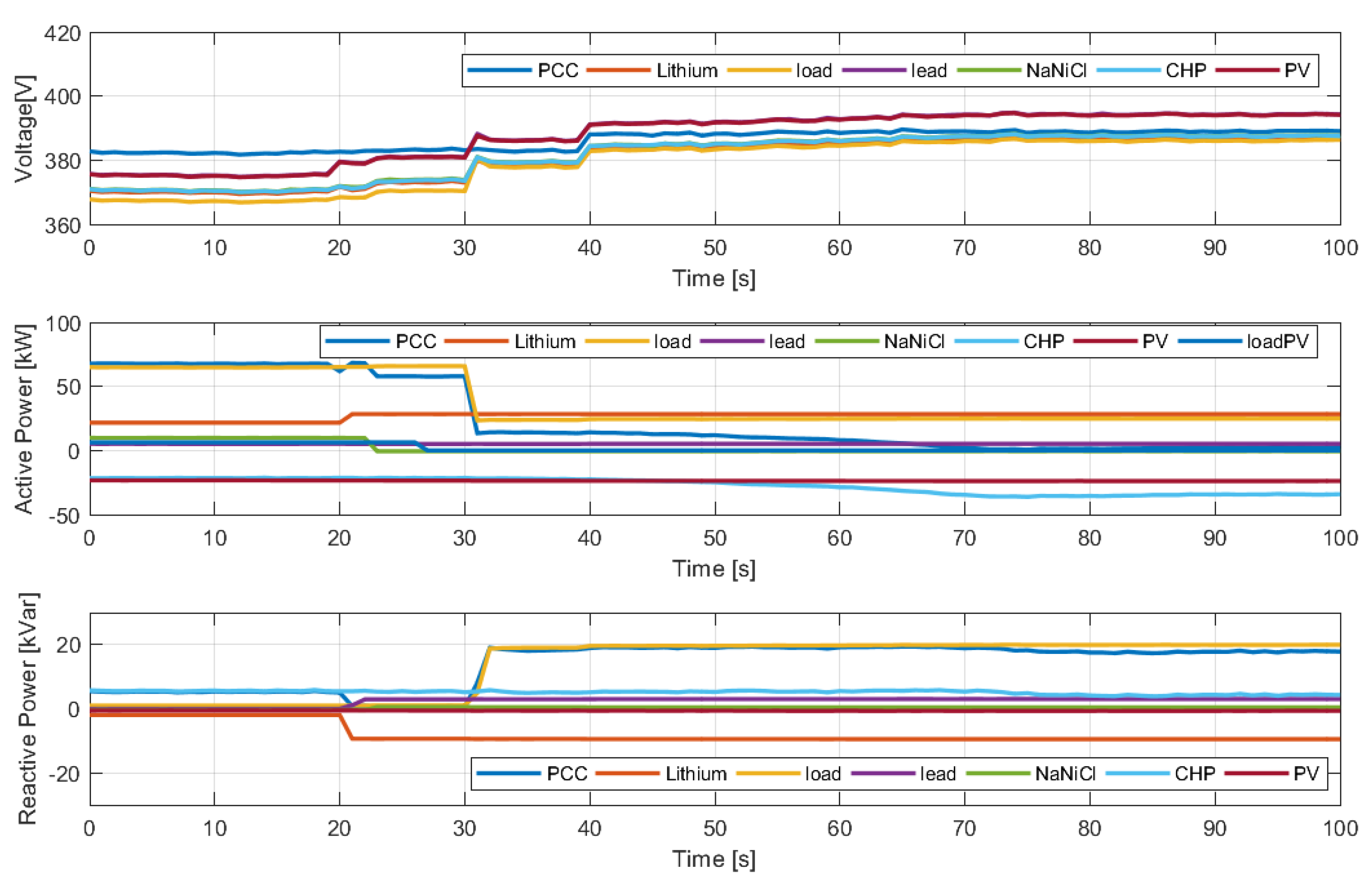
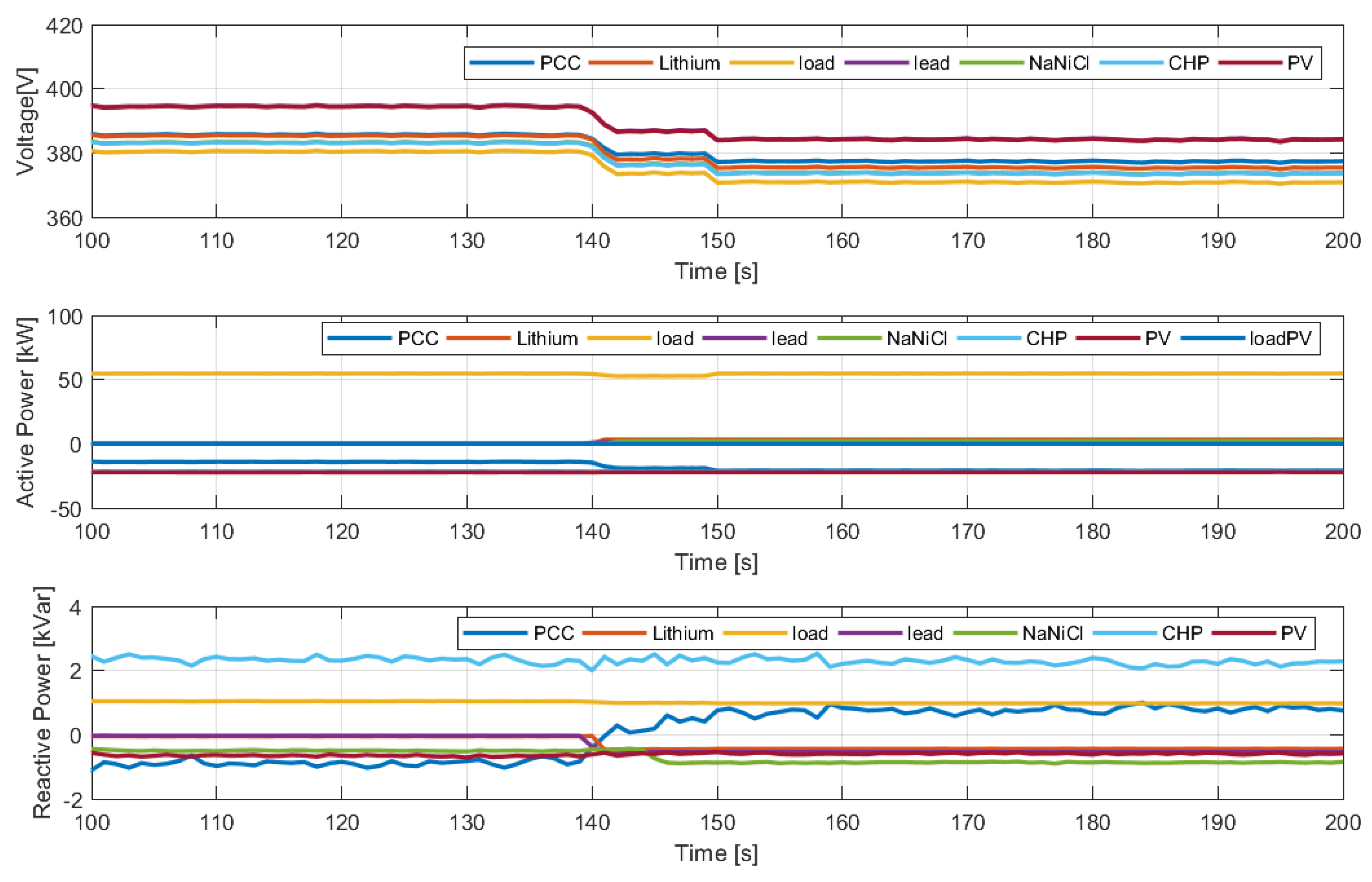
Considering the same conditions, a further test was performed taking into account the control of all the controllable resources. In
Figure 5 the related results are shown. It is worth noting that resorting to all the controllable resources it is possible to reduce again the gap between the PCC’s voltage and the other node’s voltage in the microgrid.
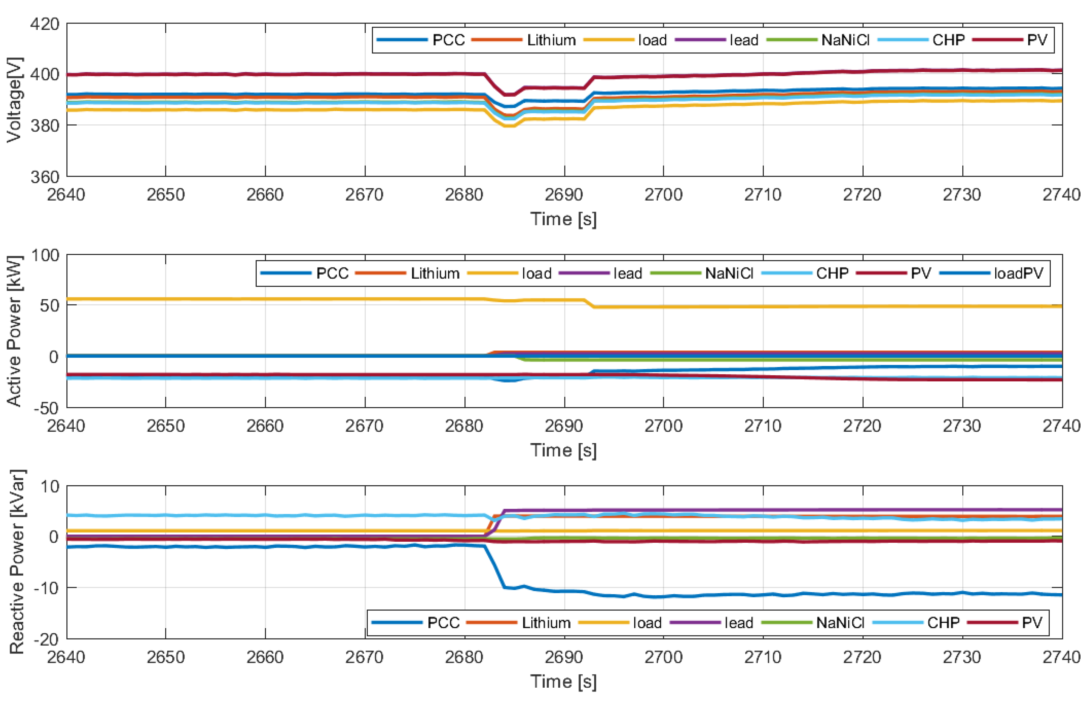
The second test was performed to observe the behavior during an overvoltage. For this aim the initial load values were set to 0 and as expected the voltage magnitudes in the system increased. The power values of Lead and NaNiCl batteries and the active loads on PV are controlled. Initial settings for this test case are given in
Table 3.
Under these initial conditions, voltage magnitudes of several components are shown in
Figure 6. Opposite to the previous test case, the voltage magnitudes are high and need to be lowered. This test case optimizes all the controllable resources in terms of active and reactive power. Around the 45th second, the control operation is applied and may be easily seen from the figure most of the components starts to charge themselves, and hence the voltage magnitudes in the system decrease and the gap between the PCC’s voltage and the other node’s voltage in the microgrid is reduced.
4.2. Islanded Operating Mode Tests
A second group of tests were performed to control the voltage magnitudes in islanded operating mode. The single line diagram of the islanded operating mode test case is shown in
Figure 7.
In island mode, the inverter connected to node 1, is used has a Grid-forming converter with droop control [
28]. Several different tests are performed for this case, and the results of two of them are provided. The parameters set for the first grid disconnected test case are given in
Table 4.
For this case, droop control parameters were set considering a maximum voltage variation dVmax equal to 5%, R/Z = 1 and X/Z = 0. The active and reactive power outputs of the tested batteries and the voltage magnitude of the PV bus are given in
Figure 8.
The same test is repeated by also allowing reactive load power to be controlled. This test used different droop control parameters: dVmax = 1%, R/Z = 1/2 and X/Z = 1/2. Results are provided in
Figure 9.


