Article

Electrolytically Ionized Abrasive-Free CMP (EAF-CMP) for Copper

1
Department of Mechanical System Engineering, Tongmyong University, Busan 48520, Korea
2
Department of Mechanical Engineering, Dong-A University, Busan 49315, Korea
*
Author to whom correspondence should be addressed.
Appl. Sci. 2021, 11(16), 7232; https://doi.org/10.3390/app11167232
Submission received: 14 July 2021 / Revised: 29 July 2021 / Accepted: 1 August 2021 / Published: 5 August 2021
(This article belongs to the Special Issue Chemical Mechanical Polishing and Grinding)

Abstract

:
Chemical–mechanical polishing (CMP) is a planarization process that utilizes chemical reactions and mechanical material removal using abrasive particles. With the increasing integration of semiconductor devices, the CMP process is gaining increasing importance in semiconductor manufacturing. Abrasive-free CMP (AF-CMP) uses chemical solutions that do not contain abrasive particles to reduce scratches and improve planarization capabilities. However, because AF-CMP does not use abrasive particles for mechanical material removal, the material removal rate (MRR) is lower than that of conventional CMP methods. In this study, we attempted to improve the material removal efficiency of AF-CMP using electrolytic ionization of a chemical solution (electrolytically ionized abrasive-free CMP; EAF-CMP). EAF-CMP had a higher MRR than AF-CMP, possibly due to the high chemical reactivity and mechanical material removal of the former. In EAF-CMP, the addition of hydrogen peroxide (H2O2) and citric acid increased the MRR, while the addition of benzotriazole (BTA) lowered this rate. The results highlight the need for studies on diverse chemical solutions and material removal mechanisms in the future.

1. Introduction

Chemical–mechanical polishing (CMP) is a semiconductor manufacturing process applied to planarize highly integrated devices [1,2,3]. It uses both chemical reactions and mechanical material removal to planarize the surface of a semiconductor. Recently, the importance of CMP has been increasing with the rise of integration and diversity of devices. Copper (Cu) wires, which are widely used in semiconductor devices, are manufactured using a damascene technique that uses CMP [4,5,6]. The material removal in Cu CMP is known to be mostly affected by chemical reactions rather than mechanical material removal using abrasive particles [7,8]. A Cu CMP slurry contains abrasives, oxidizers, complexing agents, and corrosion inhibitors, which react chemically with Cu to create a chemically reacted layer on the surface of the Cu [9,10].
In a Cu CMP slurry, the oxidizer creates Cu ions by oxidizing the Cu surface [11,12]. The Cu ions combine with the complexing agent to form a Cu complex [13,14,15]. Corrosion inhibitors reduce the corrosion reaction in the trench at the wafer pattern, enabling global and local planarization [16,17,18].
Many researchers have studied the chemical composition of Cu CMP slurries from a chemical reaction perspective. Hydrogen peroxide (H2O2) is commonly used as an oxidizer in Cu CMP because of its high oxidization capability [19]. H2O2 generates Cu ions from the Cu surface via oxidation. Gorantla et al. [20] proposed citric acid (C6H8O7) as a complexing agent in H2O2-based Cu CMP slurry. Citric acid is also widely used for post-Cu CMP cleaning. Complexing agents, including citric acid, are known to combine with Cu ions generated by oxidizers to prevent Cu ions from being re-absorbed into the Cu surface or produce a Cu complex layer on the surface of the Cu. Jung et al. [21] reported that the wear resistance of the Cu complex layer, generated by citric acid and H2O2 in Cu CMP, decreased as the citric acid concentration increased, making it easier to remove mechanically. Benzotriazole (BTA) is the most common corrosion inhibitor in Cu CMP [22] techniques. The addition of BTA to the CMP slurry formed a Cu-BTA complex layer to prevent excessive dissolution of the copper [23].
The abrasive serves to mechanically remove material from the interface of the wafer and the polishing pad, ensuring a high material removal rate (MRR) during CMP [24,25]. The common abrasives for Cu CMP are silica (SiO2) and alumina (Al2O3), and many researchers have studied Cu CMP results based on abrasive characteristics.
Wei et al. [26] investigated the influence of abrasive size in Cu CMP. They stated that in a Cu CMP slurry, if the particle size is small, then the particle concentration should be high. Hong et al. [27] studied the frictional behavior during Cu CMP by understanding the particle adhesion characteristics. They expressed that in a Cu CMP slurry, silica particles have a higher adhesion force, a higher friction force, and a higher MRR with Cu compared to alumina particles. According to Lee et al. [24], the friction force tends to increase as the colloidal silica concentration increases. High particle concentrations have been reported to help increase the MRR in CMP. However, abrasive particles can also be a scratch-inducing source instead of guaranteeing a high MRR [28]. In particular, a high particle concentration and agglomerated particles are the main factors that cause scratches during CMP. For this reason, several researchers have proposed the study of an abrasive–free CMP solution.
Pandija et al. [29] proposed an abrasive-free solution for Cu CMP using oxalic acid (C2H2O4) and H2O2. The adjustment of H2O2 concentration is efficient in controlling the MRR of Cu removed with an abrasive-free CMP (AF-CMP) solution. They observed the MRR to be the highest when the solution’s pH was 3. According to Ramakrishnan et al. [30], dicarboxylic acids, such as oxalic acid and malonic acid, can be used for abrasive-free CMP solutions under acidic conditions. Denardis et al. [31] studied the tribological characteristics of an abrasive–free solution for Cu. The use of an abrasive-free solution can help reduce dishing, erosion, and oxide loss during Cu CMP [32,33]. The advantages of the abrasive-free solution are as follows [34]:
(1)
Effortless maintenance of particle dispersion stability;
(2)
Continuous mixing in a slurry tank and filtration are not required;
(3)
Maintenance of the flow velocity of the slurry to prevent particle agglomeration is not necessary.
The abrasive-free CMP solution has a high concentration of toxic chemicals to compensate for the low MRR. Recently, a method using electrochemical ionization of slurry was introduced to improve the MRR in CMP. Lee et al. [35] proposed a Cu CMP method using an electrolytically ionized slurry to reduce slurry consumption. The slurry was ionized by attaching electrodes to the existing slurry nozzle and applying a voltage using a power supply (Figure 1). The electrolytically ionized slurry contains a high amount of –OH radicals, which activate the chemical reaction between the copper and the slurry. However, applying a voltage while the particles are dispersed within the slurry may cause particle agglomeration.
In this study, we investigated the use of electrolytically ionized abrasive-free CMP (EAF-CMP) to enhance the MRR of Cu. The abrasive-free CMP and the proposed electrolytically ionized abrasive-free CMP were compared in terms of electrochemical analysis and MRR. The effects of the oxidizer (H2O2), complexing agent (citric acid), and corrosion inhibitor (BTA) concentrations in the electrolytically ionized CMP solution were examined.

2. Experimental Setup

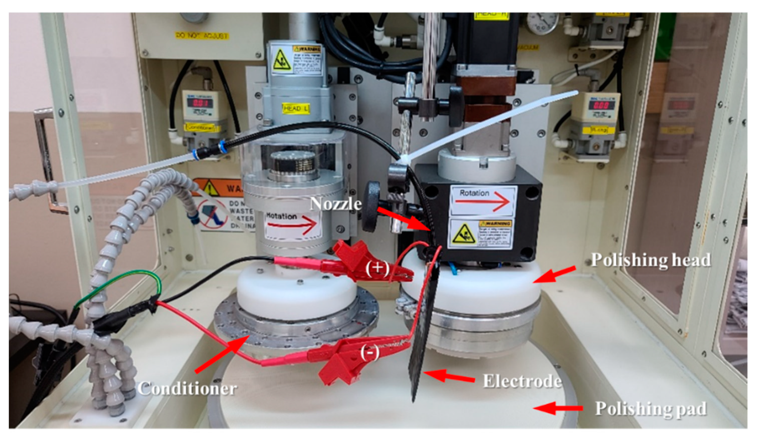
2.1. Electrolytic Ionization of CMP Solution and CMP Machine

For the experiment, a nozzle with electrodes was installed in the R&D CMP system (POLI-400, GnP technology Inc., Busan, Korea). The chemical solution from the nozzle passed through the electrodes and was supplied to the polishing pad. The voltage applied to the electrodes was regulated by an AC power supply (APS-7100E(CE), GW Instek, New Taipei City, Taiwan). The dimensions of the stainless steel electrode were 45 × 150 × 0.3 mm.
The diameter of the platen of the R&D CMP system is 406 mm and the wafer can be pressed through a pneumatic cylinder from 6.86 kPa (70 g/cm2) to 49.03 kPa (500 g/cm2). The rotation speed of the CMP machine varied from 30 to 200 rpm. Figure 2 shows the electrolytically ionized CMP system used in the experiment.

2.2. Experimental Conditions

The abrasive-free solution prepared for the experiments contained H2O2, citric acid, and BTA as oxidizers, complexing agents, and corrosion inhibitors, respectively. The prepared abrasive-free CMP solution was fixed at a pH of 3. Cu wafers 100 mm in diameter (Cu film thickness: 1.5 μm) were used. The rotational speeds of the platen and head were 80 rpm, and the applied pressure on the wafer and retaining ring were 29.4 and 39.2 kPa, respectively. The slurry flow rate was 150 mL/min. The voltage applied to the electrodes was fixed at 30 V. The CMP experiment was performed for 1 min per wafer with in situ conditioning. Table 1 lists the detailed conditions of the CMP experiments.
Before studying the electrolytically ionized abrasive-free solution, a basic experiment on an abrasive-free solution was conducted. A potentiostat with a working electrode (WE), counter electrode (CE), and reference electrode (RE) was used to analyze the electrochemical reaction between the solution and the Cu. The WE was connected to the Cu plate, the CE was a graphite rod, and the RE was a saturated calomel electrode (SCE). The equivalent weight and density of the Cu were 63.54 g/eq and 8.96 g/cm3, respectively. The circular exposed area between the sample and the solution was 7.79 cm2. Potentiodynamic polarization curves were obtained in the range of −1.5 V to 3.0 V with a scanning rate of 5 mV/s.
The thickness change of the Cu film after CMP was measured using a 4-point probe (CMT-SR200N, Changmin Tech Co., Ltd., Sungnam, Korea). The Cu film thickness was measured by a total of 21 points at 5 mm intervals in the diameter direction of the wafer. The edge exclusion in the thickness measurement was 3 mm. The calculation of MRR and within-wafer non-uniformity (WIWNU) followed the expressions below.
MRR = I n i t i a l   t h i c k n e s s F i n a l   t h i c k n e s s C M P   t i m e   ( nm / min )
WIWNU = S t a n d a r d   d e v i a t i o n   o f   M R R s A v e r a g e   v a l u e   o f   M R R s × 100   ( % )

3. Results and Discussion

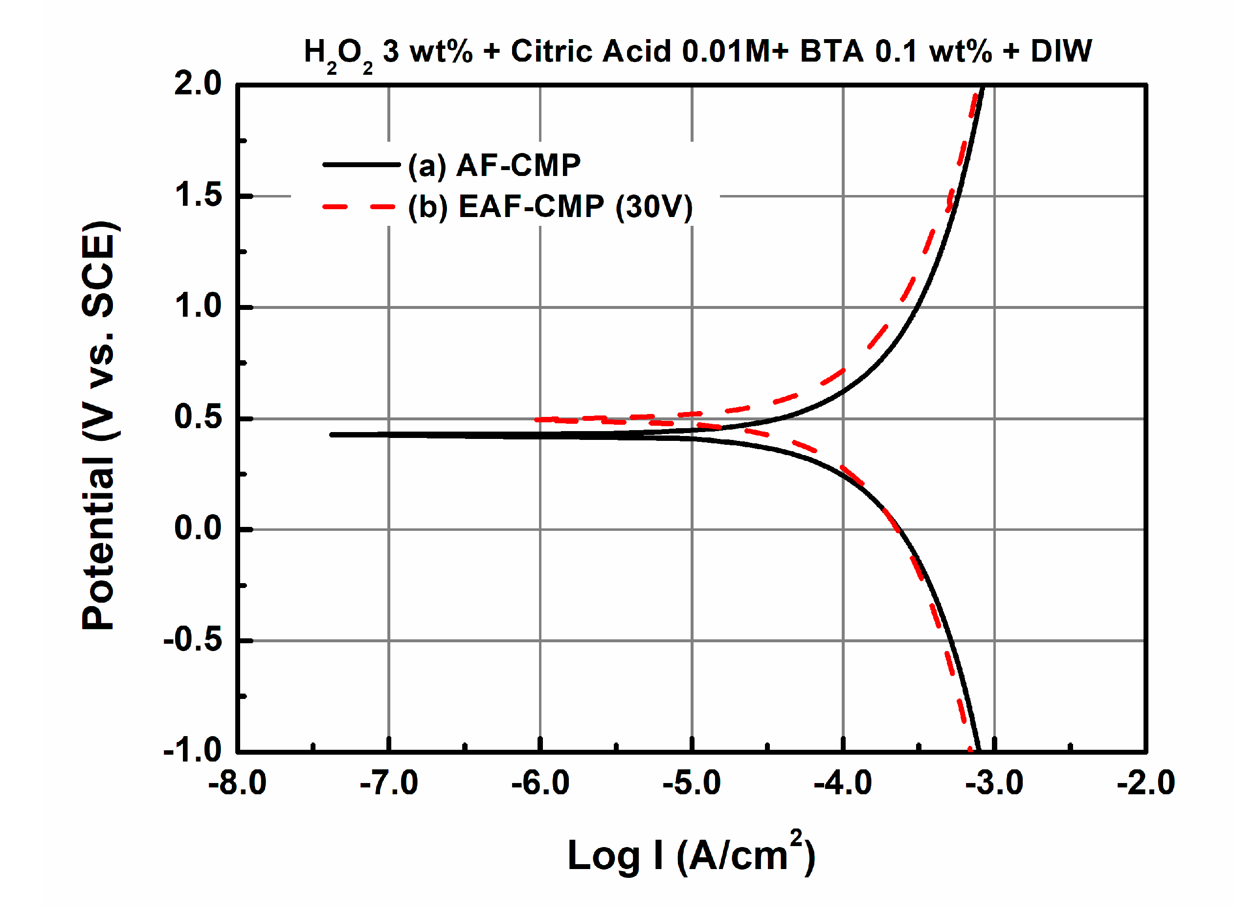
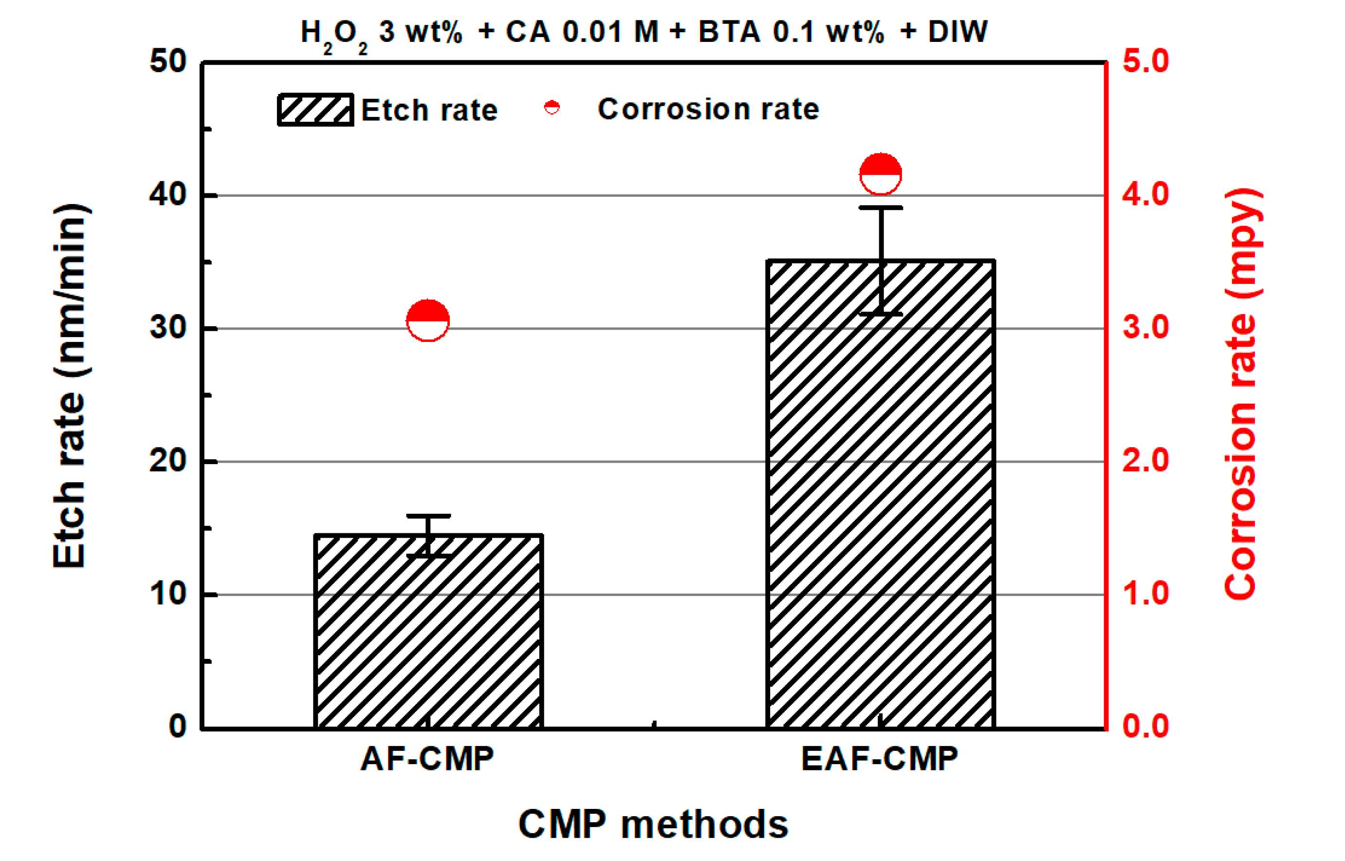
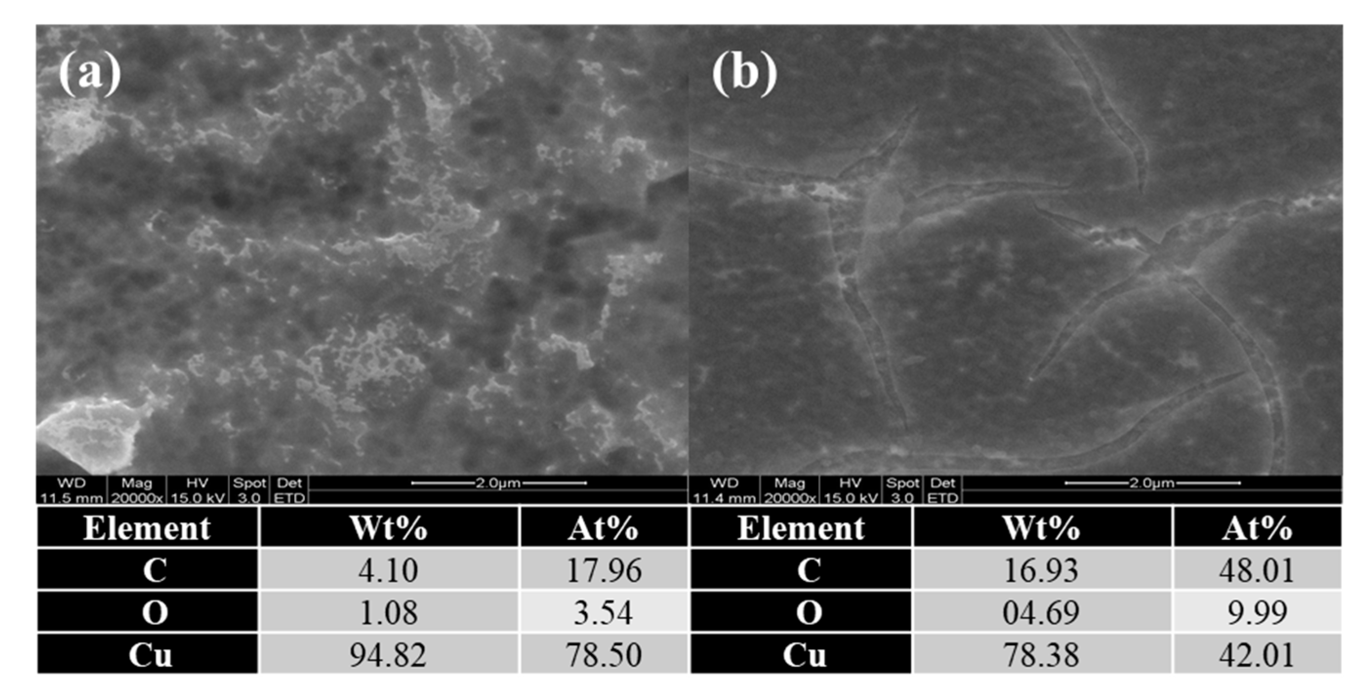
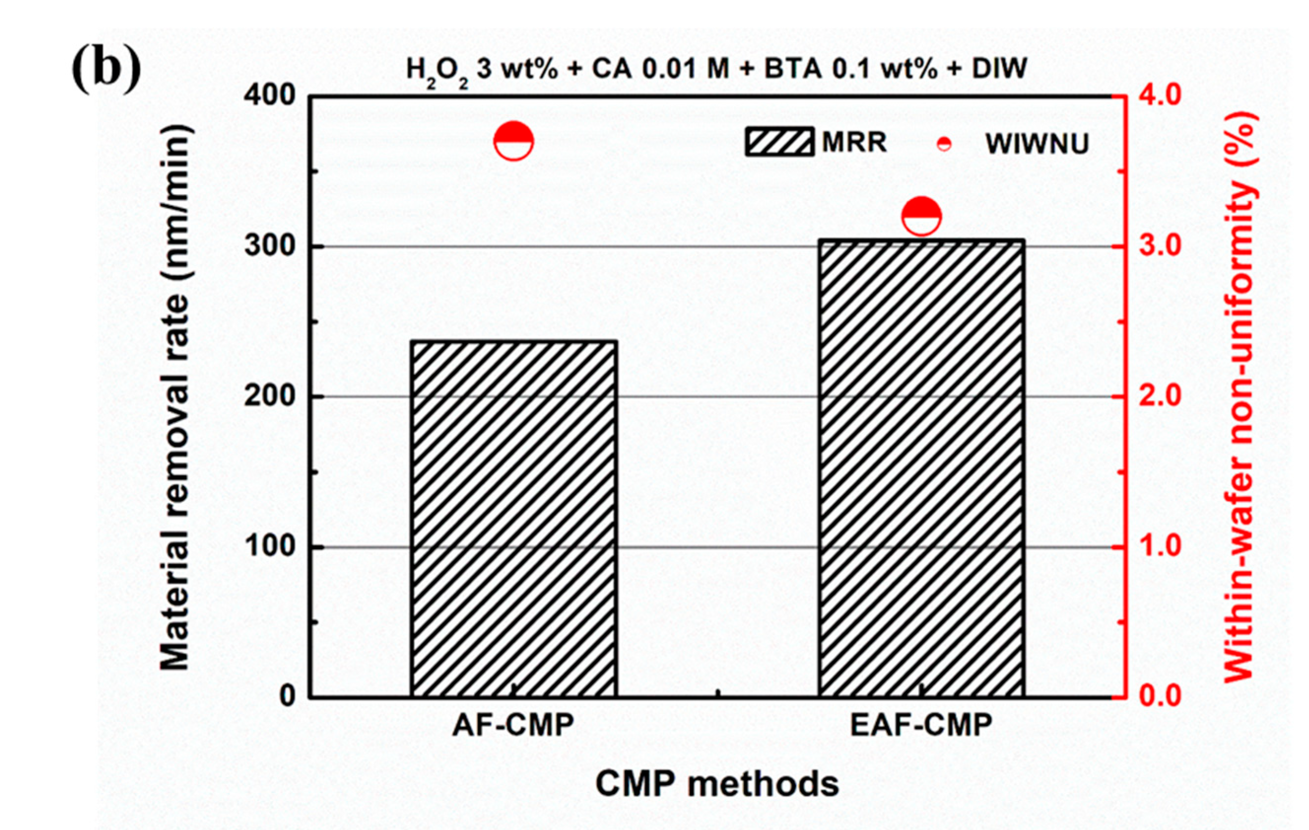
3.1. Comparison of AF-CMP and EAF-CMP

The potentiodynamic polarization curve provides information on the oxidation and reduction reactions. In Figure 3, the corrosion current density (ICorr) and corrosion rate (CR) were compared through polarization curves using a potentiostat to compare the electrolytically ionized CMP solution and general abrasive-free CMP solution. The prepared chemical solution consisted of 3 wt% H2O2, 0.01 M citric acid and 0.1 wt% BTA in deionized water (DIW). It has been reported that ICorr relates to the CR and material removal rate in CMP [36]. CR can be calculated as follows:
C R ( mpy ) = 0.13 × I c o r r × E w d ,
where Ew and d are the equivalent weight of the corroding species and the density of the corroding species, respectively.
In Figure 3, the ICorr of the non-ionized chemical solution was 3.35 μA/cm2 and the CR was 3.06 mils per year (mpy). If an AC voltage of 30 V was applied to the chemical solution through stainless steel electrodes, ICorr increased to 4.56 μA/cm2, and the CR to 4.16 mpy. According to Lee [35], CMP slurry ionization increased the number of –OH radicals in the CMP slurry, which improved the MRR in Cu CMP. In particular, H2O2, used as an oxidizer in Cu CMP slurry, is known to increase the oxidizing capacity by activating the generation of –OH radicals during ionization [35].
Figure 4 indicates that the static etch rate and CR of EAF-CMP were larger than those of AF-CMP. The etch rate was obtained by dipping 20 mm × 20 mm Cu wafers into chemical solutions for two minutes and measuring the thickness change of the Cu films. In the etching experiment, the chemical solution for EAF-CMP was electrolytically ionized by applying a 30 V voltage via electrodes to the chemical solution for the AF-CMP. The static etch rate was measured at five points (the center of the specimen and top, bottom, left, and right from the center of the specimen with a 5 mm span). The etch rates of AF-CMP and EAF-CMP were 14.5 nm/min and 35.1 nm/min, respectively.
Figure 5 shows the scanning electron microscopy (SEM) images and EDS analysis results of the Cu surfaces after dipping them into chemical solutions. Copper reacted with electrolytically ionized CMP solutions appears to have had more surface oxidation reactions than the copper reacted with abrasive-free CMP solutions.
Figure 6 shows the CMP results for AF-CMP and EAF-CMP. The detailed experimental conditions are listed in Table 1. The MRRs of AF-CMP and EAF-CMP were 236.9 nm/min and 303.9 nm/min, respectively. The within-wafer non-uniformity (WIWNU) of EAF-CMP was lower than that of AF-CMP. In AF-CMP, friction forces tended to decrease slightly over the processing time, with an average friction force of 5.509 kgf (Figure 7). In contrast, EAF-CMP showed a friction force similar to AF-CMP for the first 15 s of the process, but the friction force increased after 15 s. The increase in friction force during CMP may be due to the activation of the chemical reaction between the electrolytically ionized chemical solution and the Cu, which takes more than 15 s. The average frictional force in EAF-CMP was 7.946 kgf. The increase in friction force in EAF-CMP seems to be caused by the electrolytic ionization of the chemical solution, which increases the production of chemically reacted layers on the Cu surface. The results in Figure 3, Figure 4, Figure 5, Figure 6 and Figure 7 show that for EAF-CMP, the chemical reaction of the chemical solution and the copper is activated by electrolytic ionization of the slurry, resulting in a higher MRR and friction force compared to AF-CMP. Table 2 shows the comparison results between AF-CMP and EAF-CMP in this study.

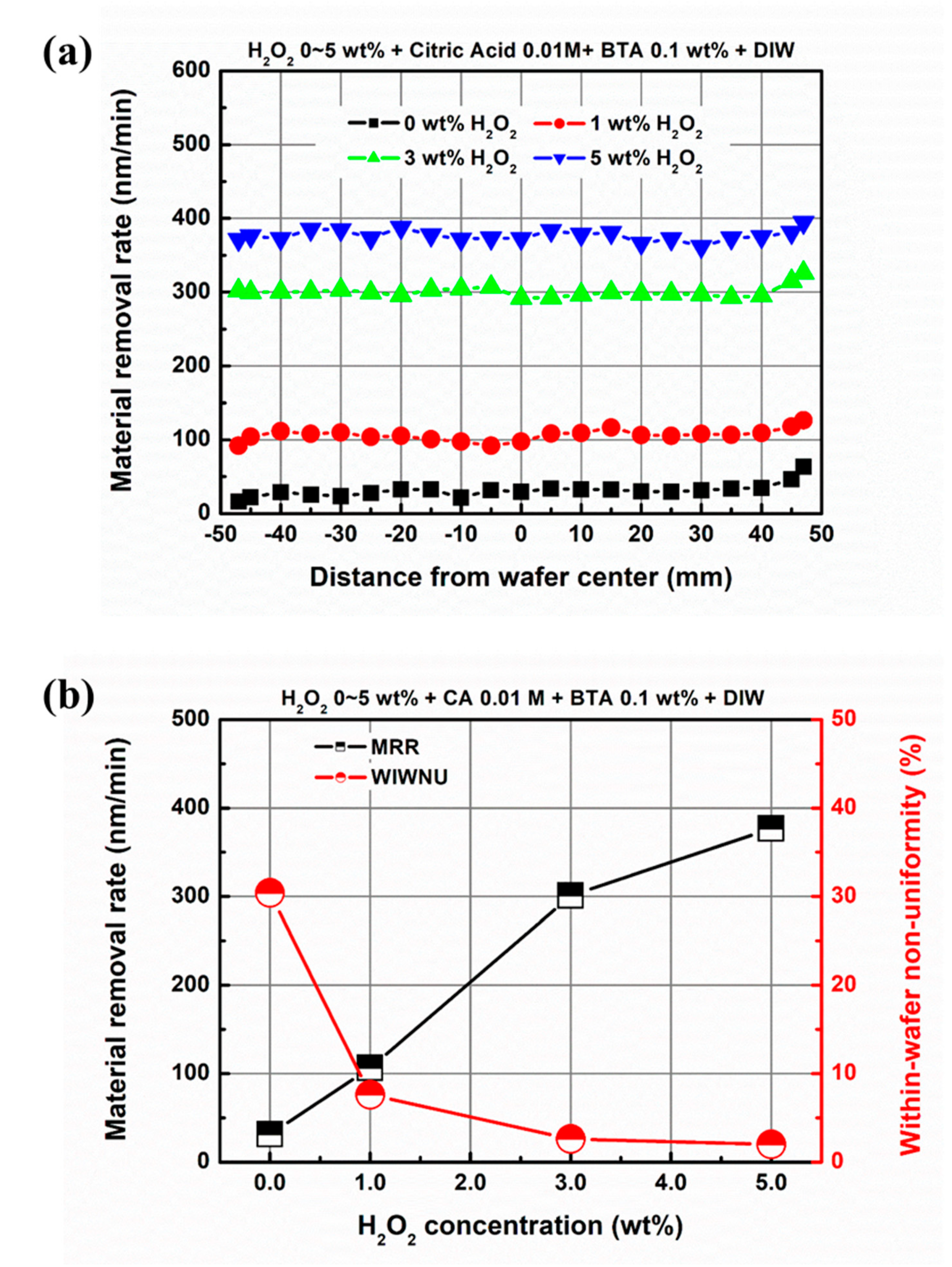
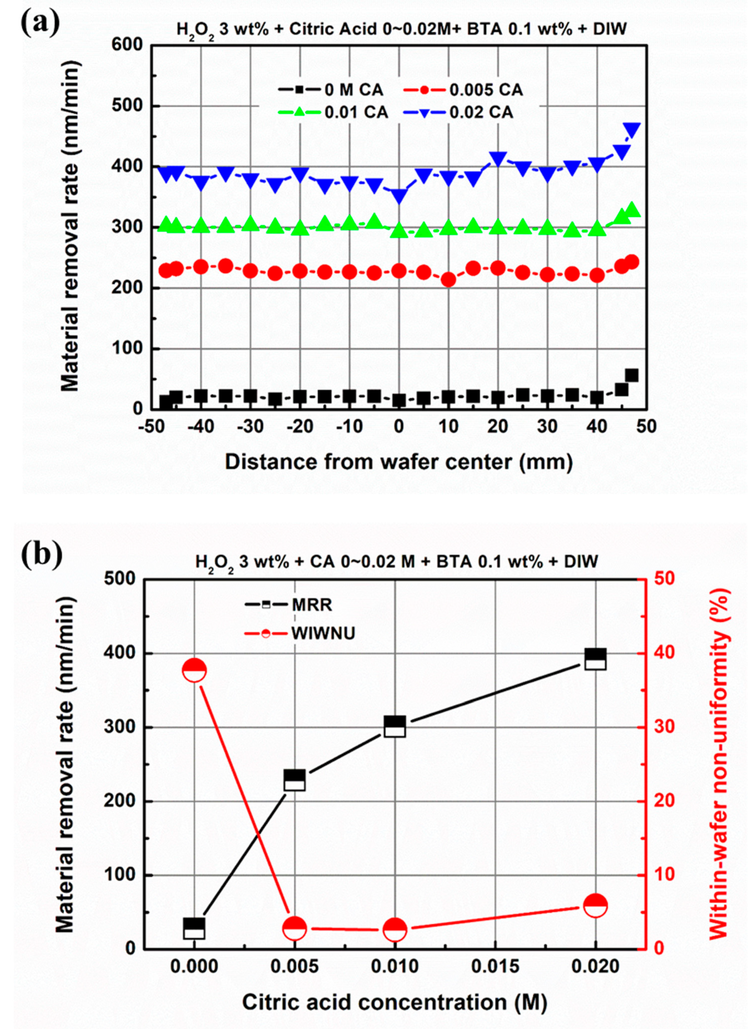
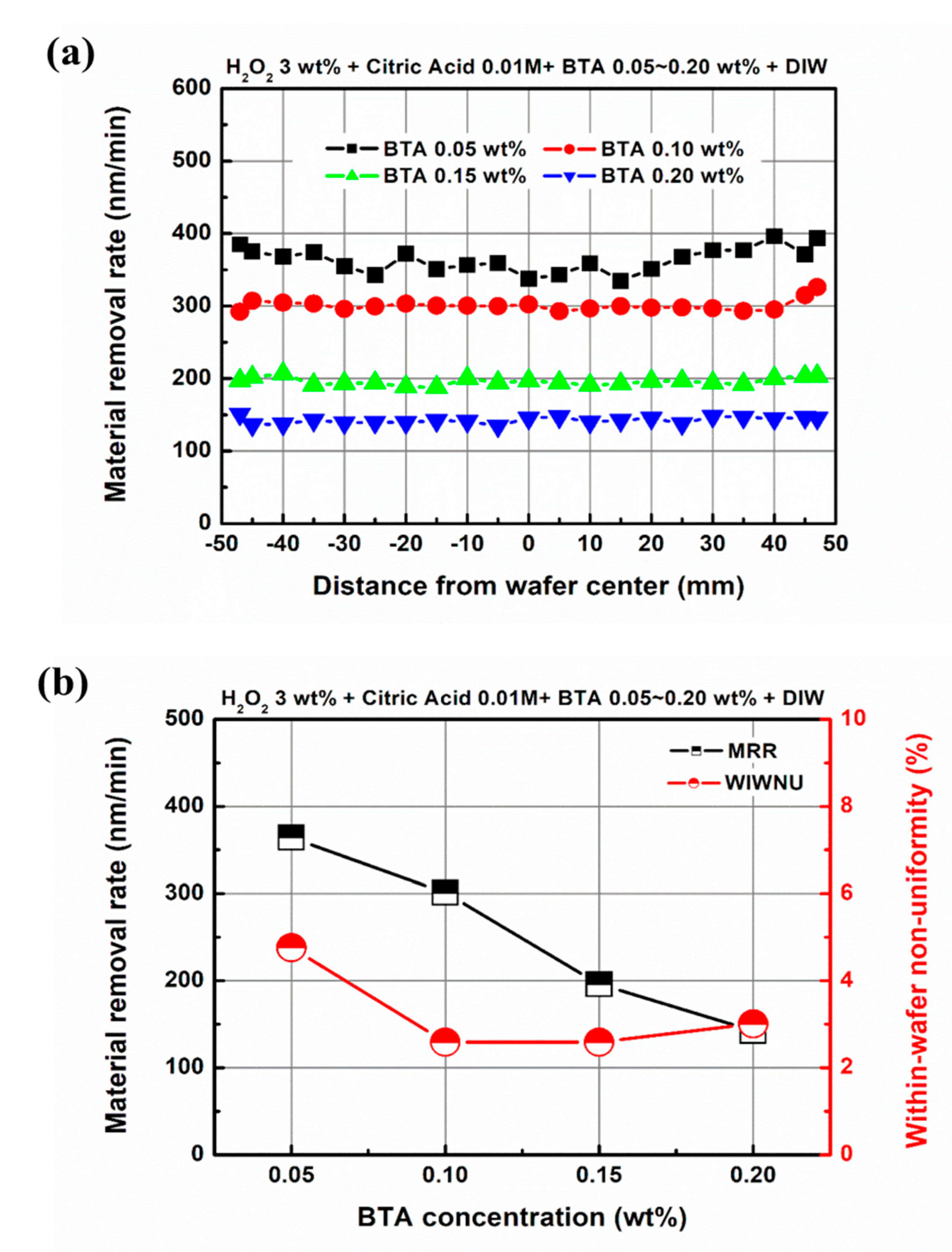
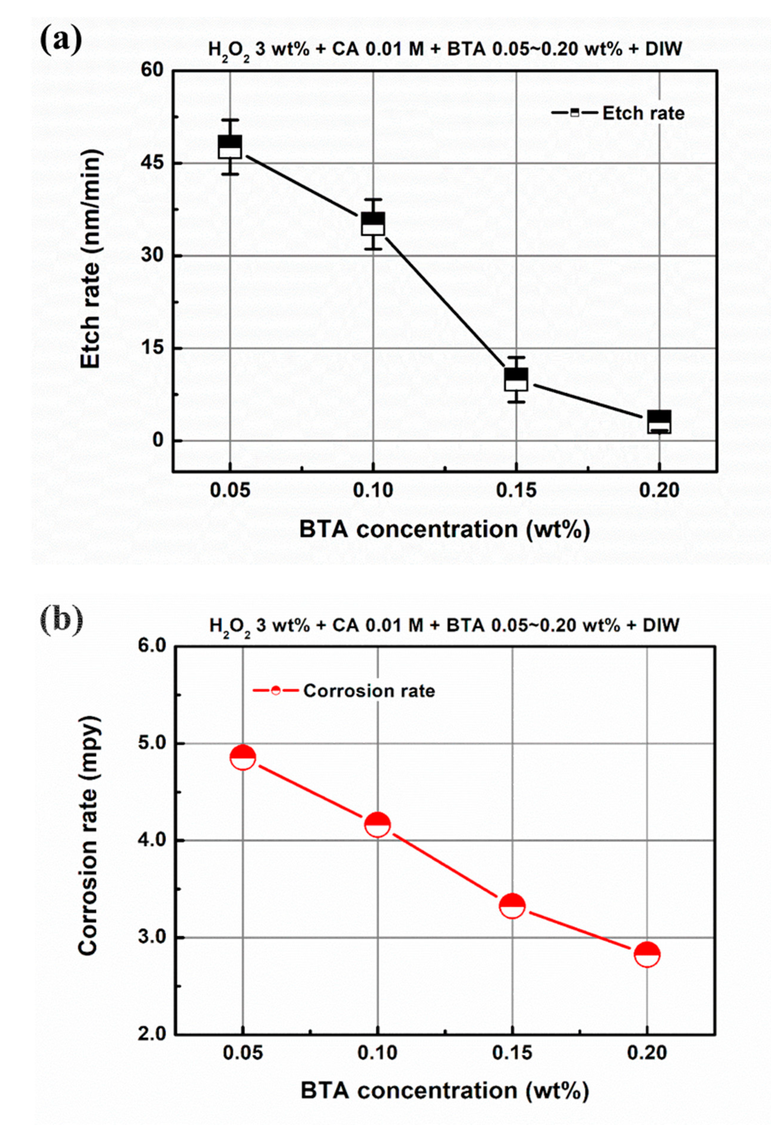
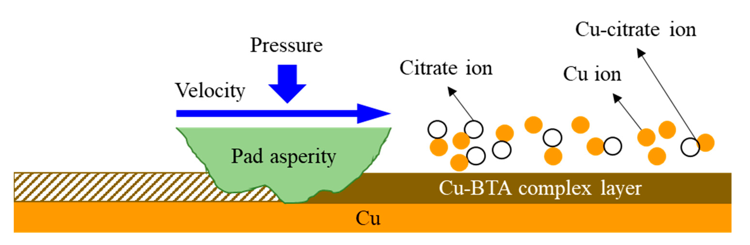
3.2. Effect of Chemical Component Concentration on Material Removal in EAF-CMP

In this section, the effects of the components of the EAF-CMP chemical solution on the MRR and WIWNU of Cu will be discussed. As mentioned in Section 2.2, the chemical solution for EAF-CMP contains H2O2, citric acid, and BTA as oxidizers, complexing agents, and corrosion inhibitors, respectively.
Figure 8 shows the MRR distribution (Figure 8a), average MRR, and WIWNU (Figure 8b) of Cu as a function of H2O2 concentration in the chemical solution. To determine the effect of changes in the H2O2 concentration on the MRR, the citric acid and BTA concentration were fixed at 0.01 M and 0.1 wt%, and the H2O2 concentration varied from 0 wt% to 5 wt%. Without H2O2 in the chemical solution, the average MRR was 31.4 nm/min and WIWNU was 30.4%. The average MRR continued to rise until the H2O2 concentration was increased to 5 wt%, and the average MRR improved to 303.9 nm/min and WIWNU to 3.2%. In Cu CMP, H2O2, used as an oxidizer, oxidized the surface of the Cu, helping to create a mechanically easy-to-remove surface [37,38]. Copper etching occurs when Cu ions and complexing agents are combined during the oxidation of Cu.
Figure 9a shows the changes in the etch rate of the Cu according to the H2O2 concentration. Without H2O2 in the chemical solution, the etch rate of the Cu was 5.6 nm/min. The etch rates at H2O2 concentrations of 1 wt%, 3 wt%, and 5 wt% were 24.8, 35.1, and 43.4 nm/min, respectively. Figure 9b shows that CR continued to increase from 0.31 mpy to 5.44 mpy as the H2O2 concentration increased from 0 wt% to 5 wt%. Thus, as the H2O2 concentration increased, the etch rate of the Cu increased because of the electrolytically ionized chemical solution, resulting in an increase in the MRR.
As shown in Figure 10, citric acid, which acts as a complexing agent in the Cu EAF-CMP, also increased the average MRR as its concentration in the chemical solution increased. During the experiment on the effect of citric acid, H2O2 concentration and BTA concentration were fixed at 3 wt% and 0.1 wt%, respectively, and the citric acid concentration was changed from 0 M to 0.02 M. As shown in Figure 10a, when the citric acid content was 0 M, the average MRR was 27.7 nm/min, and the addition of 0.005 M citric acid to the chemical solution greatly increased the average MRR to 288.4 nm/min. When the citric acid concentration in the chemical solution was 0.01 M and 0.02 M, the average MRR gradually increased to 300.9 and 391.6 nm/min. WIWNU decreased with the addition of citric acid, having the lowest value of 2.6% at 0.01 M, which slightly increased at 0.02 M to 5.9%. As in experiments with H2O2 concentration changes, the etch rate of Cu tends to increase with increasing citric acid concentration in electrolytically ionized chemical solutions.
As shown in Figure 11a, while citric acid concentration increased from 0 M to 0.02 M, the etch rate of the Cu increased from 3.0 nm/min to 83.5 nm/min. The CR also increased as the citric acid concentration increased (Figure 11b). When citric acid is 0 M in the chemical solution, the CR is 0.04 mpy, and when 0.02 M of citric acid is added, the CR increases dramatically to 5.44 mpy. The increased citric acid concentration in the chemical solutions of EAF-CMP appears to increase the probability of binding citric acid and Cu ions, increasing the etch rate and average MRR.
Corrosion inhibitors form a Cu complex film, which helps planarize patterns by controlling excessive corrosion by the oxidizer in the CMP slurry. Figure 12 shows the change in MRR and its distribution according to the BTA concentration. The average MRR tended to decrease as the BTA concentration of the chemical solution increased. The average MRR was 364.1, 300.9, 196.0, and 142.5 nm/min, respectively, when the chemical solution contained 0.05 wt%, 0.10 wt%, 0.15 wt%, and 0.20 wt% of BTA. Compared to the results of changes in H2O2 and citric acid concentration, the changes in the WIWNU were small, with the lowest being at 0.01 wt% and 0.15 wt%. As the BTA content increased, the CR and etch rate tended to decrease because the Cu-BTA complex layer inhibited the dissolution of the Cu by the chemical solution (Figure 13) [23].
In this study, a comparative study of AF-CMP and EAF-CMP was conducted, and it was confirmed that the MRR can be improved by the electrolytic ionization of chemical solutions for AF-CMP. Electrolytically ionized chemical solutions seem to produce a more mechanically easy-to-remove chemically reacted layer and higher chemical dissolution of Cu than conventional chemical solutions using AF-CMP. Figure 14 shows the probable material removal mechanism of EAF-CMP. The oxidation reaction of the electrolytically ionized chemical solution and the Cu generates Cu ions, which are combined with citrate ions in the chemical solution and removed from the surface of the Cu in the form of Cu–citrate ions. BTA in the chemical solution combines with the Cu ions to form a Cu-BTA complex layer on the surface of the Cu film and is removed by the asperities of the polishing pad, resulting in mechanical material removal. MRR increased with increases in concentrations of H2O2 and citric acid used as an oxidizer and complexing agent; however, MRR decreased with an increase in the concentration of BTA used as a corrosion inhibitor.
The proposed EAF-CMP in this study will be able to increase the efficiency of AF-CMP, and further research on chemical solution and material removal phenomena will be required. Furthermore, it seems that more diverse electrode materials and modularization of nozzle-containing electrodes are needed for a more efficient electrolytic ionization of the chemical solution.

4. Conclusions

In this paper, EAF-CMP using an electrolytically ionized chemical solution was proposed to improve the efficiency of AF-CMP. The EAF-CMP process seems to increase the MRR by activating chemical reactions with Cu through the electrolytic ionization of the chemical solution. EAF-CMP also showed a higher etch rate, CR, and friction force than the AF-CMP. The higher MRR of EAF-CMP than that of AF-CMP may be due to active chemical reactivity and mechanical material removal. In EAF-CMP, the MRR of Cu increased as the H2O2 and citric acid concentrations increased, but the MRR decreased as the BTA concentration increased. Changes in the MRR with the concentration of chemical components tended to be similar to changes in the etch rate and CR of Cu.
Electrolytic ionization of chemical solutions appears to be able to increase the material removal efficiency of AF-CMP, and research on chemical solutions of more diverse configurations and material removal mechanisms will be needed in the future.

Author Contributions

Conceptualization, S.P.; investigation, S.P. and H.L.; project administration, H.L.; supervision, H.L.; writing—original draft, S.P.; writing—review and editing, H.L.; funding acquisition, H.L. Both authors have read and agreed to the published version of the manuscript.

Funding

This research was supported by the BB21+ Project in 2021 and Basic Science Research Programs through the National Research Foundation of Korea (NRF) funded by the Ministry of Education (NRF-2018R1D1A1B07043169) and the Ministry of Science and ICT (NRF-2021R1F1A1063060).

Institutional Review Board Statement

Not applicable.

Informed Consent Statement

Not applicable.

Data Availability Statement

Data sharing is not applicable to this article.

Acknowledgments

We thank G&P Technology Inc. for the support for the experiment.

Conflicts of Interest

The authors declare no conflict of interest.

References

  1. Lee, H.; Lee, D.; Jeong, H. Mechanical aspects of the chemical mechanical polishing process: A review. Int. J. Precis. Eng. Manuf. 2016, 17, 525–536. [Google Scholar] [CrossRef]
  2. Lee, H.; Lee, S. Investigation of pad wear in CMP with swing-arm conditioning and uniformity of material removal. Precis. Eng. 2017, 49, 85–91. [Google Scholar] [CrossRef]
  3. Zhao, G.; Wei, Z.; Wang, W.; Feng, D.; Xu, A.; Liu, W.; Song, Z. Review on modeling and application of chemical mechanical polishing. Nanotechnol. Rev. 2020, 9, 182–189. [Google Scholar] [CrossRef] [Green Version]
  4. Hara, T.; Balakumar, S. Chemical mechanical polishing of copper layer employing MnO2 slurry. Thin Solid Films 2004, 462–463, 186–191. [Google Scholar] [CrossRef]
  5. Hu, C.-K.; Luther, B.; Kaufman, F.B.; Hummel, J.; Uzoh, C.; Pearson, D.J. Copper interconnect integration and reliability. Thin Solid Films 1995, 262, 84–92. [Google Scholar] [CrossRef]
  6. Wrschka, P.; Hernandez, J.; Oehrlein, g.S.; King, J. Chemical mechanical planarization of copper damascene structures. J. Electrochem. Soc. 2000, 147, 706–712. [Google Scholar] [CrossRef] [Green Version]
  7. Lee, H.; Jeong, H. A wafer-scale material removal rate profile model for copper chemical mechanical planarization. Int. J. Mach. Tools Manuf. 2011, 51, 395–403. [Google Scholar] [CrossRef]
  8. Lee, H.S.; Jeong, H.D. Chemical and mechanical balance in polishing of electronic materials for defect-free surfaces. CIRP Ann. Manuf. Technol. 2009, 58, 485–490. [Google Scholar] [CrossRef]
  9. Lee, D.; Lee, H.; Jeong, H. Slurry Components in Metal Chemical Mechanical Planarization (CMP) Process: A Review. Int. J. Precis. Eng. Manuf. 2016, 17, 1751–1762. [Google Scholar] [CrossRef]
  10. Lee, H. Environmental Impact of Concentration of Slurry Components in thick Copper CMP. Int. J. Precis. Eng. Manuf.-Green Tech. 2017, 4, 13–18. [Google Scholar] [CrossRef]
  11. Rui, X.; Yongsheng, W.; Yipu, W.; Haixu, L.; Jianxiu, S. Study on Oxidant in Chemical Mechanical Polishing of Copper. Trans. Electr. Electron. Mater. 2020, 21, 580–586. [Google Scholar] [CrossRef]
  12. Du, T.; Tamboli, D.; Desai, V. Electrochemical characterization of copper chemical mechanical polishing. Microelectron. Eng. 2003, 69, 1–9. [Google Scholar] [CrossRef]
  13. Gorantla, V.R.K.; Matijević, E.; Babu, S.V. Amino Acids as Complexing Agents in Chemical−Mechanical Planarization of Copper. Chem. Mater. 2005, 17, 2076–2080. [Google Scholar] [CrossRef]
  14. Jang, S.; Jeong, H.; Yuh, M.; Park, I.; Park, J. Effect of glycine on copper CMP. Int. J. Precis. Eng. Manuf.-Green Tech. 2016, 3, 155–159. [Google Scholar] [CrossRef]
  15. Kim, T.; Lee, H. Preliminary Study on fluidized Bed Chemical Mechanical Polishing (FB-CMP) Process for Stainless Steel 304 (SS304). Micromachines 2020, 11, 705. [Google Scholar] [CrossRef] [PubMed]
  16. Ryu, H.-Y.; Cho, B.-J.; Yerriboina, N.P.; Lee, C.-H.; Hwang, J.-K. Selection and Optimization of Corrosion Inhibitors for Improved Cu CMP and Post-Cu CMP Cleaning. ECS J. Solid State Sci. Technol. 2019, 8, P3058. [Google Scholar] [CrossRef]
  17. Deshpande, D.; Kuiry, S.C.; Klimov, M.; Obeng, Y.; Seal, S. Chemical mechanical planarization of copper: Role of oxidants and inhibitors. J. Electrochem. Soc. 2004, 151, G788–G800. [Google Scholar] [CrossRef]
  18. Du, T.; Luo, Y.; Desai, V. The combinatorial effect of complexing agent and inhibitor on chemical-mechanical planarization of copper. Microelectron. Eng. 2004, 71, 90–97. [Google Scholar] [CrossRef]
  19. Eom, D.-H.; Kim, I.-K.; Han, J.-H.; Park, J.-G. The Effect of Hydrogen Peroxide in a Citric Acid Based Copper Slurry on Cu Polishing. J. Electrochem. Soc. 2007, 154, D38–D44. [Google Scholar] [CrossRef]
  20. Gorantla, V.R.K.; Assiongbon, K.A.; Babu, S.V.; Roy, D. Citric Acid as a Complexing Agent in CMP of Copper: Investigation of Surface Reactions Using Impedance Spectroscopy. J. Electrochem. Soc. 2005, 152, G404–G410. [Google Scholar] [CrossRef]
  21. Jung, W.; Park, B.; Lee, H.; Jeong, H. Effects of Citric Acid as a Complexing Agent on Material Removal in Cu CMP. J. Korean Inst. Electr. Electron. Mater. Eng. 2006, 19, 889–893. [Google Scholar]
  22. Krishnan, M.; Nalaskowski, J.W.; Cook, L.M. Chemical Mechanical Planarization: Slurry Chemistry, Materials, and Mechanisms. Chem. Rev. 2010, 110, 178–205. [Google Scholar] [CrossRef]
  23. Cho, B.-J.; Shima, S.; Hamada, S.; Park, J.-G. Investigation of cu-BTA complex formation during Cu chemical mechanical planarization process. Appl. Surf. Sci. 2016, 384, 505–510. [Google Scholar] [CrossRef]
  24. Lee, H.; Joo, S.; Jeong, H. Mechanical Effect of colloidal silica in copper chemical mechanical planarization. J. Mater. Proc. Technol. 2009, 209, 6134–6139. [Google Scholar] [CrossRef]
  25. Lee, H.; Park, B.; Jeong, H. Mechanical effect of process condition and abrasive concentration on material removal rate profile in copper chemical mechanical planarization. J. Mater. Proc. Technol. 2009, 209, 1729–1735. [Google Scholar] [CrossRef]
  26. Wei, K.-H.; Wang, Y.-S.; Liu, C.-P.; Chen, K.-W.; Wang, Y.-L.; Cheng, Y.-L. The influence of abrasive particle size in copper chemical mechanical planarization. Surf. Coat. Technol. 2013, 231, 543–545. [Google Scholar] [CrossRef]
  27. Hong, Y.-K.; Han, J.-H.; Song, J.-H.; Park, J.-G. Frictional behavior and particle adhesion of abrasive particles during Cu CMP. Mater. Res. Soc. Symp. Proc. 2005, 867, W6.2.1–W6.2.6. [Google Scholar] [CrossRef]
  28. Kwon, T.-Y.; Ramachandran, M.; Park, J.-G. Scratch formation and its mechanism in chemical mechanical planarization (CMP). Friction 2013, 1, 279–305. [Google Scholar] [CrossRef] [Green Version]
  29. Pandija, S.; Roy, D.; Babu, S.V. Chemical mechanical planarization of copper using abrasive-free solutions of oxalic acid and hydrogen peroxide. Mater. Chem. Phys. 2007, 102, 144–151. [Google Scholar] [CrossRef]
  30. Ramakrishnan, S.; Janjam, S.V.S.B.; Patri, U.B.; Roy, D.; Babu, S.V. Comparison of dicarboxylic acids as complexing agents for abrasive-free chemical mechanical planarization of copper. Microelectron. Eng. 2007, 84, 80–86. [Google Scholar] [CrossRef]
  31. Denardis, D.; Sorooshian, J.; Habiro, M.; Rogers, C.; Philipossian, A. Tribology and Removal Rate Characteristics of Abrasive-Free Slurries for Copper CMP Applications. Jpn. J. Appl. Phys. 2003, 42, 6809–6814. [Google Scholar] [CrossRef] [Green Version]
  32. Li, S.; Sun, L.; Tsai, S.; Liu, F.Q.; Chen, L. A Low Cost and Residue-Free Abrasive-Free Copper CMP Process with Low Dishing, Erosion and Oxide Loss. In Proceedings of the IEEE 2001 International Interconnect Technology Conference (Cat. No.01EX461), Burlingame, CA, USA, 6 June 2001; pp. 137–139. [Google Scholar]
  33. Hanazono, M.; Amanokura, J.; Kamigata, Y. Development and Application of an Abrasive-Free Polishing Solution for Copper. MRS Bull. 2002, 27, 772–775. [Google Scholar] [CrossRef]
  34. Penta, N.K. 9-Abrsive-free and ultra-low abrasive chemical mechanical polishing (CMP) processes. In Advances in Chemical Mechanical Planarization (CMP), 1st ed.; Babu, S., Ed.; Woodhead Publishing: Cambridge, UK, 2016; pp. 213–227. [Google Scholar]
  35. Lee, D.; Lee, H.; Jeong, S.; Yuh, M.; Jeong, H. Surface Activation by Electrolytically Ionized Slurry during Cu CMP. ECS J. Solid State Sci. Technol. 2019, 8, P3053–P3057. [Google Scholar] [CrossRef]
  36. Mansfeld, F. Tafel Slopes and Corrosion Rates Obtained in the Pre-Tafel Region of Polarization Curves. Corrosio Sci. 2005, 47, 3178–3186. [Google Scholar] [CrossRef]
  37. Lu, J.; Garland, J.E.; Pettit, C.M.; Babu, S.V.; Roy, D. Relative Roles of H2O2 and Glycine in CMP of Copper Studied with Impedance Spectroscopy. J. Electrochem. Soc. 2004, 151, G717–G722. [Google Scholar] [CrossRef]
  38. Nolan, L.M.; Cadien, K.C. Chemically enhanced synergistic wear: Acopper chemical mechanical polishing case study. Wear 2013, 307, 155–163. [Google Scholar] [CrossRef]
Figure 1. Schematic of an electrolytically ionized CMP system.
Applsci 11 07232 g001
Figure 2. Electrolytically ionized CMP system (POLI-400, G&P Technology Inc.) for the experiment.
Applsci 11 07232 g002
Figure 3. Potentiodynamic polarization curves of abrasive-free CMP solution; (a) no AC voltage and (b) AC 30 V.
Applsci 11 07232 g003
Figure 4. Etch rates and corrosion rates of AF-CMP and EAF-CMP.
Applsci 11 07232 g004
Figure 5. SEM images and EDS analysis results of etched samples: (a) AF-CMP and (b) EAF-CMP.
Applsci 11 07232 g005
Figure 6. CMP results of AF-CMP and EAF-CMP; (a) MRR distribution and (b) average MRR and WIWNU.
Applsci 11 07232 g006aApplsci 11 07232 g006b
Figure 7. Friction force as a function of processing time in AF-CMP and EAF-CMP.
Applsci 11 07232 g007
Figure 8. CMP results as a function of H2O2 concentration; (a) MRR distribution and (b) average MRR and WIWNU.
Applsci 11 07232 g008
Figure 9. Etch rate and corrosion rate as a function of H2O2 concentration; (a) etch rate and (b) corrosion rate.
Applsci 11 07232 g009
Figure 10. CMP results as a function of citric acid concentration; (a) MRR distribution and (b) average MRR and WIWNU.
Applsci 11 07232 g010
Figure 11. Etch rate and corrosion rate as a function of citric acid concentration; (a) etch rate and (b) corrosion rate.
Applsci 11 07232 g011
Figure 12. CMP results as a function of BTA concentration; (a) MRR distribution and (b) average MRR and WIWNU.
Applsci 11 07232 g012
Figure 13. Etch rate and corrosion rate as a function of BTA concentration; (a) etch rate and (b) corrosion rate.
Applsci 11 07232 g013
Figure 14. Material removal mechanism of EAF-CMP.
Applsci 11 07232 g014
Table 1. Experimental conditions.
ParametersValues
Rotational speed of platen (rpm)80
Rotational speed of head (rpm)80
Wafer pressure (kPa)29.4
Retaining ring pressure (kPa)39.2
Slurry flow rate (mL/min)150
Polishing time (s)60
Wafer100 mm-diameter, 1.5 μm-thick Cu
Abrasive-free slurryH2O2 + Citric acid + BTA + Deionized water
Voltage (V)30
Table 2. Comparison between AF-CMP and EAF-CMP.
ParametersAF–CMPEAF–CMP
AbrasiveNoNo
Electrolytic ionizationNoYes
Average friction force (kgf)5.5097.946
MRR (nm/min)236.9303.9
WIWNU (%)3.73.2
Publisher’s Note: MDPI stays neutral with regard to jurisdictional claims in published maps and institutional affiliations.

