1. Background
The fundamental period and the damping are properties that significantly affect the dynamic behaviour of structural systems in terms of base shear, deformations and thus seismic forces. In this regard, soil–structure interaction (SSI) effects are particularly connected with the mutual relationship between the fundamental periods of the soil and of the structure. In particular, the comparison between the fixed-based structures (SSI neglected) and the flexible-based ones (where the effects of soil deformability are considered) shows that the fundamental period of the latter configuration elongates due to SSI effects. In addition, the overall damping of the system (soil + structure) also increases. These aspects have been extensively considered in literature both theoretically [
1] and numerically [
2,
3].
In particular, the first studies (such as [
4]) demonstrated that period elongation results from inertial interaction that affects the displacement demand of the structure. In particular, Refs. [
5,
6,
7] proposed the so-called “structure to soil stiffness ratio” (that depends on the height and the shear velocity of the flexible layer) and it defines the elongation of the structural period due to SSI. Later, Ref. [
8] extensively investigated the formulas in ASCE 7-05 for several buildings by considering over 800 fundamental periods. Ref. [
9] proposed an empirical formula for assessing the fundamental period of reinforced concrete structures by performing 3D numerical simulations of SSI effects.
Other approaches were applied, such as [
4,
10] that used system identification to evaluate the effects of SSI on 57 buildings subjected to strong motions. Moreover, Refs. [
11,
12,
13,
14] proposed analytical surveys on the effects of SSI in terms of fundamental period and damping ratio. Experiments were also conducted, such as [
15] that studied the effects of SSI on an instrumented 16-story, reinforced concrete building in Moldova, and Ref. [
16] examined the experimental results of forced-vibration tests on a school building in Taiwan. In addition, Ref. [
17] studied the response of a 14-story reinforced concrete building in Srpska to 20 recorded earthquakes, while [
18] assessed the frequency and damping variation of low-rise masonry buildings. Moreover, Ref. [
19] proposed to use Dunkerley’s formula to assess the variation of natural frequencies demonstrating high accuracy from experimental and numerical results. In addition, Ref. [
20] investigated the effects of SSI with series of free-vibration experiments on a 1/4-scale steel-frame structure by reproducing 34 scenarios under fixed-base and flexible-base conditions. Moreover, Ref. [
21] investigated the effects of SSI on several residential RC buildings with different capacity design principles founded on four different soil conditions and applying 20 acceleration records. Furthermore, Ref. [
22] proposed a comparison between FEM simulations and dynamic tests with large scale soil-foundation-structure models, Ref. [
23] studied the effects of soil–foundation interaction on the seismic response of a cooling tower by applying 3D-FEM analysis and [
24] proposed a theoretical lumped-mass model calibrated by experimental results to perform an in-depth parametric analysis.
The main novelties of the paper are: (1) it proposes a methodology that calculates the period elongation and the damping increase with an equivalent 2-DOF (degree of freedom) model. Then, (2) several equivalent MDOF (multi-degree of freedom) systems fixed at the base (named EQ) were produced to represent more complex MDOF systems that account for SSI effects. In particular, EQ models are built up with the two parameters that are calculated in point 1. (3) Finally, in the paper, the models were validated with numerical case studies performed with Opensees PL to consider realistic response of the soil in terms of plastic and hysteretic mechanisms.
Section 2 describes the adopted 2-DOF model, the formulations for the period elongation and damping increase.
Section 3 shows the numerical models, while parametric studies that were applied to validate the 2-DOF model are shown in
Section 4.
Section 5 presents the equivalent fixed-based structure (EQ model). The results are discussed in
Section 6.
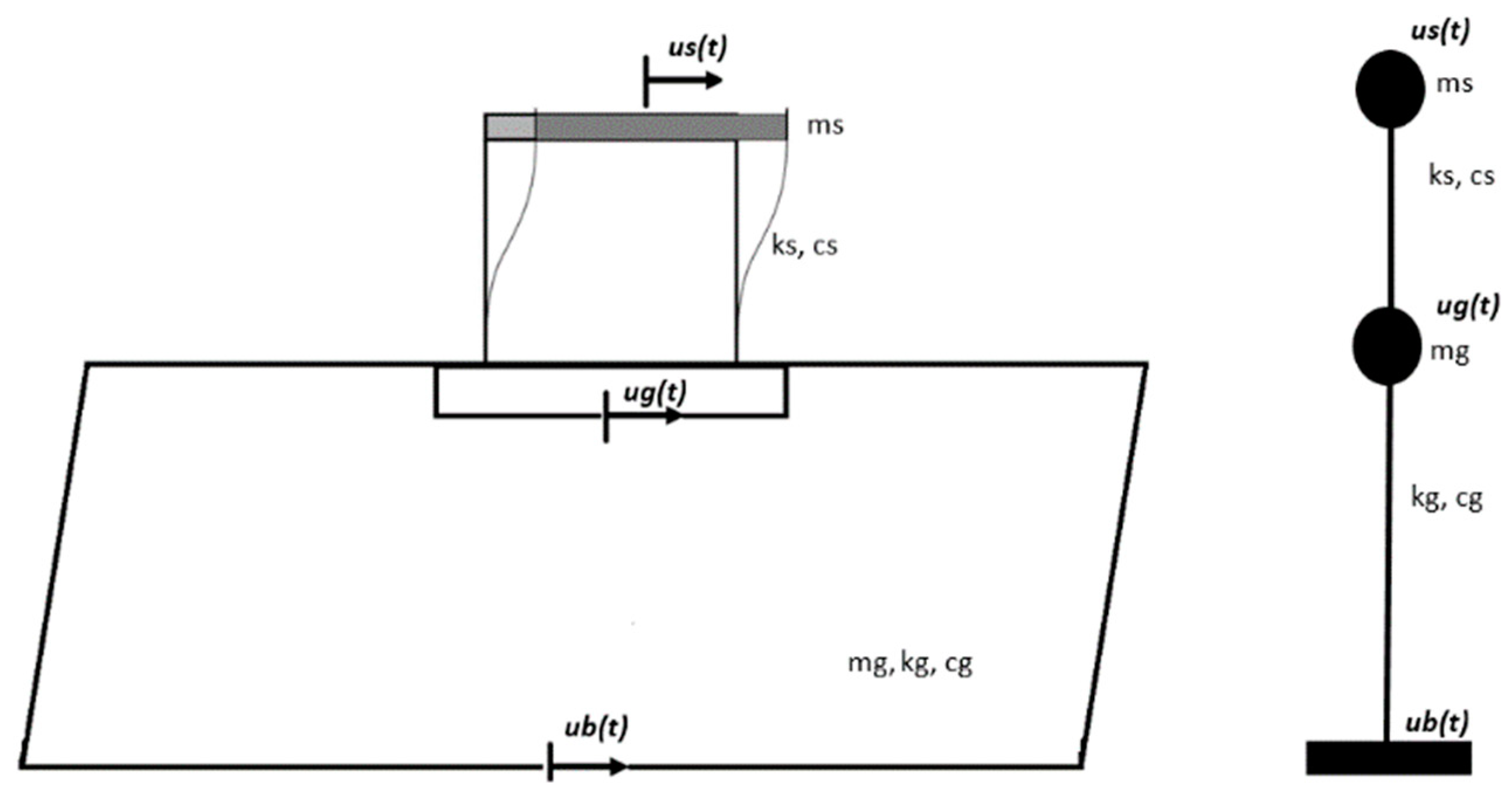
2. Two Degrees of Freedom (2-DOF) Model
The first step of the proposed methodology consists of modelling the soil–foundation structure system with a simplified 2-DOF model (
Figure 1), whose cinematics may be described in terms of:
The preliminary assumption consists of considering the longitudinal direction of the motion, neglecting the rotations.
Applying the second Newton’s law to both masses (ms: structural mass and mg: ground mass), the equation of motion may be written as:
conveniently, it is possible to re-write (1) and (2) by merging the kinematic terms together: accelerations (
, velocities (
, displacements
:
and thus, in the matrix form, the equations of motion of the 2-DOF system may written as:
where:
is the mass matrix;
is the damping matrix;
is the stiffness matrix;
u = is the displacement vector;
r = is the base vector
2.1. Period Elongation
The natural frequencies of the system can be found by solving the eigenvalue problem:
The equation may be easily solved by putting:
and:
and by dividing (7) with
:
The solution of (11) leads two roots, given by:
where the term under the square root is the discriminant that may be rewritten as:
Since soil structure interaction effects are significant when the structural frequency is larger than that of the soil (
,
(13) may be rewritten as:
Substituting (14) inside (12), leads to the two natural frequencies of the system:
(15) and (16) may be rewritten as:
and consequently, the fundamental periods of the system are:
It is worth noting that, since and are small values, T2 is bigger than T1 and the coefficient describes the period elongation that is demonstrated to depend both on the ratio of the masses and on the ratio between the frequencies of the structure mass and of soils. T1 is the first natural period of the system and depends on the structural characteristics. For small T1 can be approximated with TS (Equation (19)).
2.2. Damping
The 2-DOF model considers the damping as the second effect of SSI. Assuming that the damping is low enough to maintain the orthogonality properties of the mode shapes, it is possible to write:
where:
and are the damping ratios, respectively: and
and are the modal participation factors for the two mode shapes of the system and M1 and M2 are the masses in the first and second mode:
and
Finally,
and
are the mode shapes, that can be calculated by introducing (17) and (18) inside:
Solving by setting :
The first mode shape
is given (by setting
and the second mode shape
is given (by setting
Equation (27) may be rewritten as:
Equation (28) shows that the damping of the system consists of two contributions: the first is proportional to the soil damping (
and the second term depends on the contribution of the structural damping
. In particular, Equation (28) indicates also that the damping of the equivalent system is larger than the damping ratio of the structure itself, confirming previous findings, such as [
1].
2.3. Soil Parameters
The dependency of period elongation and damping increase have been shown to depend on the coefficient
and consequently on the soil mass that is relatively complex to calculate. In this regard, following the approach in [
1], soil frequency can be calculated as:
Therefore, considering the soil as an equivalent 1-DOF system:
where vs. is the shear wave velocity and H is the depth of a uniform layer of isotropic, linear elastic soil underlying rigid bedrock [
1], it is possible to calculate the soil mass as:
Finally, the stiffness of the soil can be defined [
1] as:
It is worth noting that previous publications, such as [
1], proposed that period elongation and damping increase depend on the ratio between the translational and rotational stiffness of the structure and of the system. Here instead
and
are defined by considering the physical parameters of both the soil (see Equations (31) and (32)) and the structure and thus avoiding to consider empirical definitions of the stiffness. In addition, Equations (20) and (28) confirmed that (1) SSI is relatively significant for cases of flexible structures on stiff soil deposits, as shown in [
1]; (2) SSI may be significant for stiff structures founded on soft soils; (3) the fundamental period of soil-structure system is longer than that of fixed-base structure (period elongation); (4) damping of soil-structure system is higher than the damping of the structure alone.
3. Numerical Models
In this section, two series of numerical models are considered: with (1) fixed-base and (2) SSI. Several case studies are herein performed by considering several values of the height of the soil layer and the shear wave velocity. In particular, the case studies consider a 2-floor shear-type building (representing a low-rise residential structure) founded on shallow foundations. Sixteen finite-element models were performed in order to assess the mutual interaction between the soil and the structure. The first one consists of the fixed-based (SSI neglected) structure while the other 15 cases are based on soil layers with different characteristics: different depths (10, 20 and 30 m) and stiffness (100 m/s, 200 m/s, 300 m/s, 400 m/s and 500 m/s).
The 3D numerical models (soil + foundation + structure,
Figure 2,
Figure 3 and
Figure 4) were performed with OpenSees PL, [
25,
26]. In order to reasonably maintain the computational costs some assumptions were considered. First of all, (1) the foundation slab was modelled as rigid adopting an equivalent linear elastic material with large stiffness, (2) deformations inside the foundations, soil and intermediate nodes along the structure were calculated but not memorized. (3) The floors were considered rigid by introducing rigid diaphragms instead of deformable beams.
FIXED model: the nodes at the base of the structure were restrained in all six directions (longitudinal, transversal and vertical) to fix the structure at the base by neglecting the effects of SSI. This model was used to calculate the periods (0.13 s and 0.04 s) and verify that the first one is representing the dynamic behaviour of the structure (participation mass: 89%). The building is regular in plan (30 m × 20 m rectangular base) and regular along its height (3.3 m, each floor, total height: 6.6 m, above ground level). The seismic-resistant system consists of RC columns (three in longitudinal direction, 6 m spaced, and three in transversal direction, 6 m spaced) that were modelled with elastic beam column elements (11 elements for each floor, parameters: Young’s modulus 3.5 × 10
7 kN/m
2 and shear modulus: 1.73 × 10
7 kN/m
2). The seismic masses were concentrated in correspondence with the connections between the beams and the columns and the floor were tied together to maintain a shear-type behavior, by following the approach already proposed in [
27,
28].
SSI models: the 15 numerical models were built up to realistically represent non-linear behaviours of the soil consisting of amplitude-dependent amplifications (or de-amplifications), plastic accumulations of ground deformation, and permanent movements (rotations, longitudinal displacements) of the entire system (soil + foundation + structure). Advanced material models were adopted in order to represent the high non-linear behaviour of a weak ground soil.
The foundation consists of a 0.50 m-thick RC rigid slab (28.4 × 34.4 m) designed by calculating the eccentricity loads (the ratio between the overturning bending moment and the vertical force) in the most detrimental way (minimum vertical loads and maximum bending moments) at foundation level. The bearing pressure of the building is: 195 kPa. EqualDOF [
26] were used to link together the nodes at the base of the columns and the ones belonging to the foundation in order to model the slab as a rigid element. The nodes of the interface between the column and the foundation were connected with a horizontal rigid beam-column link to model the continuity of the link slab-column. Two solutions were applied to allow continuity of deformation between the foundation (equivalent concrete material) and the soil. (1) Foundations were modelled with pressure independent multi-yield (PIMY), the same model as the soil and consisting of a non-linear hysteretic material with a Von Mises multi-surface kinematic plasticity (
Table 1), allowing the continuity among the two models and (2) the interface between the nodes belonging to the foundations and those of the soil were realized with zero length elements to guarantee the balance at each step and avoid convergence problems. Therefore, the models allow us to represent uplifts and gapping between the foundation and the soil, as well as other non-linear effects due to SSI.
The surrounding soil was also modeled with PIMY (
Table 2,
Figure 5) in order to ensure the connectivity among the two models. In addition, zero length elements were used to represent the interface between the foundation slab and the nodes belonging to the surrounding soil.
Three models of the soil were built with 3D meshes (
Figure 2,
Figure 3 and
Figure 4) with different depth (10, 20 and 30 m, named respectively Model1, Model2 and Model3) and thus with different characteristics in terms of dimensions and number of nodes and BrickUP elements (See
Table 3). The soil was modeled with a PIMY model, whose non-linear behavior is described by hyperbolic backbone curve that models the relationship between the shear strains and the shear stresses. A parametric study was carried on two parameters: soil density (1.5, 1.8 and 2.1 kN/m
2, respectively for S1, S2 and S3) and the shear wave velocity that was varied between 100 m/s to 500 m/s.
Figure 6,
Figure 7 and
Figure 8 show the non-linear backbone curves, represented by hyperbolic relations defined by the strain shear modulus and ultimate shear strength, while the representative parameters are shown in
Table 4,
Table 5 and
Table 6. The mesh was defined by following the approach included in [
27,
28]. Every element is built with 20 nodes with three translational DOF, recorded using OpenSees Node Recorder at the corresponding integration points [
23]. The number of elements was defined on the basis of a maximum frequency (15 Hz) above which the spectral content of the input may be considered negligible and the element dimensions were increased with the distance to the center of the piles. Transmitting boundaries were considered at the base to dissipate the radiating waves and to accurately model the damping by preventing the reflection of the seismic waves back into the soil medium after being incident on the far-off boundaries. Vertical direction (described by the third DOF) was constrained. Lateral boundaries were modelled by adopting the penalty method (tolerance: 10-4) to avoid problems associated with the equations system conditions. Vertical directions were restrained while longitudinal and transversal directions were set free to allow soil shear deformations.
4. Validation Results
In this section the comparison between the numerical simulations (totally 45 models) and Equation (20) are compared in order to validate and discuss the proposed models.
Figure 9 shows the comparison between the results from Finite Element Model (FEM) and the results from Equation (20) for the 45 performed models.
First or all, it is worth noting that the fundamental periods increase with the depth of the soil layer, as expected, since the system period depends on both and that are proportional to H−2 (thickness of soil layer), and thus T is proportional to H.
In addition, for all the models, the smallest values of vs. (100 m/s) give the maximum values of fundamental period, meaning that soil deformability is important in elongating the periods. This is also expected by Equation (20), since is proportional to the shear wave velocity and thus T is inversely proportional to Vs.
Moreover, the results show that the values provided by the proposed formulation are close to those derived from FEM models. The maximum difference occurs for Model 1 (H = 10 m), for the most rigid soils (Vs = 500 m/s) with +6.71%, 6.92% and 7.34% for S1, S2 and S3, respectively. Therefore, it is possible to see that (1) the proposed formulation is validated by the numerical simulations even if realistic soil mechanisms such as non-linear deformations and plasticity reduce period elongation. (2) The proposed formulation gives small discrepancies of the periods (not necessarily conservative) for the system.
5. Equivalent Fixed-Based Structure (EQ) Model
The proposed formulation was herein applied to perform the equivalent fixed-based structure (EQ model) that represents Model 2 (H = 20 m): S21 (density = 1.8 kN/m
2 and Vs = 100 m/s). Parameters
and
were calculated by (9)–(10) and resulted as 0.03 and 0.001469, respectively. Two assumptions were considered: (1) structural masses were proportionally increased to obtain 0.80 s as the fundamental period (compare with
Figure 9b) and (2) the parameter η (η = 0.778, [
29]) was applied to account for the increased damping of the system (11.5%, instead of the conventional 5%).
Ten input motions were selected from the NGA database on the basis of the Eurocode prescriptions to be compatible with the code-specified spectrum for the life-safety limit state (corresponding to an earthquake with a return period of 475 years, lat.: 42.333 N, 14.246 E., S = 1.50714, Tb = 0.257 s, Tc = 0.770 s, Td = 2.538, Cc = 2.02847, NTC).
Figure 10 shows the selected elastic response spectra (pseudo-spectral acceleration vs. period) and the mean spectral ordinates. Note that the mean spectrum (calculated among the selected ones) is included between the −10% and +30% of the code-based spectral shape, as prescribed in [
30].
Table 7 shows the characteristics of the selected input motions in terms of peak ground acceleration (PGA), peak ground velocity (PGV) and peak ground displacement (PGD). Note that five of the selected input motions were taken from near field (NF) motions and five from far field (FF) ones. In addition, the set was selected to have significantly dispersion of intensities to significantly affect the dynamic characteristics of the system.
The non-linear dynamic analyses were performed with the longitudinal component of the input motions that was applied at the base of the model. As in [
31], the large dimension of the 3D model needs to consider several steps in the analyses. In the first step the soil (without the structure and foundation) was loaded and linear properties (weight, shear and bulk modulus) were considered. In step 2, the soil properties were changed from elastic to plastic (in 25 load steps). In step 3 structural loads were applied and finally dynamic analyses were performed in step 4. The NewtonLineSearch algorithm was used to increase the speed of the solution.
6. Results
Figure 11 shows the results in terms of top acceleration spectra for the selected 10 input motions, for the two models (SSI and EQ model). SSI is the finite element model described in
Section 3, while the EQ model is the equivalent fixed-based model with fundamental period 0.80 s and 11.5% damping. It is worth noting that the peak values occur at the fundamental period of the system, demonstrating that both models work properly. Moreover, SSI model results are conservatively smaller than those calculated for the EQ model with a range of 84.0% for BOL and 95.5% for MUL. In particular, the shape of the spectra for many input motions is close between the two models, especially for FF input motions. It is important to notice that the application of the damping (11.5%) and thus the reduction of the input motion by the parameter η allows us to obtain realistic values of the spectra. In only two cases (PER and YER) the values are larger than those calculated by the SSI model. In particular, for these input motions, the differences occur for PGA > 1 g. In one case (BRN), for some values EQ results are not conservative, if compared with SSI cases, and this may be due to the effects of soil non-linear mechanisms that cannot be included in the equivalent fixed model. However, the general trends of the EQ spectra are similar and demonstrate that the proposed methodology is able to represent the amplifications due to site and basin effects. In this regard, five input motions (ERZ, ATM; BOL, CHY and YER) show amplifications at higher periods that are conservatively represented by the EQ spectra in a close way. For RRS, the site effects are represented but with a delay: the peak value for the SSI model (4.97 m/s
2) occurs for 1.7 s, while the peak one for EQ is 6.40 m/s
2, occurring at 1.9 s, with a delay of 0.2 s. Moreover, it is worth noting that for FF cases, the EQ model seems to be more representative than for the cases of NF, where the differences between the two models are more significant. Overall, the proposed EQ model that implements Equations (20) and (28), is shown to be conservatively correct to represent the complex mechanism due to the SSI between the structure and the soil.
7. Conclusions
The paper assesses the effects of SSI with an equivalent fixed based model (named EQ model) that consider the effects of SSI by applying the period elongation and the damping increase. These parameters were firstly calculated with simplified 2-DOF dynamic models and thus applied to represent the EQ models. Numerical simulations were carried out to verify the accuracy of the models in terms of period elongation, that were compared and shown to be appropriately similar. Moreover, a case study was performed with several input motions (both near and far field) to assess the potentialities of the approach to conservatively represent the mechanisms of soil deformability. The overall outcome is that the proposed framework performs correctly and may realistically represent the complex SSI effects, allowing us to save time and reduce the complexities of more realistic three-dimensional highly non-linear models. In particular, this approach may be used when a preliminary design of complete (soil + foundation + structure) systems is required. In this regard, more comparative studies will be object of future work.


