
A Novel Accelerated Corrosion Test for Supporting Devices in a Floating Photovoltaic System


Abstract
:Featured Application
Abstract
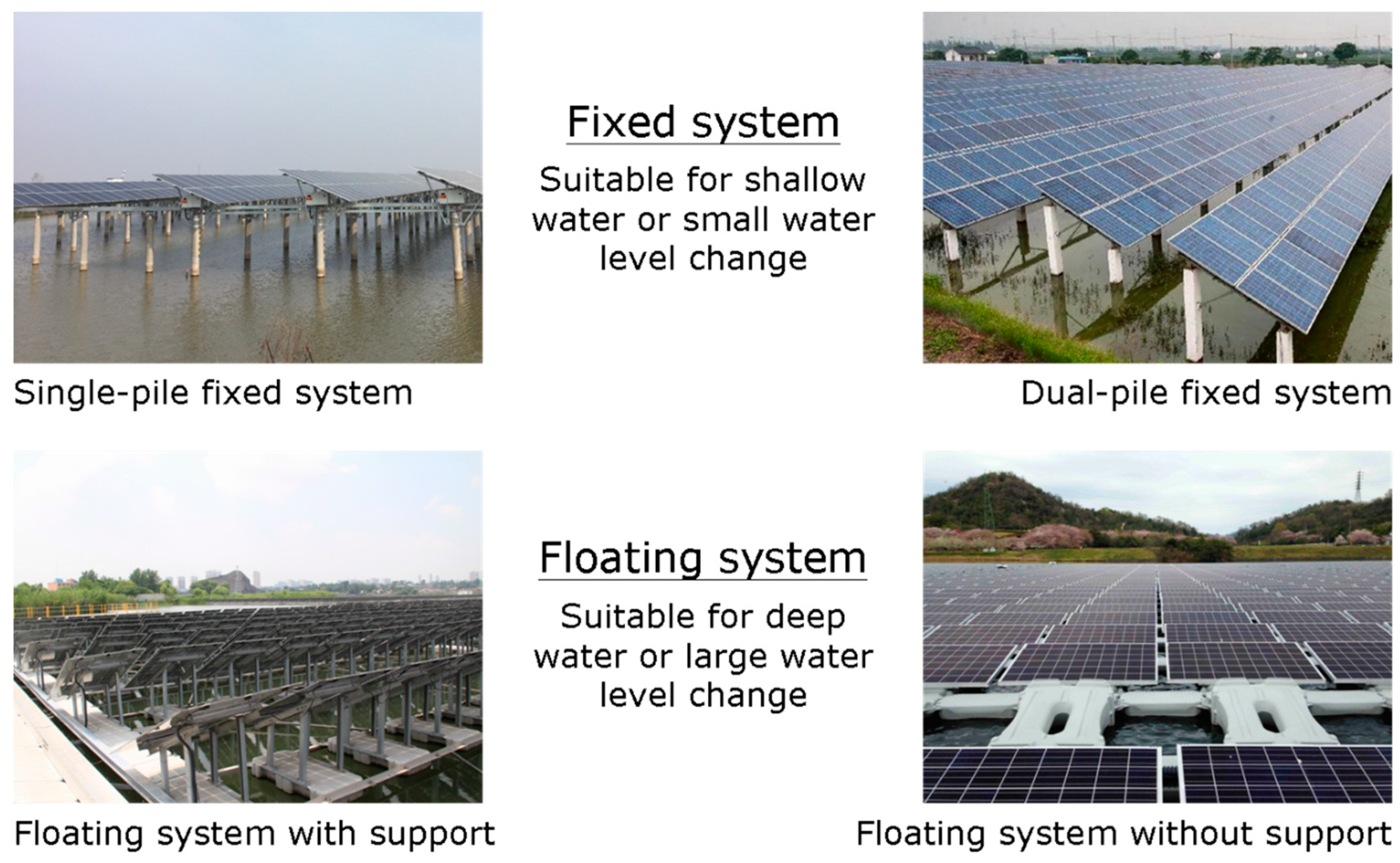
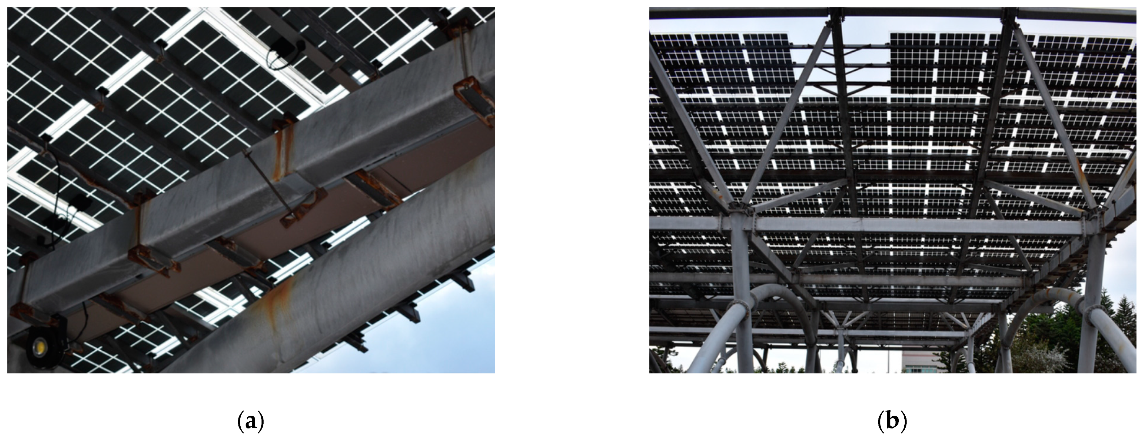
1. Introduction
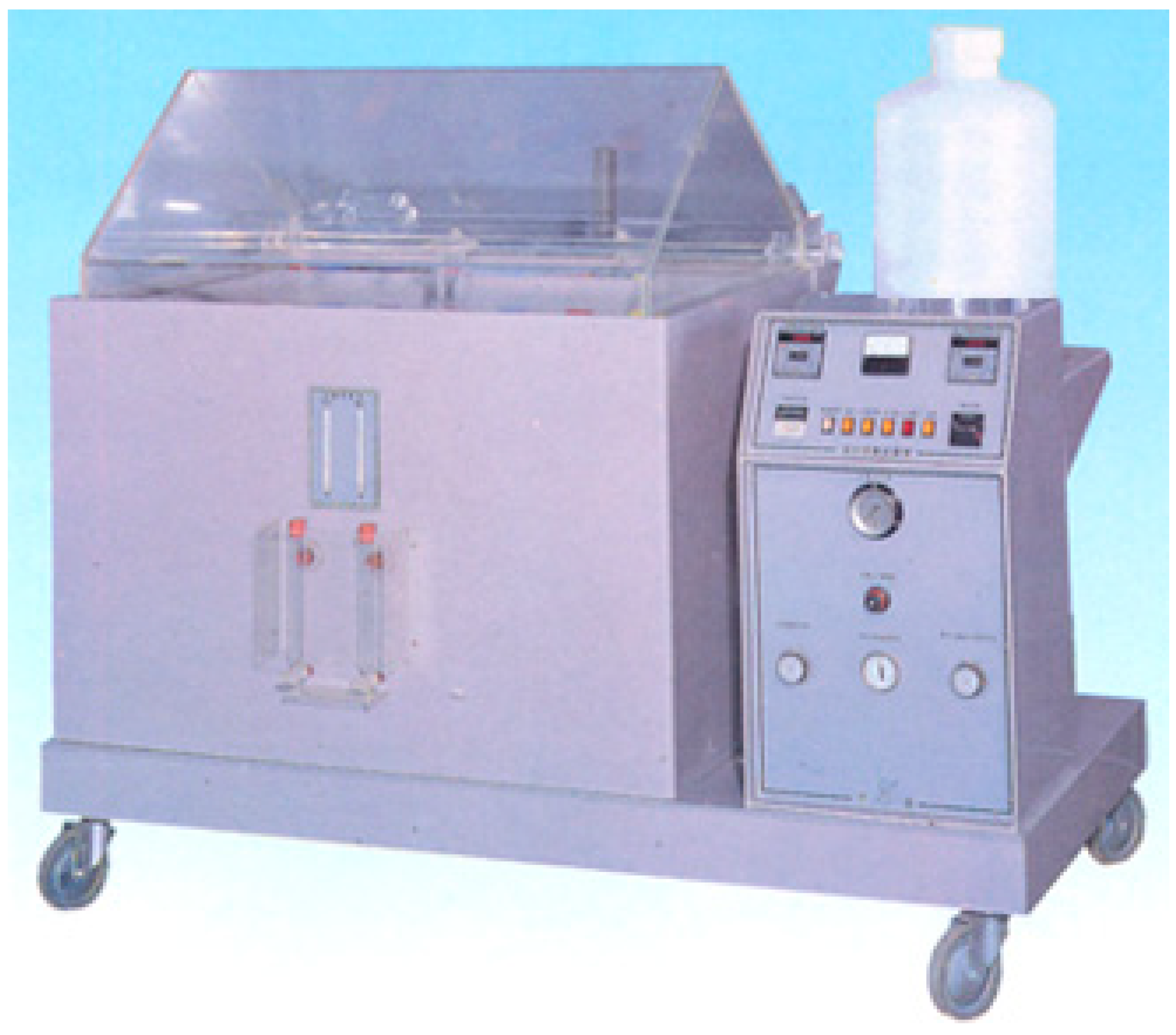
2. Materials and Methods
- Concentration of salt solution: 5 ± 0.5% NaCl + 0.0205 ± 0.0015% CuCl2
- pH of salt solution: 3.1–3.3
- Temperature of salt solution and spray chamber: 50 ± 2 °C
- Pressure of saturated compressed air: 98 ± 10 kPa
- Average fog collection rate for a horizontal collecting area of 80 cm2: 1.5 ± 0.5 mL/h.
- Test time: depending on the extent of corrosion.
3. Results and Discussion
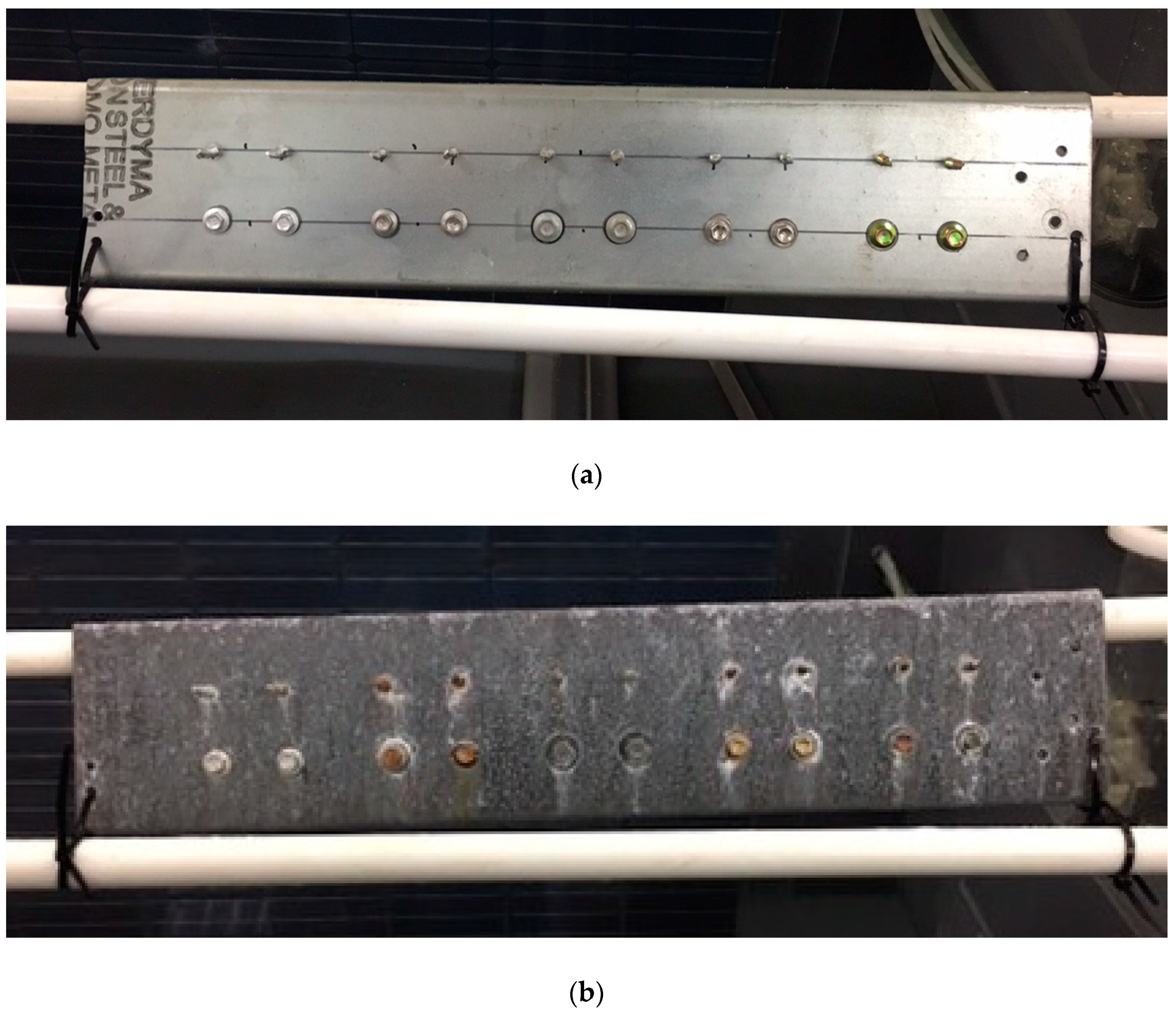
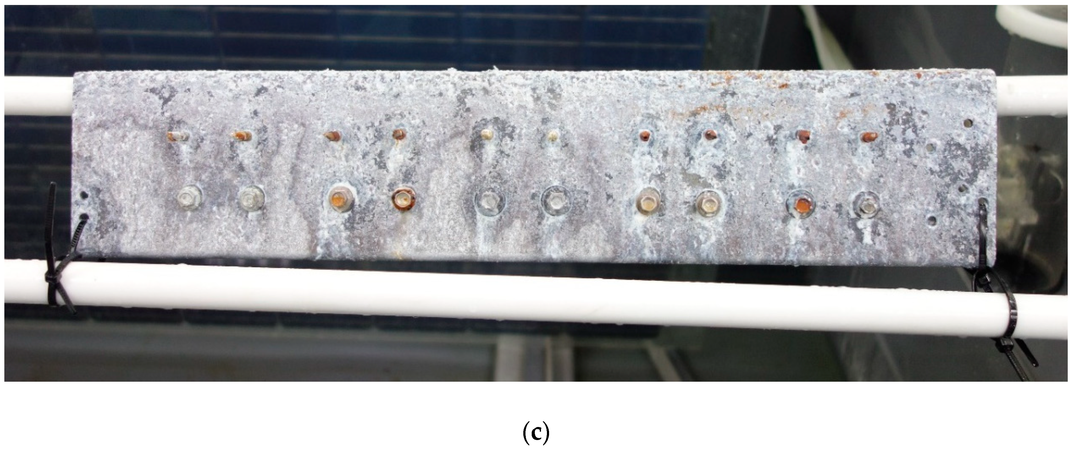
3.1. SUPERDYMA Shape Steel and Five Types of Screw
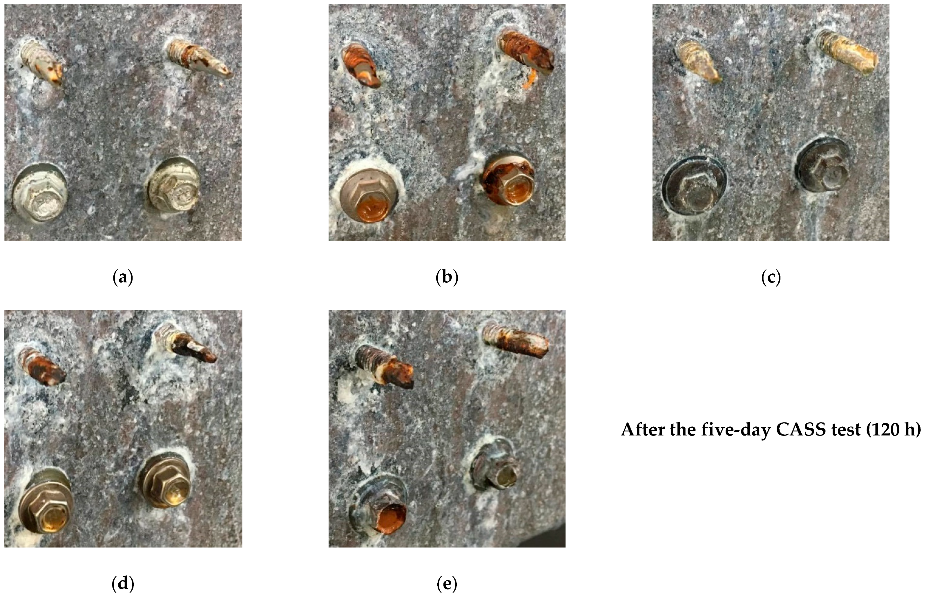
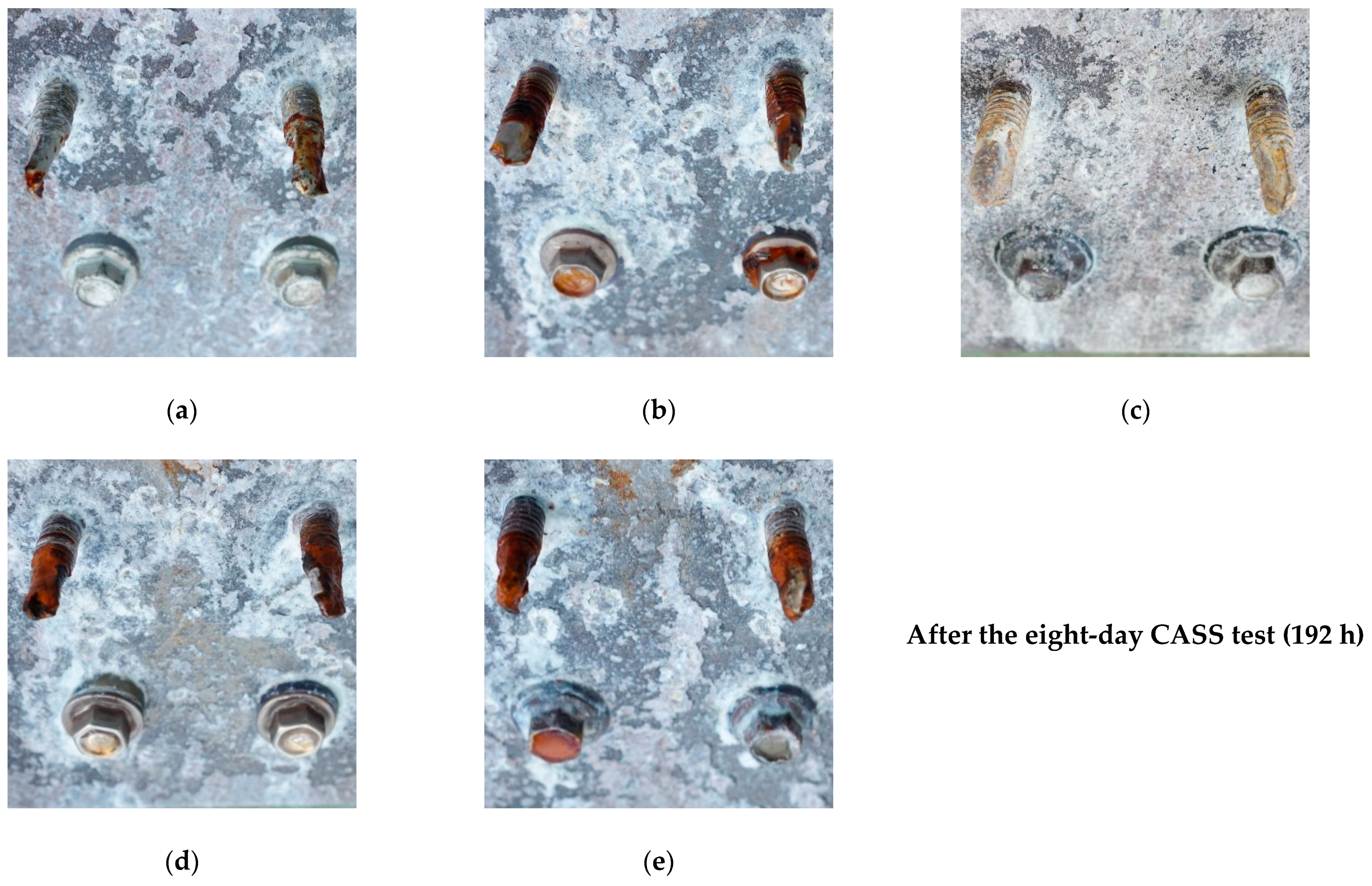
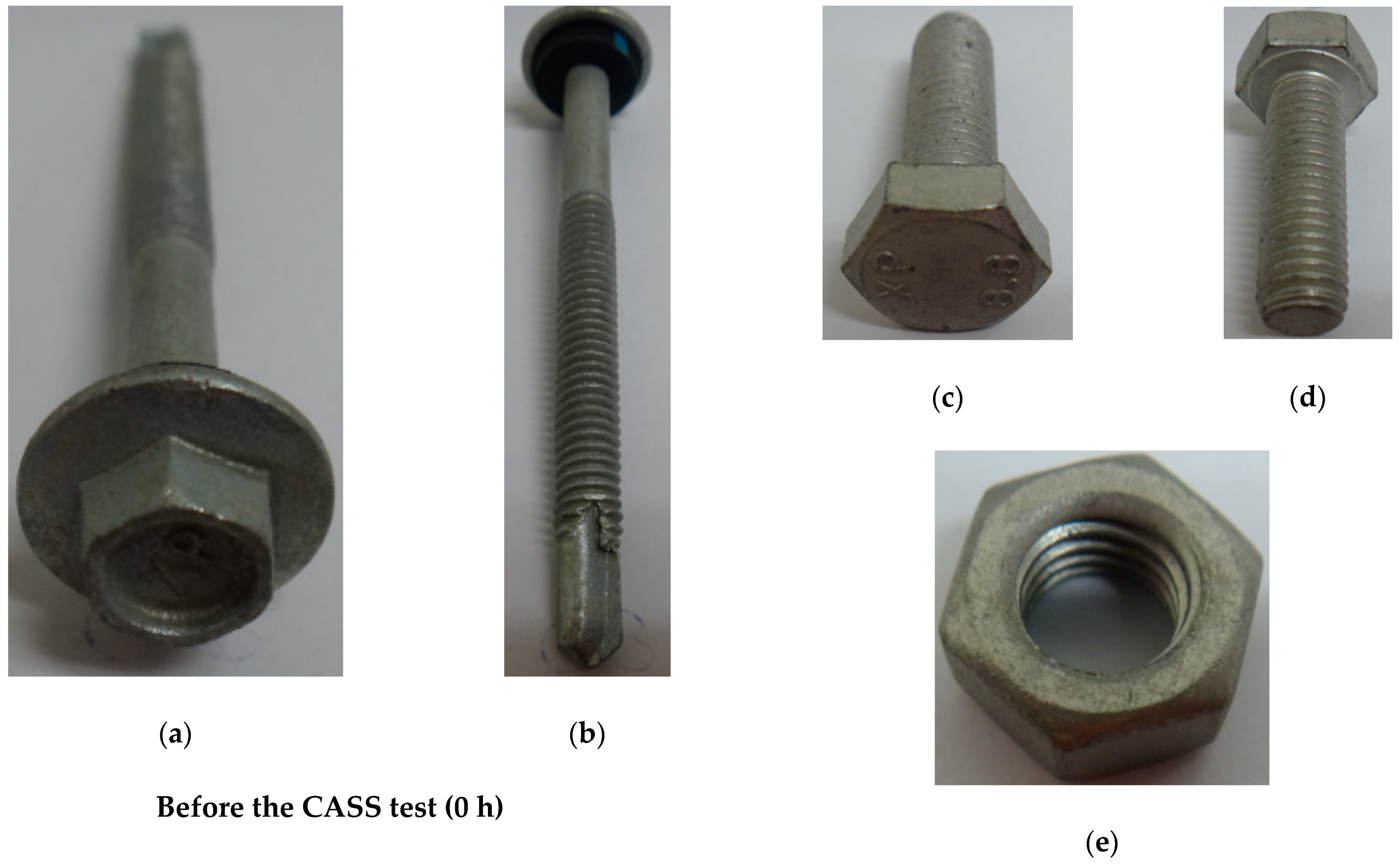
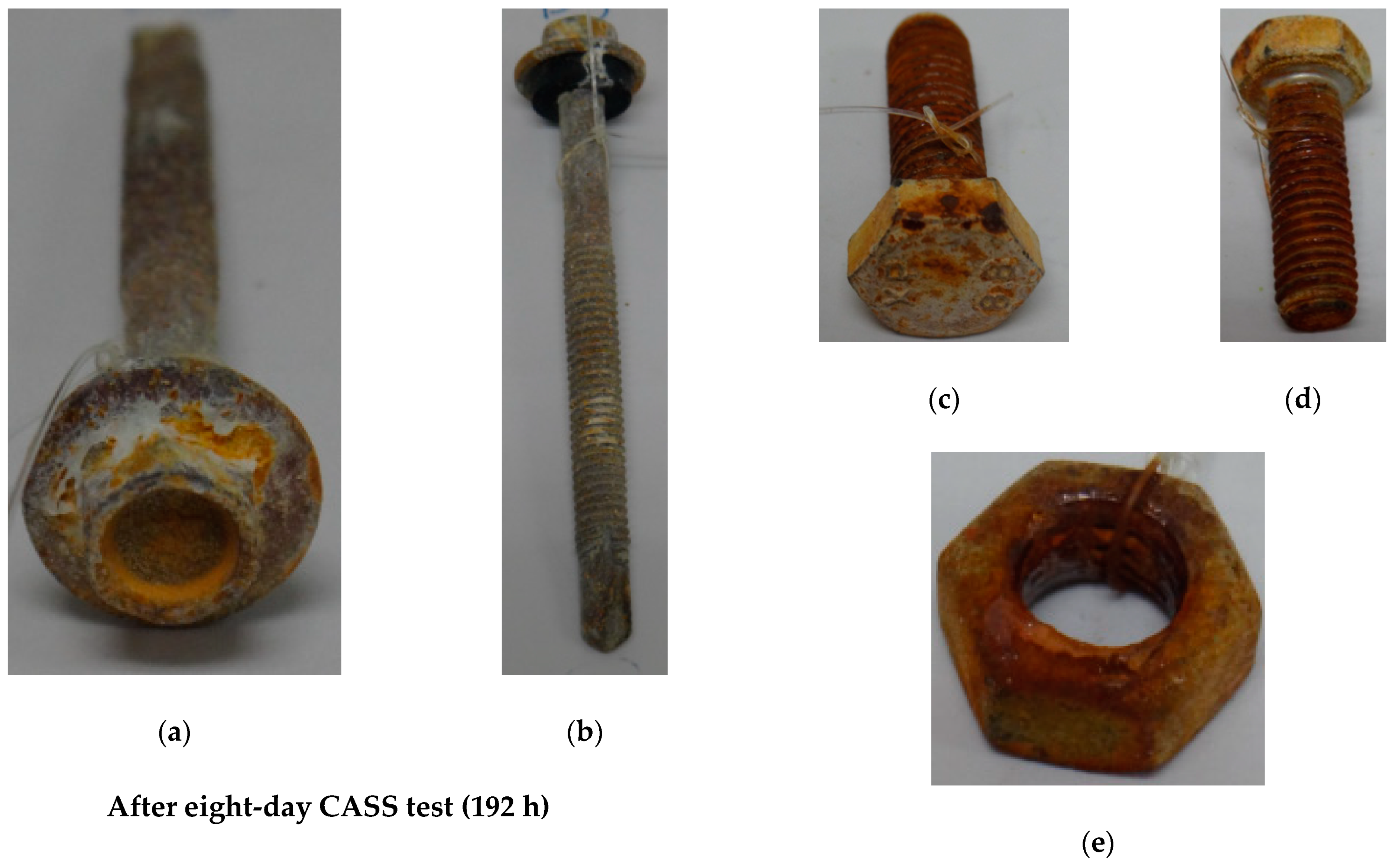
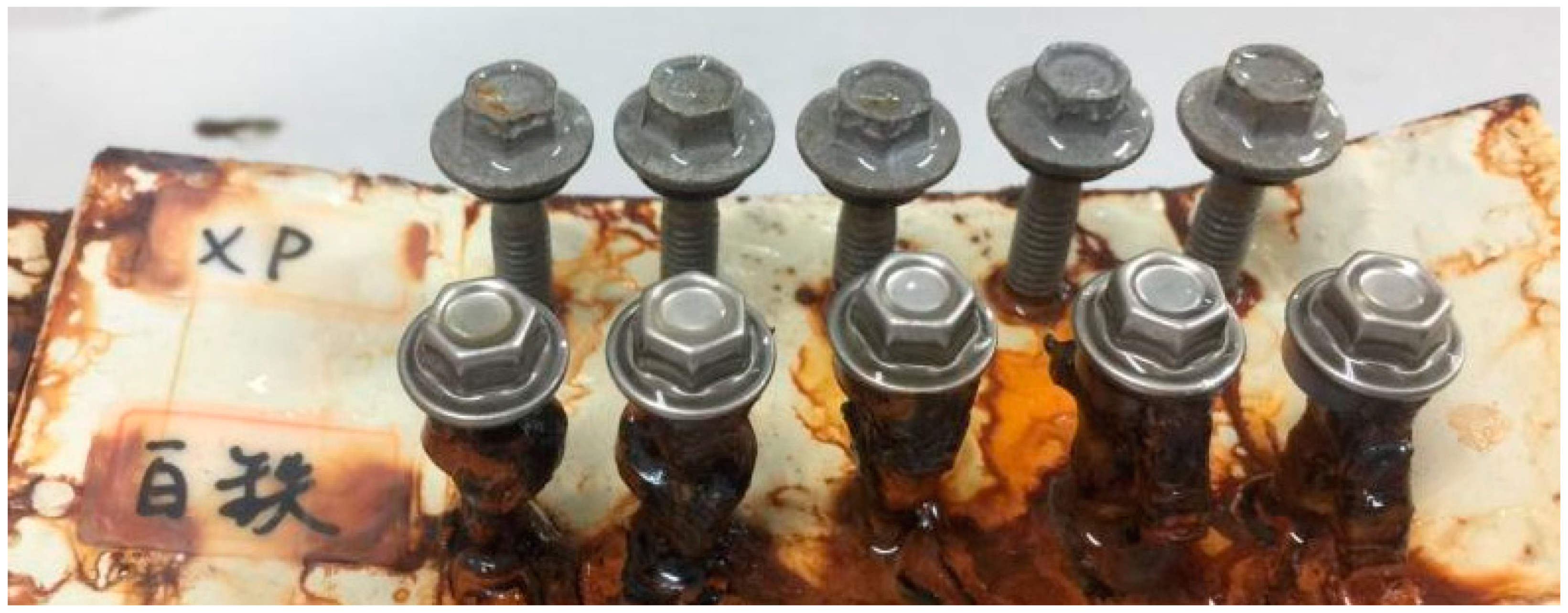
3.2. ALZIN XP Screws/Bolts/Nuts
4. Conclusions
Author Contributions
Funding
Institutional Review Board Statement
Informed Consent Statement
Data Availability Statement
Conflicts of Interest
References
- Trapani, K.; Redón Santafé, M. A Review of Floating Photovoltaic Installations: 2007–2013. Prog. Photovolt. Res. Appl. 2015, 23, 524–532. [Google Scholar] [CrossRef] [Green Version]
- Abid, M.; Abid, Z.; Sagin, J.; Murtaza, R.; Sarbassov, D.; Shabbir, M. Prospects of Floating Photovoltaic Technology and Its Implementation in Central and South Asian Countries. Int. J. Environ. Sci. Technol. 2019, 16, 1755–1762. [Google Scholar] [CrossRef]
- Kim, S.-H.; Yoon, S.-J.; Choi, W.; Choi, K.-B. Application of Floating Photovoltaic Energy Generation Systems in South Korea. Sustainability 2016, 8, 1333. [Google Scholar] [CrossRef] [Green Version]
- Kim, S.-M.; Oh, M.; Park, H.-D. Analysis and Prioritization of the Floating Photovoltaic System Potential for Reservoirs in Korea. Appl. Sci. 2019, 9, 395. [Google Scholar] [CrossRef] [Green Version]
- Sahu, A.; Yadav, N.; Sudhakar, K. Floating photovoltaic power plant: A review. Renew. Sustain. Energy Rev. 2016, 66, 815–824. [Google Scholar] [CrossRef]
- International Organization for Standardization. Corrosion of Metals and Alloys—Corrosivity of Atmospheres—Classification, Determination and Estimation; ISO 9223; International Organization for Standardization: Geneva, Switzerland, 2012. [Google Scholar]
- Institute of Tansportation, Ministry of Transportation and Communications. 2016 Annual Report of Atmospheric Corrosive Factors Data in Taiwan, 1st ed.; Institute of Tansportation, Ministry of Transportation and Communications: Taipei, Taiwan, 2017.
- Choi, Y.-K.; Hwang, S.-H.; Lee, J.-H. Development of Anticorrosive Materials for Floating Offshore Photovoltaic Systems. Sci. Adv. Mater. 2017, 9, 1408–1414. [Google Scholar] [CrossRef]
- Li, Y.-F.; Ning, C.-Y. Latest Research Progress of Marine Microbiological Corrosion and Biofouling, and New Approaches of Marine Anti-Corrosion and Anti-Fouling. Bioact. Mater. 2019, 4, 189–195. [Google Scholar] [CrossRef] [PubMed]
- Mariello, M.; Guido, F.; Mastronardi, V.M.; Giannuzzi, R.; Algieri, L.; Qualteri, A.; Maffezzoli, A.; De Vittorio, M. Reliability of Protective Coatings for Flexible Piezoelectric Transducers in Aqueous Environments. Micromachines 2019, 10, 739. [Google Scholar] [CrossRef] [PubMed] [Green Version]
- Wang, E.; Yen, K.-H.; Wang, C.; Ji, L.; Zgonena, T. Accelerated Aging Tests on PV Grounding Connections. Energy Procedia 2011, 12, 578–585. [Google Scholar] [CrossRef] [Green Version]
- Wang, X.-F.; Bao, Y.-W.; Liu, X.G.; Qiu, Y. Effects of Salt Spray Corrosion on Durability of Laminated Photovoltaic Glass. Key Eng. Mater. 2018, 768, 246–250. [Google Scholar] [CrossRef]
- Osterwald, C.R.; McMahon, T.J. History of Accelerated and Qualification Testing of Terrestrial Photovoltaic Modules: A Literature Review. Prog. Photovolt. Res. Appl. 2009, 17, 11–33. [Google Scholar] [CrossRef]
- International Organization for Standardization. Corrosion Tests in Artificial Atmospheres—Salt Spray Tests; ISO 9227; International Organization for Standardization: Geneva, Switzerland, 2017. [Google Scholar]
- International Electrotechnical Commission. Salt Mist Corrosion Testing of Photovoltaic (PV) Modules; IEC 61701; International Organization for Standardization: Geneva, Switzerland, 2001. [Google Scholar]
- Bureau of Standards, Mertology and Inspection, Ministry of Economic Affairs. Methods of Salt Spray Testing; CNS 8886; Bureau of Standards, Metrology and Inspecion, the Ministry of Economic Affairs: Taipei, Taiwan, 2002.
- Liu, H.; Krishna, V.; Leung, J.L.; Reindl, T.; Zhao, L. Field Experience and Performance Analysis of Floating PV Technologies in the Tropics. Prog. Photovolt. Res. Appl. 2018, 26, 957–967. [Google Scholar] [CrossRef]
- Sudhakar, K. SWOT Analysis of Floating Solar Plants. MOJ Sol. Photoenergy Syst. 2019, 3, 20–22. [Google Scholar]
- Chen, W.-B.; Chen, P.; Chen, H.Y.; Wu, J.; Tsai, W.-T. Development of Al-Containing Zinc-Rich Paints for Corrosion Resistance. Appl. Surf. Sci. 2002, 187, 154–164. [Google Scholar] [CrossRef]
- Nishimura, K.; Kato, K.; Shindo, H. Highly Corrosion-Resistant Zn-Mg Alloy Galvanized Steel Sheet for Building Construction Materials. Nippon Steel Tech. Rep. 2000, 81, 85–88. [Google Scholar]
- Li, K.-L.; Liu, Y.; Tu, H.; Su, X.-P.; Wang, J.H. Effect of Si on the Growth of Fe-Al Intermetallic Layer in Zn-11%Al-3%Mg Coating. Surf. Coat. Technol. 2016, 306, 390–396. [Google Scholar] [CrossRef]
- Schuerz, S.; Fleischanderl, M.; Luckeneder, G.H.; Preis, K.; Haunschmied, T.; Mori, G.; Kneissl, A.C. Corrosion Behaviour of Zn-Al-Mg Coated Steel Sheet in Sodium Chloride-Containing Environment. Corros. Sci. 2009, 51, 2355–2363. [Google Scholar] [CrossRef]
- Ueda, K.; Takahashi, A.; Kubo, Y. Investigation of Corrosion Resistance of Pre-Painted Zn-11%Al-3%Mg-0.2%Si Alloy Coated Steel Sheet through Outdoor Exposure Test in Okinawa. Metall. Ital. 2012, 3, 13–19. [Google Scholar]
- Ryu, H.-S.; Jeong, D.-G.; Lee, H.-S. Corrosion Protection of Steel by Applying a Zn-Sn Metal Spray System. J. Korea Inst. Build. Const. 2014, 14, 505–513. [Google Scholar] [CrossRef] [Green Version]
- Oladijo, O.P.; Mathabatha, M.H.; Popoola, A.P.I.; Ntsoane, T.P. Characterization and Corrosion Behaviour of Plasma Sprayed Zn-Sn Alloy Coating on Mild Steel. Surf. Coat. Technol. 2018, 352, 654–661. [Google Scholar] [CrossRef]
- Fatoba, O.S.; Popoola, A.P.I.; Fedotova, T. Characterization and Corrosion Behaviour of Zn-Sn Binary Alloy Coatings in 0.5 M H2SO4 Solution. J. Electrochem. Sci. Technol. 2015, 6, 65–74. [Google Scholar] [CrossRef]
- Khireche, S.; Boughrara, D.; Kadri, A.; Hamadou, L.; Benbrahim, N. Corrosion Mechanism of Al, Al-Zn and Al-Zn-Sn Alloys in 3 wt.% NaCl Solution. Corros. Sci. 2014, 87, 504–516. [Google Scholar] [CrossRef]
- Morimoto, Y.; Honda, K.; Nishimura, K.; Tanaka, S.; Takahashi, A.; Scindo, H.; Kurosaki, M. Excellent Corrosion-Resistant Zn-Al-Mg-Si Alloy Hot-Dip Galvanized Steel Sheet “SUPERDYMA”. Nippon Steel Tech. Rep. 2003, 87, 24–26. [Google Scholar]
- Edavan, R.P.; Kopinski, R. Corrosion Resistance of Painted Zinc Alloy Coated Steels. Corros. Sci. 2009, 51, 2429–2442. [Google Scholar] [CrossRef]

| Test Method Item | Neutral Salt Spray (NSS) | Acetic Acid Salt Spray (ASS) | Copper-Accelerated Acetic Salt Spray (CASS) |
|---|---|---|---|
| Temperature | (35 ± 2) °C | (35 ± 2) °C | (50 ± 2) °C |
| pH (collected solution) | (6.5–7.2) | (3.1–3.3) | (3.1–3.3) |
| Concentration of sodium chloride (collected solution) | (50 ± 5) g/L | ||
| Average collection rate for a horizontal collecting area of 80 cm2 | (1.5 ± 0.5) mL/h | ||
| Periods of test | 2, 6, 24, 48, 96, 168, 240, 480, 720, and 1008 h | ||
Publisher’s Note: MDPI stays neutral with regard to jurisdictional claims in published maps and institutional affiliations. |
© 2021 by the authors. Licensee MDPI, Basel, Switzerland. This article is an open access article distributed under the terms and conditions of the Creative Commons Attribution (CC BY) license (https://creativecommons.org/licenses/by/4.0/).
Share and Cite
Liu, C.-K.; Kong, Z.-R.; Kao, M.-J.; Wu, T.-C. A Novel Accelerated Corrosion Test for Supporting Devices in a Floating Photovoltaic System. Appl. Sci. 2021, 11, 3308. https://doi.org/10.3390/app11083308
Liu C-K, Kong Z-R, Kao M-J, Wu T-C. A Novel Accelerated Corrosion Test for Supporting Devices in a Floating Photovoltaic System. Applied Sciences. 2021; 11(8):3308. https://doi.org/10.3390/app11083308
Chicago/Turabian StyleLiu, Chun-Kuo, Zhong-Ri Kong, Ming-Je Kao, and Teng-Chun Wu. 2021. "A Novel Accelerated Corrosion Test for Supporting Devices in a Floating Photovoltaic System" Applied Sciences 11, no. 8: 3308. https://doi.org/10.3390/app11083308