Article

Broadband Spectral Shaping of Regenerative Amplification with Extra-Cavity Waveplate for Cross Polarized Wave Generation

High-Intensity Laser and Particle Beam Laboratory, Department of Nuclear Physics, China Institute of Atomic Energy, Beijing 102413, China
*
Author to whom correspondence should be addressed.
Appl. Sci. 2022, 12(11), 5521; https://doi.org/10.3390/app12115521
Submission received: 27 April 2022 / Revised: 23 May 2022 / Accepted: 27 May 2022 / Published: 29 May 2022
(This article belongs to the Section Optics and Lasers)

Abstract

:
We demonstrated extra-cavity gain narrowing pre-compensating in a regenerative amplifier with a multi-order triple-wavelength waveplate (WP). With a 1.117 mm thickness quartz waveplate, which was placed on the stretcher, the gain narrowing effect was reduced efficiently, the output spectral bandwidth was broadened from 25 nm to 40 nm, the broadest spectral pulse was compressed to 33.2 fs and the output energy was 1.5 mJ, the as same as with no waveplate. Then, the amplified pulses were used for cross polarized wave (XPW) generation, and the generated XPW spectra were broadened from 45 nm without WP to 68 nm with WP, with a conversion efficiency of 15%. This simple method can produce broader output spectra with a broader seed beam.

1. Introduction

Since the advent of chirped-pulse amplification (CPA) technology, ultrafast laser amplification has experienced a revolution [1]. Output peak powers currently reach multi-petawatts (PW) and will be pursued to 100 PW in the future [2,3,4,5,6]. Due to the limitations of compressor grating and a large crystal size, it is more competitive to improve the peak power by reducing the pulse duration than by increasing the pulse energy. However, gain narrowing significantly reduces bandwidth during the amplification process, and thus it is difficult to achieve a shorter pulse duration.
Shorter pulse durations in CPA regenerative amplifiers have been demonstrated by reducing gain narrowing in two ways: intra-cavity and extra-cavity. For the intra-cavity way, spectral filters such as etalons [7], birefringent plates [7,8,9,10], special dielectric-coated mirrors [11], special dielectric-coated filters [12], acoustic-optic programmable dispersion filters (AOPDF) [13], optical rotatory dispersion spectral filters [14,15], polarization-encoded chirped pulse amplification [16,17] and modified polarization-encoded chirped pulse amplification [18] were used to compensate the gain narrowing effect. However, these intra-cavity spectral filters introduce high energy loss, increase the round-trip numbers of the seed beam in the amplification cavity and decrease the output energy. For the birefringent plates, Leng et al. [9,10] designed a birefringent plate considering the two parameters of incident angle and rotation angle, which made the design complex. The incident angle to the birefringent plate was between 10° to 20°, without a coating, which introduced large energy loss. For the extra-cavity way, special dielectric-coated filters or AOPDF were used to pre-compensate the gain narrowing effect. F. Verluise et al. inserted an AOPDF before the amplifier, and the output spectra were broadened from 35 nm to 75 nm [19]. Leng et al. made a specially coated filter with a transmission of ~40% near 730–830 nm [9]. It was inserted into the grating stretcher and before the amplifier, and the output spectra were broadened from 18 nm to 28 nm. The AOPDF device is expensive, and the special dielectric-coated filter with fixed spectral coating is difficult to optimize for the output spectra.
Here, we demonstrate extra-cavity gain compensation with a waveplate; a fused-silica multi-order triple-wavelength waveplate (WP) was designed and placed at the exit of the oscillator. Since the incident angle to the WP was roughly normal and the WP was coated with anti-reflection, it led to low energy loss of 50%. As a result, the output spectra of the regenerative amplifier were broadened from 25 nm to 40 nm, and the compressed pulse was 33.2 fs with 1.5 mJ of output energy. Then, the amplified pulses were used for cross polarized wave (XPW) generation, and the generated XPW spectra were broadened from 45 nm without WP to 68 nm with WP, with a conversion efficiency of 15%.

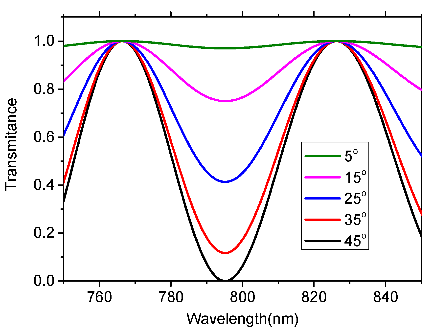
2. Gain Narrowing Pre-Compensating Method

For the multi-order triple-wavelength WP method, because the Ti:sapphire crystal gain peak is around 800 nm, 795 nm was chosen as a half WP, and two wavelengths (for example, ~760 nm and ~820 nm) further away from 795 nm were chosen as full WPs. Firstly, we assumed that the input light was in a vertical polarization and that the propagation direction of the input beam was normal to the WP surface. Then, it went through a Glan laser polarizer, which allowed the pure vertical polarization to pass. Secondly, through calculation, the differently optimized thickness was adjusted to realize the WP as a triple-wavelength WP. Finally, after the Glan laser polarizer, the transmittance was calculated for different optimized thicknesses. All the calculations were based on fundamental WP theory and the index refraction of quartz [20,21]:
d o p t = ( m + 1 2 ) λ 795 n m n e n o = n λ ~ 760 n m n e n o = k λ ~ 820 n m n e n o ,
T = 1 cos 2 2 φ sin 2 π d o p t λ ( n e n o ) ,
where dopt is the optimized quartz thickness, m, n and k are all integers, ne and no are refractive indices of the fast and slow axes, respectively, T is the transmittance and φ is the rotation angle between the input beam polarization and the fast axis of the WP.
Using Equation (1), the calculated optimized quartz thicknesses were 1.117 mm, 1.027 mm, 0.938 mm, 0.849 mm, 0.759 mm, 0.67 mm, 0.58 mm, 0.491 mm, 0.402 mm and 0.312 mm, separately. When the thickness was more than 1.117 mm or less than 0.312 mm, we still could find some optimized thickness. With those optimized quartzes, the wavelength of 795 nm was a half waveplate, and two wavelengths further from 985 nm were both full waveplates. From Equation (2), we calculated the transmittance spectra of the input light with different optimized thicknesses and a rotation angle of 45°, as shown in Figure 1. It indicates that, as the WP thickness decreases, the two wavelengths as full WPs are further away from 795 nm, and the bandwidth of the attenuation curve becomes broader.
For a WP with a thickness of 1.117 mm, when the WP is rotated to different angles, the transmittance spectra are shown in Figure 2. It shows that, as the rotation angle becomes larger, the attenuation depth of the attenuation curve increases. In addition, we also calculated the transmittance spectra for different thicknesses of WPs around 1.117 mm and with a rotation angle of 45°, as shown in Figure 3. Although the thickness of the WP only had a small increase, the central wavelength of the attenuation curve shifted to a longer wavelength. In order to reduce the beam pointing fluctuation effect and improve spectra stability, the WP was placed at the exit of the oscillator.

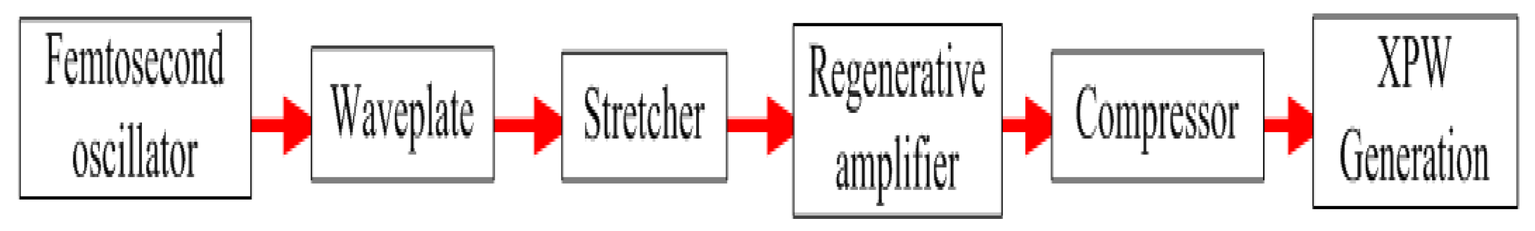
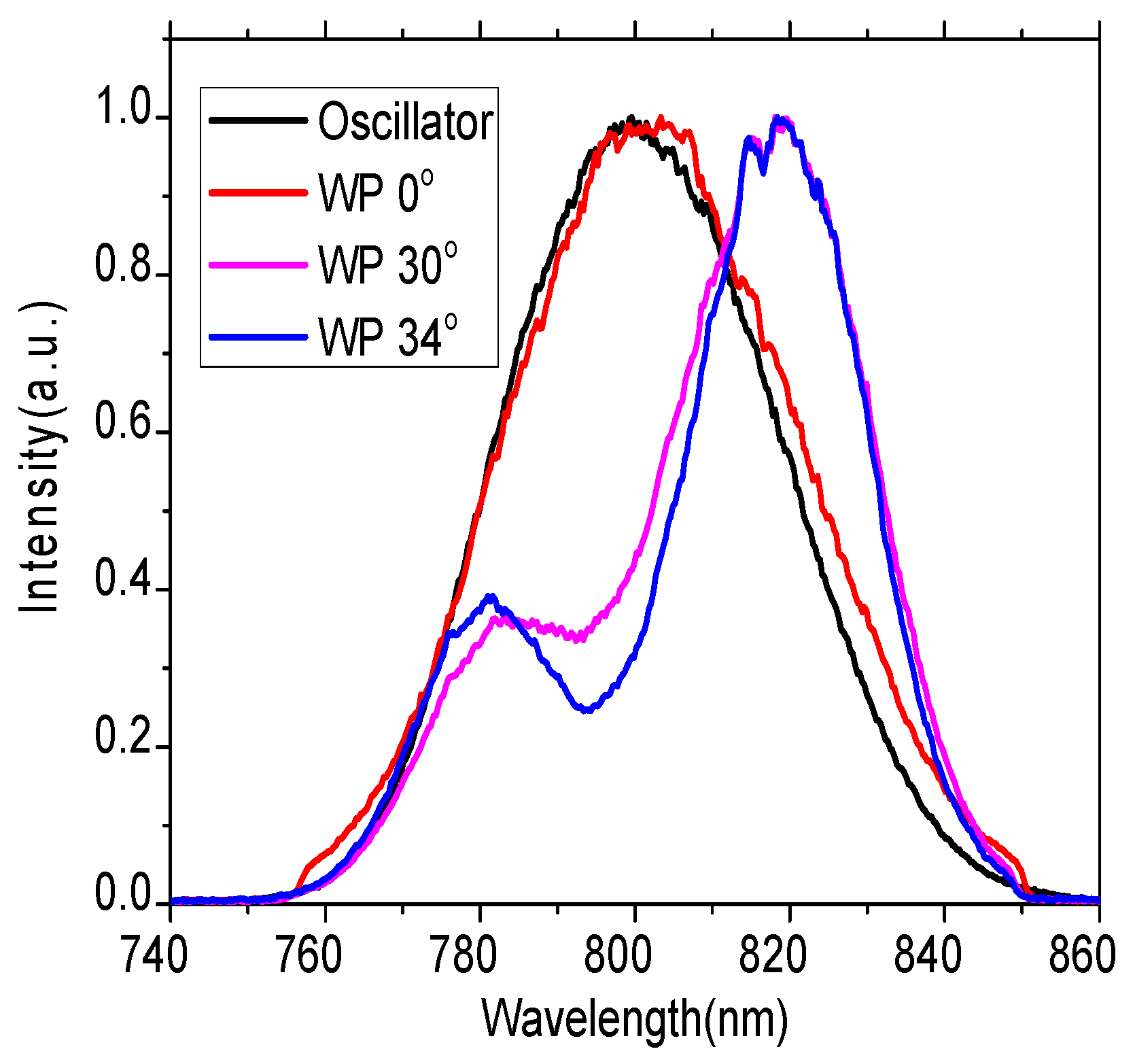
3. Gain Narrowing Pre-Compensating Experimental Setup and Results

In order to reduce the energy loss with the WP and to obtain broadband output spectra, based on the limited 40 nm FWHM bandwidth of the oscillator spectra, we designed and fabricated a 1.117 mm thickness quartz WP, with an anti-reflection coating for both surfaces. This experiment was implemented in an old Spitfire laser (Spectra Physics). The femtosecond oscillator had 40 nm FWHM bandwidth spectrum with 4 nJ and vertical polarization. The fabricated WP was placed at the exit of the oscillator in order to reduce the beam pointing fluctuation effect, as shown in Figure 4. There was a Glan laser polarizer before the Faraday isolator, which was located before the stretcher. Combined with the WP, it removed the unwanted polarization beam, and the energy loss was 50% with a WP rotation angle of 34°. After the seed beam went through the Offner stretcher, it injected into a regenerative amplification. Finally, the amplified beam was compressed with a single grating compressor. In order to prove that this extra-cavity gain narrowing pre-compensating method works well the amplified laser beam, it was attenuated to 220 μJ and was used for XPW generation.
The spectra of the seed beam before the regenerative amplifier were measured with a spectrometer (BWTEK) and are shown in Figure 5 for different rotation angles of the WP. As the rotation angle increases, the attenuation depth of the attenuation curve increases, and the central wavelength of the attenuation curve keeps at 795 nm, which is consistent with the calculated results in Figure 2.
After regenerative amplification, the spectral bandwidths were both 25 nm without the WP or with the WP’s angle of 0°. When the WP rotation angle was rotated to 30°, the amplified spectral bandwidth was 37 nm. When the WP rotation angle was rotated to 34°, the amplified spectral bandwidth was 40 nm, and spectral center had a small dip, as shown in Figure 6. When the rotation angle was turned from 0° to 34°, the seed trips in the regenerative amplification increased by one round, and the amplified beam energy remained the same at 1.5 mJ. As a result of the stable oscillator spectra and good beam pointing stability with the WP at the exit of the oscillator, the amplified spectra remained essentially unaffected for operation for periods of days. After optimizing the compressor, the pulse duration and spectral phase were measured by a Wizzler (Fastlite). A low energy beam was sent to the Wizzler, and the measured pulse duration and the spectral phase are shown in Figure 7, without the WP and with the WP’s angle of 34°, respectively. The FWHM of the measured pulse duration was 42.5 fs without the WP and 33.2 fs with the WP with an angle of 34°, with the same optimized grating incident angle. Residual high-order dispersion from the measured spectral phase was a limitation for the pulse compression, after optimizing the compressor angle. At the same time, we also measured the pulse duration and spectral phase with the WP at an angle of 0°, which was as same as that without the WP. This indicates that the WP worked well for gain narrowing pre-compensation.

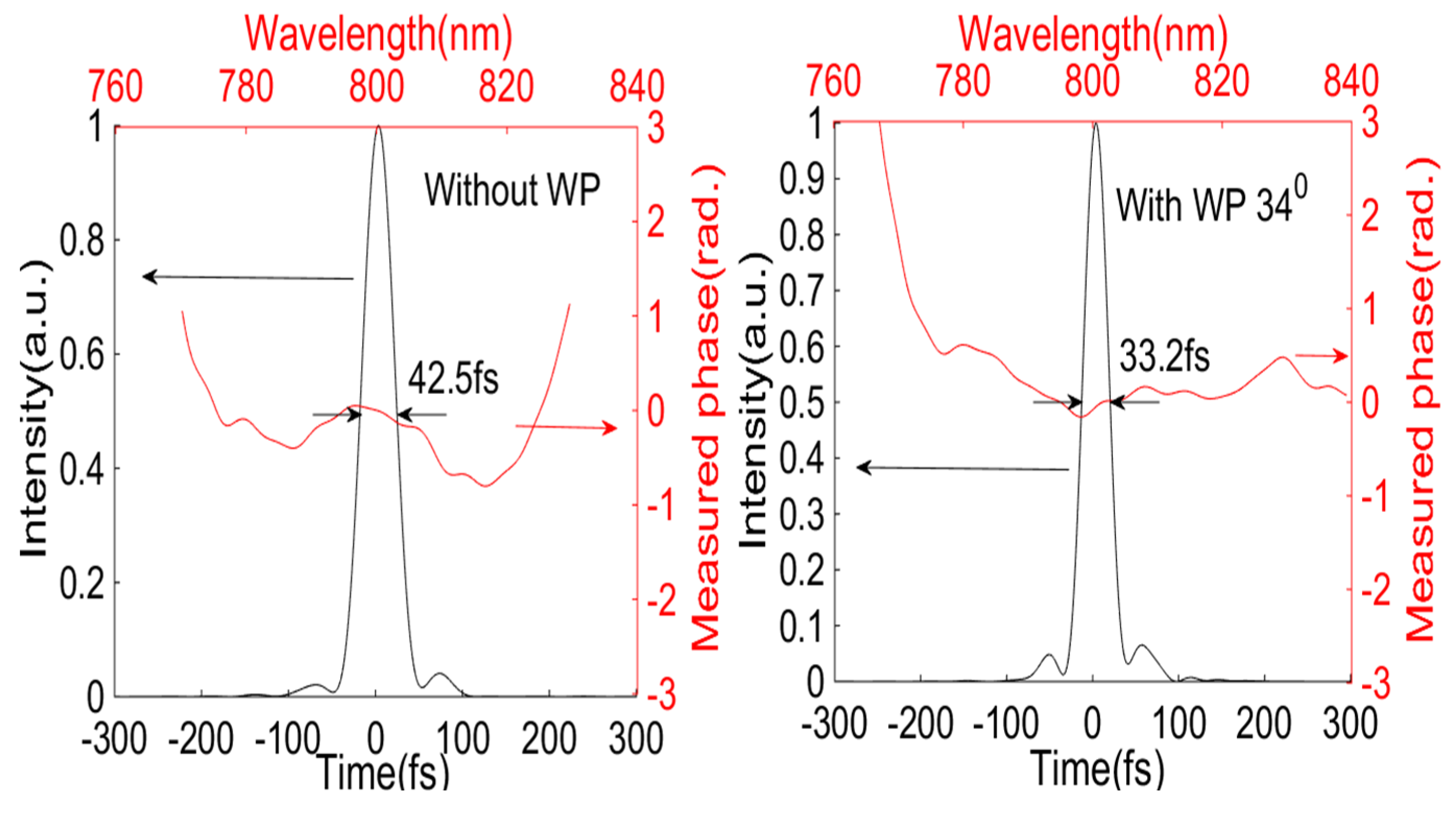
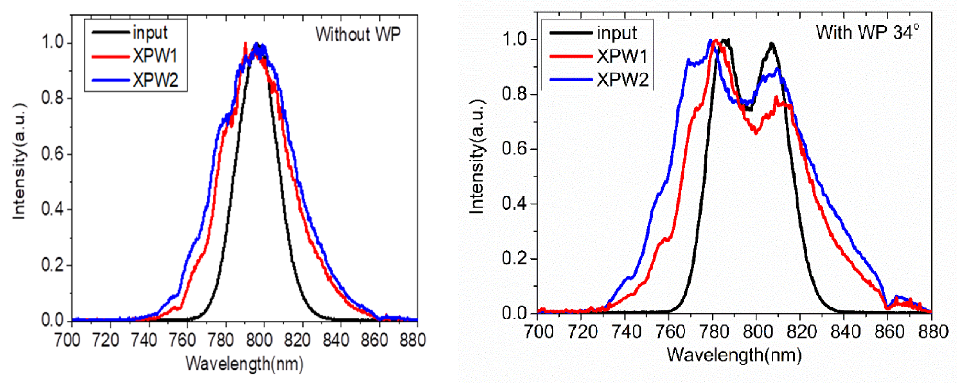
4. XPW Generation Experiment

In order to further examine the gain narrowing pre-compensation effect with the WP, we conducted an XPW generation experiment, and the layout is shown in Figure 8. A zero-order half waveplate was inserted before the compressor of the laser system, and the half waveplate and compressor were combined as an energy attenuator to reduce the output energy to ~250 μJ and to reduce the nonlinear effect in the first Glan laser polarizer of the XPW generation system [22]. Those output pulses went through the XPW generation system. The input beam firstly went through an energy attenuation system, a zero-order half waveplate and a Glan laser polarizer with a diameter of 12 mm in order to finely adjust the input beam energy and to obtain a purely vertical polarization laser beam. Secondly, a Galilean beam reducer, including a concave mirror with f = 1000 mm and a convex mirror with f = −350 mm, was used to focus the input beam in the air. Thirdly, two BaF2 crystals with crystallographic orientations of [011] were both placed after the focal position to generate a high efficiency XPW [23] by optimizing the crystal position, separately. Fourthly, the XPW was collimated with a focal lens f = 1800 mm, and the second Glan laser polarizer was used to eliminate the fundamental beam. Finally, the generated XPW generation was reflected by a 45° ultrafast laser mirror to the spectrometer.
The input laser energy was kept at 220 μJ, and the beam diameter was ~600 µm (at 1/𝑒2 of the intensity profile) at the focal position. Since the XPW conversion efficiency and spectral broadening effect depend on the laser intensity on the BaF2 crystal [24], we chose the same XPW conversion efficiency with BaF2 crystals to test the gain narrowing pre-compensation effect, with the WP at angle of 34° and without the WP. The first BaF2 crystal with a thickness of 1 mm was inserted behind the focal position until the XPW energy reached ~10 μJ (efficiency ~4.6%) to reduce the nonlinear effect and to avoid crystal damage. In addition, the second BaF2 crystal with a thickness of 2 mm was placed behind the first BaF2 crystal, with a total XPW energy of 33 μJ (efficiency 15%) to avoid damaging the crystal. The typical spectra of the input laser beam, the XPW with the 1st BaF2 crystal (XPW1) and the XPW with the 1st and 2nd BaF2 crystals (XPW2) are shown in Figure 9, without the WP and with the WP at an angle of 34°, respectively. The ultrafast reflection mirror supports the wavelength range from ~750 nm to ~850 nm for P-polarization, which induced the measured XPW spectra with the WP at an angle of 34° to have a dip at 860 nm. The FWHM of the generated XPW spectra was 45 nm without the WP, and the XPW spectra broadening was 1.8 times compared with the input spectra of 25 nm. The FWHM of the generated XPW spectra was 68 nm with the WP at an angle of 34°, and the XPW spectra broadening was 1.7 times compared with the input spectra of 40 nm. The XPW spectra was broadened ~1.7 times, which is consistent with normal XPW experiment results [25,26]. The XPW experiment indicated that gain narrowing pre-compensation with a WP works well, as the compressed pulse was close to being transform-limited and was consistent with the measured pulse duration. The much greater broadband XPW with a WP would be a benefit for high-temporal-contrast ultra-fast ultra-intensity laser amplification.

5. Conclusions

A proof-of-principle experiment for gain narrowing pre-compensation with a quartz multi-order triple-wavelength WP was demonstrated, the spectra were broadened from 25 nm to 40 nm and the broadest spectral pulse was compressed to 33.2 fs. As a result of low energy loss, the amplified beam energy was maintained when the WP was inserted in the optical path. As a result of the stable oscillator seed spectra and good beam pointing stability with the WP at the exit of the oscillator, the amplified spectra was maintained for whole days. This simple method can obtain broader output spectra with a broader seed beam. In order to prove that this method works well, an XPW generation experiment was conducted. The generated XPW energy reached 33 μJ with 15% conversion efficiency, and the generated XPW spectra was 68 nm with 40 nm input beam spectra.

Author Contributions

Conceptualization, B.Z.; Validation, B.Z. and X.Z.; Visualization, B.Z., C.L., Q.L., J.Z. and X.M.; Writing—original draft preparation, B.Z., X.Z., C.L., J.Z., X.M., M.M. and G.Y.; Writing—review and editing, B.Z., X.Z., C.L., J.Z., X.M., M.M. and G.Y. All authors have read and agreed to the published version of the manuscript.

Funding

This research was funded by the Continuous Basic Research Project No. WDJC-2019-02, and by the National Natural Science Foundation of China (NSFC) Grant No.12005305.

Institutional Review Board Statement

Not applicable.

Informed Consent Statement

Not applicable.

Data Availability Statement

The data that support the findings of this study are available from the corresponding author upon reasonable request.

Acknowledgments

The authors would like to thank Zhaohua Wang (Institute of Physics, Chinese Academy of Sciences) for helpful discussions in the early stages of the work.

Conflicts of Interest

The authors declare no conflict of interest.

References

  1. Strickland, D.; Mourou, G. Compression of amplified chirped optical pulses. Opt. Commun. 1985, 55, 447–449. [Google Scholar] [CrossRef]
  2. Danson, C.N.; Haefner, C.; Bromage, J.; Butcher, T.; Chanteloup, J.C.-F.; Chowdhury, E.A.; Galvanauskas, A.; Gizzi, L.A.; Hein, J.; Hillier, D.I.; et al. Petawatt and exawatt class lasers worldwide. High Power Laser Sci. Eng. 2019, 7, e54. [Google Scholar] [CrossRef]
  3. Sung, J.H.; Lee, H.W.; Yoo, J.Y.; Yoon, J.W.; Lee, C.W.; Yang, J.M.; Son, Y.J.; Jang, Y.H.; Lee, S.K.; Nam, C.H. 4.2 PW, 20 fs Ti:sapphire laser at 0.1 Hz. Opt. Lett. 2017, 42, 2058–2061. [Google Scholar] [CrossRef]
  4. Zhang, Z.; Wu, F.; Hu, J.; Yang, X.; Gui, J.; Liu, X.; Wang, C.; Liu, Y.; Lu, X.; Xu, Y.; et al. The 1 PW/0.1 Hz laser beamline in SULF facility. High Power Laser Sci. Eng. 2020, 8, e4. [Google Scholar] [CrossRef] [Green Version]
  5. Zeng, X.; Zhou, K.; Zuo, Y.; Zhu, Q.; Su, J.; Wang, X.; Wang, X.; Huang, X.; Jiang, X.; Jiang, D.; et al. Multi-petawatt laser facility fully based on optical parametric chirped-pulse amplification. Opt. Lett. 2017, 42, 2014–2017. [Google Scholar] [CrossRef]
  6. Nakamura, K.; Mao, H.-S.; Gonsalves, A.; Vincenti, H.; Mittelberger, D.E.; Daniels, J.; Magana, A.; Toth, C.; Leemans, W.P. Diagnostics, Control and Performance Parameters for the BELLA High Repetition Rate Petawatt Class Laser. IEEE J. Quantum Electron. 2017, 53, 1–21. [Google Scholar] [CrossRef]
  7. Barty, C.P.J.; Korn, G.; Raksi, F.; Tien, A.-C.; Wilson, K.R.; Yakovlev, V.V.; Rose-Petruck, C.; Squier, J.; Yamakawa, K. Regenerative pulse shaping and amplification of ultrabroadband optical pulses. Opt. Lett. 1996, 21, 219–221. [Google Scholar] [CrossRef] [PubMed]
  8. Bagnoud, V.; Salin, F. Amplifying laser pulses to the terawatt level at a 1-kilohertz repetition rate. Appl. Phys. B 2000, 70, S165–S170. [Google Scholar] [CrossRef]
  9. Leng, Y.; Lin, L.; Wang, W.; Jiang, Y.; Tang, B.; Xu, Z. Broadband spectral shaping in a Ti:sapphire regenerative amplifier. Opt. Laser Technol. 2003, 35, 425. [Google Scholar] [CrossRef]
  10. Lu, X.; Li, C.; Leng, Y.; Wang, C.; Zhang, C.; Liang, X.; Li, R.; Xu, Z. Berefringent plate design for broadband spectral shaping in a Ti:sapphire regenerative amplifier. Chin. Opt. Lett. 2007, 5, 493–496. [Google Scholar]
  11. Takada, H.; Kakehata, M.; Torizuka, K. High-repetition-rate 12fs pulse amplification by a Ti:sapphire regenerative amplifier system. Opt. Lett. 2006, 31, 1145–1147. [Google Scholar] [CrossRef] [PubMed]
  12. Durfee, C.G.; Bera, S.; Sabbah, A.; Squier, J.A.; Ellison, M. Spectral shaping filter for broadband amplifiers. Opt. Commun. 2006, 263, 256–260. [Google Scholar] [CrossRef]
  13. Oksenhendler, T.; Kaplan, D.; Tournois, P.; Greetham, G.; Estable, F. Intracavity acousto-optic programmable gain control for ultra-wide-band regenerative amplifiers. Appl. Phys. B 2006, 83, 491–494. [Google Scholar] [CrossRef]
  14. Zheng, S.; Chen, W.; Cai, Y.; Lu, X.; Zheng, G.; Li, J.; Xu, S. Intra-cavity spectral shaping based on optical rotatory dispersion in a broadband Ti:S regenerative amplifier. Laser Phys. Lett. 2015, 12, 085301. [Google Scholar] [CrossRef]
  15. Zheng, S.; Zeng, X.; Pan, X.; Li, J.; Cai, Y.; Zheng, G.; Xu, S. Enhancing the output bandwidth of a chirped-pulse Ti:S multipass amplifier via optical rotatory dispersion. Opt. Lasers Eng. 2016, 78, 86–90. [Google Scholar] [CrossRef]
  16. Kalashnikov, M.; Cao, H.; Osvay, K.; Chvykov, V. Polarization-encoded chirped pulse amplification in Ti:sapphire: A way toward few-cycle petawatt lasers. Opt. Lett. 2015, 41, 25–28. [Google Scholar] [CrossRef]
  17. Cao, H.; Kalashnikov, M.; Osvay, K.; Khodakovskiy, N.; Nagymihaly, R.S.; Chvykov, V. Active spectral shaping with polarization-encoded Ti:sapphire amplifiers for sub-20 fs multi-terawatt systems. Laser Phys. Lett. 2018, 15, 045003. [Google Scholar] [CrossRef]
  18. Wang, X.; Lu, X.; Liu, Y.; Xu, Y.; Wang, C.; Li, S.; Yu, L.; Liu, X.; Liu, K.; Xu, R.; et al. Broadband spectral shaping in regenerative amplifier based on modified polarization-encoded chirped pulse amplification. Appl. Phys. Express 2018, 11, 062701. [Google Scholar] [CrossRef]
  19. Verluise, F.; Laude, V.; Cheng, Z.; Spielmann, C.; Tournois, P. Amplitude and phase control of ultrashort pulses by use of an acousto-optic programmable dispersive filter: Pulse compression and shaping. Opt. Lett. 2000, 25, 575–577. [Google Scholar] [CrossRef]
  20. Collett, E. Field Guide To Polarization; SPIE Press: Bellingham, WA, USA, 2005. [Google Scholar]
  21. Malitson, I.H. Interspecimen comparison of the refractive index of fused silica. J. Opt. Soc. Am. 1965, 55, 1205–1208. [Google Scholar] [CrossRef]
  22. Zhao, B.; Banerjee, S.; Yan, W.; Zhang, P.; Zhang, J.; Golovin, G.; Liu, C.; Fruhling, C.; Haden, D.; Chen, S.; et al. Control over high peak-power laser light and laser-driven X-rays. Opt. Commun. 2018, 412, 141–145. [Google Scholar] [CrossRef]
  23. Canova, L.; Kourtev, S.; Minkovski, N.; Jullien, A.; Lopez-Martens, R.B.; Albert, O.; Saltiel, S.M. Efficient generation of cross-polarized femtosecond pulses in cubic crystals with holographic cut orientation. Appl. Phys. Lett. 2008, 92, 231102. [Google Scholar] [CrossRef]
  24. Minkovski, N.; Petrov, G.I.; Saltiel, S.M.; Albert, O.; Etchepare, J. Nonlinear polarization rotation and orthogonal polarization generation experienced in a single-beam configuration. J. Opt. Soc. Am. B 2004, 21, 1659–1664. [Google Scholar] [CrossRef]
  25. Jullien, A.; Rousseau, J.-P.; Mercier, B.; Antonucci, L.; Albert, O.; Chériaux, G.; Kourtev, S.; Minkovski, N.; Saltiel, S.M. Highly efficient nonlinear filter for femtosecond pulse contrast enhancement and pulse shortening. Opt. Lett. 2008, 33, 2353–2355. [Google Scholar] [CrossRef] [PubMed]
  26. Ricci, A.; Jullien, A.; Rousseau, J.-P.; Liu, Y.; Houard, A.; Ramírez, P.; Papadopoulos, D.; Pellegrina, A.; Georges, P.; Druon, F.; et al. Energy-scalable temporal cleaning device for femtosecond laser pulses based on cross-polarized wave generation. Rev. Sci. Instrum. 2013, 84, 043106. [Google Scholar] [CrossRef] [PubMed] [Green Version]
Figure 1. The transmittance spectra for different optimized WP thicknesses and rotation angle of 45°. Notice that it is a half WP for 795 nm.
Applsci 12 05521 g001
Figure 2. The transmittance spectra of a 1.117 mm thickness WP for different rotation angles.
Applsci 12 05521 g002
Figure 3. The transmittance spectra for different thicknesses of WPs around 1.117 mm and with a rotation angle of 45°.
Applsci 12 05521 g003
Figure 4. The outline of the experimental setup of gain compensating and XPW generation.
Applsci 12 05521 g004
Figure 5. The spectra of the oscillator and the spectra of the seed beam before the regenerative amplifier for different rotation angles of the WP.
Applsci 12 05521 g005
Figure 6. The spectra of the amplified beam for different rotation angles of the WP.
Applsci 12 05521 g006
Figure 7. The measured pulse duration and spectral phase after optimizing the compressor, without WP and with WP at an angle of 34°.
Applsci 12 05521 g007
Figure 8. The layout of the XPW generation system with two BaF2 crystals in the air. HWP is the zero-order half waveplate, and M1 and M2 are 45° reflection ultrafast laser mirrors.
Applsci 12 05521 g008
Figure 9. Typical spectra of the input laser beam, XPW with 1st BaF2 crystal (XPW1) and XPW with 1st and 2nd BaF2 crystals (XPW2), under the condition of being without the WP and being with the WP at an angle of 34°.
Applsci 12 05521 g009
Publisher’s Note: MDPI stays neutral with regard to jurisdictional claims in published maps and institutional affiliations.

