3.1. Protection Criterion
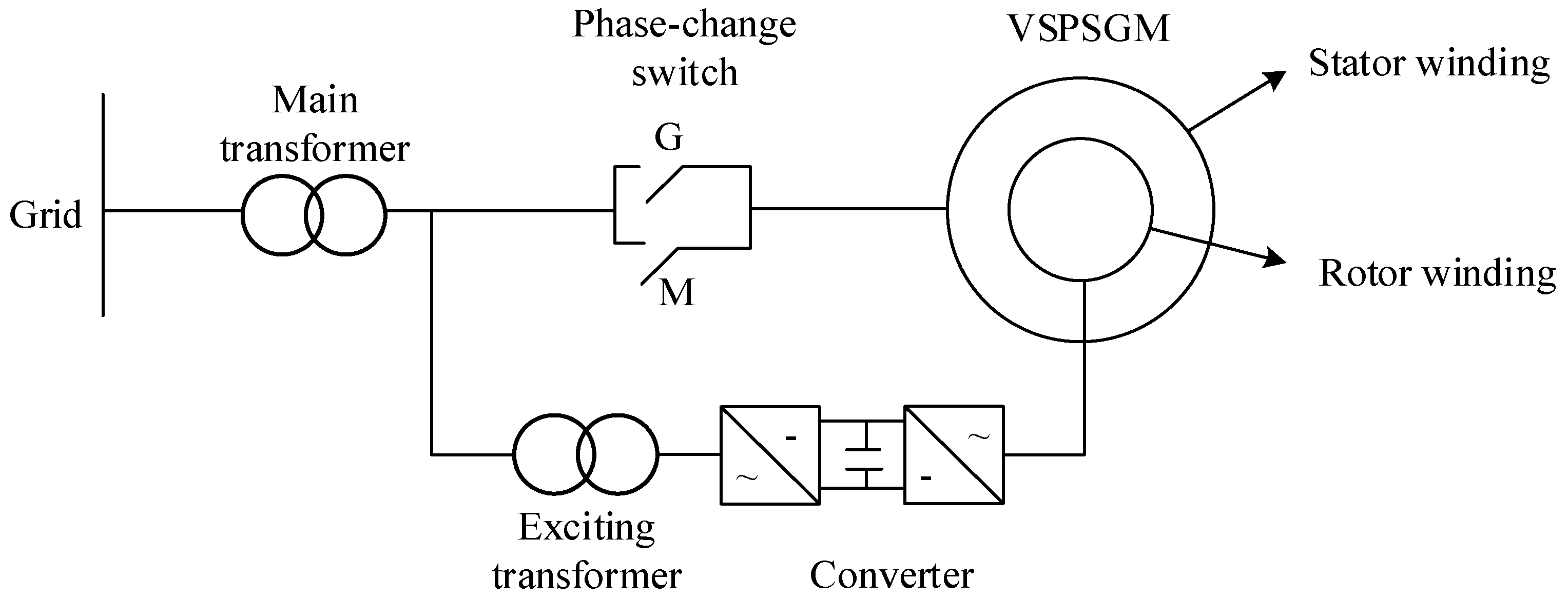
Taking the VSPSGM of Hebei Fengning Pumped Storage Power Station as an example, its capacity is 300 MW; the pole-pairs number is 7; the rated speed is 428.6 r/min; the rotor speed range is −10%~+10%; and the power factor is 0.9. Other parameters of the VSPSGM are shown in
Table 1 [
16]. The mathematical analytical simulation model is established based on the multiloop method [
20]:
where
p is a differential operator;
Us and
Ur are the branch voltage matrices of the stator and rotor, respectively;
Is and
Ir are the branch current matrices of the stator and rotor, respectively;
Rs and
Rr are the branch resistance matrices of the stator and rotor, respectively [
21].
Lss is the stator inductance matrix,
Lrr is the rotor inductance matrix,
Lsr and
Lrs are the mutual inductance matrices of the stator and rotor [
22]. The detailed calculation process of each parameter is shown in [
23]. Equation (17) is a time-varying ordinary differential equation system, which can be solved by the fourth-order Runge–Kutta algorithm [
24].
When the slip ratio
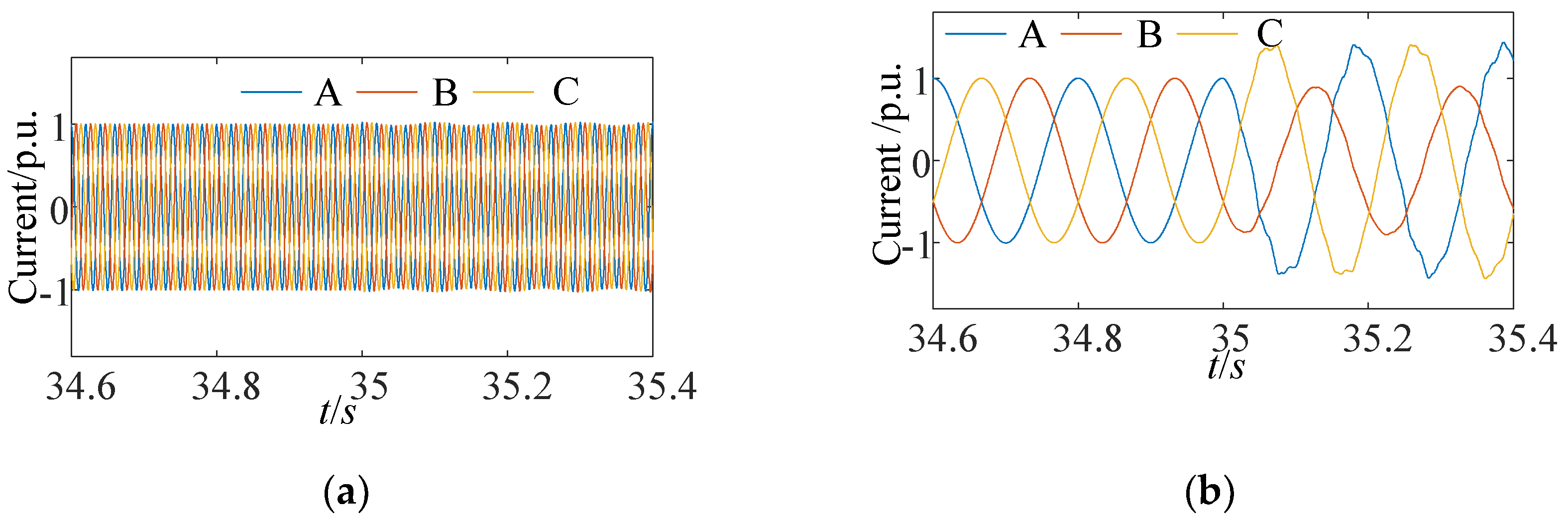
s is 0.1, it is assumed that a short-circuit fault occurs between the 11th coil of the first branch of Phase A and the 8th coil of the second branch of Phase A. The coil turn difference is 3 and the fault time is 35 s. Through simulation calculation, the instantaneous waveform of stator and rotor three-phase currents are obtained, as shown in
Figure 2a,b, respectively. After the fault, the stator three-phase current is dominated by fundamental frequency, containing a small amount of 1 ± 2
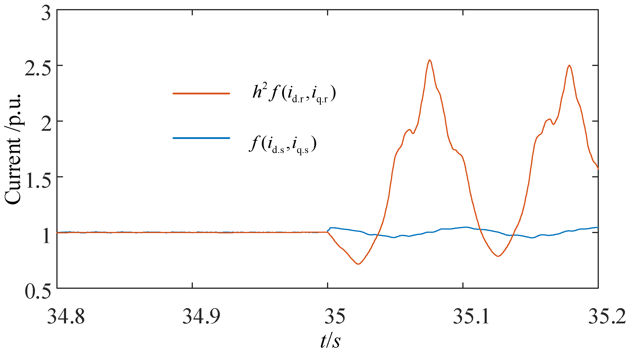
s harmonic components, and the rotor three-phase current changes greatly. The
and
obtained by the Clark transformation are shown in
Figure 3. The current values in the figure are both per-unit values. The reference value is the peak current of the stator phase.
The simulation results in
Figure 3 are consistent with the analysis results. After the fault occurs,
and
have large differences. However, the protection cannot simply use whether the difference between the two
is greater than a certain value as the basis for judging whether the rotor winding short-circuit fault occurs. There are two reasons: (1)
will change dramatically over time, and the protection setting value is difficult to set; (2) in normal operation, if there is a large measurement error in the current measurement value,
at that time may be too large, resulting in protection misoperation.
Aiming at the above problem, it is proposed to judge whether the fault occurs according to the size of the area around
and
. To ensure the rapidity of the protection, the selected area calculation time window is 0.02 s (one power frequency cycle). The stator phase current of the VSPSGM is measured by the electromagnetic current transformer, and the rotor phase current is measured by Hall effect or optical current transformer. Both of them are synchronously measured and the sampling rate is consistent. One power frequency cycle is sampled
N+1 times. In a power frequency cycle,
g[1],
g[2], …,
g[
N+1] can be obtained by the difference between
and
. The area calculated by the trapezoidal rule is:
Furthermore, the protection criterion can be expressed as:
where
is the protection action value,
is the protection setting value. To ensure the reliability of the proposed protection method, the protection setting value should avoid the maximum action value
of the VSPSGM under normal operation.
The steps of the proposed method are as follows:
- (1)
The instantaneous values of the three-phase stator and rotor currents are measured synchronously, and the dq-axis stator and rotor currents are obtained by using the Clark transform. This process is the product operation of the three-dimensional matrix, the computational burden is small, and can be realized quickly.
- (2)
According to Equations (12), (15) and (16), is calculated by using the dq-axis stator and rotor currents, which is no longer equal to 0 after a rotor winding short-circuit fault occurs. This process is a simple algebraic operation; the computational burden is small and can be realized quickly.
- (3)
The protection action value is calculated according to Equation (18), and the protection outlet mode is determined according to the size of the protection action value. This process requires the protection device to have a memory storage function, which is easy to implement. The existing protection device can store the intermediate calculation results in RAM, and can quickly exchange data with the CPU. Thus, the protection action value in Equation (18) can be obtained quickly by invoking the stored results. In addition, this process is a discrete integral operation, its algorithm is not complicated and can be realized quickly.
In summary, the computational burdens of the proposed method are small, and the conventional protection device can realize its function.
3.2. Calculation Method of the Protection Setting Value
The actual VSPSGM may have a slight negative-sequence component in normal operation [
25], which is mainly caused by the structural asymmetry, unbalanced voltage, and sensor measurement error, so the
is not exactly 0. Considering that the VSPSGM will undergo strict performance index detection before leaving the factory, the negative-sequence component generated by structural asymmetry is much smaller than that generated by a large unbalanced voltage. Therefore, the influence of unbalanced voltage and sensor measurement error is mainly considered in the protection setting value calculation. The influence of unbalanced voltage is simulated by the random voltage drop of stator and rotor single-phase voltage, and the influence of the sensor measurement error factor is simulated by adding noise to each phase current obtained by simulation. The maximum action value
under normal operating conditions is simulated and multiplied by the reliability coefficient greater than 1 to obtain the protection setting
.
Taking the VSPSGM shown in
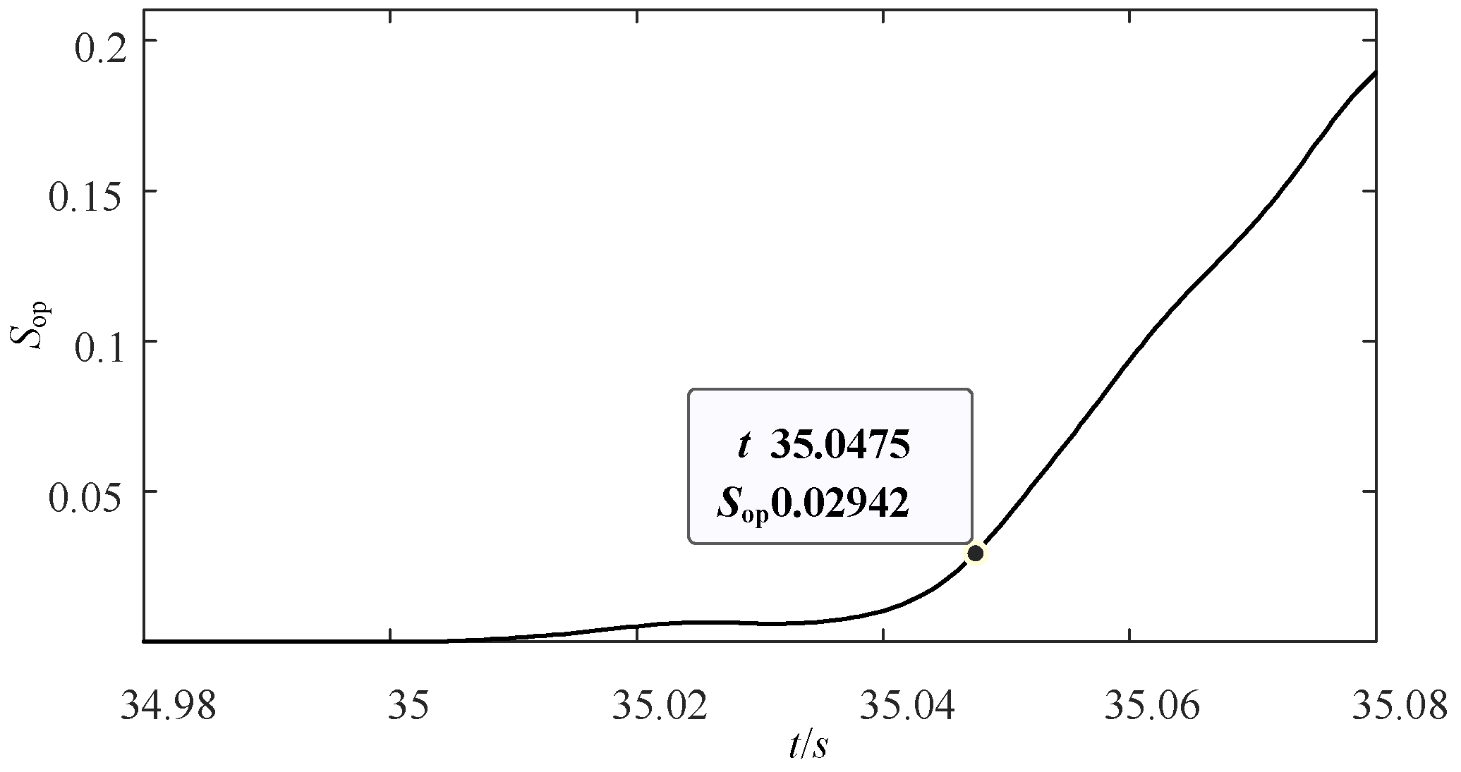
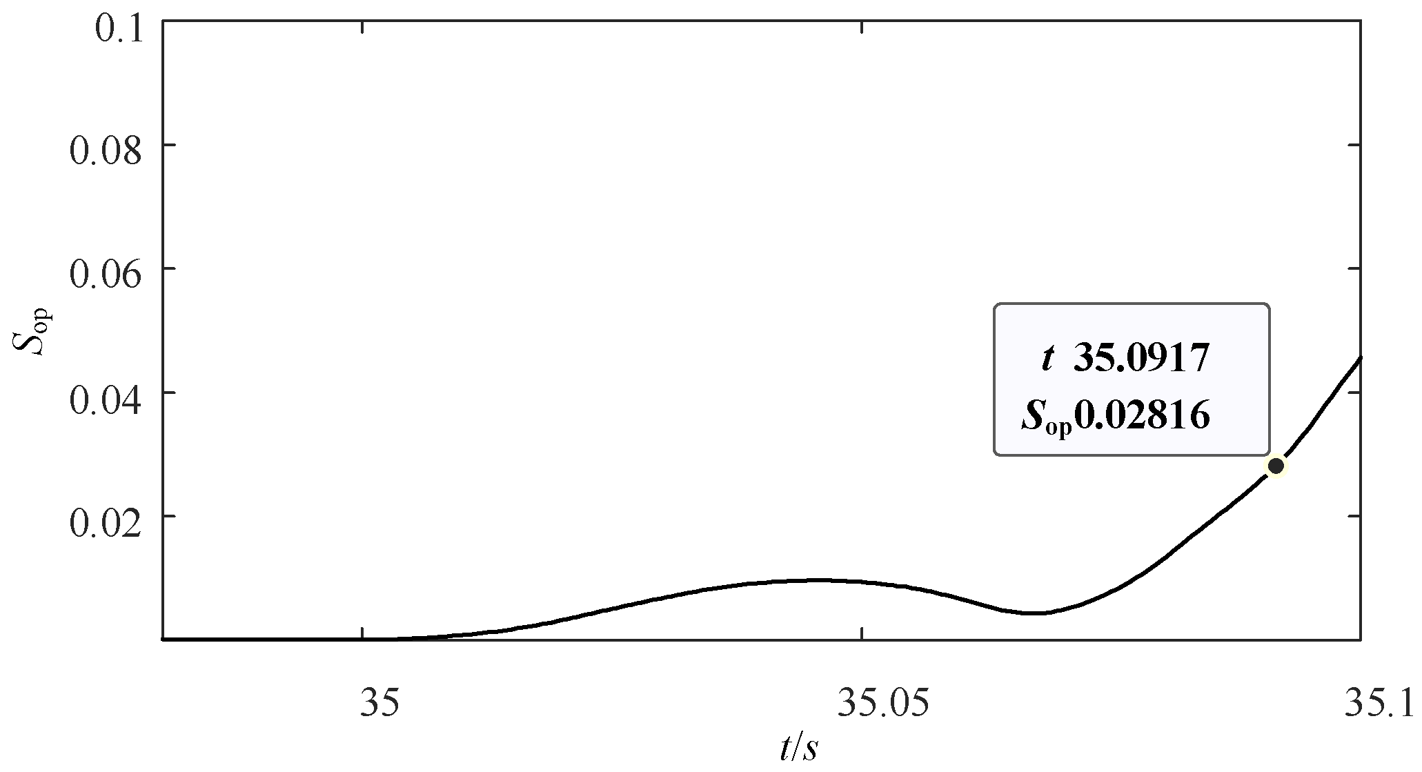
Table 1 as an example, it is assumed that the single-phase voltage of the stator side drops by 1~40% randomly, and the single-phase voltage of the rotor side also drops by 1~40% randomly. A large unbalanced voltage will lead to zero-sequence voltage protection action, so the more serious voltage drop is not considered. A total of 10 dB Gaussian white noise is added to the simulated phase currents. When the slip ratio
s is 0.01, the maximum action value of the normal running state
obtained in the above scenarios is shown in
Figure 4. It can be found that when the voltage drops on the stator and rotor sides, the unbalanced voltage generated will increase the protection action value
, and the maximum value of
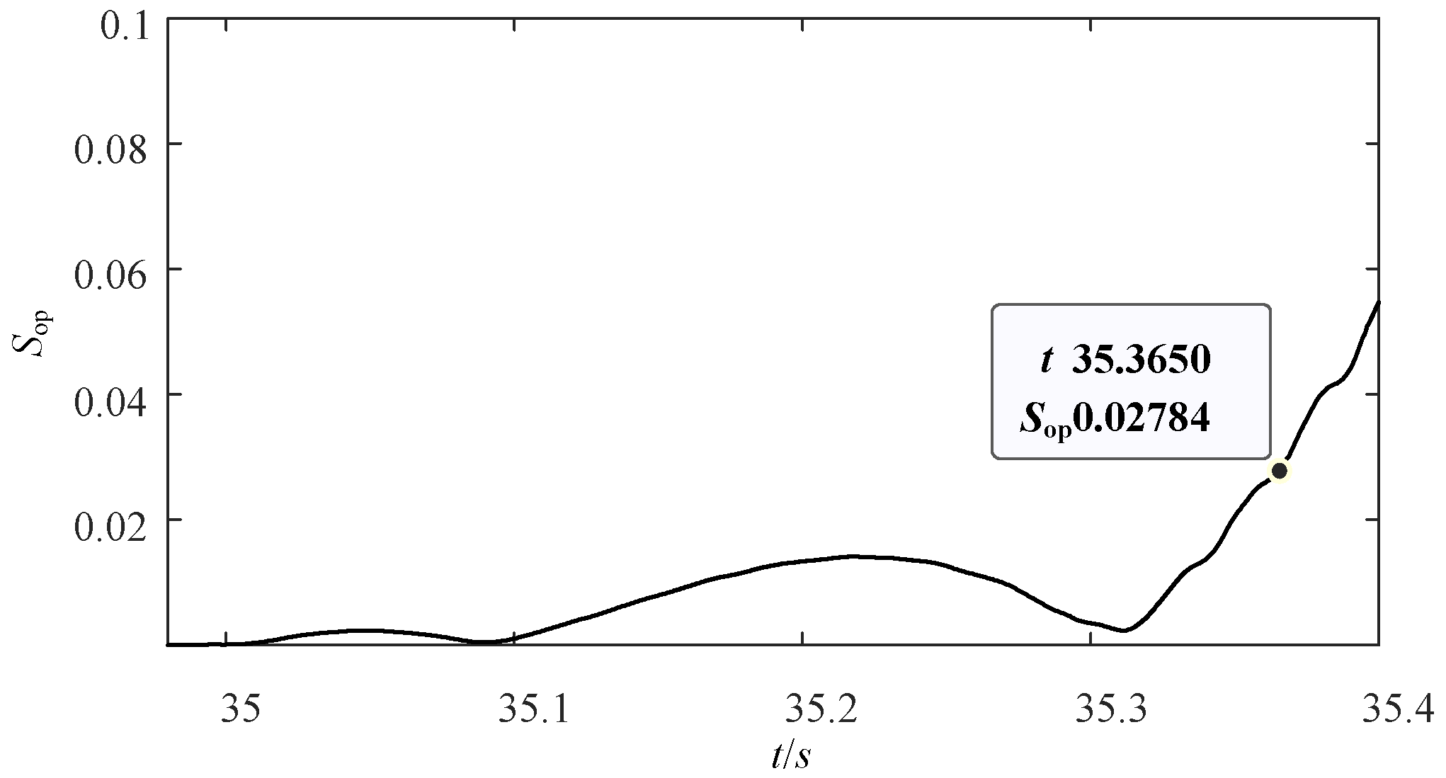
in each scenario is 0.0184. When
s is 0.1, the protection action value
in each scenario is shown in
Figure 5, and the maximum value of
is 0.0179. It can be found that under different rotor speeds, the difference of the maximum action value
caused by unbalanced voltage and sensor measurement error is small, and it can be considered that the maximum
is almost unaffected by the rotor speed. The maximum value is selected to set the protection setting value
.
After the above analysis,
can be set to:
where
is the reliability coefficient. To give the protection setting value
high reliability, the value of
is set as 1.5. Then, the protection setting value
is calculated to be 0.0276.
It should be noted that this method is applicable to VSPSGMs of different types, different capacities, and different winding connection forms. Of course, the protection setting values of different units are different, which need to be set according to their specific parameters, but the calculation method of protection setting values in
Section 3.2 is universal. More specifically, the proposed method can be extended to the motor with three-phase AC excitation, and cannot be applied to the motor with single-phase DC excitation.


 ,
, 


