3.1. Creation of Model
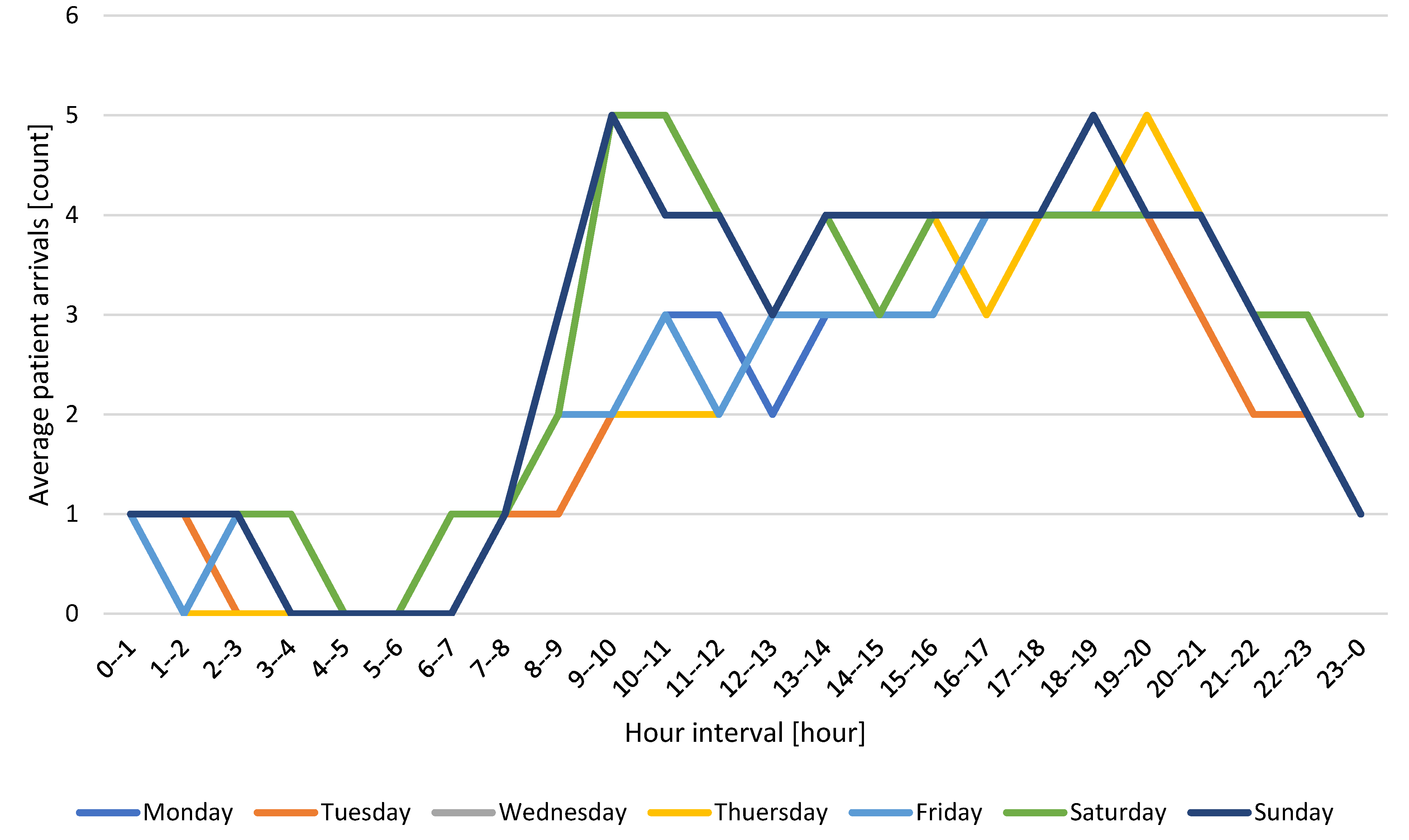
The procedure was applied to the experimental definition of the number of disinfectant AGVs for urgent reception in Zilina, Slovakia, to validate the proposed system. The simulation model, as well as simulation runs, are realised in Siemens’s Tecnomatix Plant Simulation 16 software. The processor used for computing power was an Intel(R) Core (TM) i9-10850K CPU @ 3.60 GHz with 16 GB RAM and a Nvidia t1000 4 GB graphics card, with each thread performing 20 simulation runs at a time. The simulation model itself was created in Tecnomatix Plant Simulation 16 software, which allows the definition of logic through the programming language SimTalk 2.0. Step B1 included the creation of walls and pillars and a drawing area that AGVs could not visit. Within step B2, a 24-h format was established in which doctors and nurses worked. For the model within step B3, patients’ inputs to the system were defined as listed in
Figure 6. Within step B4, patients’ logic is derived from them (
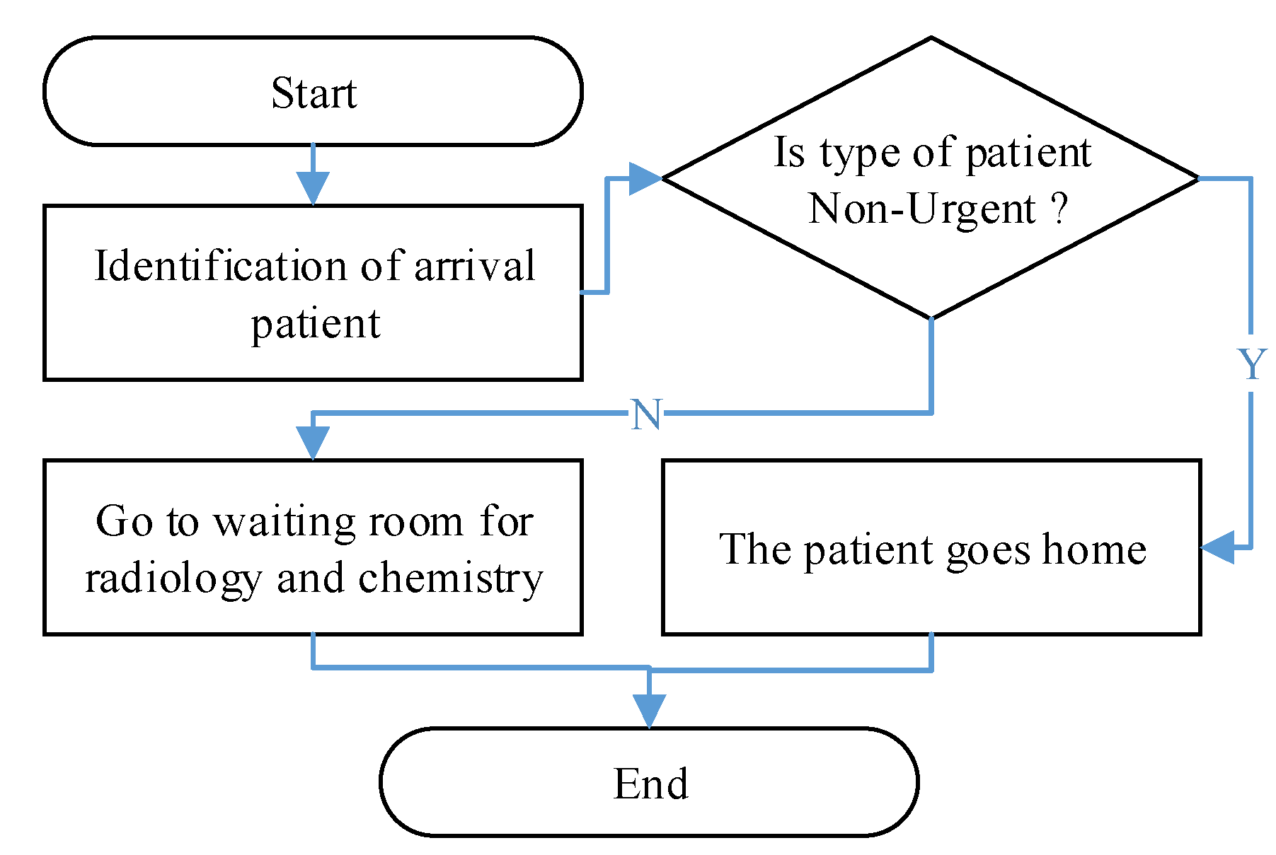
Table 1), and the percentage of their incidence is defined by the target destinations in B5. On this basis, the movement of patients can be defined as B6. The decision-making nodes then collect the data used by the disinfectant AGV (B7). The final layout is displayed in
Figure 7, and an example of the logic of patient decision making at the exit of the surgical ambulance is schematically shown in
Figure 8.
The symbols and colours on the layout represent the following objects: turquoise represents the walls that divide the space, the red hatched part represents rooms where disinfection is not carried out by the AGV, green marks the points where data are collected about the patient’s presence, and red points represent places where the activity is carried out, for example, registration, treatment, and other actions. The blue lines represent the connectors and represent the direction of movement of the patients.
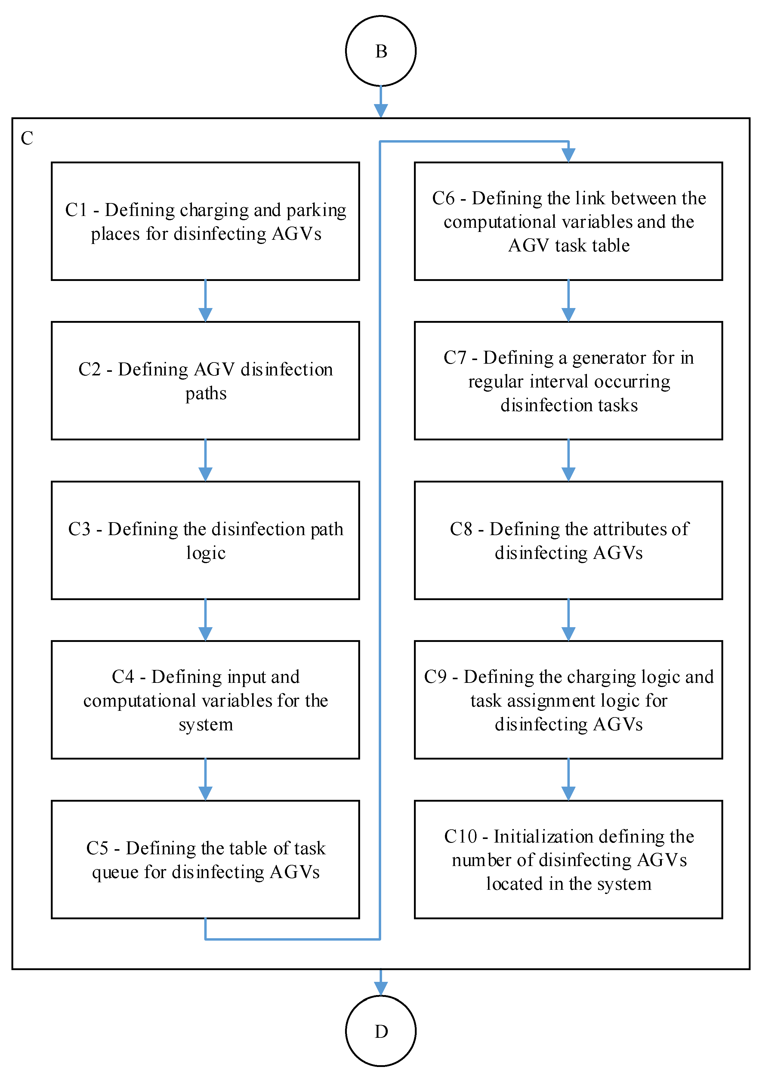
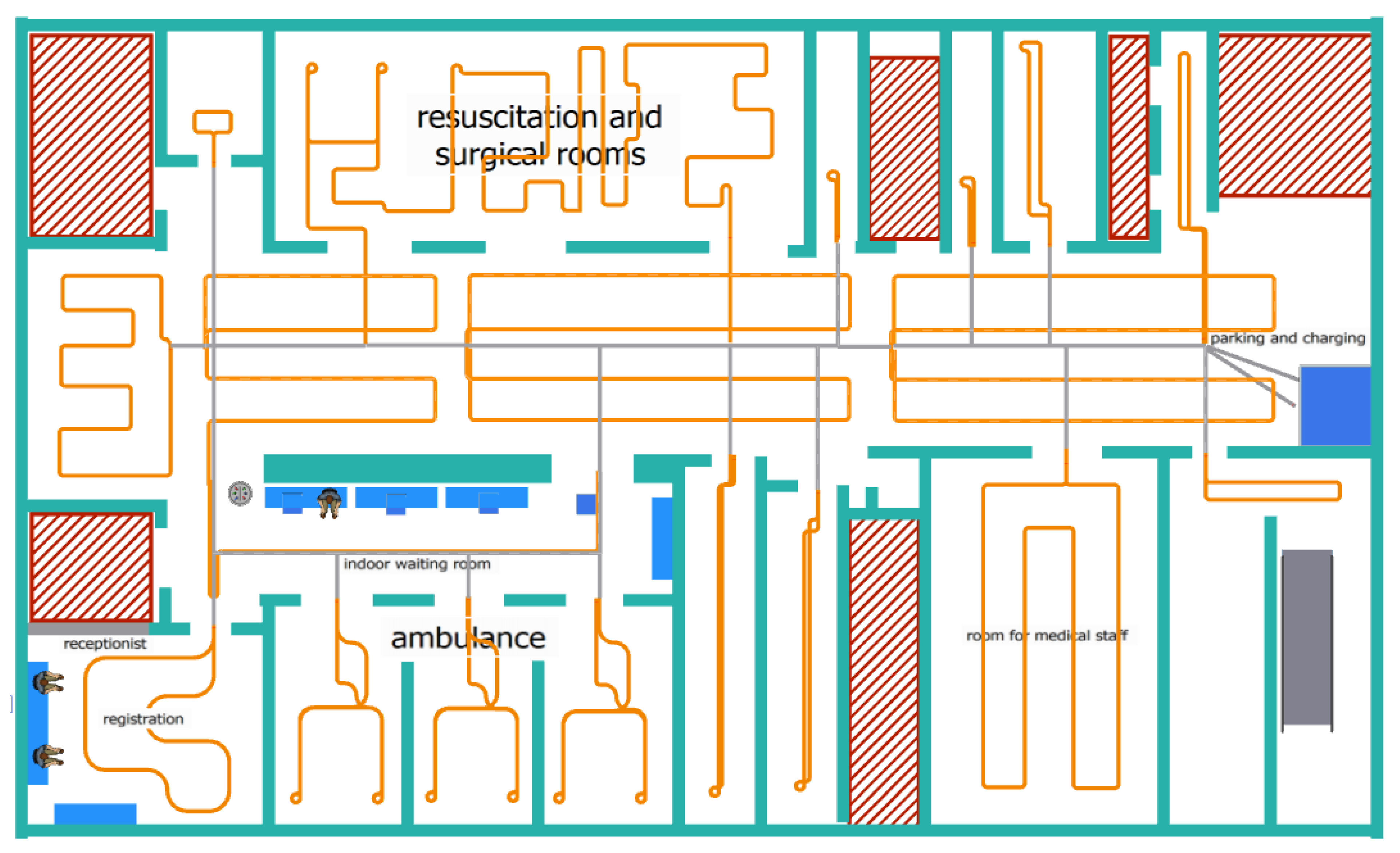
In the simulation model within step C1, one location was determined as the main charging point where the AGV was charged. In this place, the AGV stayed whenever it did not have a defined task or when the battery level fell below the specified reserve value. Within step C1, based on the spatial constraints defined in B1 (for example, ambulation or hall) and the characteristics of the disinfection superstructure that have been set, model 1 m has been established as an effective reach zone for carrying out disinfection tasks (
Figure 9).
The symbols and colours on the layout represent the following objects: turquoise represents the walls dividing the space, the red hatched part represents the rooms where disinfection is not carried out by AGV, the grey lines are the access routes of the disinfection ground AGV along which movement is possible in both directions, and the orange lines are the individual disinfection routes, which are unidirectional.
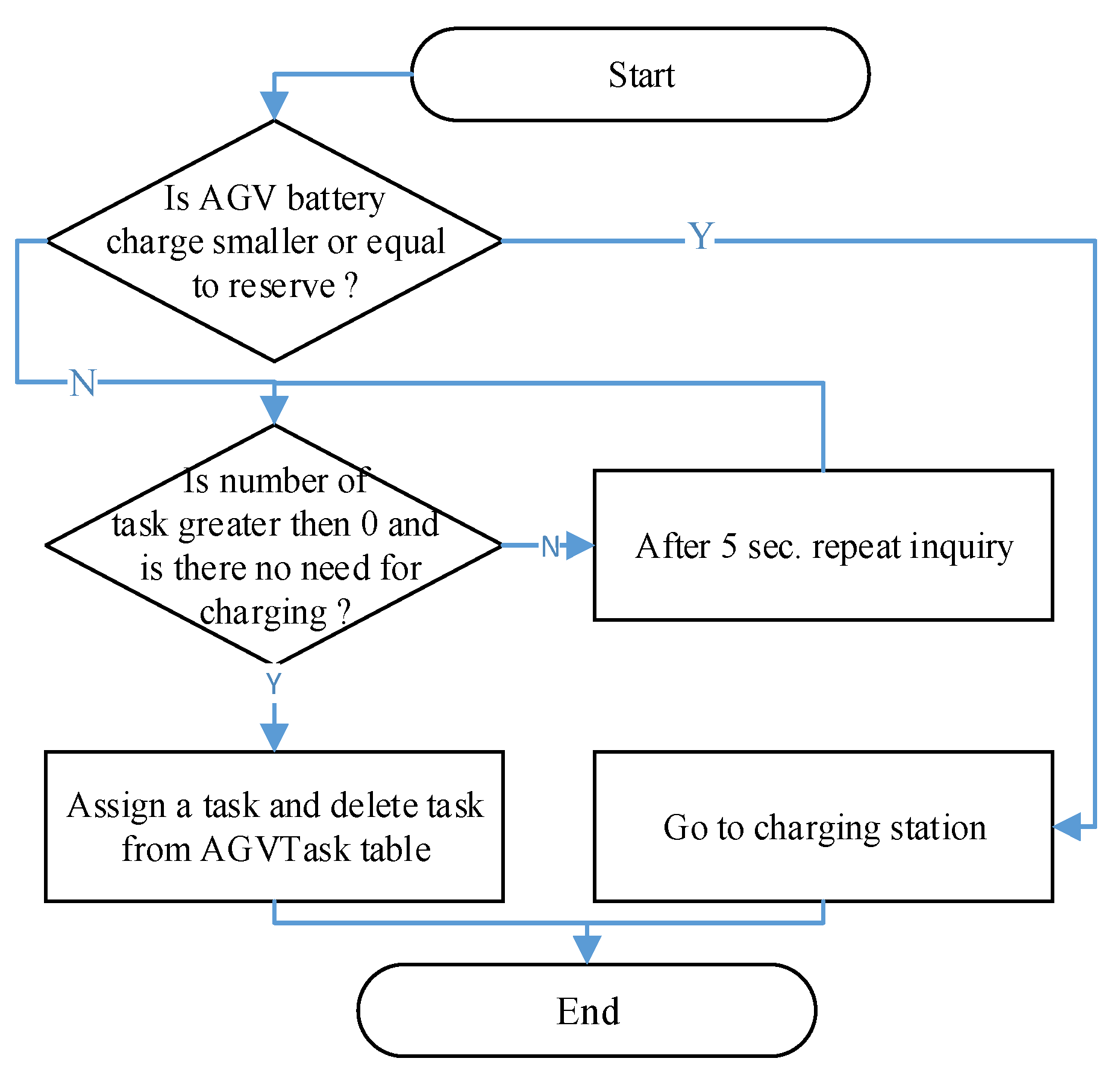
The basic logic of the path was to control the possibility of assigning another task if there was no AGV task in the queue. The AGV returned to the parking place. If the task is in the queue, the AGV starts performing it and indicates that it is being performed. If the battery level is insufficient, the AGV returns to the charging station (
Figure 10).
Within step C4, multiple variables must work in the system to help with calculations and decision making (e.g., area of possible contamination or number of patients and their length of stay). There is a table in the model that records all C5 tasks called AGVTask. If the task starts to be performed, it is deleted from this queue, and the next task comes first. In the case of premises from dynamically generated tasks, the following prioritisation works for assigning the task: surgical 1, outpatient doctors 2, waiting room 3, and reception 4. Other tasks are not prioritised and are written according to the time of generation. Within step C6, generally, all variables are linked to be updated through calculation through methods and event triggers that are triggered based on the nature of the variable (for example, the Reception Number of Patients variable is updated with each output and input to the reception location). Some variables are static and change manually, for example, the point weight for patient arrival (Patient Arrive Weight) and staying in the system for a minute (Patient Stay Weight for Minute). The level of possible contamination is calculated from the number of inputs to the location having a point value of 7 and a minute’s stay in the location, which has a value of 1. An example of the calculation is if two people came in and the second patient was in the system for 10 min, then the calculation is 2 × 7 + 1 × 10. For circuits where regular disinfection occurs, generators are used to run a method that writes tasks to the task queue C7. If it is a dynamic circuit, a calculation is carried out that checks the level of possible contamination in the monitored locations. If it reaches the critical level set at 50, the task is entered into the task queue. Within step C8, the setting of the AGV battery attributes begin.
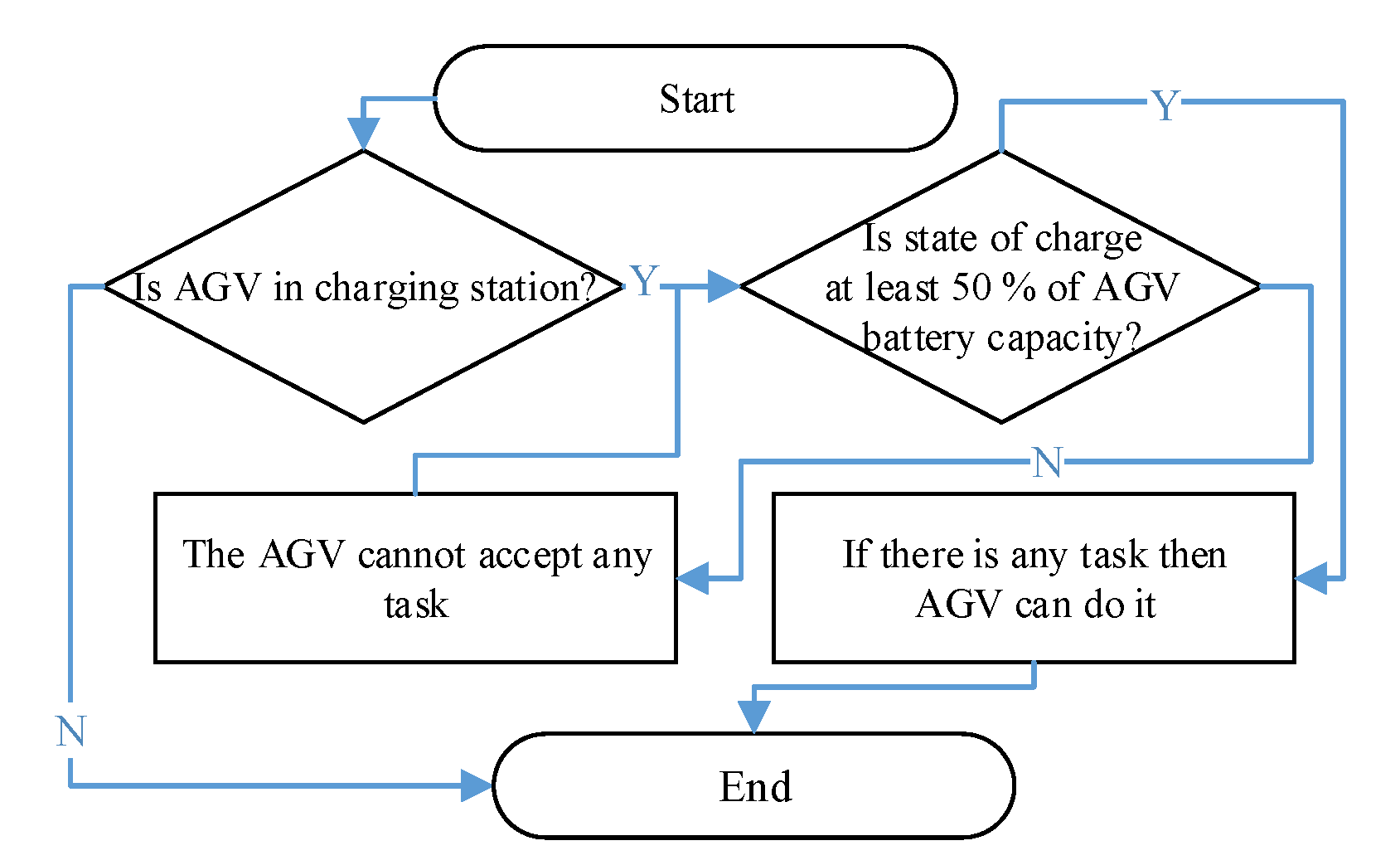
The charging logic within step C9 is defined so that the battery level never slips below the critical reserve limit, which in our case is 60 Ah (
Figure 11). In the charging process, when charging after reaching the reserve, the AGV can then leave charging if it is necessary to perform the task only when the battery charge level is 50% of its total capacity.
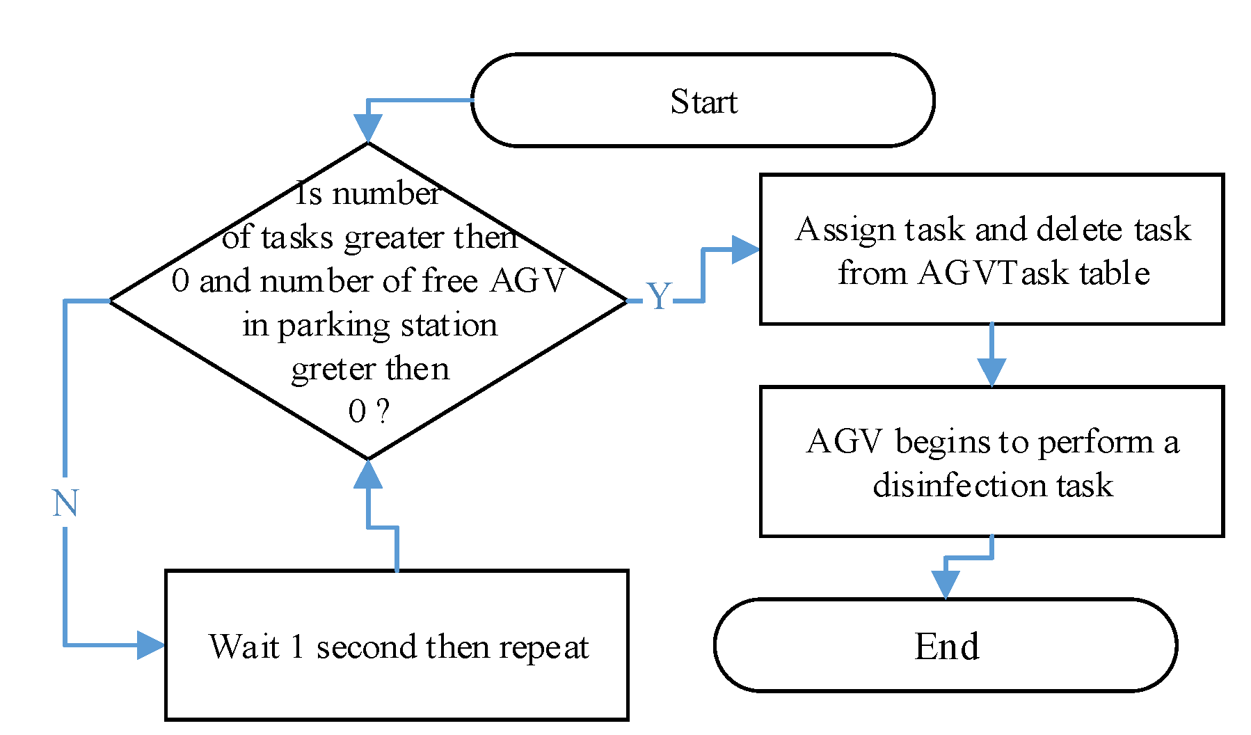
The assignment of a task to an AGV located at the parking/charging place is carried out on the basis of rules on whether the AGV is charging and, at the same time, whether there is a task in the task queue (
Figure 12).
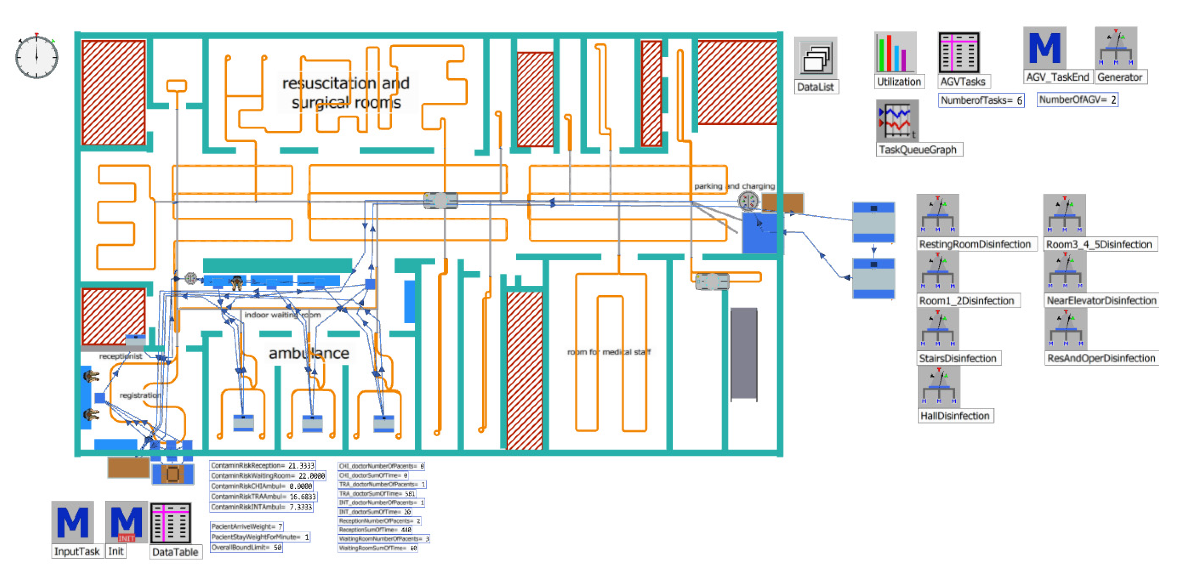
The last step of the block is to define the initialisation number of AGV disinfection units (C10) that will be used for the verification and validation of the entire model (D1). Because the AGV system is not implemented, a portion of the logic of patients is verified and validated. The AGV design is verified to comply with the proposed logic. The simulation model after verification and validation is shown in
Figure 13.
Figure 13 represents the combination of
Figure 7 and
Figure 9 in one dynamic model. The other objects are Tecnomatix Plant Simulation software objects that create the overall logic of the model (for example, methods containing the program, tables, generators, and variables).
In our case, Step D2 defines the number of experiments: there are 20 experiments with 30 repetitions, where the first five experiments consist of testing one to five AGV with an assumed distribution of the number of incoming patients derived from historical data. Thus, the second group of experiments, six to ten, tested the location of one to five disinfectant AGVs with an increased patient input of two per hour. In both cases, AGV could enter the area even if there were patients or during treatment. Experiments 11 to 20 consisted of integrating a rule where the disinfectant AGV could enter the area only when no patient was there. The first five experiments, with the expected distribution of patients, entered the system over time, and the last five experiments had an increased number of patients of two for an hour. The verification itself was carried out for a period of 28 days.
3.2. Experiment Results
Table 2 and
Table 3 show statistics on the use of the disinfection AGV as well as the average number of tasks waiting to be completed each minute. Statistics for the estimation errors of the realised simulation experiments are shown in
Table 4 and
Table 5. The graphical representation is shown in
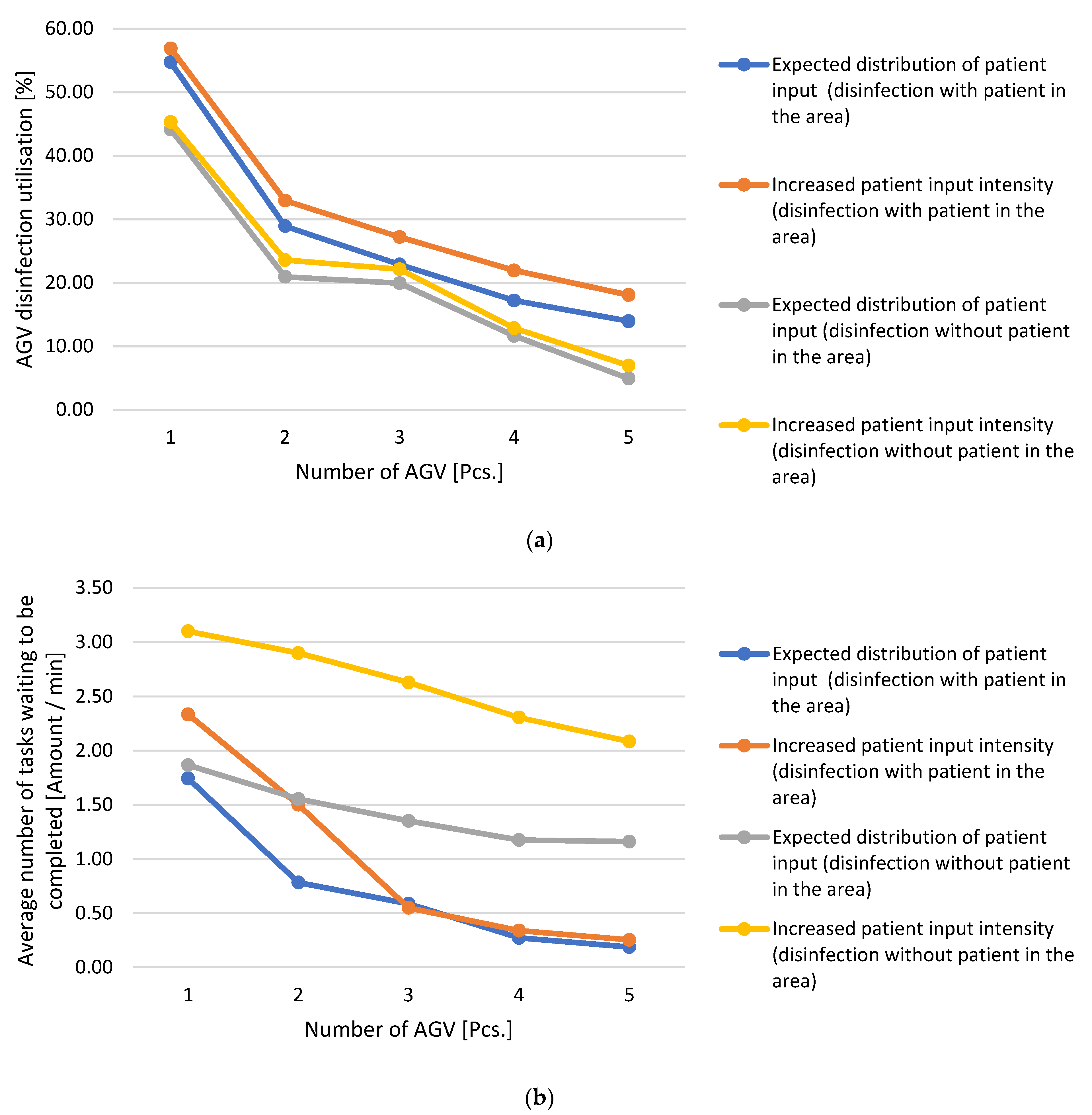
Figure 14.
From the results of the experiments shown in
Figure 13a,b, the following findings can be stated: if a case with the expected distribution of patients is considered without a limitation that is based on patient movement, it can be observed that with the increasing number of disinfection AGVs, the average number of waiting tasks and AGV utilisation decreases. The most significant downward shift for both parameters was between using one and two disinfection AGVs. The decrease is smaller when using two or more AGVs, and when adding more AGVs, the decrease in utilisation and the number of waiting tasks are roughly the same. This is due to the fact that the AGV that completed its task and asked for the next one was always closer than the AGV that parked at the charging point and accepted the task. As a result, the AGVs that were at the charging point were not used and only left when several tasks entered the queue at once or the inquiring, returning AGV did not have a sufficient battery level.
In the case of an increase in patient input intensity without limiting the movement of patients, the same effect was also visible. The development was the same, and the different values were mainly due to the higher number of generated tasks derived from the higher movement of patients around the space.
In experiments involving the condition that no patient should be near an AGV in the disinfection area, it was observed that the average number of tasks was affected by the fact that even if an AGV was free, it could not enter the area. This reduced AGV utilisation; for the average number of tasks, this was probably the most noticeable fact. The AGVs, therefore, waited for the space to be emptied, which was reflected in the parameters, and even a higher number of AGVs could not increase it.
When the patient input intensity increased, the periods without patients were shortened, which worsened both parameters, even though the difference in the expected patient entry in terms of utilisation was not as visible as the number of pending tasks.
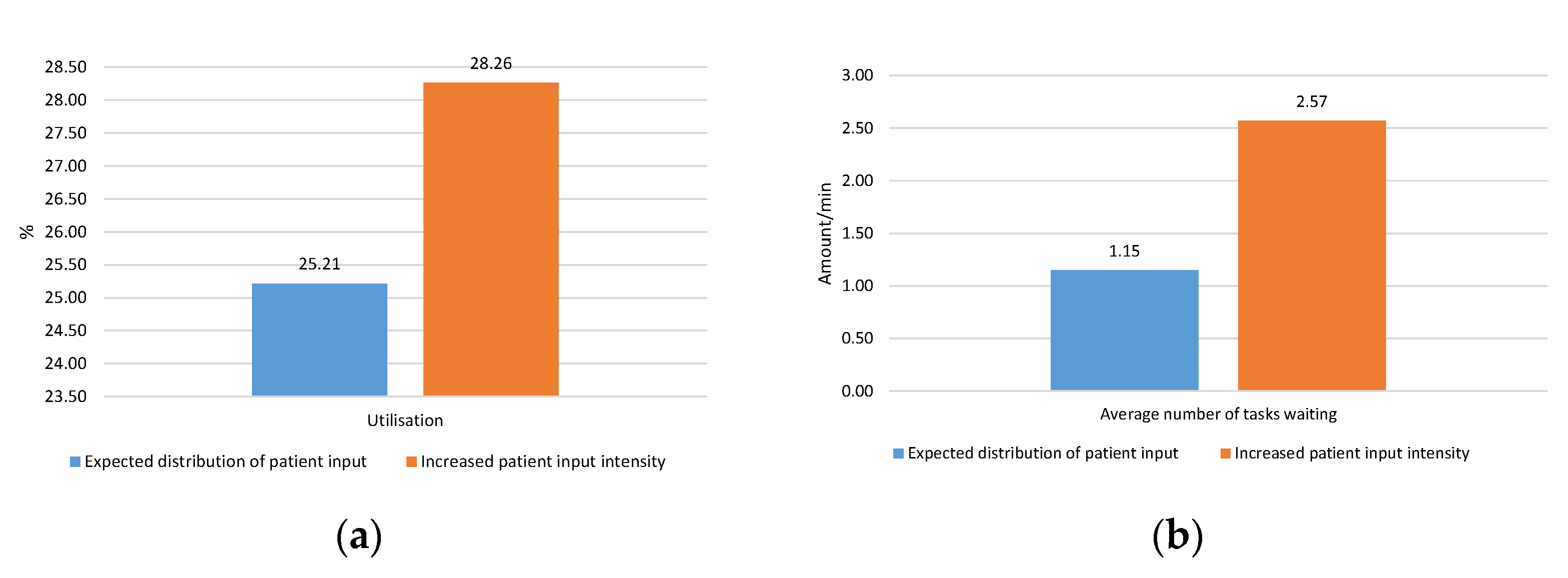
Only one AGV would be ideal in terms of utilisation, but it is insufficient for the waiting task indicator. Because multiple tasks can be generated dynamically at times, and there may be a period without generated tasks or a waiting period for entry into the area for disinfection, the utilisation is significantly affected. Therefore, based on the results, an experiment was carried out in which two disinfectant AGVs were placed in the system, where one was intended for air purification in the area even if there were patients. The second AGV disinfected surfaces and could only enter the system when it was without patients. The results of the simulation experiments performed are listed in
Table 6, and the graphical expression is given in
Figure 15.
These results show that this solution is the most suitable solution based on a look at the limitations of disinfectant AGVs as well as the number of waiting tasks and utilisation. This solution is most suitable if we consider the possible future maximum load on AGVs due to the increased patient arrival rate. With regard to the average number of waiting tasks, it was 1.15 waiting tasks every minute versus 1.55 acquired with consideration of restricting entry at disqualification. Moreover, in the case of an increased patient arrival rate of 2.57, this value is better than the value of 2.9 from the experiment with the limitation of the AGV move. The deterioration of the value compared to the experiment in the absence of restrictions on the entry of the AGV can be explained by the specialisation of each AGV, where a higher percentage of tasks was created for AGV disinfecting areas without the presence of patients. With regard to the utilisation and values of 25.21% and 28.26%, it can be concluded that compared to a solution without specialisation and limiting the movement of disinfectant AGVs at 20.95% and 23.57%, this is better utilisation because it no longer had to wait for the patients’ departure. The results of the utilisation of disinfectant AGVs may be improved by extending the area where AGVs operate where disinfection tasks can be generated in order to supplement the period without tasks and ensure that the disinfecting AGVs are better utilised.


