2.5. Single Factor Test on the Lining Model of the Functionally Graded Lining
The dimensionless parameter
K is employed to reflect the displacement at the lining axis, and the dimensionless parameter
P is employed to reflect the section moment. The definitions of
K and
P are given by
The single factor tests are carried out to study the influence of the lateral pressure coefficient , the elastic modulus parameters and on K, and the typical parameters are given by , and .
In the single factor test, one of the factors is changed in turn, and the other factors are fixed according to the typical parameters. The variation range of each factor is summarized in
Table 1.
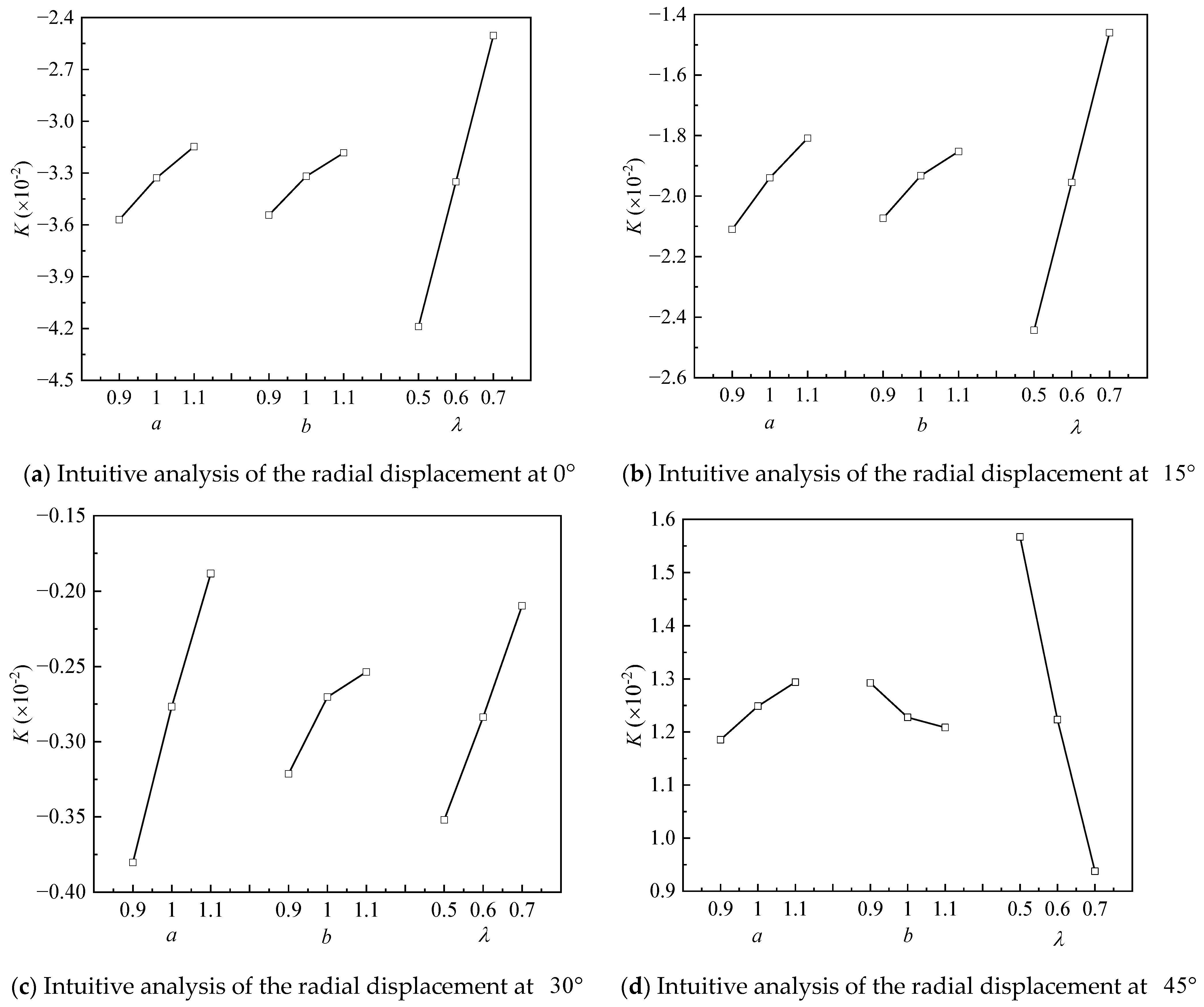
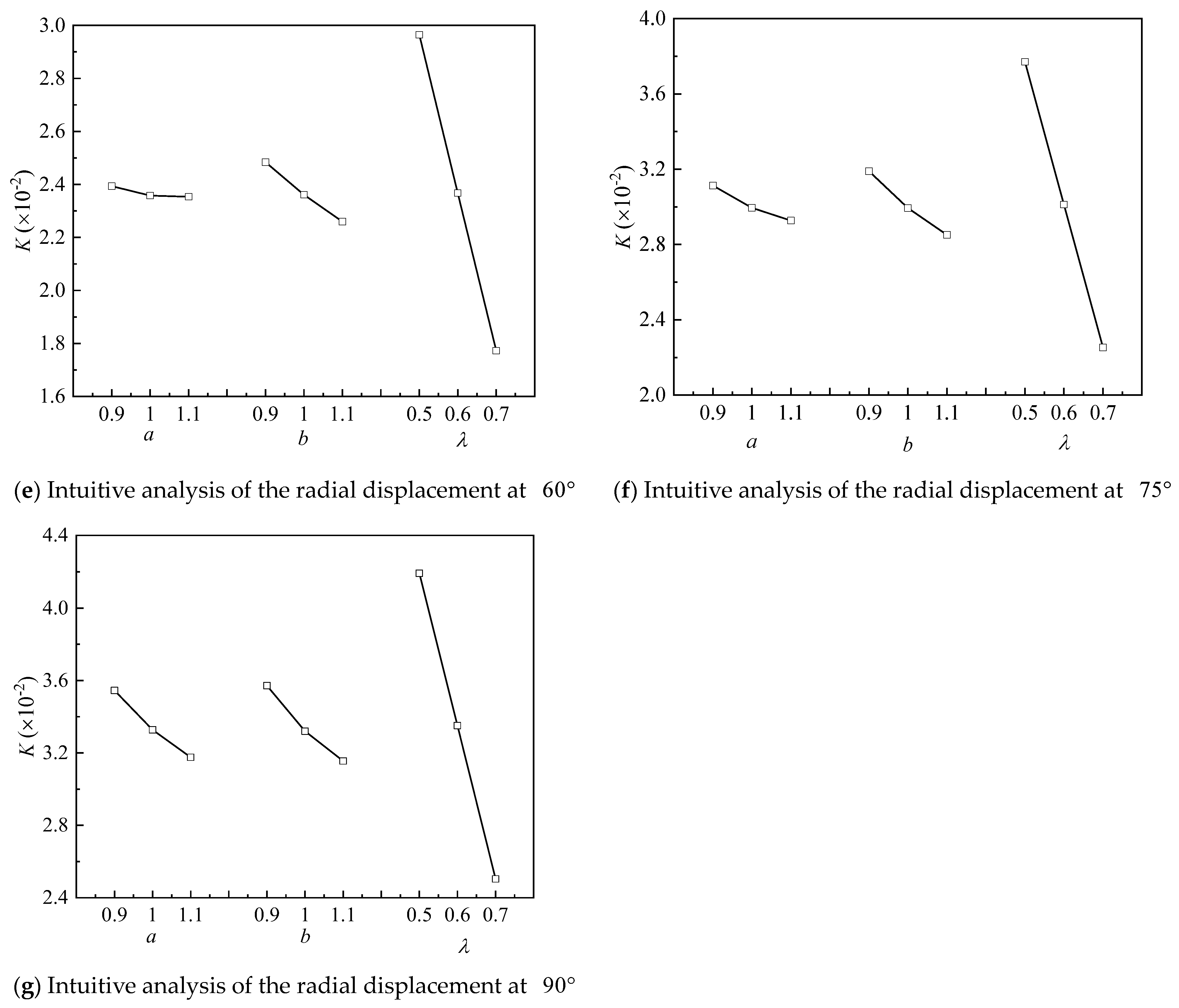
Under the condition that the other parameters remain unchanged, the influence of
a on the radial displacement and section moment in the range of
at the axis of functionally graded lining is studied. In addition, the influence of
a on the typical points of
,
,
,
,
,
and
at the axis of functionally graded lining is studied, and the results are shown in
Figure 4 and
Figure 5.
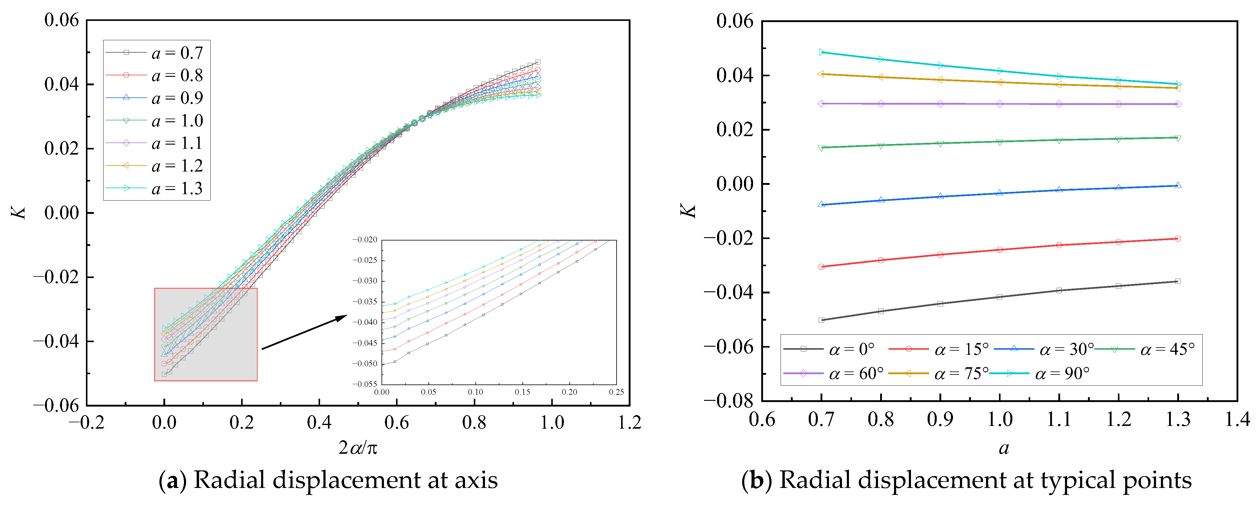
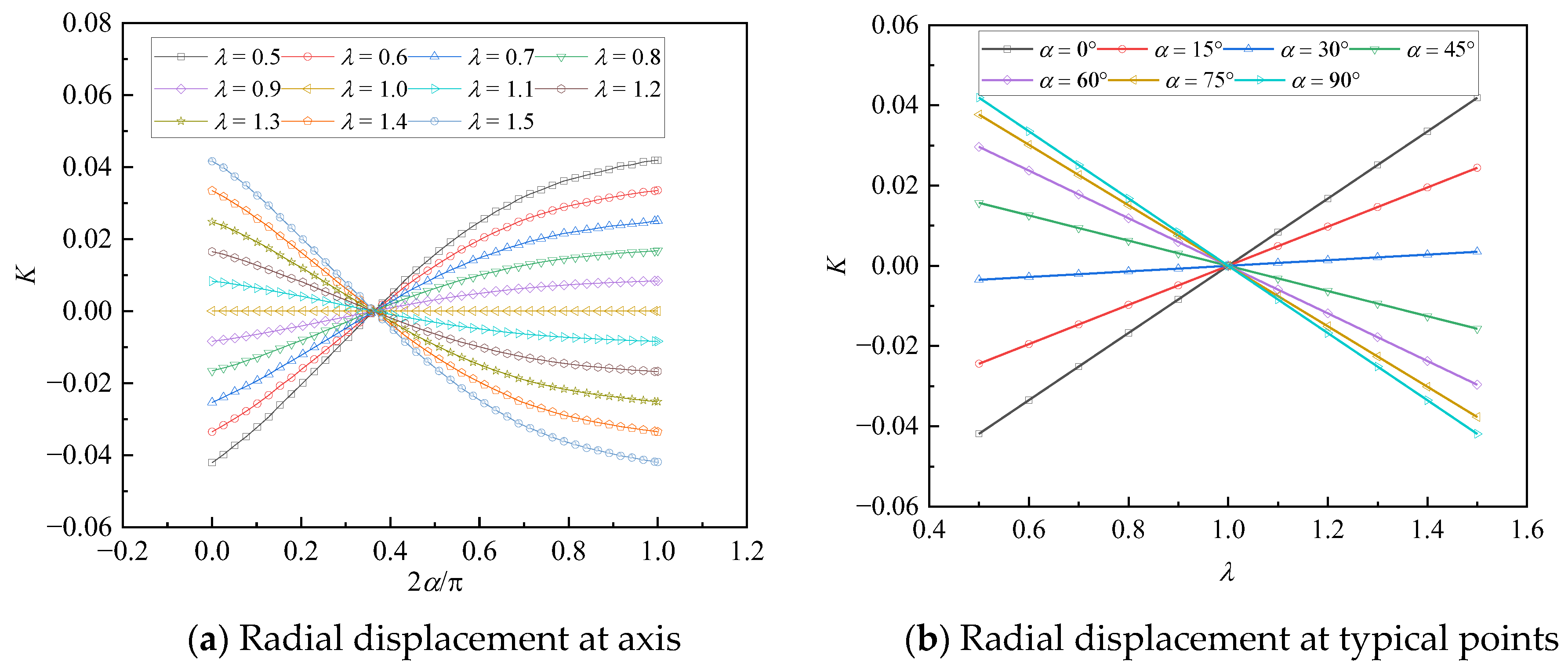
As can be observed from
Figure 4a, with the increase in
a, the radial displacement at the lining axis decreases, but the deformation trend of the lining is consistent with the maximum displacement at
and
and the minimum displacement near
. In addition, from
Figure 4b, with the increase in
a, the slope of the radial displacement curve of each typical point decreases gradually. It shows that the increase in
a can enhance the stiffness of the lining, but the reduction in deformation becomes smaller and smaller.
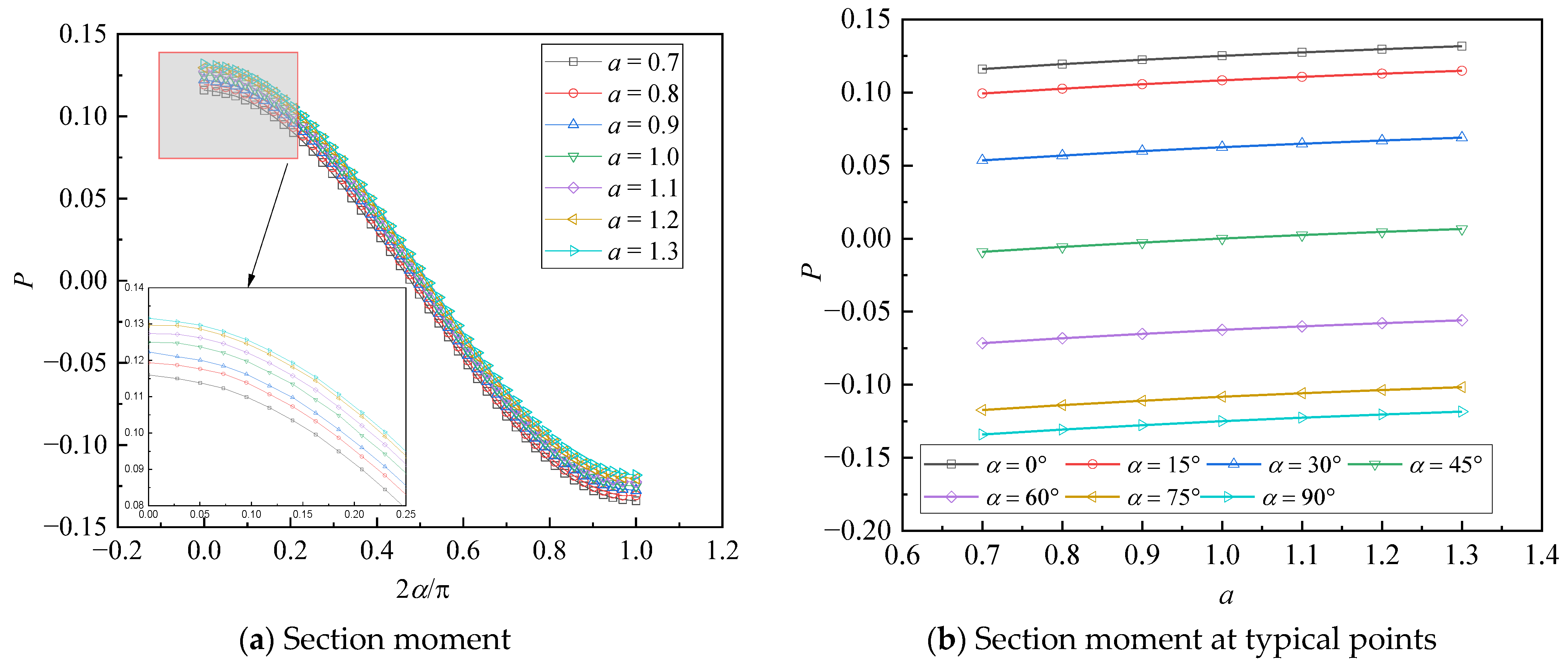
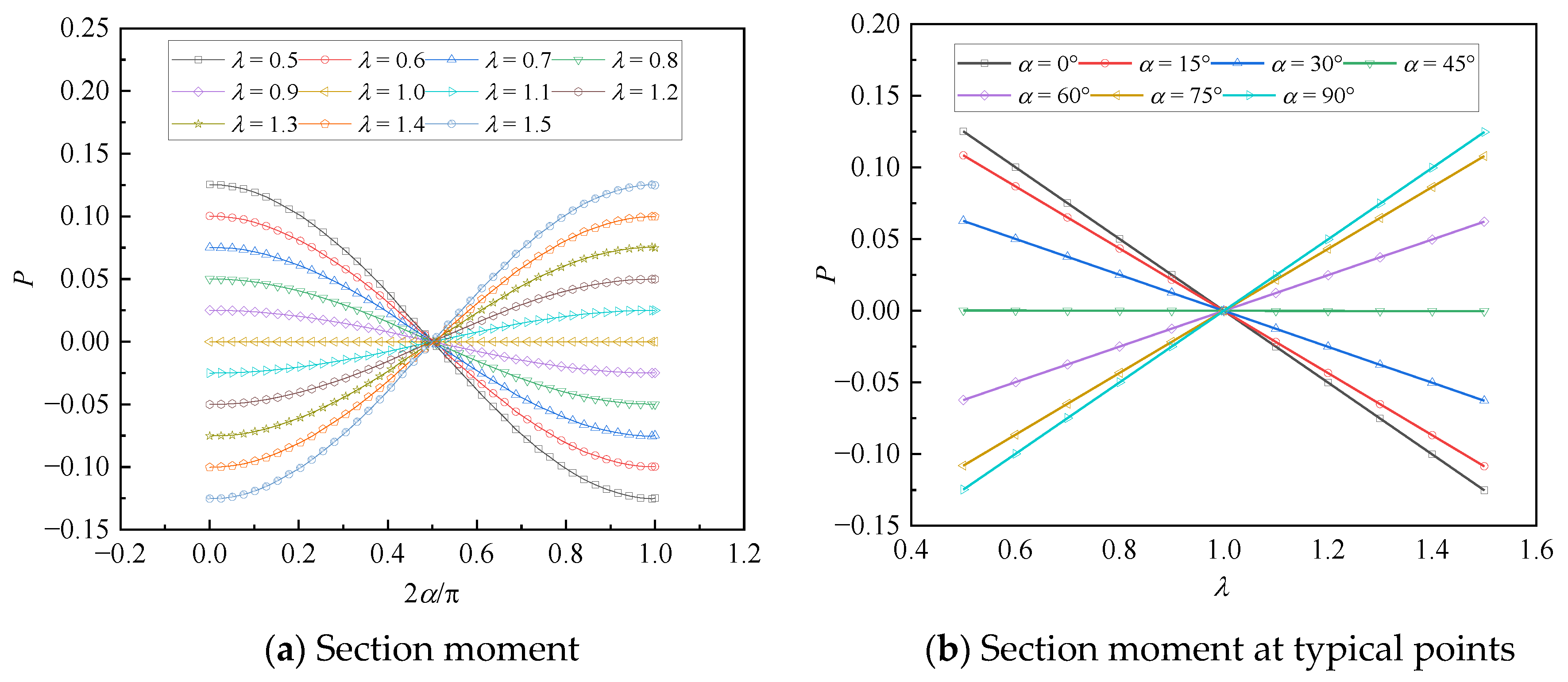
From
Figure 5a, with the increase in
a, the distribution trend of section moment is consistent with the maximum moment at
and
and the minimum moment near
. In addition, from
Figure 5b, with the increase in
a, the negative section moment at typical points decreases linearly, and the positive section moment increases linearly. The maximum section moment transfers from the section of
to the section of
, and the maximum section moment decreases.
It can be observed from the distribution of the displacement and internal force that the optimal mode of the elastic modulus is to configure the larger elastic modulus at
and
to improve the rigidity, and the smaller elastic modulus at
to achieve the full utilization of the material. The optimized elastic modulus function is given by Equation (15), which is defined as Function II.
Under the condition that the other parameters remain unchanged, the influence of
b on the radial displacement and section moment in the range of
at the axis of functionally graded lining is studied. In addition, the influence of the typical points of
,
,
,
,
,
and
on the axis of functionally graded lining is studied, and the results are shown in
Figure 6 and
Figure 7.
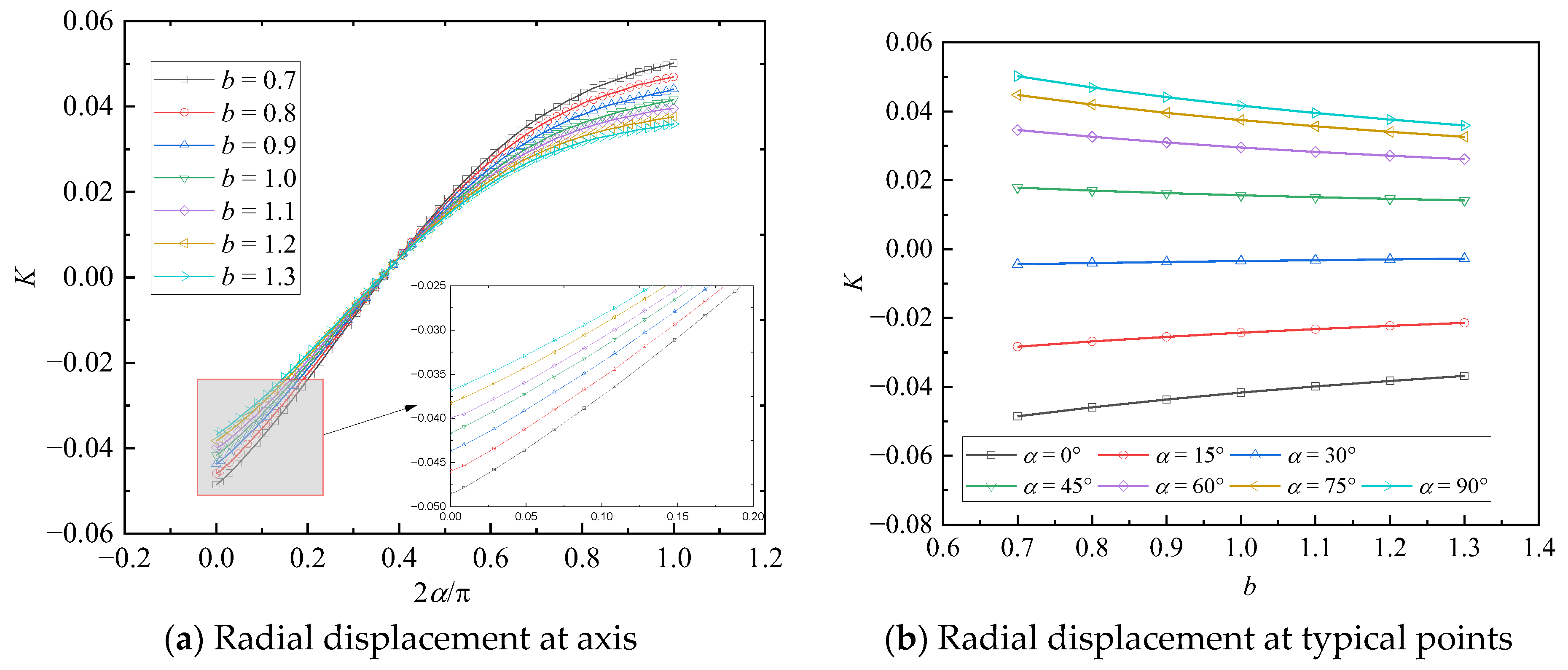
As can be observed from
Figure 6a, with the increase in
b, the radial displacement at the lining axis decreases, but the deformation trend of the lining is consistent with the maximum displacement at
and
and the minimum displacement near
. In addition, from
Figure 6b, with the increase in
b, the slope of the radial displacement curve of each typical point decreases gradually. It shows that the increase in
a can enhance the stiffness of the lining, but the reduction in deformation becomes smaller and smaller. Comparing
Figure 6 with
Figure 4, it can be found that the effect of changing
a or
b alone on the deformation characteristics of functionally gradient lining is the same when other parameters remain unchanged.
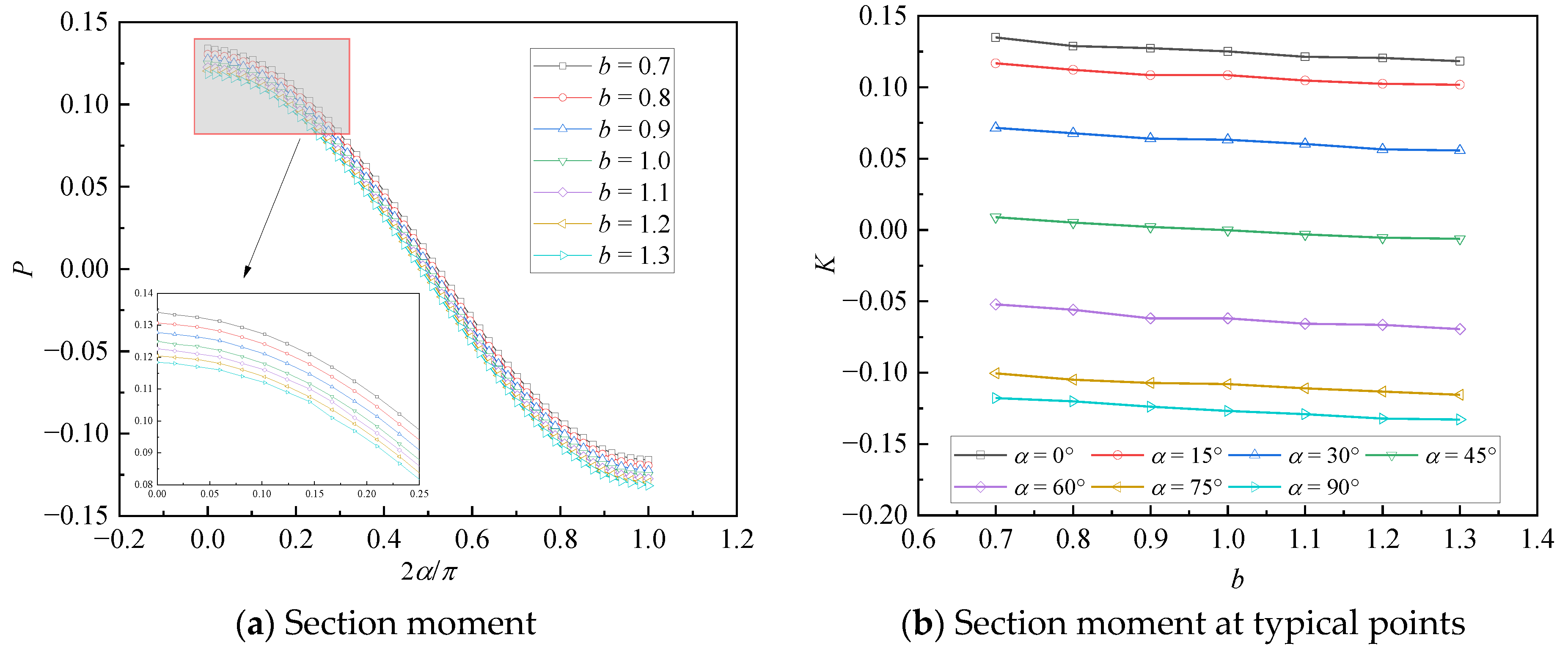
From
Figure 7a, with the increase in
b, the distribution trend of section moment is consistent with the maximum moment at
and
and the minimum moment near
. In addition, from
Figure 7b, with the increase in
b, the negative section moment at typical points increases linearly, and the positive section moment decreases linearly. The maximum section moment transfers from the section of
to the section of
, and the maximum section moment decreases. Comparing
Figure 7b with
Figure 5b, it can be found that with the increase in the section stiffness, the section moment also increases.
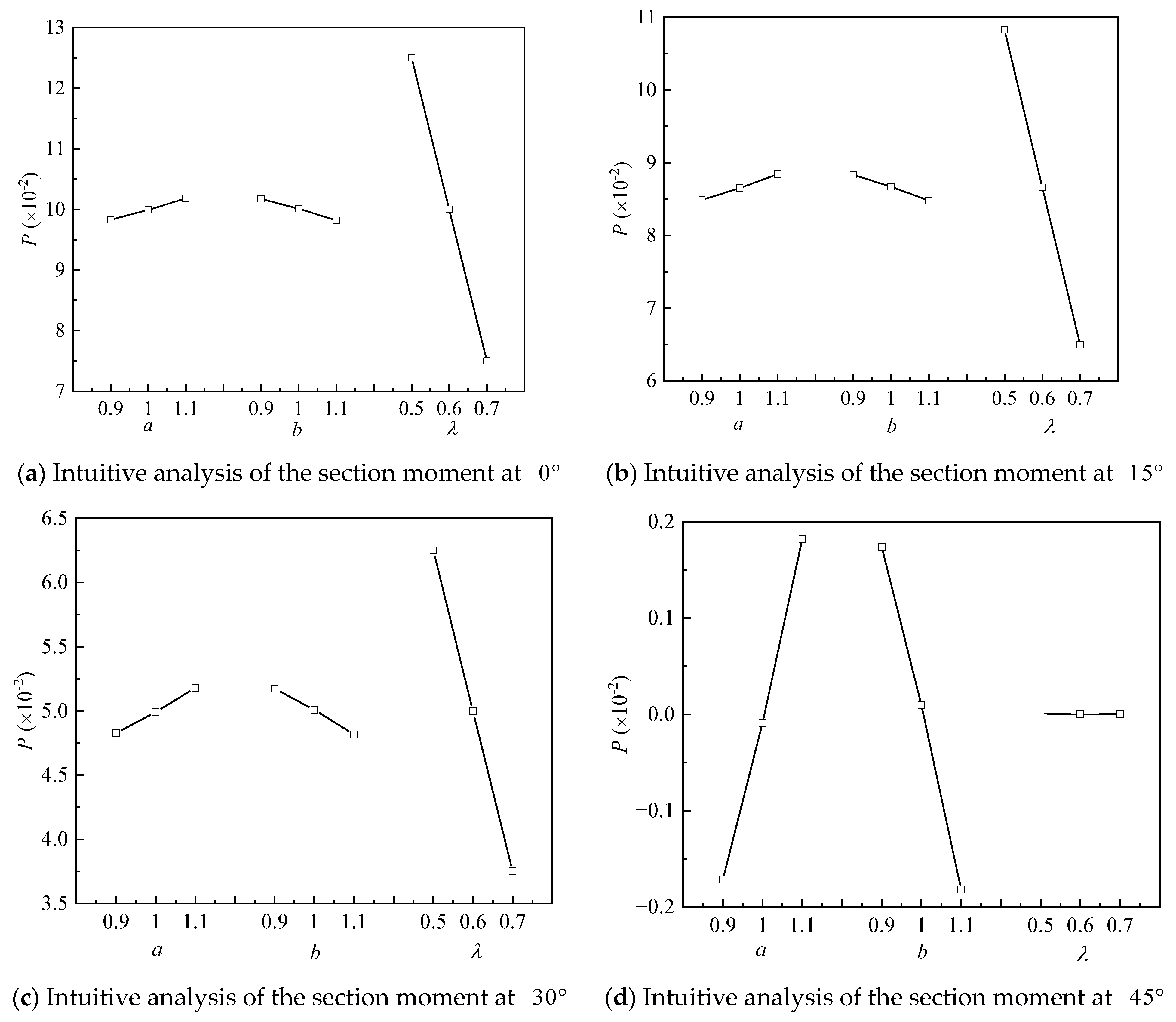
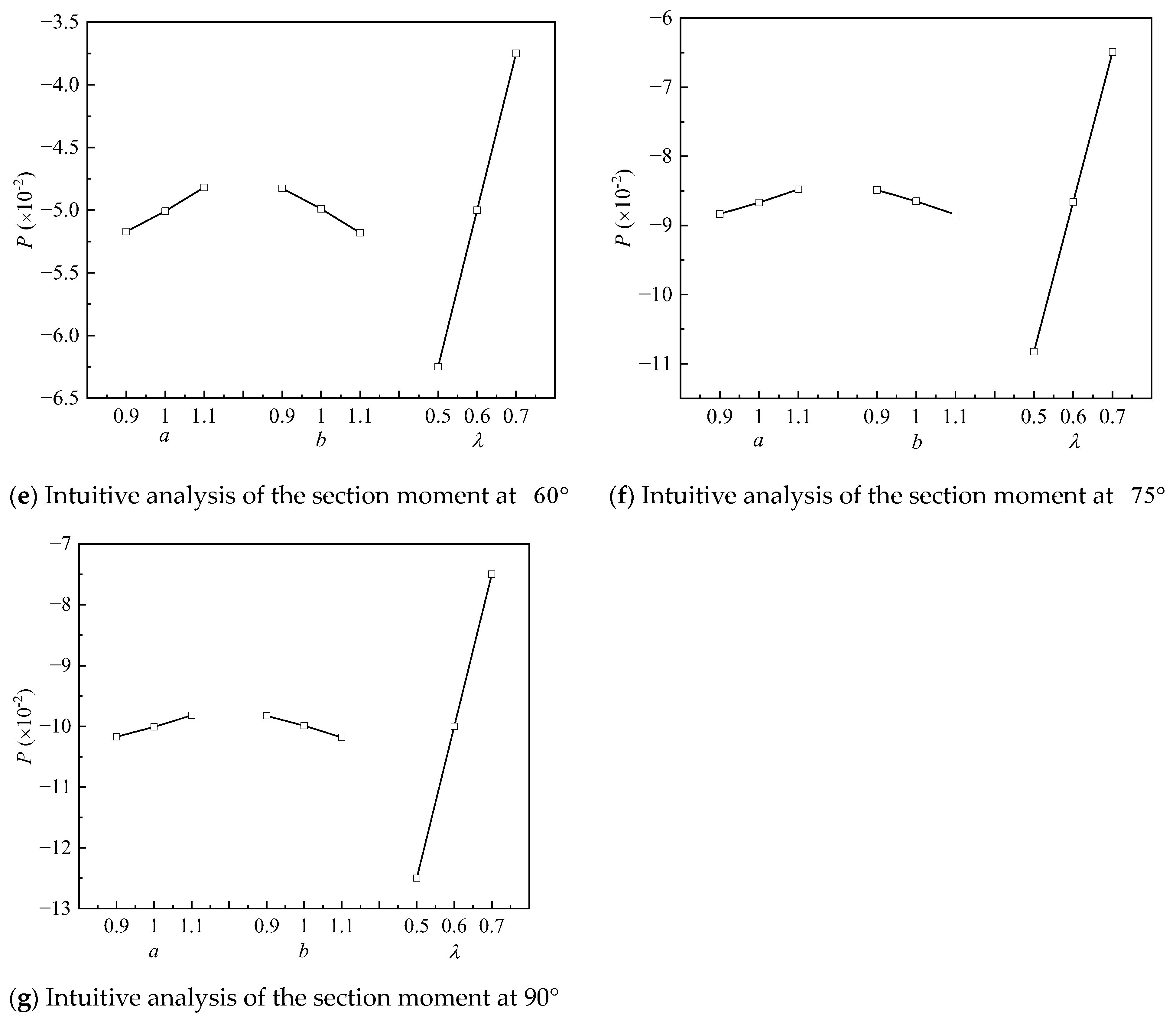
Under the condition that the other parameters remain unchanged, the influence of
on the radial displacement and section moment in the range of
on the axis of functionally graded lining is studied. In addition, the influence of the typical points of
,
,
,
,
,
and
at the axis of functionally graded lining is studied, and the results are shown in
Figure 8 and
Figure 9.
From
Figure 8a and
Figure 9a, the radial displacement of the lining axis and the section moment are 0 when
, which means that when the upper load is equal to the lateral load, the lining is in the safest state. When
, the curves of the radial displacement and the section moment are symmetric with the curve of
.
From
Figure 8b and
Figure 9b, it can be observed that the displacement of the lining axis and section moment changes linearly, and the deformation mode of the lining changes significantly with the increase in
. It turns into the deformation with large lateral pressure to the inside, and the side with small pressure to the outside, which conforms to the actual deformation characteristics.
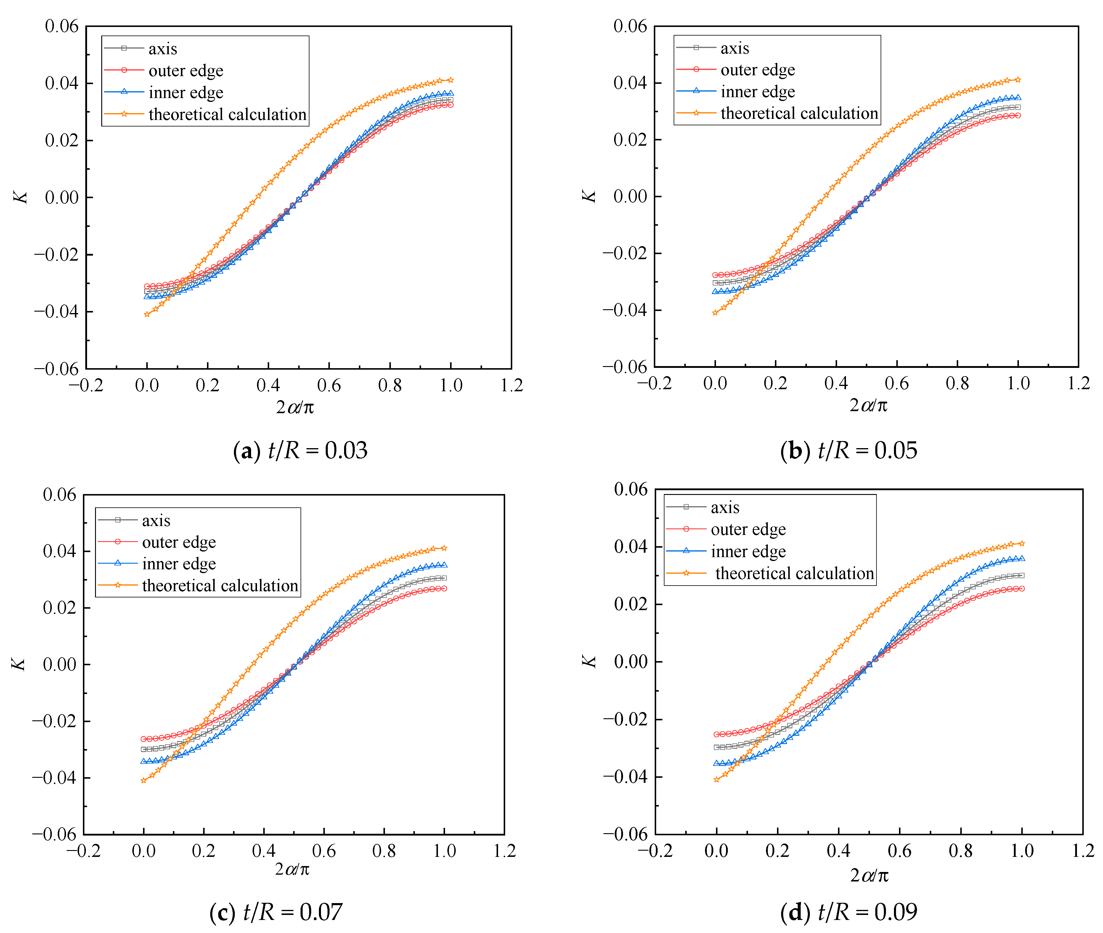
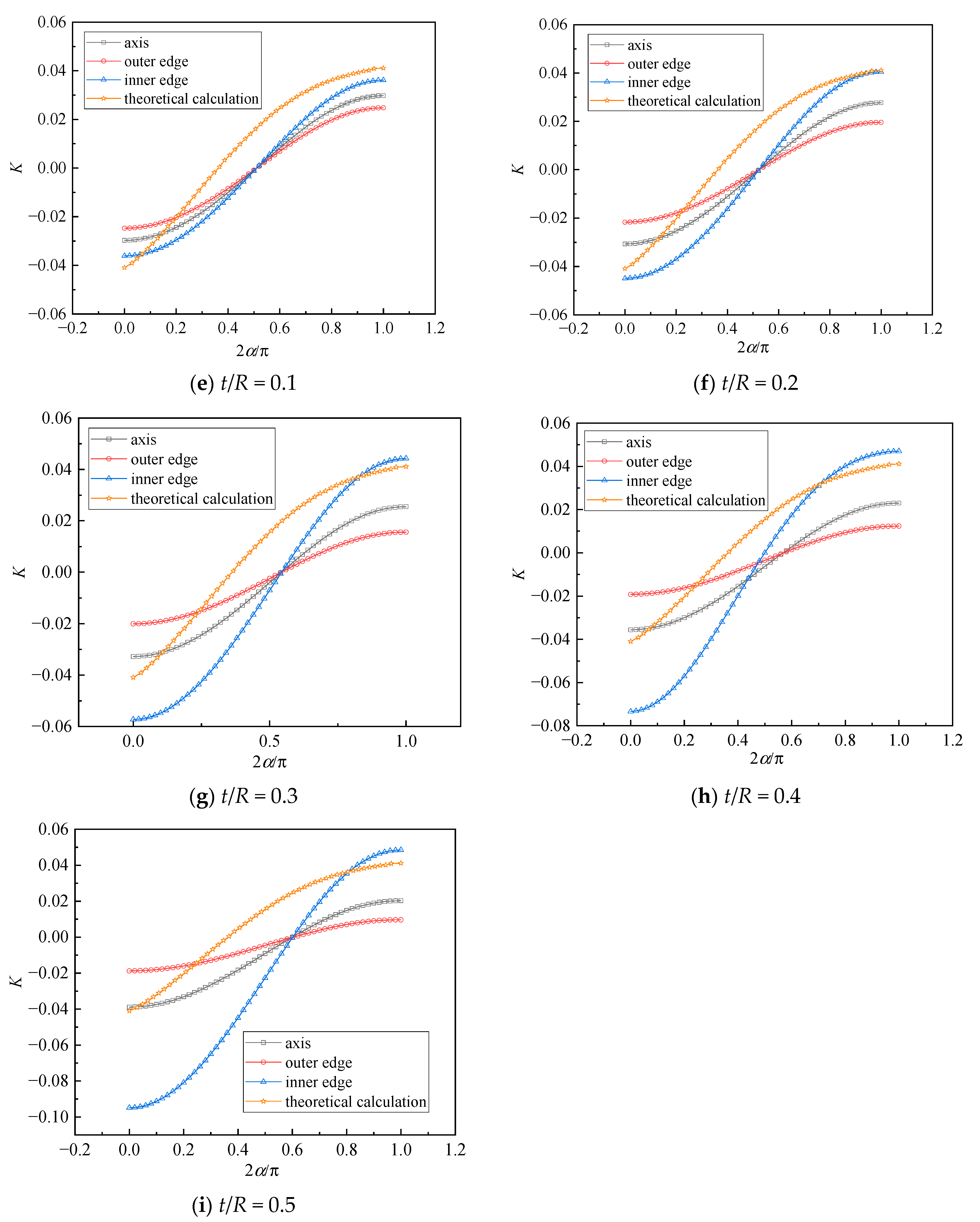
2.7. Verification of the Numerical Simulation
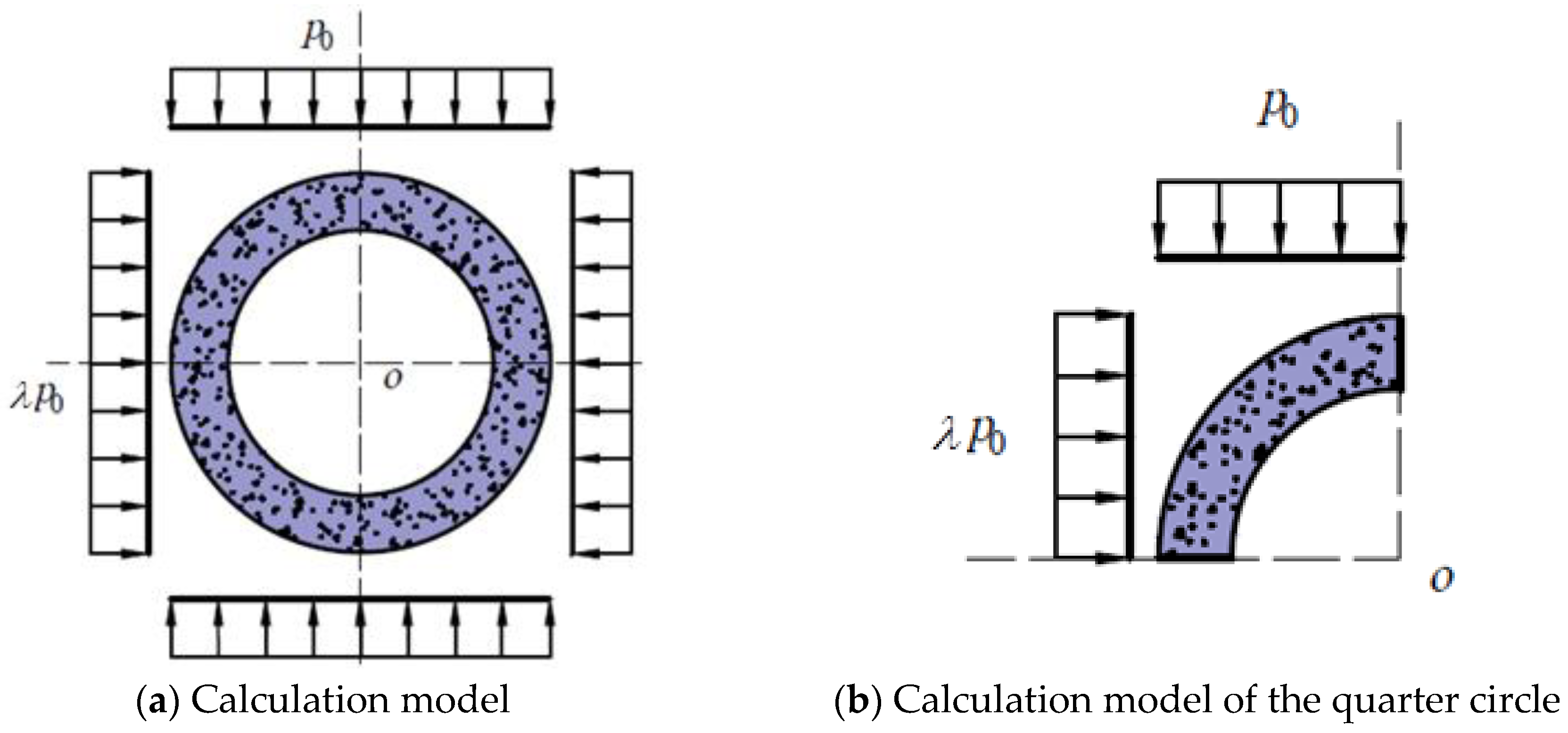
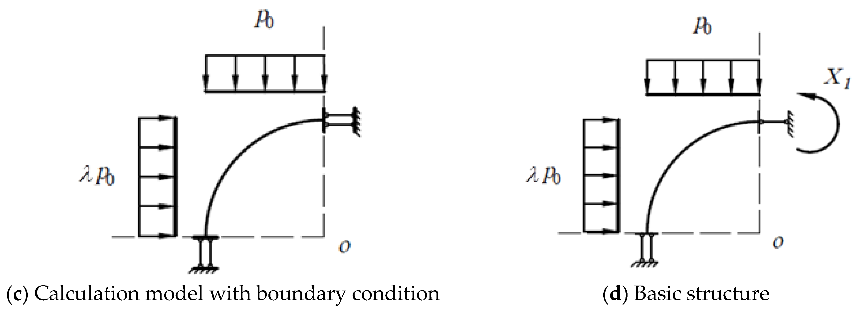
In the numerical calculation, the lining of subway tunnels has a certain thickness, but in the theoretical calculation, the lining is simplified as a curved rod structure. Therefore, under the condition of the different thickness diameter ratio, the displacement calculation results of the inner wall, outer wall and axis of the lining in the numerical calculation are compared with the theoretical calculation results, so as to determine the corresponding position of the radius
in the theoretical calculation. The calculation results are shown in
Figure 12.
From
Figure 12, it can be observed that the radial displacement at the inner edge of the cylinder is the largest, followed by the axis, and the outer edge is the smallest, indicating that the inner edge of the cylinder structure should be used as the basis for failure under the action of external force. When
, the theoretical calculation results are close to the radial displacement of the inner edge of the cylinder in the numerical simulation results. With the increase in the thickness diameter ratio, the numerical simulation results of the radial displacement of the inner edge at
and
gradually increase. When
, the numerical simulation results of the radial displacement of the inner edge at
and
are closest to the theoretical calculation results. However, when
, the numerical simulation results of the radial displacement of the inner edge at
and
exceed the theoretical calculation results, and the gap between them gradually becomes larger. It shows that when
, the theoretical calculation results can be used to calculate the radial displacement of the inner edge, and the calculation results are conservative. However, when
, if the theoretical model continues to be applied to calculate the radial displacement at the most unfavorable position, the results will be smaller, which is not conducive to the safety of the structure. In conclusion, the theoretical model of internal force and deformation is suitable for the
cylinder structure.
According to the comparison of the radial displacement between the numerical simulation and the theoretical calculation under the different thickness diameter ratios, the function gradient cylinder under the condition of is simulated. The adopted elastic modulus functions are Function I and Function II. In order to reflect the economic characteristics of the functionally graded structures (FGS), two groups of elastic modulus parameters , and , are used. The vertical load is 1 MPa, and the fundamental elastic modulus E0 = 36 GPa.
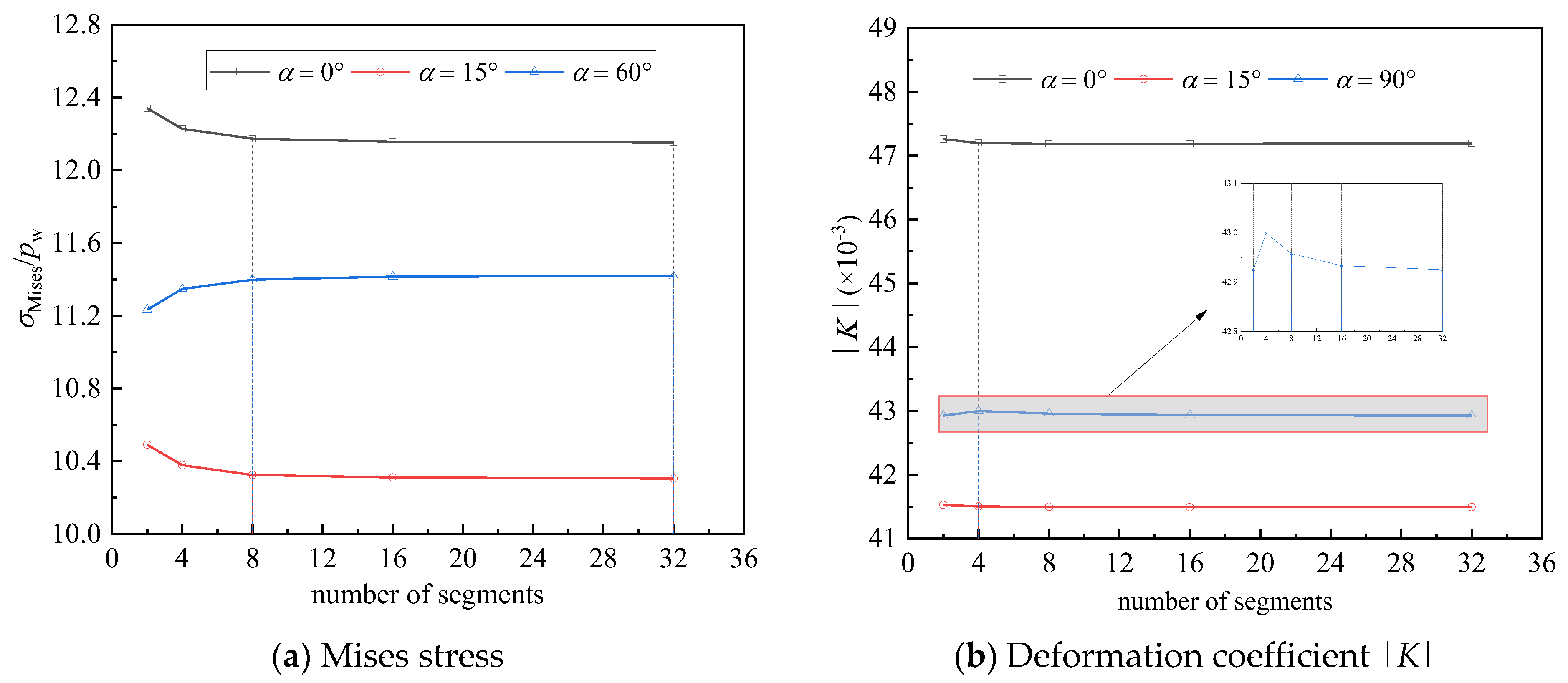
Because ABAQUS 6.14 cannot realize the continuous change in the elastic modulus along the circular direction, the cylinder structure is adopted to give the elastic modulus along the circular direction in sections. When there are enough segments, it can be considered that the cylinder with segments given the elastic modulus is equivalent to the functional gradient cylinder in mechanical properties. Next, the number of segments is explored. The change trend of Mises stress and deformation coefficient |
K| with the number of segments at typical points is shown in
Figure 13.
From
Figure 13, it can be observed that with the increase in the number of segments, the Mises stress and radial displacement coefficient |
K| at the inner edge of the cylinder gradually converge to a certain value, so when the number of segments is large enough, the method of elastic modulus given by segments can be used to simulate the functional gradient lining. It can be also observed that when the number of segments is 16, the stress and deformation begin to converge. When the number of segments is 32, the change degree of Mises stress and the radial deformation coefficient of each typical point is less than 0.05% and 0.02%, respectively. Therefore, in order to ensure the accuracy of calculation and reduce the calculation, in the next simulation of the mechanical properties of the FGM cylinder, the 1/4-cylinder structure is divided into 16 sections to simulate the FGM cylinder.
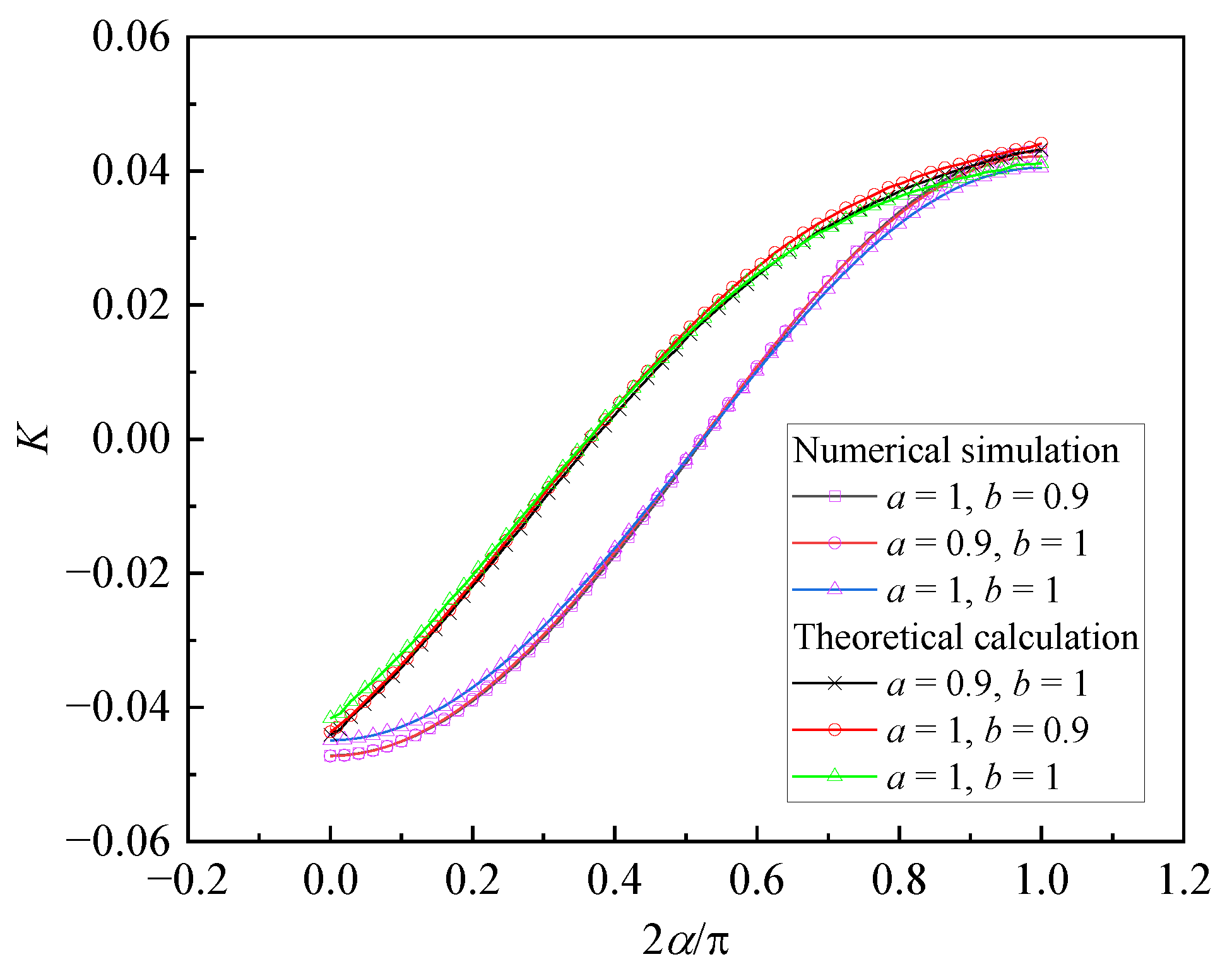
Based on the above demonstration of the thickness diameter ratio and the number of segments of the functional gradient cylinder in the numerical simulation, the mechanical properties of functional gradient linings with
and the number of segments of 16 are analyzed, and the deformation coefficient
K of the functional gradient lining under the condition of the elastic modulus Function I is compared with the theoretical calculation result, and the comparison result is shown in
Figure 14. The radial displacement of FGM lining with different elastic modulus parameters in the theoretical calculation and numerical simulation is shown in
Figure 15. Compared with the radial displacement of FGM linings with two elastic modulus functions, the result is shown in
Figure 16.
From
Figure 14, the radial displacement curves of FGM lining almost coincide under the conditions of
,
and
,
in the results of both the theoretical analysis and the numerical simulation. There is a certain gap in the results between the theoretical analysis and the numerical simulation, but the theoretical analysis and the numerical simulation results are close at the two places of
and
with large displacement, where the gap between the two calculation results is within 8%, so the theoretical calculation results can be used as the basis for the deformation of the lining.
From
Figure 15, under the condition of the linear distribution of the elastic modulus, the radial deformation of lining is slightly different with different elastic modulus parameters in both the theoretical calculation and the numerical simulation. From
Figure 15a, the maximum radial displacement is at
. The maximum radial displacement of homogeneous lining is the smallest and the functional gradient lining with elastic modulus parameter
,
is the second, and the functional gradient lining with elastic modulus parameter
,
is the largest. In addition, the difference between the maximum deformation of functionally graded lining with
,
and that of homogeneous lining is no more than 5%. From
Figure 15b, similarly, the maximum radial displacement is at
in the numerical simulation. The maximum radial displacement of homogeneous lining is the smallest and the functional gradient lining with elastic modulus parameter
,
is the second, and the functional gradient lining with elastic modulus parameter
,
is the largest. In addition, the difference between the maximum deformation of functionally graded lining with
,
and that of homogeneous lining is no more than 5%. In conclusion, although there are some differences in the results between the theoretical analysis and the numerical simulation, the laws shown by them are consistent. When
, the maximum deformation is at
, and
is conducive to reduce the maximum deformation.
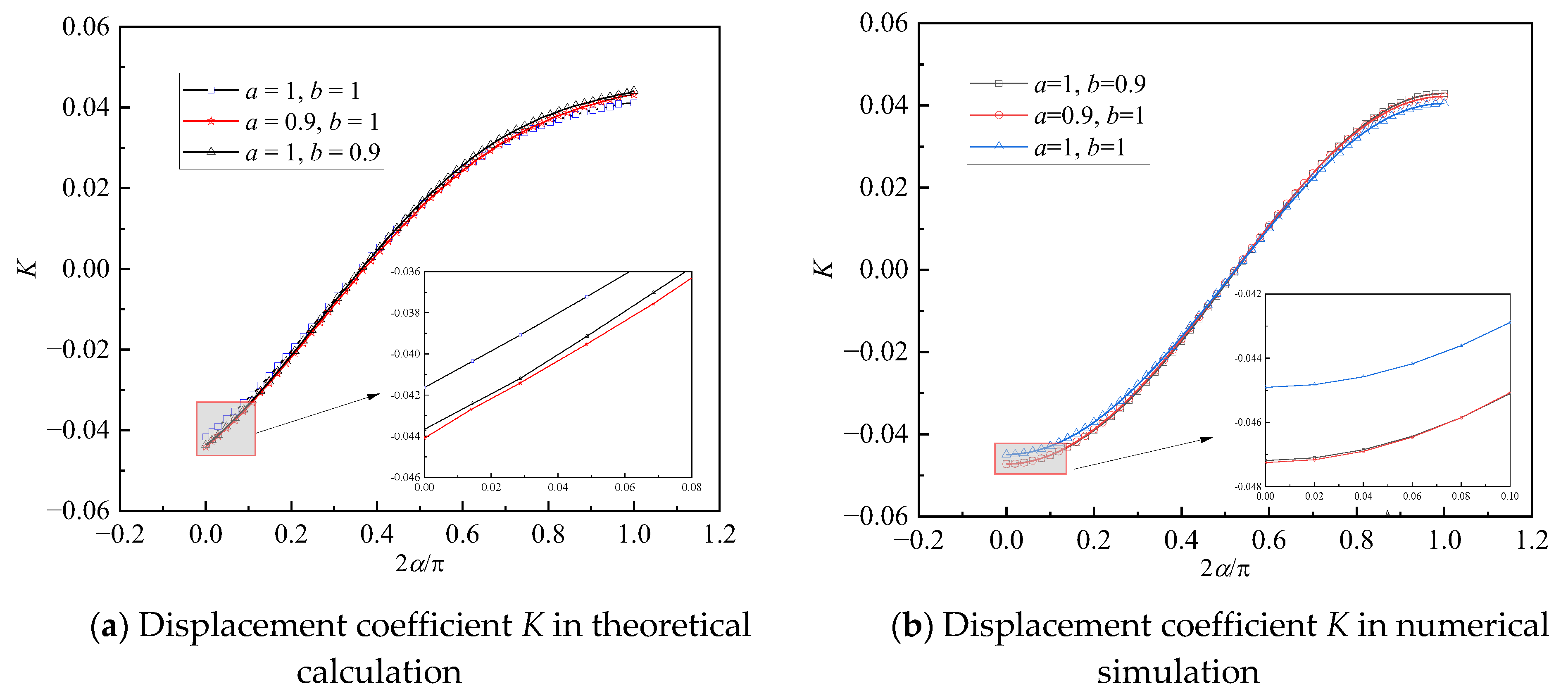
From
Figure 16, the deformation of the functionally graded lining corresponding to the two elastic modulus functions is similar, but the circumferential stress is quite different. From
Figure 16a, the circumferential stress of functional gradient lining corresponding to elastic modulus Function II is larger near
and is about 30% larger than that corresponding to Function I. From
Figure 16b, the radial displacement of the four functional gradient linings reaches the maximum value at
, and the deformation difference is about 2%. The radial displacement of the functional gradient lining corresponding to Function II with
,
is the minimum, and that of the functional gradient lining corresponding to Function I with
,
is the second. It can be observed that Function II has some advantages over Function I in reducing the maximum deformation of the structure, but the advantages are relatively low and the overall stiffness of the functional gradient structure represented by Function II is also larger. Therefore, when Function I can meet the deformation requirements, it is unnecessary to use Function II to reduce the deformation further.


 ,
, 


