Article

Resonance Suppression of a Maglev Inertially Stabilized Platform Based on an Improved Recursive Least Square Algorithm

Aerospace College of Sun Yat-Sen University, Guangzhou 510006, China
*
Author to whom correspondence should be addressed.
Appl. Sci. 2022, 12(7), 3362; https://doi.org/10.3390/app12073362
Submission received: 1 March 2022 / Revised: 22 March 2022 / Accepted: 24 March 2022 / Published: 25 March 2022

Abstract

:
Mechanical resonance occurs during the operation of a maglev inertially stabilized platform (MISP). The MISP is driven by the motor gear and the gear clearance changes during commutation, which makes the resonance frequency variable. Conventional notch filters with constant parameters are not ideal for variable frequency resonance suppression. In this study, the forgetting factor in the recursive least squares (RLS) algorithm was improved to estimate the resonance frequency online. By adjusting the frequency parameters of the notch filter, the proposed measures can effectively suppress the variable frequency resonance in a dual-stage MISP system. Finally, a simulation example is presented to validate the arguments in this study.

1. Introduction

With the increasing demand of high-accuracy pointing for LOS (line of sight), growing attention has been paid to the MISP [1,2], which places magnetic bearings in the inner gimbal of the conventional gimbal system to achieve dual-stage stabilization [3,4]. A variety of factors affect the performance of the MISP, and it is of great significance to improve the control precision of the inertial stabilization platform. Lin [5] established and the modeled the maglev dual-stage systems and applied different control strategies. In the study in [6], a new adaptive controller versus an H∞ control was proposed on a magnetic levitation. In [7,8], an extended state observer (ESO) was adopted to estimate the disturbances, and the disturbances were compensated in real time to achieve a high precision compound control. Jia [9] designed a neural network backstepping sliding mode controller to estimate the nonlinear friction between the frames and three-axis vehicle inertial stabilization platform system, which is helpful for the real-time estimation and compensation on the nonlinear friction. The MISP is driven by a motor gear, which is an elastic structure. The existence of an elastic structure leads to mechanical resonance [10]. When the resonant frequency is high enough to exceed the control bandwidth, it has little effect on the control system. When the resonant frequency is low, the performance of the control system deteriorates, owing to the mechanical resonance. In the MISP, the ratio of the stiffness between the drive shafting and the gimbal frame is low, and the equivalent stiffness changes with gear clearance. Therefore, the resonance frequency is variable [11]. It is necessary to take measures to suppress mechanical resonance.
The studies in [12,13] presented a method of employing a disturbance observer to estimate the torque brought by resonance, which could be fed back to the input and compensated. Filtering is a common method of resonance suppression. The conventional notch filter joins between the output of the speed loop and the input of the current loop and can significantly suppress the resonance at a constant frequency [14,15,16] but is unable to effectively restrain the resonance at variable frequencies.
Several studies [17,18,19] have been conducted on adaptive notch filters to realize resonance suppression. In [17], a fractional-order low-pass filter substituted the integer-order low-pass filter to achieve a better tradeoff between robustness and resonance suppression. The study in [18] proposed a novel excitation signal for a vibration test to improve the system performance and locate the resonance frequency to adjust the frequency parameter of the notch filter in time. The study in [19] proposed an adaptive infinite impulse response (IIR) filter based on the recursive least squares algorithm, managed to estimate the resonance frequency, and adjusted the filter parameter online.
The RLS algorithm is suitable for parameter identification and signal processing. Many scholars have focused on improving the recursive least squares algorithm [20,21,22,23]. In [20], a recursive extended least squares (RELS) algorithm was presented to provide an unbiased estimation of model parameters online. The performance of the RLS algorithm is governed by the forgetting factor, which influences tracking capability and misadjustment. The study in [21] used the output error to control the forgetting factor and proposed a novel modified RLS algorithm to strengthen the accuracy of sparse system identification. The studies in [22,23] put forward variable forgetting factor RLS algorithms, and they took control of the value of the forgetting factor to make the algorithm robust for both stationary and nonstationary input signals, achieving fast convergence and low misadjustment. In [24], an extended recursive least squares algorithm was proposed to identify recursively both the system parameters and the dynamic disturbance and improved the estimation accuracy of time-invariant system parameters.
Few studies have been conducted to improve the resonance-suppression ability of the MISP. The study in [4] analyzed the coupling effect of a dual-stage system on resonance suppression ability. A dual-stage stabilization platform is based on the isolation of the payload by a magnetic bearing from the gimbal system. It can provide fine pointing with a high closed-loop bandwidth, while the gimbal system follows the payload to maintain the gap of the magnetic bearing.
The main contributions of this study are as follows. First, the factors influencing the resonance of the MISP are analyzed. Second, an improved RLS algorithm based on the error power for the variable forgetting factor is proposed to estimate the resonance frequency online. Third, an adaptive filter combined with the improved RLS algorithm is designed to suppress mechanical resonance under the dual-stage stabilization system of the MISP.
The remainder of this paper is organized as follows. The MISP structure is introduced in Section 2, where the relationship between the resonance of the MISP and the gear transmission is given. In Section 3, an adaptive resonance suppression method is presented, including the improvement in the forgetting factor of the RLS algorithm and an adaptive notch filter. In Section 4, the feasibility of the proposed method for MISP variable-frequency resonance suppression is validated through simulation. Finally, Section 5 concludes the study.

2. The MISP Structure

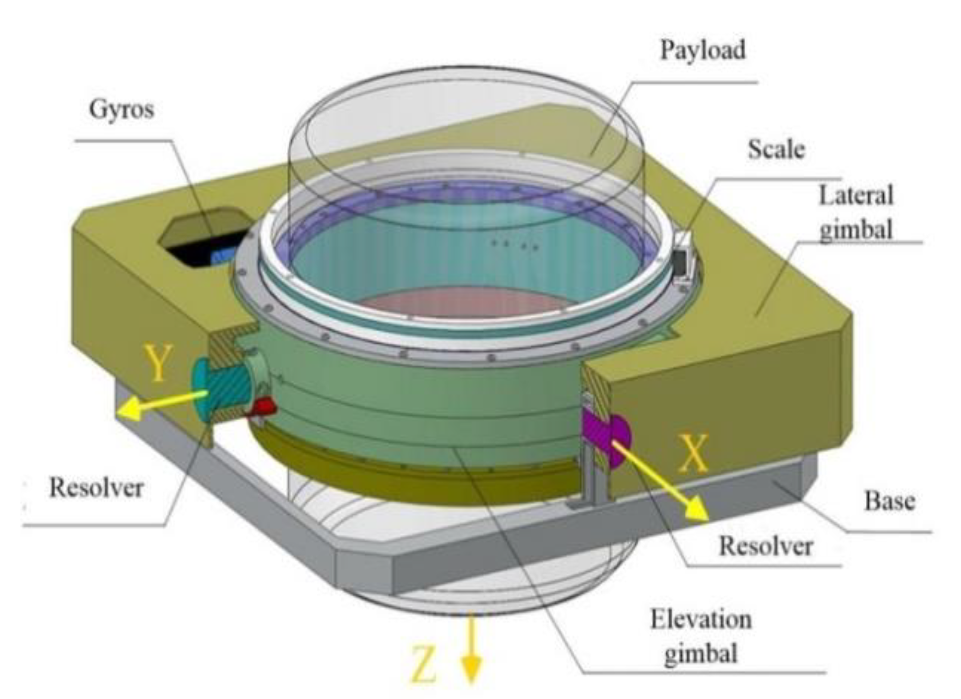
2.1. Introduction of MISP System

A structural diagram of the MISP is shown in Figure 1. The frame of the MISP is composed of a base assembly, a lateral outside gimbal, and an elevated inner gimbal. The base assembly is installed on the vehicle through four shock absorbers to help eliminate the high-frequency vibration from the vehicle. The mechanical bearing connects the lateral gimbal with the base so that the lateral gimbal rotates around the longitudinal axis of the vehicle. A magnetic bearing is placed in the elevation gimbal as a fine stage to isolate the residual angular movement of the inner gimbal, and the payload instrument is suspended by gimbals, which forms the magnetic levitation system. Motor–gear systems are used to drive the gimbles. Resolvers are mounted on the end of the axes to measure the gimbal angles, which are restricted in a sway of ±8°. Angular rate gyros are installed on the elevation gimbal in the corresponding directions to furnish angular velocity feedback for the stabilizing loops in both directions. Platform controllers are installed on the corners of the lateral gimbal.
A conceptual drawing of the MISP is depicted in Figure 2. The payload is levitated in five degrees of freedom (DOF), including the axial translation along Z, radial translation along X’ and Y’, and the slight rotation around the axial X and axial Y. F A , F B F c , and F d are the magnetic force at four locations and adjusted by controllers. The degree of freedom to tilt around the radial direction of the magnetic bearing and the other DOFS are decoupled from each other, which can be referred to in [3,7].
Thus, the elevation gimbal control and the lateral gimbal control can be generalized as a single-DOF dual-stage control system. The MISP control block diagram for the pile-up control strategy [4] is shown in Figure 3. Because the gimbal is driven by motor–gear systems, there is a resonance structure in the coarse control channels, which is represented in orange. The dual-stage stabilization model is written as follows
{ m x ¨ f = u f + k Δ x + T f M x ¨ c = u c u f k Δ x + T c
where x f and x c denote the tilting angles of the fine and coarse stages, respectively. Δ x is the relative angle and k is the tilting negative stiffness in the magnetic force. u f and u c are the corresponding control inputs and m and M are the moments of inertia. T f and T c are the disturbances acting on the fine and coarse stages, respectively, which are relatively low-frequency vibrations from the base and high-frequency nonlinear friction. C f and C c are the PID controllers in the fine and coarse stages, and take the forms
  C f = K p ( 1 + D s + I / s )
  C f = k p ( 1 + d s + i / s )
where K p , D ,   I are the proportional coefficient, differential coefficient and integral coefficient of C f , respectively. k p ,   d , and i are the proportional coefficient, differential coefficient, and integral coefficient of C c . s is the variable in frequency system function.

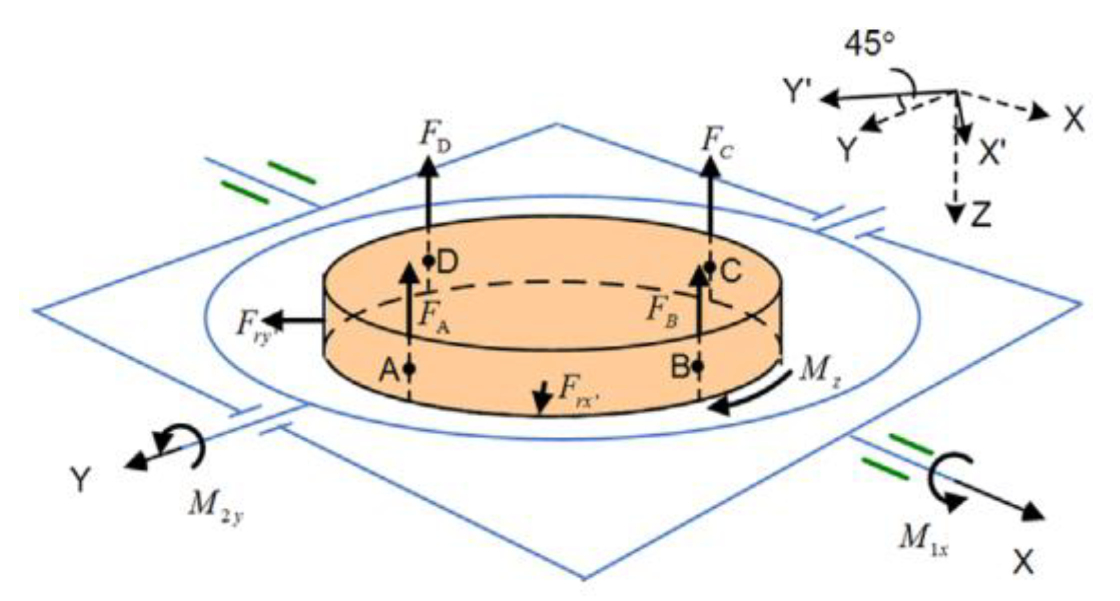
2.2. Transmission Structure

The gimbal frame of the MISP is driven by a motor, shaft coupler, gear, and racks, which are regarded as servo systems, and its structure is shown in Figure 4. It is equivalent to a double-inertia transmission system with clearance, as depicted in Figure 5.
A dynamic model of the MISP transmission structure can described in the following forms
{ m 0 x ¨ 0 = T e C m x ˙ 0 T w   M x ¨ c = T w C l x ˙ c T l  
where m 0 is the moment of inertia of the motor and M is the moment of inertia of the gimbal frame. C m ,   C l , and C w are the damping coefficients of the motor, gimbal, and drive shaft, respectively. Accordingly, x 0 and x c represent the angles of the motor and gimbal, respectively, and T e , T l , and T w are the torques of the motor, gimbal, and drive-shaft, respectively, where K denotes the stiffness of the transmission shaft.
The backlash model is used to describe the effect of gear clearance after approximate linearization, and the shaft moment Tw is given by
T w = { K ( x 0 x c b ) + C w ( x ˙ 0 x ˙ c ) , x 0 x c > b 0 , b x 0 x c b K ( x 0 x c + b ) + C w ( x ˙ 0 x ˙ c ) , x 0 x c < b  
where b is related to gear model.
The relationship between the amplitude of the angle error and the clearance is used as the description function N(A) of the backlash model [11], taking the form
N ( A ) = 1 2 π ( arcsin ( b A ) + b A 1 ( b A ) 2 ) , b < A
where A is the amplitude of the angular error. The range of N(A) is 0–1. With approximate linearization of N(A) in a certain range, the elastic coefficient of the model with clearance can be equivalent to the product of K and N(A) without clearance, expressed by
  K = K × N ( A )
K * can be regarded as the equivalent elastic coefficient of a model with clearance. When C m and C l are too small to be neglected, the transfer function from the motor output torque T e to its angular velocity x ˙ 0 is deduced as
  G m ( s ) = 1 ( m 0 + M ) s M s 2 + C w s + K m p s 2 + C w s + K = 1 ( m 0 + M ) s G m ( s )
where m p is equivalent inertia, stated as
    m p = m 0 M m 0 + M
G m is the link leading to mechanical resonance, denoted as
  G m ( s ) = M s 2 + C w s + K m p s 2 + C w s + K = ( s ω z ) + 2 ξ z ω z s + 1 ( s ω p ) + 2 ξ p ω p s + 1
where ω p and ω z are the resonant and antiresonant frequencies, respectively. ξ z and ξ p represent resonant damping and antiresonant damping, respectively. They are expressed by
{ ω p = K * m p , ω z = K * M     ξ p = C w 2 m p K * , ξ z = C w 2 M K *
Under the assumption that C w is 0, the transfer function from motor torque T e to angular error Δ x between the motor and gimbal can be deduced as
  G Δ x ( s ) = 1 m 0 m p m p s 2 + K
The step response of Δ x in time domain can be obtained as
    Δ x ( t ) = T e m 0 ( ω p ) 2 ( 1 cos ( ω p t ) )
Hence, the amplitude is given by
  A = 2 T e m 0 ( ω p ) 2
From the Equations (7), (11), and (14), it can be seen that the existence of the clearance reduces the stiffness coefficient of the system, and the decrease in the stiffness coefficient causes the resonance frequency to diminish and the amplitude to increase, which means that the negative effect of the resonance is intensified. Therefore, it is necessary to take measures to suppress the resonance.

3. The MISP Structure

3.1. Proposed Improvement on RLS Algorithm

Parameter identification is a theory in which the unknown parameters of the system are identified through an algorithm combined with input and output data. The RLS algorithm is one of the methods of parameter identification, and is given by
  y = ( x 1 x n ) ( θ 1 θ n )
where y is the output data and ( x 1 x n ) is the input data.   n is the length of unknown parameters. ( θ 1 θ n ) T is a system parameter to be identified. The matrices of the input data, output data, and system parameters were recorded as
  Y k = [ y 1 y k ] T
  Φ k = [ ϕ 1 T ϕ k T ] T
Θ = [ θ 1 θ n ] T
ϕ i T = ( x 1 i x n i )
where k is the length of observation data. The matrix form can be expressed as
  Y k = Φ k Θ
The solution of the parameter in the RLS algorithm with the forgetting factor in [18] can be expressed as
  Θ k = Θ k 1 + K k e k
where   K k is the Kalman gain vector and e k is the estimation error, which is given by
  e k = y k ϕ k T Θ k 1
When   i = 1 k λ k i e k 2 gets the minimum, Θ k obtain the optimal solution where λ is the forgetting factor.
  K k can be obtained by
  K k = P k - 1 ϕ k λ + ϕ k T P k - 1 ϕ k
where P k is the inverse of the input correlation matrix, obtained by
  P k = P k 1 P k 1 ϕ k ϕ k T P k 1 λ + ϕ k T P k ϕ k
λ ranges from 0 to 1 and affects the tracking speed and stability of the estimated parameters. When the forgetting factor is close to 1, the estimation parameters become stable and the misadjustment is lower; however, the tracking ability deteriorates. On the contrary, when the forgetting factor decreases, the tracking speed becomes faster, but this will increase the imbalance.
To balance the relationship between the convergence rate and the tracking stability for the estimation parameters, a specific function between λ and   e k is constructed to adjust the value of λ according to   e k . σ e is the power of the a priori error signal computed with a short exponential window [17] and takes the form
  σ e 2 ( k ) = α σ e 2 ( k 1 ) + ( 1 α ) e k 2
where α is the weighting factor, given by
  α = 1 - 1 / ( K α n )
with   K α 2 . Considering the noise, the power of noise   σ v 2 can be estimated with a longer exponential window taking the form
  σ v 2 ( k ) = β σ v 2 ( k 1 ) + ( 1 β ) e k 2
where β is the weighting factor, given by
  β = 1 - 1 / ( K β n )
where K β K α . Theoretically, σ e σ v and an RLS algorithm with σ e σ v will result in λ 1 . The forgetting factor of the proposed RLS algorithm is designed in the following forms
λ ( k ) = 1 1 + μ | σ e 2 ( k ) σ v 2 ( k ) |
where μ is a positive constant parameter. In (25), | σ e 2 ( k ) σ v 2 ( k ) | is regarded as the effective error energy on the condition that the noise and input signal are uncorrected, and it dominates the value of the forgetting factor. It is possible that σ e is less than σ v . A limit is set to σ v [17] when
σ e γ σ v
where 1 < γ 2 .
Based on Equations (29) and (30), the variable forgetting factor is designed as
λ ( k ) = { 1 1 + μ | σ e 2 ( k ) σ v 2 ( k ) | , σ e > γ σ v λ max , σ e γ σ v

3.2. Adaptive Notch Filter

The traditional IIR notch filter with a constant frequency is designed as
H ( z ) = 1 + a z 1 + z 2 1 + a ρ z 1 + ρ 2 z 2
where α and ρ are the frequency and bandwidth parameters, respectively. The relationship between a and notch filter frequency is given by
ω n = 1 T s cos 1 ( α 2 )
where T s is the sampling time.
Because the conventional filter cannot adjust the frequency parameter online, an adaptive frequency notch filter is proposed here, and its structure diagram is shown in Figure 6.
ω(k) is the tilting speed error of the motor and gimbal frame; yω(k) is the output after passing through the notch filter; d(k) is the expected output, which is generally zero. The improved RLS algorithm proposed in the previous section was used to estimate the resonant frequency, and then the frequency-related parameter in the notch filter was updated.
The gradient of yω(k) with respect to a is deduced as:
φ ( k ) = [ Δ ω ( k ) ρ y ω ( k ) ] z 1 1 + a ρ z 1 + ρ 2 z 2
Combined with the improved RLS algorithm, the complete adaptive iterative filtering algorithm can be summarized as follows:
  • Step 1: initialize a ( 0 ) = a 0 , P ( k ) = δ I , σ ε 2 ( 0 ) = 0 ;
  • Step 2: update e ( k ) = d ( k ) y ω ( k ) ;
  • Step 3: update σ e 2 ( k ) = α σ e 2 ( k 1 ) + ( 1 α ) e 2 ( k ) , σ v 2 ( k ) = β σ v 2 ( k 1 ) + ( 1 β ) e 2 ( k ) ;
  • Step 4: update λ ( k ) according to Equation (31);
  • Step 5: update K ( k ) = P ( k 1 ) φ ( k ) λ ( k ) + φ ( k ) P ( k 1 ) φ ( k ) and P ( k ) = [ ( 1 K ( k ) ) φ ( k ) ] P ( k 1 ) ;
  • Step 6: update a ^ ( k ) = a ^ ( k 1 ) + K ( k ) e ( k ) .
δ is a small constant in Step 1, and a 0 is converted from the parameter ω p of the initial structure resonant frequency using Equation (33).

4. Simulation and Analysis

To validate the feasibility of the proposed method for resonance suppression of the MISP, a numerical simulation is presented. The relative parameters are listed in Table 1.
To simulate the actual operation of the MISP, the experimental conditions were set as follows:
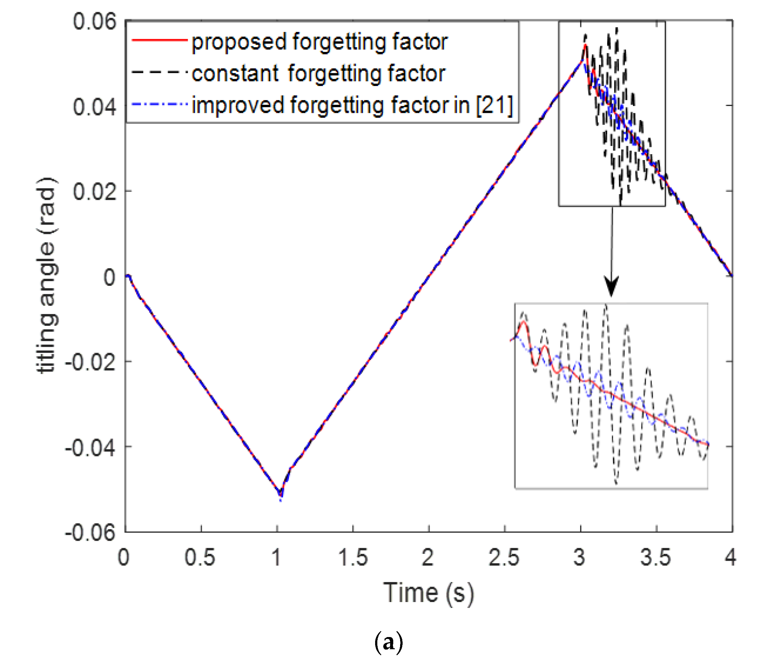
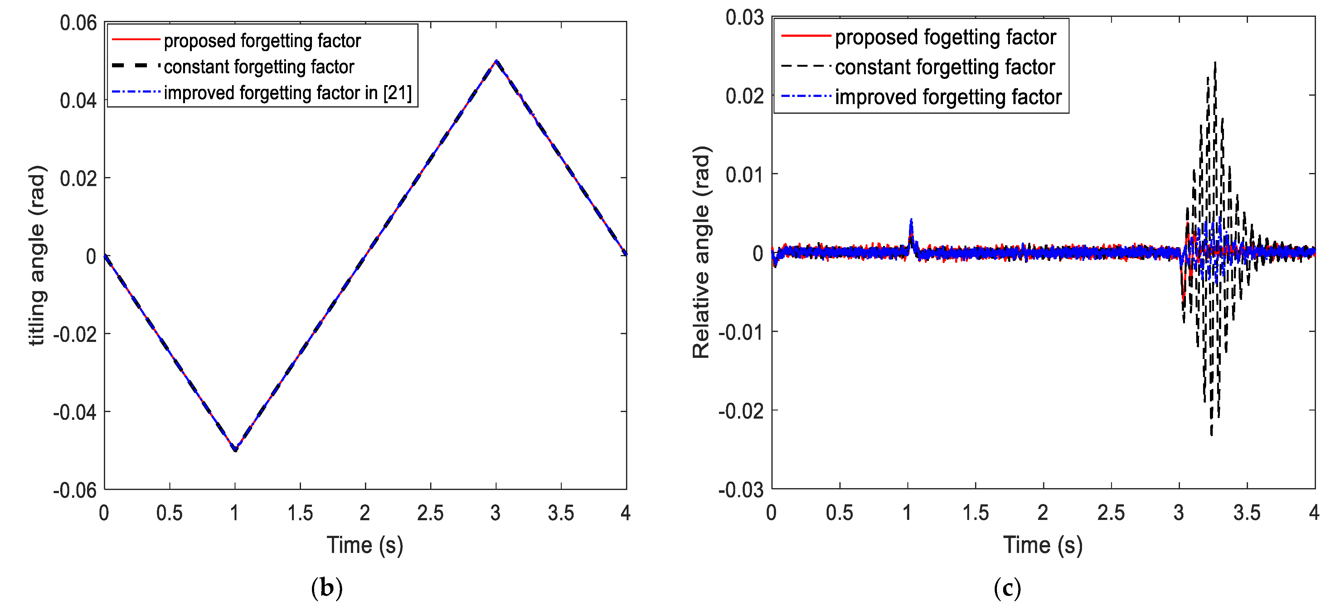
  • Input 0.05 rad/s tilting signal to the frame, and the swing period lasted for 4 s.
  • The tilting direction was changed at 1 and 3 s. It is assumed that clearance occurs in the gear rack during the direction turn around, and the transmission structure stiffness changes when N(A) is assumed to be 0.8 s and 0.5 s, respectively, which will result in a resonance frequency variable. Theoretically, the initial resonance frequency of the gimbal frame is 216 rad, which was changed to 193 rad and 164 rad.
  • The RLS algorithm with a constant forgetting factor and an algorithm in [21] were used for comparison with the improved algorithm in the simulation. The constant forgetting factor is 0.99, and the forgetting factor in [21] is given as
    λ ( k ) = b c + | e ( k ) e ( k 1 ) |
    where the value of b, c is set according to the error e ( k ) . The simulation results are shown in Figure 7 and Figure 8.
As shown in Figure 7a,b, the adaptive notch filter can effectively suppress the resonance with variable frequency in the gimbal frame with the dual-stage system so that the stabilized platform can maintain a high pointing accuracy. From Figure 7a,c, the RLS algorithm with the proposed forgetting factor is better than that with a constant forgetting factor and that in [21] for resonance suppression, especially when the resonance frequency becomes lower, and the resonance amplitude intensifies. The improvement in the resonance suppression ability of the gimbal frame can reduce the relative tilting angle between the gimbal frame and the platform and avoid exceeding the saturated gap. As shown in Figure 8., the proposed forgetting factor RLS algorithm has a better tracking ability and stability, which results in better resonance suppression for the adaptive notch filter. From Figure 7a and Figure 8, compared with that at 1 s, the resonance at 3 s is more severe, and the adjustment time is longer. This means that the resonance intensifies with a decrease in the resonance frequency when the gear gap reduces the structural stiffness, which is consistent with the conclusion in Section 2.

5. Conclusions

In this study, we analyze the transmission structure of the MISP and study the relationship between the transmission structure and the change in the resonance frequency. Gear clearance in the transmission process causes the resonance frequency of the gimbal frame to be lower than the natural resonance frequency, which worsens the resonance amplitude.
Then, an adaptive notch filter based on the improved forgetting factor RLS algorithm is proposed to suppress the resonance with variable frequency in the MISP operation. Compared with the constant forgetting factor, the improved adaptive forgetting factor based on error power reached a compromise between the fast convergence and low misadjustment in the parameter estimation. The proposed adaptive notch filter adjusts the frequency parameters according to the resonance-frequency estimation to achieve resonance suppression with a variable frequency.
Through simulation, the proposed method is proven to estimate the resonance frequency accurately online when the transmission structure changes, and to achieve a better resonance suppression effect compared with the constant forgetting factor. The reduction of the resonance amplitude is helpful in maintaining the relative position between the frame and the platform stable in the dual-stage system.

Author Contributions

Methodology, W.S.; software, W.S.; validation, W.S; formal analysis, W.S and K.L; data curation, W.S.; writing—original draft preparation, W.S.; writing—review and editing, K.L and J.W.; supervision, K.L. and J.W.; project administration, K.L. and J.W.; funding acquisition, K.L. All authors have read and agreed to the published version of the manuscript.

Funding

This research was funded by the Shenzhen Science and Technology Program (grant no. JCYJ20200109142205924, 202001093000459).

Institutional Review Board Statement

Not applicable.

Informed Consent Statement

Not applicable.

Data Availability Statement

The data used to support the findings of this study are included within the article.

Conflicts of Interest

The authors declare no conflict of interest.

References

  1. Ren, Z.; Stephens, L.S. Closed-loop performance of a six degree-of-freedom precision magnetic actuator. IEEE/ASME Trans. Mechatron. 2005, 10, 666–674. [Google Scholar] [CrossRef]
  2. Fang, J.; Wang, C.; Wen, T. Design and Optimization of a Radial Hybrid Magnetic Bearing with Separate Poles for Magnetically Suspended Inertially Stabilized Platform. IEEE Trans. Magn. 2014, 50, 1–11. [Google Scholar] [CrossRef]
  3. Trumper, D.L.; Olson, S.M.; Subrahmanyan, P.K. Linearizing control of magnetic suspension systems. IEEE Trans. Control. Syst. Technol. 1997, 5, 427–438. [Google Scholar] [CrossRef]
  4. Lin, Z.; Liu, K.; Zhang, W. Inertially Stabilized Platform for Airborne Remote Sensing Using Magnetic Bearings. IEEE/ASME Trans. Mechatron. 2016, 21, 288–301. [Google Scholar]
  5. Lin, Z.; Liu, K.; Zhang, L.; Zeng, D. Coupling effect and control strategies of the maglev dual-stage inertially stabilized system based on frequency-domain analysis. ISA Trans. 2016, 64, 98–112. [Google Scholar] [CrossRef] [PubMed]
  6. Javadi, A.; Pezeshki, S. A New Model-Free Adaptive Controller Versus Non-Linear H∞ Controller for Levitation of an Electromagnetic System. Trans. Inst. Meas. Control 2013, 35, 321–329. [Google Scholar] [CrossRef]
  7. Shi, W.; Liu, K.; Zhao, W. Active Vibration Isolation of a Maglev Inertially Stabilized Platform Based on an Improved Linear Extended State Observer. IEEE Access 2021, 9, 743–751. [Google Scholar] [CrossRef]
  8. Zhou, X.; Shi, Y.; Li, L.; Yu, R.; Zhao, L. A High Precision Compound Control Scheme Based on Non-singular Terminal Sliding Mode and Extended State Observer for an Aerial Inertially Stabilized Platform. Int. J. Control Autom. Syst. 2020, 18, 1498–1509. [Google Scholar] [CrossRef]
  9. Jia, T.; Li, X.-Z.; Zhang, X.-Y. Neural network sliding mode control for vehicle inertially stabilized platform. Control. Theory Appl. 2020, 38, 13–22. [Google Scholar] [CrossRef]
  10. Shin, H.; Choi, J.; Cho, H.; Hong, K. Effects of Mechanical Resonance on Vibrations of Mechanical Systems with Permanent Magnet Machines. IEEE Trans. Magn. 2014, 50, 1–4. [Google Scholar] [CrossRef]
  11. Yang, M.; Hao, L.; Xu, D. Fast identification of resonance characteristic for 2-mass system with elastic load. In Proceedings of the 2014 International Power Electronics Conference (IPEC-Hiroshima 2014–ECCE ASIA), Hiroshima, Japan, 18–21 May 2014; pp. 3174–3178. [Google Scholar] [CrossRef]
  12. Wu, B.; Lu, S.; Ning, B.; Zhou, F.; Tang, X. Mechanical Resonance Suppression of Servo System Based on ADRC and MAFC. In Proceedings of the 2020 Chinese Control and Decision Conference (CCDC), Hefei, China, 22–24 August 2020; pp. 2447–2452. [Google Scholar] [CrossRef]
  13. Yang, M.; Zheng, W.; Yang, K.; Xu, D. Suppression of mechanical resonance using torque disturbance observer for two-inertia system with backlash. In Proceedings of the 2015 9th International Conference on Power Electronics and ECCE Asia (ICPE-ECCE Asia), Seoul, Korea, 1–5 June 2015; pp. 1860–1866. [Google Scholar] [CrossRef]
  14. Harnefors, L. Implementation of Resonant Controllers and Filters in Fixed-Point Arithmetic. IEEE Trans. Ind. Electron. 2009, 56, 1273–1281. [Google Scholar] [CrossRef]
  15. Kumagai, S.; Ohishi, K.; Miyazaki, T. High performance robot motion control based on zero phase error notch filter and D-PD control. In Proceedings of the 2009 IEEE International Conference on Mechatronics, Malaga, Spain, 14–17 April 2009; pp. 1–6. [Google Scholar] [CrossRef]
  16. Chen, Y.-S.; Lin, P.-Y.; Lin, Y.-D. A novel PLI suppression method in ECG by notch filtering with a modulation-based detection and frequency estimation scheme. Biomed. Signal Process. Control 2020, 62, 102150. [Google Scholar] [CrossRef]
  17. Yang, M.; Fu, Y.; Lv, X.; Xu, D. Mechanical resonance suppression in servo system based on the fractional order low-pass filter. In Proceedings of the 2015 9th International Conference on Power Electronics and ECCE Asia (ICPE-ECCE Asia), Seoul, Korea, 1–5 June 2015; pp. 594–599. [Google Scholar] [CrossRef]
  18. Wang, M.; Liu, X.; Dong, X.; Xiong, G.; Shen, Z.; Bai, R. A Novel Method to Detect and Suppress Mechanical Resonance for Servo System. In Proceedings of the 2016 9th International Symposium on Computational Intelligence and Design (ISCID), Hangzhou, China, 10–11 December 2016; pp. 349–354. [Google Scholar] [CrossRef]
  19. Li, N.; Li, S. Suppression of servo system mechanical resonance based on adaptive IIR notch filter. In Proceedings of the 27th Chinese Control and Decision Conference (2015 CCDC), Qingdao, China, 23–25 May 2015; pp. 3418–3423. [Google Scholar] [CrossRef]
  20. Paleologu, C.; Benesty, J.; Ciochina, S. A Robust Variable Forgetting Factor Recursive Least-Squares Algorithm for System Identification. IEEE Signal Processing Lett. 2008, 15, 597–600. [Google Scholar] [CrossRef]
  21. Wang, Y.; Li, C.; Tian, C. Modified recursive least squares algorithm for sparse system identification. In Proceedings of the 2015 7th International Conference on Modelling, Identification and Control (ICMIC), Sousse, Tunisia, 18–20 December 2015; pp. 1–5. [Google Scholar] [CrossRef]
  22. Benesty, J.; Rey, H.; Vega, L.R.; Tressens, S. A Nonparametric VSS NLMS Algorithm. IEEE Signal Proces. Lett. 2006, 13, 581–584. [Google Scholar] [CrossRef]
  23. Albu, F. Improved variable forgetting factor recursive least square algorithm. In Proceedings of the 2012 12th International Conference on Control Automation Robotics & Vision (ICARCV), Guangzhou, China, 5–7 December 2012; pp. 1789–1793. [Google Scholar] [CrossRef]
  24. Dong, S.; Yu, L.; Zhang, W.-A.; Chen, B. Robust extended recursive least squares identification algorithm for Hammerstein systems with dynamic disturbances. Digit. Signal Process. 2020, 101, 102716. [Google Scholar] [CrossRef]
Figure 1. The MISP structure.
Applsci 12 03362 g001
Figure 2. Conceptual drawing of MISP system.
Applsci 12 03362 g002
Figure 3. The MISP control diagram with pile-up control strategy.
Applsci 12 03362 g003
Figure 4. The transmission structure of gimbal frame.
Applsci 12 03362 g004
Figure 5. The transmission diagram.
Applsci 12 03362 g005
Figure 6. The adaptive notch filter structure diagram.
Applsci 12 03362 g006
Figure 7. Titling angles of the MISP under adaptive resonance suppression: (a) The titling angle of the gimbal frame. (b) The titling angle of the stabilized platform. (c) The relative tilting angle of dualstage systems.
Applsci 12 03362 g007aApplsci 12 03362 g007b
Figure 8. Resonance frequency estimation.
Applsci 12 03362 g008
Table 1. System parameters in simulation.
ParameterSymbolValueUnit
Equivalent inertia of motor and reducerm00.0432kg/m2
Inertia of gimbal frameM3.2kg/m2
Inertia of platformm1.6kg/m2
Negative
stiffness
k50,000Nm/rad
Parameter about forgetting factorsα0.5_
Weighting factorsβ0.67_
Stiffness of transmission shaftK2000_
Damping of transmission shaftCw1_
IIR filter
bandwidth parameter
ρ0.9_
Time stepTs0.001s
Coarse system
controller
kp5833_
i2_
d0.03_
Fine system
controller
Kp300,000_
I100_
D0.003_
Publisher’s Note: MDPI stays neutral with regard to jurisdictional claims in published maps and institutional affiliations.

