Article

Preliminary Investigation of Possible Biochar Use as Carbon Source in Polyacrylonitrile Electrospun Fiber Production

1
Bio-Energy Efficiency Laboratory, Engineering Department “Enzo Ferrari”, University of Modena and Reggio Emilia, Via Vivarelli 10/1, 41125 Modena, Italy
2
Institut für Anorganische Chemie, Leibniz Universität Hannover, Callinstr. 7, 30167 Hannover, Germany
3
Laboratorium für Nano und Quantenengineering (LNQE), Leibniz Universität Hannover, Schneiderberg 39, 30167 Hannover, Germany
4
Faculty II, Hochschule Hannover, University of Applied Sciences and Arts, Ricklinger Stadtweg 120, 30459 Hannover, Germany
5
INTERMECH Inter-Departmental Center, University of Modena and Reggio Emilia, Via Vivarelli 2, 41125 Modena, Italy
*
Author to whom correspondence should be addressed.
Appl. Sci. 2022, 12(9), 4441; https://doi.org/10.3390/app12094441
Submission received: 26 February 2022 / Revised: 21 April 2022 / Accepted: 26 April 2022 / Published: 27 April 2022
(This article belongs to the Special Issue Biochar: Preparation and Surface Adsorption Applications)

Abstract

:
Electrospinning with consequent thermal treatment consists in a carbon fiber production method that spins a polymer solution to create fibers with diameters around a few hundred nanometers. The thermal treatments are used for the cyclization and then carbonization of the material at 1700 °C for one hour. The unique structure of micro- and nano-carbon fibers makes them a promising material for various applications ranging from future battery designs to filtration. This work investigated the possibility of using milled gasification biochar, derived from a 20 kW fixed-bed gasifier fueled with vine pruning pellets, as an addictive in the preparation of electrospinning solutions. This study outlined that solvent cleaning and the consequent wet-milling and 32 µm sifting are fundamental passages for biochar preparation. Four different polyacrylonitrile-biochar shares were tested ranging from pure polymer to 50–50% solutions. The resulting fibers were analyzed via scanning electron microscopy, and energy-dispersive X-ray and infrared spectroscopy. Results from the morphological analysis showed that biochar grains dispersed themselves well among the fiber mat in all the proposed shares. All the tested solutions, once carbonized, exceeded 97%wt. of carbon content. At higher carbonization temperatures, the inorganic compounds naturally showing in biochar such as potassium and calcium disappeared, resulting in an almost carbon-pure fiber matrix with biochar grains in between.

1. Introduction

Market and research are in the constant pursuit of new technologies and treatments to improve the properties of mechanical components. Human society has been increasing the magnitude of global production constantly for several decades. Environmental problems such as waste management, and the need to reduce CO2 and other pollutants and to produce energy in a sustainable way, are creating pressures on the research to find new sustainable materials and technologies. Biochar could play a major role in this process. The biochar consists in the carbonized biological material obtained through thermochemical conversion processes such as pyrolysis and gasification [1]. Nowadays, biochar has well-documented applications, such as geopolymers additivation [2], insulation materials production [3], water remediation [4,5], and soil amendment [6,7]. Biomass-derived char is also gaining interest in high-tech carbon-based materials, i.e., using biochar as a graphene precursor [8,9] or blending graphene and biochar to produce new materials [10].
Within this literature framework, the presented work aims to investigate the possibility of including biochar as a carbon source in electrospun PolyAcryloNitrile (PAN)-based carbon nanofibers. The literature review shows a few attempts to use carbon sources derived from biomass thermochemical conversion in electrospun fiber production: Moulefera et al. [11], in their literature review, investigated the preparation of carbon nanofibers from biomass and biopolymers as precursors using electrospinning as the manufacturing method; Velez et al. in 2018 used additivated and non-additivated pyrolysis bio-oil in a melt-spinning process [12]; Nan et al. in 2017 and Li et al. in 2021 both included char from hydrothermal liquefaction in PAN-spun fibers [13,14].
Gasification-derived biochar has still not been investigated in the literature, opening the question of the feasibility of the proposed aim. Pyrolysis and hydrothermal gasification are widely used for char production due to the large biochar yield values (up to 30%wt) that can be obtained from these processes [1]. On the other hand, pyrolysis and hydrothermal carbonization are endothermic processes that require an external source of heat to operate [1]. Gasification systems produce less char compared to pyrolysis (about 2–10%wt.), but they have the major advantage that biochar is the byproduct of a renewable bioenergy (thermal and/or electric) production process [1]. A second advantage relies on the specific biochar production conditions in gasification reactors: gasifiers are characterized by higher temperatures (600–1100 °C) compared to pyrolysis reactors (300–600 °C). These conditions create a more regular physical structure of the gasification biochar that moves toward the graphene one, as it is described in [15]. Therefore, this study aims to investigate whether gasification-derived char can be included as a carbon source in carbon fiber production.
Carbon NanoFibers (CNFs) are fibers less than 1 μm in thickness. These fibers are a new class of superior engineered materials due to their excellent mechanical and electrical properties. CNFs reach 600 GPa in Young’s modulus [16,17]. CNFs and carbon fibers are usually fabricated through various spinning methods. After spinning, the fibers undergo the heat treatment, which allows the carbonization of the material. This thermal process is divided into two: stabilization and carbonization [18,19]. The spinning system uses a solution composed of a polymer and a solvent. The concentration ratio of the solution is usually in the range of 10–30% of polymer/70–90% solvent, depending on the applications [18,20]. Further to the mechanical properties, CNFs are particularly interesting due to the range of possible applications, among which filtration plays a major role. The process takes advantage of the small diameters and a high surface area/volume ratio. Different branches of engineering employ nonwoven ultrafine fiber mats: biomedical and industrial fields such as membrane technology, filtration media, energy harvesting, electrical power transmission and storage, tissue engineering, medical prostheses, drug delivery, and wound healing [5,20,21].
In this work, the constituting polymer chosen for the spinning dope solution was PAN. It is a synthetic colorless polymer with the linear formula (C3H3N)n, obtained from the polymerization of acrylonitrile. It has a thermoplastic behavior and does not melt under usual operation conditions for the above-mentioned applications, as it has a high crystalline melting point at 317 °C and a glass transition temperature at 104 °C [22,23]. The yearly worldwide amount of PAN produced is around 2.73 million tons [24]. PAN fibers are also the most used precursor in the production of high-quality carbon fibers, covering around 90% of the market [23]. The carbon content in PAN is 67.9%; therefore, it has, compared to other precursors, a high yield of carbonized fibers above 50%, combined with a high Young’s modulus and good mechanical properties [25]. It is fundamental that the polymer precursor has an acrylonitrile content above the 85%, not being an homopolymer, otherwise the final product will not result in a satisfactory PAN precursor fiber [25].
In this work, different shares of biochar derived from biomass gasification were added to the spinning material. The aim of the experimental part was to define if biochar particles can be included in the fiber material despite differences in the diameter. Biochar, compared to PAN, is produced in an inexpensive way; indeed, it is an energy production byproduct. By reducing the amount of PAN in carbon fibers production, the cost of production and the use of nonrenewable resources could be reduced. The biochar share in the material will also contribute to the shift in the carbon footprint toward a partial carbon negativity. To further stress the importance of by-product-derived biochar, this work used the char produced through vineyard pruning gasification [26]. Unfortunately, by-products such as vine pruning material are usually characterized by higher inorganic contents compared to high-quality biomass fuels (i.e., wood pellets) [27]. For this reason, particular attention was paid to the role and the presence of inorganics through all the fiber production processes. Biochar must be properly cleaned and milled before using it in the solution. Despite the milling process, biochar particles strongly differed in size from the fibers, suggesting that more performing milling procedures should be used in the future. On the other hand, this study proved that the biochar ashes are removed during the fiber carbonization process.

2. Materials and Methods

2.1. Biochar Production

The biochar used in this work was produced in a small-scale fixed-bed downdraft gasifier (model PP30) from the US-based company “All Power Labs” [28]. The PP30 produces both electricity and biochar. The specific fuel consumption and biochar production are 1 kg/kWh and 0.1 kg biochar/kg of dry biomass, respectively. The machine has two different collection points for the char. The larger char particles are extracted underneath the reactor hearth while fine particles are collected from a thermally insulated cyclone. This work used only the char collected from the reactor. Here, the temperature during steady-state conditions exceeded 600 °C, reducing the chance to have polluting compounds in the sampled material such as Polycyclic Aromatic Hydrocarbons (PAHs) [1]. The ultimate analysis of the vine pruning pellets was derived from [26]. The carbon, hydrogen, and nitrogen shares were 46.4%wt., 6.5%wt., and 0.9%wt., respectively. The ash content was 3.6%wt. and the remaining mass consisted of oxygen bonded to the other elements. Oxygen cannot be directly detected by the ultimate analysis [1]. The calculated heating value was 19.3 MJ/kg using the Channiwala–Parikh equation [26]. Lastly, the average residence time for this specific fixed-bed reactor was derived from [29], where the gasifier consumption, its geometrical values, and the average density of the char resulted in an average residence of about 4 h under temperature conditions that ranged from 950 °C (combustion zone) and 600 °C (end of the reduction zone).

2.2. Biochar Preparation

To evaluate the size distribution, a sample of as-received biochar was processed in a vibratory sieve shaker (Retsch AS200 control G) equipped with a sieves tower composed by the following sieves: 710 µm, 500 µm, 125 µm, 63 µm, and 32 µm. An amount of 101 g of “as-received” biochar was put on top of the sieve tower, shook for 5 min, and then the process stopped and the result collected.
In a second test, to obtain a cleaner powder, biochar pellets were submerged overnight in isopropyl alcohol. IsoPropyl Alcohol (IPA) is commonly used in gasification applications to dissolve the polycyclic hydrocarbon contaminants that are carried with the gas due to incomplete gasification [30,31,32]. Previous studies [1] have shown that the gasification process consumes the biomass structures, leading to large charred particles with high porosity. There is the chance that portions of the material are kept in the combustion or char reduction zone for too long, leading to an excessive carbon conversion. Furthermore, due to the extreme conditions within the reactor, it is not uncommon to find small ceramic or metallic particles derived from the power plant components itself [33]. In order to select the char particles only, the char-alcohol mix was filtered with a 3 mm metallic mesh, a dimension that is slightly smaller than the pellets’ diameter (4 mm), to remove all the liquid (isopropanol + undesired particles), keeping the clean biochar pellets only. The remaining isopropanol was evaporated for several hours, leaving the filtered pellets on a plate under the fume hood. Pellets were later analyzed using a scanning electron microscope (ESEM).
The results of size distribution analysis showed the necessity to reduce the particle size through milling. A small-capacity laboratory mill (Retsch Mixer Mill MM400) was used. Each mill vessel had a volume of 50 mL. An amount of 10 g of biochar was inserted in each of the 2 stainless-steel vessels containing each of the 8 stainless-steel milling spheres with a diameter of 12 mm and an individual weight of 6.97 g.
The procedure for the “as-received” and “clean” biochar was the following:
  • Set frequency of vibration to 25.0 Hz;
  • Mill for 2 min;
  • Cool down the vessels for 5 min to reduce the powder temperature;
  • Mill for 2 more minutes (as-received) or 3 min (clean);
  • Cool down the vessels for 5 min to reduce the powder temperature;
  • Sieve with the 32 µm sieve (as-received); wet-sieve with the 32 µm sieve (clean).
Wet sieving consists in reducing the formation of biochar micro-agglomerates, pouring isopropanol in the milled powder, and sieving it with the 32 μm sieve. The bottom collection container was left under the fume hood to let isopropyl alcohol evaporate. “As-received” and cleaned biochar grains and sieved powders were further analyzed in a scanning electron microscope (LEO 1455 VP).

2.3. Fibers Preparation

Four different solutions for the electrospinning process were produced. All the solutions consisted of PAN and biochar mixes in different proportions, with dimethylformamide (DMF) as the solvent. Sigma AldrichTM PAN with an average Molecular Weight (MW) of 150 g/mol was used for the electrospinning dope solution preparation. The solvent used was Carl RothTM DMT for all the samples. The proportions were: 10 mL of solvent every 1.5 g of powder obtained mixing different amounts of PAN and biochar. Four types of dope solutions were produced:
  • 100% PAN: 1.5 g PAN + 10 mL DMF;
  • 90% PAN/10% Biochar: 1.35 g PAN + 0.15 g Biochar + 10 mL DMF;
  • 75% PAN/25% Biochar: 1.125 g PAN + 0.375 g Biochar + 10 mL DMF;
  • 50% PAN/50% Biochar: 0.75 g PAN + 0.75 g Biochar + 10 mL DMF.
The dope solutions for the electrospinning process were prepared using a precision scale (KERN AEJ 200-5 CM). The prepared solutions were then put in a vortex mixer for 24 h to guarantee the proper solution homogeneity.

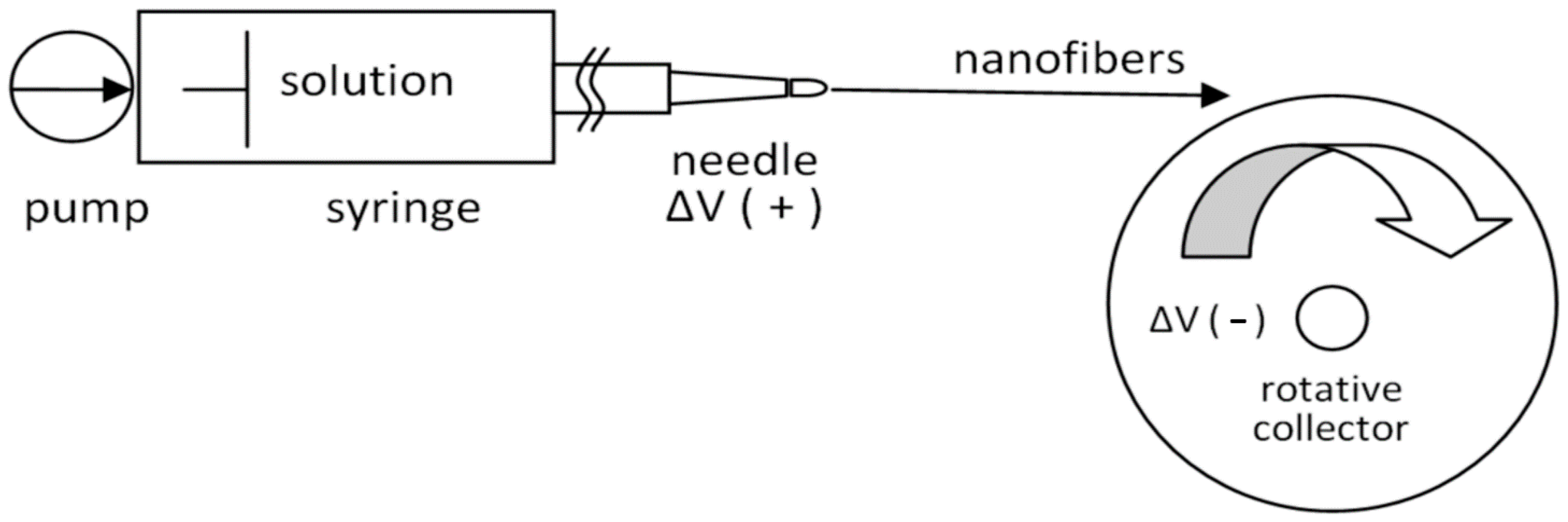
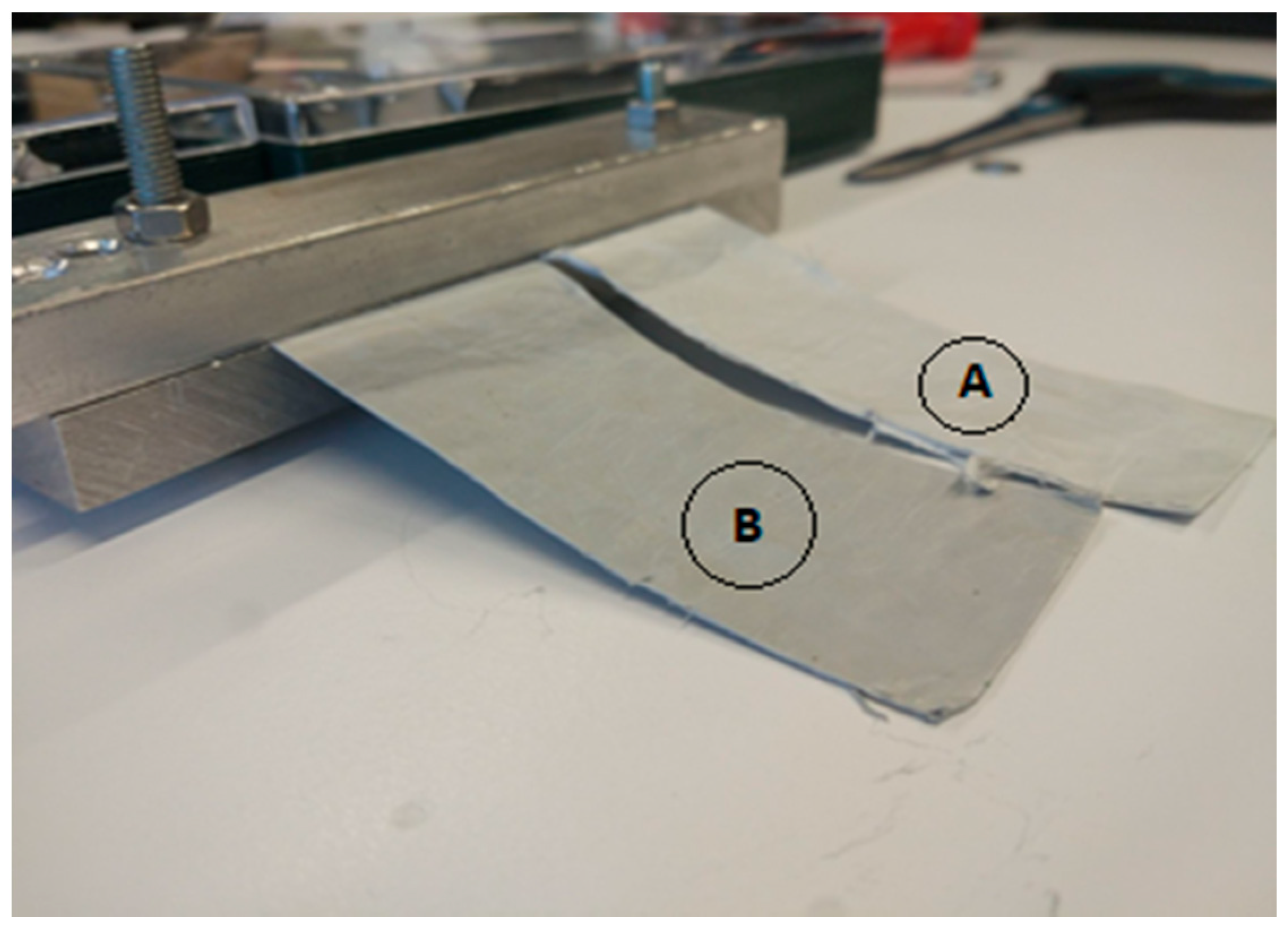
2.4. Electrospinning Process

Figure 1 depicts the electrospinning apparatus and the setup used. An amount of 7 mL of each dope solution was collected in a 10 mL syringe. The syringe was mounted on the top of the apparatus and was connected to an electric linear actuator, to pump the fluid. The actuator forces the solution to flow in the connection tube to the apparatus chamber. Here, the tube and needle were connected using an alligator clip to the electrical potential difference generator. Between the syringe and the metal needle, a tube with 1 m length and 1 mm diameter was placed. The chamber also contained a rotative collector that was electrically grounded. The distance between the needle and the rotative collector was about 20 cm. The apparatus was provided with an LED lamp used both for illumination and temperature regulation. The whole system was controlled through dedicated software.
To start the process, the volume flow rate was set to 0.8 mL/h in the tube; the collector speed was set to 8 m/s and the potential difference to 16 kV. As soon as the first drop of solution pours from the needle, the electric field attracts it, forming the nanofilament flow that ends on the foil covering on the spinning collector. The apparatus was operated continuously for 6 h and then stopped. The aluminum foil with the fiber mat was cut and removed from the collector. Then, the nanofiber mat was accurately separated from the foil and stored.

2.5. Stabilization/Cyclization

Nanofiber mats were subsequently cut into smaller stripes with a scalpel and prepared for the stabilization process. Stabilization is the fundamental intermediate step of carbon fiber production. Stabilization or cyclization consists in a controlled heat treatment at a temperature between 180 °C and 300 °C [34]. As a result, the linear PAN molecular chains convert into cyclic structures or ladder-like structures, which help to keep the fibers infusible and nonflammable when carbonized at higher temperatures [35]. The process starts clamping the pieces of the pre-cut fiber mats, using two aluminum clamps, as shown in Figure 2 (in the picture, only one side of the mat is clamped). Once both sides are clamped, the mats are placed in the oven for the first thermal treatment. Here, the metal clamps have two major roles: first, they keep the mats lifted for an even thermal treatment on both the mat faces; secondly, they keep the material slightly tensioned under its own weight, preventing excessive shrinkage during the heat treatment.
The stabilization method used was based on a stepwise increase in temperature. Tightened precursor stripes were put in a Thermo Scientific HeraTermTM oven. The heating program was set according to reference [34]: during the first 3 h, the temperature constantly increases until 250 °C is reached; then, the process is kept at 250 °C for 5 h, and finally cooled for 3 more hours until room temperature is reached.

2.6. Carbonization

The final process consists in the sample’s carbonization. This step provides the evaporation of the noncarbon compounds and therefore finalizes the carbon fibers production [35]. This thermal treatment occurred in a GeroTM 30–3000 °C furnace, controlled by a EurothermTM 3508 unit. Cyclized fibers were cut into smaller pieces, placed into graphite crucibles, and then put inside the furnace. Nitrogen was used as the process inert gas with a flow rate of 50 Nl/h. The heating speed was set to 5 °C/minute. After reaching 1700 °C, the temperature was kept constant for 1 h to assure the complete carbonization of the whole sample. Then, the process was stopped, leaving the chamber to naturally cool down. Carbonized fibers were later characterized with scanning electron microscopy.

2.7. Samples’ Characterization Techniques

The PAN and PAN-biochar electrospun fibers were analyzed through a combination of the following techniques.
-
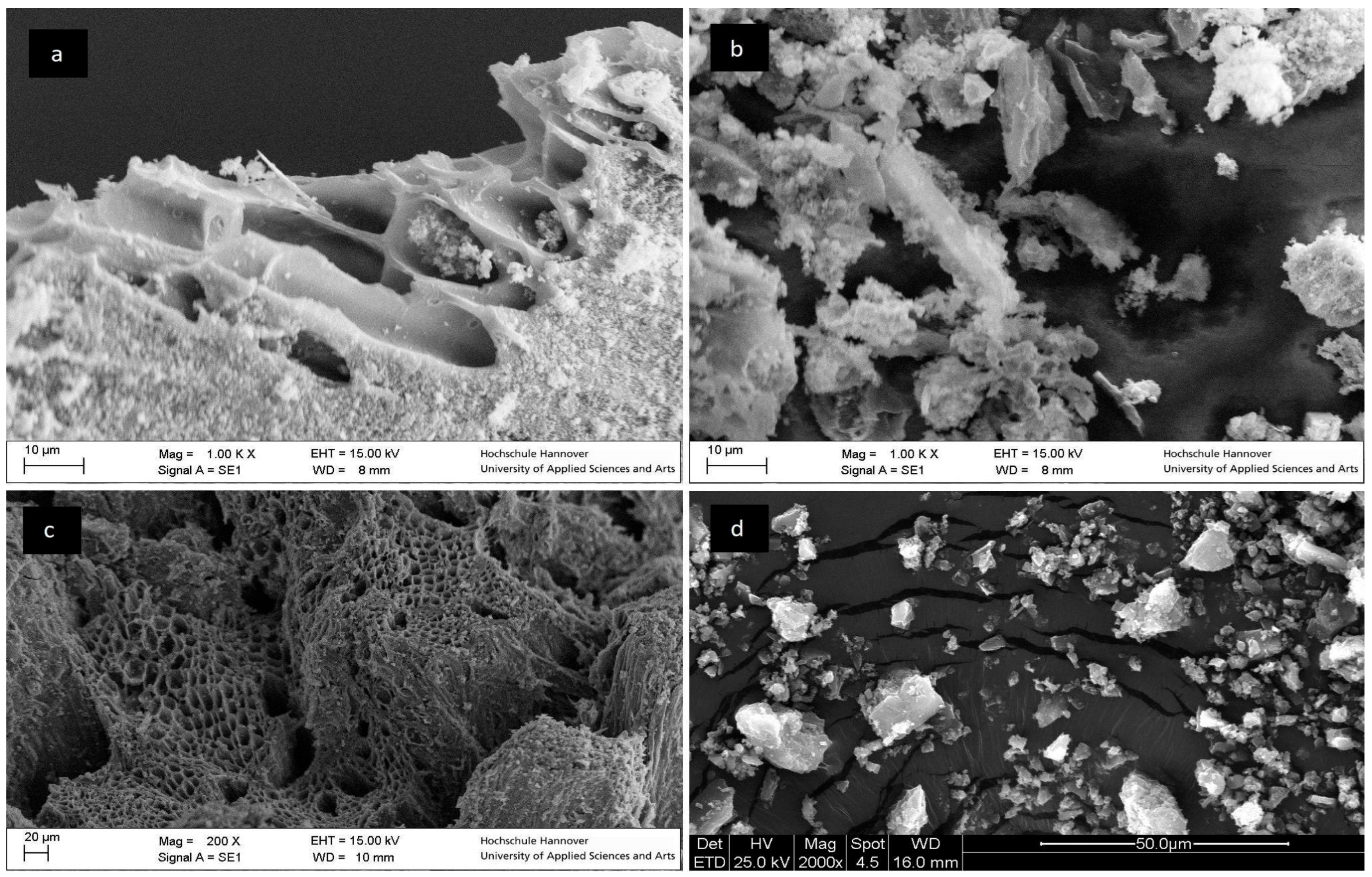
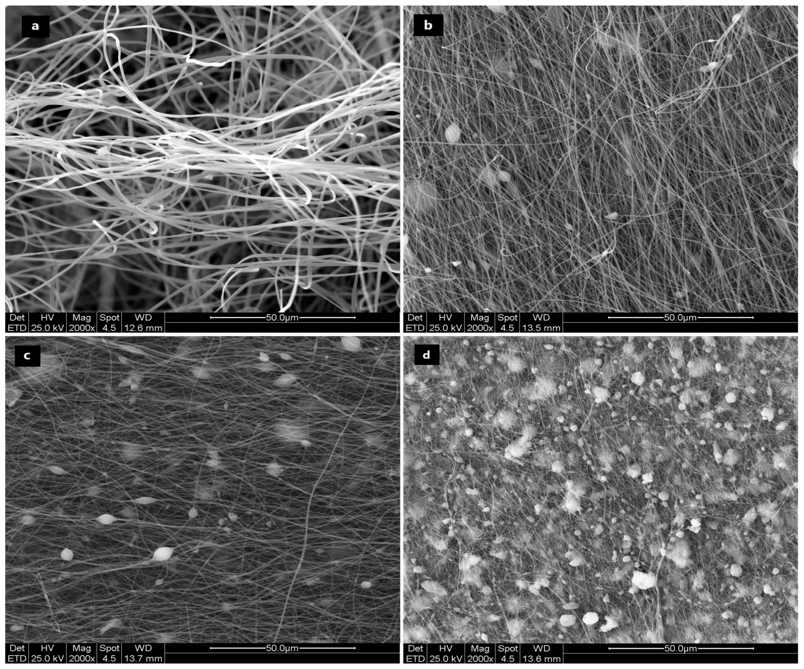
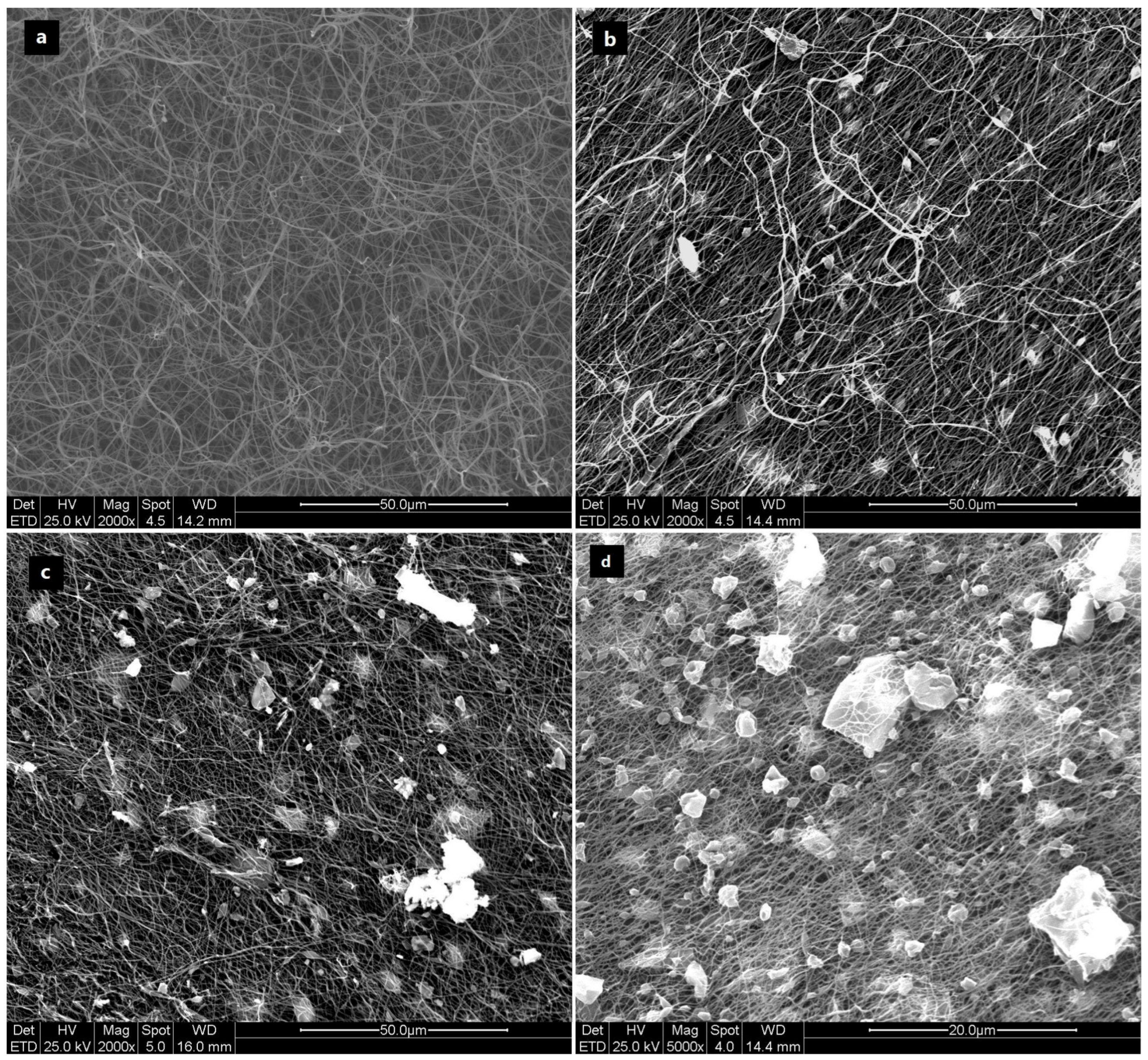
The Environmental Scanning Electron Microscope (ESEM, FEI Quanta-200) was used for microstructural characterizations. Scanning electron microscope imaging uses a focused electron beam to scan the sample surface. The signals that originate from the electron-surface interactions provide the information regarding the sample micromorphology. ESEM was used in high-vacuum mode, applying the secondary electron detector, Everhart–Thornley type (ETD), to obtain micro-morphological data on sample surfaces.
-
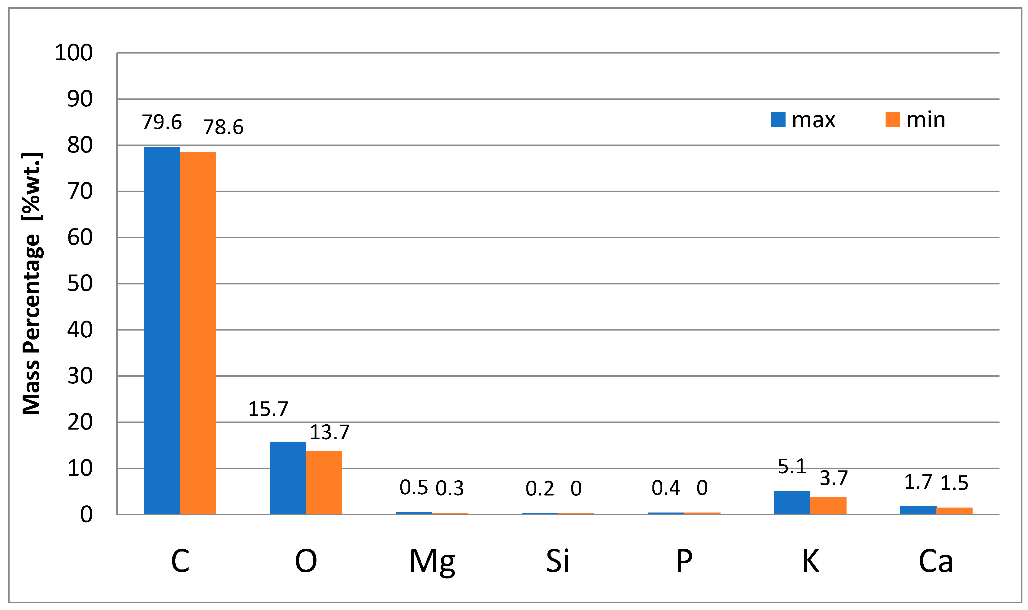
Energy-dispersive X-ray spectroscopy (X-EDS) was applied to carry out semi-quantitative chemical analysis. This analytical technique is often provided by the ESEM apparatus due to back-scattered electron imaging. X-EDS provides a chemical characterization of the sample, analyzing the specific electromagnetic emission spectrum, which identifies each element. Data were acquired and elaborated through X-EDS Oxford INCA-350 software. More spectra were acquired for each sample to obtain a significant statistical analysis. Chemical information about elemental composition was expressed as weight elemental percentage.
-
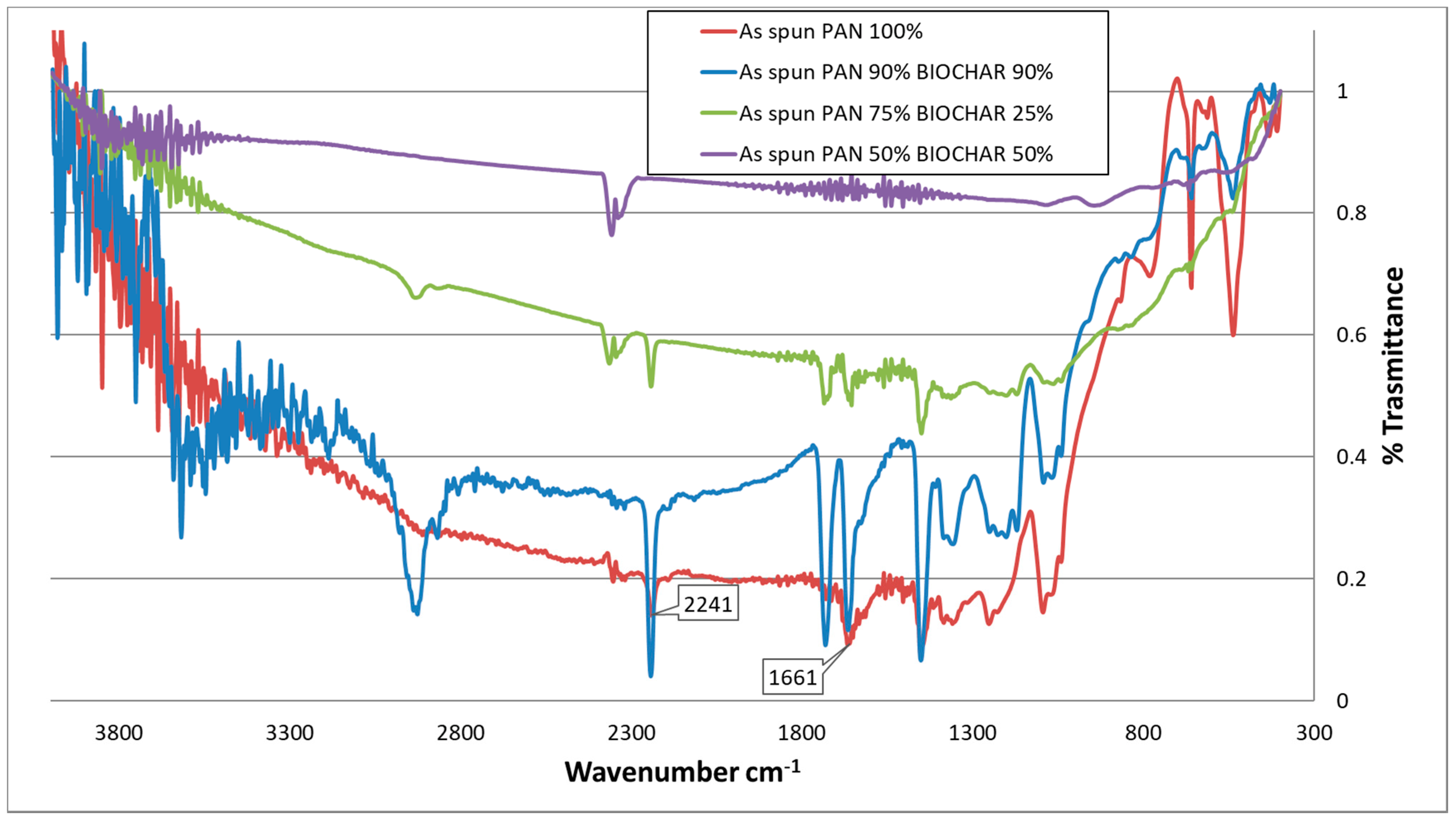
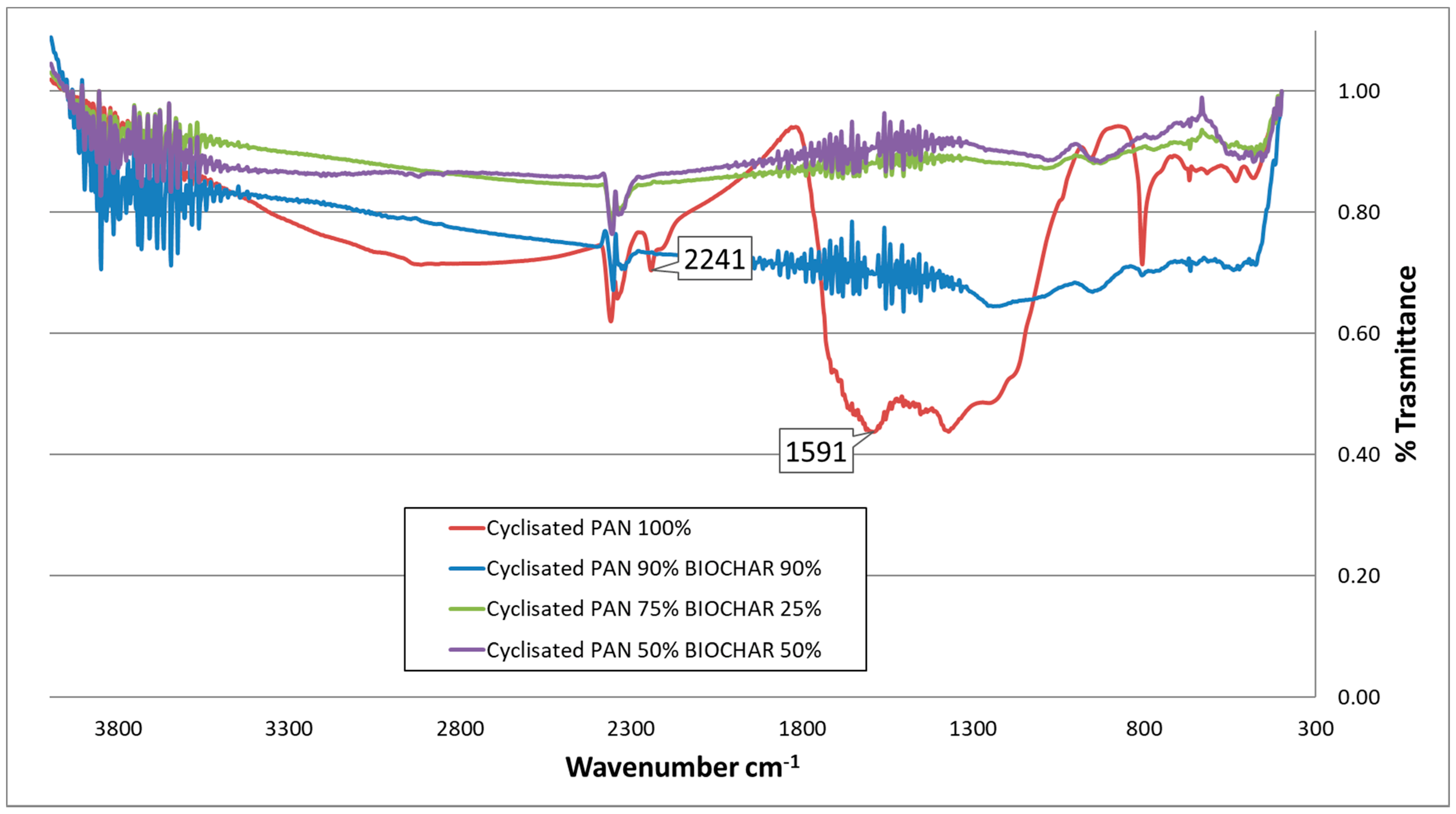
Fourier-transform infrared spectroscopy (FT-IR): measuring the absorption and emission infrared spectrum of the samples, it is possible to identify compounds, gaining fundamental information about the chemical bonds. The instrument used in this work was FT-IR (Bruker Tensor 27 IR). IR analysis was conducted at ACI-LUH, Hannover.

3. Results and Discussion

3.1. Biochar Analyses

Biochar from gasification was analyzed and its ultimate analysis is reported in Table 1. Carbon represented the most abundant element, followed by ashes [26], as previously mentioned, and the oxygen content can be back-calculated as a complementary value to reach 100%. The gasification temperatures adopted ranged from 600 °C up to 950 °C, and the average temperature considered was 750 °C. Particle distribution analysis of the “as-received” biochar is reported in Table 2.

Imaging of Prepared Biochar and Milled Biochar

Figure 3a shows the as-received char. It appeared covered with dust and soot. It is possible to notice that the soot and dust material was also present inside the pores of the structure. To select the finest powder, the material sifted under the 32-micron sieve was collected and analyzed with ESEM. It is possible to notice (Figure 3b) that the powder obtained from the “as-received” biochar still presented an extended number of impurities on its surface. The final goal of this work was to provide, through the char, a carbon source for the PAN electrospinning process. For this reason, impurities need to be completely avoided. Soot and dust materials have different compositions when compared to char: the ash content does not provide any carbon source, while the organic part (mostly polycyclic hydrocarbon) will behave differently from char in the process [1]. For these reasons, the simple direct use of the “as-received” sifted powder cannot be followed and the milling procedure does not solve the problem. In order to produce a cleaner powder, two possible approaches were followed: an attempt was made to mill the char particles, and then a second attempt preceded the milling process with a solvent cleaning stage.
It was decided to clean the biochar pellets in isopropyl alcohol before the milling process. After 20 h in isopropyl alcohol, the cleaned biochar morphology is depicted in Figure 3c. Biochar particles resulted cleaner from impurities in comparison with the ones that were not solvent-washed, and therefore, they were chosen to be further processed through milling and sifting. Once dried, clean biochar pellets were milled with the described process and then wet-sieved with isopropanol in a 32 µm sieve. The results are shown in Figure 3d. While, in Figure 3b, the powder was agglomerated, in Figure 3d, the powder was generally deagglomerated and single grains can be seen.
The powder composition was analyzed using EDS analysis. Figure 4 shows the results of the composition analysis, outlining the maximum and the minimum of amounts recorded for each element.

3.2. Imaging of PAN/Biochar Fibers though the Preparation Process

Biochar clean powder obtained from milling was mixed with PAN and dissolved in DMF, as described in Section 2.3, to produce four dope solutions, with different percentages of biochar. Fibers were later characterized.

3.2.1. ESEM Imaging of “as-Spun” Fibers

Dope solutions were electrospun and analyzed with ESEM. Figure 5 shows that the fibers without biochar grains were smoother and more homogeneous in diameter compared to the biochar-additivated ones. Before this work, it was unclear the outcome of char additivation of dope solutions. The chance of not being capable of producing any fiber mat was confuted by the results shown here: biochar was successfully added to PAN fibers, producing large beads-like inclusions, compared to the PAN-only fibers that were under 1 micrometer in diameter. It can be qualitatively seen how the amount of biochar inclusions increased accordingly with the amount of biochar used in the solution that seemed to not affect the average diameter of the inclusions. Therefore, the dope solution preparation, as well as the spinning process, did not produce further agglomeration of the biochar particles. As a final general remark, during the investigation process, no breaking of the fibers in points close to the char inclusions was recorded, leading to the conclusion that the char particles were well combined in the fiber structure. Similar results were found by Nan et al. [13] that defined the obtained biochar-PAN fibers as “morphologically non-uniform”.
In Figure 5, it can be observed how the biochar beads dispersed between the fibers. The mean dimension of biochar beads was 6–7 µm even if the sieve mesh dimension was 32 µm. This proves that the milling process was effective in reducing the biochar particle size significantly below the sieving limit. Generally, fibers were mostly aligned, as expected from the process with the rotating collector. ESEM imaging of cyclized fibers was not relevant for the analysis, as cyclization was a middle-step process.

3.2.2. ESEM Imaging of Carbonized Fibers

In Figure 6, it can be seen that the grains were well dispersed inside the fiber mat, and in this composition, they occupied a large portion of the material mass. Fiber diameters remained around 1 µm for all the investigated cases. The dimension of biochar beads was calculated with ImageJ software, and it resulted in below 10 microns in all observed cases. The 50–50% sample, that represented a bold substitution rate, still showed the fiber completely formed, and the biochar particles seemed blended to the carbon structure of the fibers.
As a primary result, it can be seen from the pictures that biochar beads were successfully jointed to the fibers and that they overcame the thermal treatments. After the carbonization process, the particles did not further dissolve in the carbon fibers structure. The fibers observed with the ESEM resembled a lattice structure with biochar grains dispersed and fixed in position. The same results were found by Nan et al. [13] incorporating the char particles in PAN fibers: “after the thermal treatments of stabilization and carbonization, the resulting carbon nanofibers well-retained overall morphological structures of their precursor nanofibers”.

3.2.3. EDS Analyses of “as-Spun” Fibers

As expected, PAN fibers were formed mainly by carbon, nitrogen, and oxygen. EDS analysis is incapable of detecting hydrogen, but it is known that it was also present due to the polymer composition.
Figure 7 presents the results of the analysis. While the biochar percentage grew, the percentage of detected inorganics grows as well. It can be noticed that potassium in 90/10, 75/25, and 50/50 solutions grew continuously, and the calcium content increased as well in the 75/25 and then in the 50/50 samples. Aluminum and gold derived from the metallization process for the ESEM analysis [36]. Nitrogen and oxygen probably derived from PAN. The 50/50 sample showed various other elements that probably belonged to the biochar ashes. It can be seen how potassium and calcium were the most prevalent; these elements came from the initial biomass composition. In this work, the biomass used to produce the char consisted in vineyard pruning wood pellets. This fuel is known to have a significant K and Ca content [37].

3.2.4. EDS Analyses of Carbonized Fibers

The carbonized fibers composition was simpler than that of the “as-spun” samples. Oxides, metals, and other inorganic compounds belonging to the biochar ashes, which were detected in the “as spun” fibers, drastically dropped in the carbonized samples.
The EDS analyses suggest that these compounds probably evaporated in the furnace due to the severe thermal treatment, performed at 1700 °C, as expected and confirmed also by the literature for various inorganics [38,39]. The fiber carbon content peaked after the process, reaching values from 97.2% to 100%, and the remaining percentage was covered by metals used to perform the ESEM analysis (gold and aluminum). Silicium was present only in traces. Figure 8 presents the results of the analysis.
Therefore, it can be assessed that the carbonization process was effective either with only PAN fibers or with composite PAN-biochar fibers. Ashes were an unavoidable part of the biomass-derived char. This study started with the concern that these inorganic compounds would have negatively affected the final composition of the fibers, reducing their purity. The results proved the opposite, showing almost carbon-pure thermal-treated spun material.

3.2.5. FT-IR Spectroscopy of “as-Spun” and Cyclized Fibers

Stabilized/cyclized samples were analyzed with an IR spectrometer. Figure 9 reports the as-spun spectra. The spectra for the 100% PAN fiber can be compared to the literature [40] to properly assess if the polymerization occurred correctly. The peak at approximately 2241 cm−1 represents the triple bond (C≡N), as described in [41]. Kim et al. [41] also referred to the peak at 1668 cm−1 (1661 in the figure) to the precursor. As expected, the choice to use high-temperature gasification biochar impacted the results reported in Figure 9. Gasification biochar was produced in high-temperature environments (starting from 900–1100 °C in the combustion zone, then decreasing to 600 °C at the end of the reduction zone), and these conditions led to a structure where all of the functional groups left the surface. This can be observed by the general and diffuse decrease in the spectra transmittance (therefore, an increase in the material absorbance) as the amount of biochar in the preparation increased. Similar results were reported by Taheran et al. where active char was used as an additive in PAN fibers [20].
The spectra of the cyclized PAN (Figure 10) showed a reduction in the above-mentioned peak corresponding to the C≡N bond, and an evolution of the peak at ~1591 cm−1 was observed. This peak corresponds to the C=N band. This indicates that the cyclization took place and a ladder-like structure was formed [42]. This structure enables the PAN fibers to withstand the high-temperature carbonization temperature [43]. This phenomenon was less and less pronounced as the biochar share in the solution increased due to the absorptive behavior previously described. Biochar had two major effects on the spectra: on the one hand, biochar “diluted” the amount of PAN, thus reducing the signal of the peaks that can be easily recognized in the 100% spectrum. Secondly, the char structure introduced a series of noises above 3000 cm−1 and between 1300 and 1800 cm−1. The literature review described the biochar-induced noises as associated with different groups [44,45]. As reported by [46], the presence of several peaks in the range of 3400–4000 cm−1 may be assigned to the water absorbed. The spectra recorded in this work did not show sharp peaks in that area, but a general noise of the signal. Biochar had strong hygroscopic behavior, and the shares of biochar in the material may have adsorbed large amounts of water, leading to high noises in the test.

4. Conclusions

This work laid the basis for investigating possible roles of biomass-derived gasification char as a carbon source in electrospun carbon fibers. A correct preparation of the material consists in a combination of solvent cleaning, milling, and sifting. The milling process was proven to effectively reduce the average char particle diameter below the 32 µm mesh used for sieving. Four different solutions were prepared for electrospinning: 100% PAN; 90% PAN-10% biochar; 75% PAN-25% biochar; 50% PAN-50% biochar. All the solutions tested successfully produced a fiber mat. The materials produced were then processed through cyclization (5 h at 250 °C) and carbonization (1 h at 1700 °C). Biochar particles embedded in the material resulted in an average size that differed extremely from the fiber diameter. An increase in the biochar share in the electrospinning solution resulted in a final material where the filament part was less and less present due to the inclusions. Regardless of the bulk presence of the char inclusions, all the materials prepared stood the thermal treatments with no physical consequences. IR spectra showed a correct cyclization of the samples even if the biochar shares introduced new noises in the analyses. The original biochar showed significant Ca and K contents typical of vine pruning biomass. These elements drastically reduced their content during the high-temperature carbonization process. As concluding remarks, it is possible to observe that the biochar pores show walls as thin as the desirable final fiber is. There is then a chance for future works to further reduce the particle size. A possible solution takes advantage of cryogenic milling processes that should better perform in terms of final powder dimension.

Author Contributions

Conceptualization, A.S., S.P., F.R. and G.A.; methodology, F.R., A.B.A. and R.S.; validation, S.P.; investigation, A.S.; data curation, A.S., F.R., A.B.A., R.S. and G.A.; writing S.P., A.S. and G.A.; supervision, G.A. and F.R.; project administration, F.R. All authors have read and agreed to the published version of the manuscript.

Funding

This research received no external funding.

Institutional Review Board Statement

Not applicable.

Informed Consent Statement

Not applicable.

Data Availability Statement

Not applicable.

Conflicts of Interest

The authors declare no conflict of interest.

References

  1. Basu, P. Biomass Gasification, Pyrolysis and Torrefaction: Practical Design and Theory, 3rd ed.; Academic Press: Cambridge, MA, USA; Elsevier: London, UK, 2018. [Google Scholar]
  2. Piccolo, F.; Andreola, F.; Barbieri, L.; Lancellotti, I. Synthesis and Characterization of Biochar-Based Geopolymer Materials. Appl. Sci. 2021, 11, 10945. [Google Scholar] [CrossRef]
  3. Farges, R.; Gharzouni, A.; Ravier, B.; Jeulin, P.; Rossignol, S. Insulating foams and dense geopolymers from biochar by-products. J. Ceram. Sci. Technol. 2018, 9, 193–200. [Google Scholar] [CrossRef]
  4. Araya, M.; Rivas, J.; Sepúlveda, G.; Espinoza-González, C.; Lira, S.; Meynard, A.; Blanco, E.; Escalona, N.; Ginocchio, R.; Garrido-Ramírez, E.; et al. Effect of Pyrolysis Temperature on Copper Aqueous Removal Capability of Biochar Derived from the Kelp Macrocystis pyrifera. Appl. Sci. 2021, 11, 9223. [Google Scholar] [CrossRef]
  5. Mansouri, F.E.; Farissi, H.E.; Zerrouk, M.H.; Cacciola, F.; Bakkali, C.; Brigui, J.; Lovillo, M.P.; Esteves da Silva, J.C.G. Dye Removal from Colored Textile Wastewater Using Seeds and Biochar of Barley (Hordeum vulgare L.). Appl. Sci. 2021, 11, 5125. [Google Scholar] [CrossRef]
  6. Enaime, G.; Lübken, M. Agricultural Waste-Based Biochar for Agronomic Applications. Appl. Sci. 2021, 11, 8914. [Google Scholar] [CrossRef]
  7. Ali, L.; Xiukang, W.; Naveed, M.; Ashraf, S.; Nadeem, S.M.; Haider, F.U.; Mustafa, A. Impact of Biochar Application on Germination Behavior and Early Growth of Maize Seedlings: Insights from a Growth Room Experiment. Appl. Sci. 2021, 11, 11666. [Google Scholar] [CrossRef]
  8. Liou, Y.; Huang, W. A Process for Preparing High Graphene Sheet Content Carbon Materials from Biochar Materials. In Electroplating of Nanostructures; Aliofkhazraei, M., Ed.; IntechOpen: London, UK, 2015; Available online: https://www.intechopen.com/chapters/48922 (accessed on 14 April 2022). [CrossRef] [Green Version]
  9. Saha, J.K.; Dutta, A. A Review of Graphene: Material Synthesis from Biomass Sources. Waste Biomass Valorization 2022, 13, 1385–1429. [Google Scholar] [CrossRef]
  10. Tang, J.; Lv, H.; Gong, Y.; Huang, Y. Preparation and characterization of a novel graphene/biochar composite for aqueous phenanthrene and mercury removal. Bioresour. Technol. 2015, 196, 355–363. [Google Scholar] [CrossRef]
  11. Moulefera, I.; Trabelsi, M.; Mamun, A.; Sabantina, L. Electrospun Carbon Nanofibers from Biomass and Biomass Blends—Current Trends. Polymers 2021, 13, 1071. [Google Scholar] [CrossRef]
  12. Vélez, D.C.P.; Magalhães, W.L.E.; Capobianco, G. Carbon fiber from fast pyrolysis bio-oil. Sci. Technol. Mater. 2018, 30, 16–22. [Google Scholar] [CrossRef]
  13. Nan, W.; Zhao, Y.; Ding, Y.; Shende, A.R.; Fong, H.; Shende, R.V. Mechanically flexible electrospun carbon nanofiber mats derived from biochar and polyacrylonitrile. Mater. Lett. 2017, 205, 206–210. [Google Scholar] [CrossRef]
  14. Li, X.; Xu, T.; Liang, Z.; Amar, V.S.; Huang, R.; Maddipudi, B.K.; Shende, R.V.; Fong, H. Simultaneous Electrospinning and Electrospraying for the Preparation of a Precursor Membrane Containing Hydrothermally Generated Biochar Particles to Produce the Value-Added Product of Carbon Nanofibrous Felt. Polymers 2021, 13, 676. [Google Scholar] [CrossRef] [PubMed]
  15. Tomczyk, A.; Sokołowska, Z.; Boguta, P. Biochar physicochemical properties: Pyrolysis temperature and feedstock kind effects. Rev. Environ. Sci. Bio. Technol. 2020, 19, 191–215. [Google Scholar] [CrossRef] [Green Version]
  16. Ramakrishna, S. An Introduction to Electrospinning and Nanofibers; World Scientific Publishing Co. Pte. Ltd.: Danvers, MA, USA, 2005; pp. 5–300. [Google Scholar]
  17. Lee, C.S. Carbon Nanofibers Synthesis, Applications and Performance, 1st ed.; Nova Science Pub Inc.: New York, NY, USA, 2018; pp. 4–5. [Google Scholar]
  18. Figueiredo, J.L.; Bernardo, C.A.; Baker, R.T.K.; Hüttinger, K.J. Carbon Fibers Filaments and Composites, 1st ed.; Springer: Berlin, Germany, 1989; pp. 50–250. [Google Scholar]
  19. Dang, W.; Liu, J.; Wang, X.; Yan, K.; Zhang, A.; Yang, J.; Chen, L.; Liang, J. Structural Transformation of Polyacrylonitrile (PAN) Fibers during Rapid Thermal Pretreatment in Nitrogen Atmosphere. Polymers 2020, 12, 63. [Google Scholar] [CrossRef] [Green Version]
  20. Zhang, M.; Song, W.; Tang, Y.; Xu, X.; Huang, Y.; Yu, D. Polymer-Based Nanofiber—Nanoparticle Hybrids and Their Medical Applications. Polymers 2022, 14, 351. [Google Scholar] [CrossRef]
  21. Khan, Z.; Kafiah, F.; Shafi, H.Z.; Nufaiei, F.; Furquan, S.A.; Matin, A. Morphology, Mechanical Properties and Surface Characteristics of Electrospun Polyacrylonitrile (PAN) Nanofiber Mats. Int. J. Adv. Eng. Nano Technol. 2015, 2, 15–22. [Google Scholar]
  22. Callister, W.D., Jr.; Rethwisch, D.G. Fundamentals of Materials Science and Engineering, 1st ed.; John Wiley & Sons: New York, NY, USA, 2001; pp. 70–163. [Google Scholar]
  23. Qin, Y. Medical Textile Materials; Woodhead Publishing—Elsevier: Amsterdam, The Netherlands, 2016; pp. 1–266. [Google Scholar] [CrossRef]
  24. Gulrajani, M.L. Advances in the Dyeing and Finishing of Technical Textiles, 1st ed.; Woodhead Publishing—Elsevier: Amsterdam, The Netherlands, 2013. [Google Scholar]
  25. Morgan, P. Carbon Fibers and Their Composites; Taylor and Francis CRC Press: Boca Raton, FL, USA, 2005; pp. 340–621. [Google Scholar]
  26. Puglia, M.; Torri, G.; Martinelli, V.; Tartarini, P. Vine Prunings Agro-Energetic Chain: Experimental and Economical Assessment of Vine Pellets Use in Gasification Power Plants. In Proceedings of the 28th European Biomass Conference and Exhibition, Online, 6–9 July 2020. [Google Scholar]
  27. Allesina, G.; Pedrazzi, S. Barriers to Success: A Technical Review on the Limits and Possible Future Roles of Small Scale Gasifiers. Energies 2021, 14, 6711. [Google Scholar] [CrossRef]
  28. All Power Labs Inc. PP30 Gasifier Datasheet. 2021. Available online: https://www.allpowerlabs.com/pp30-power-pallet (accessed on 14 April 2022).
  29. Pedrazzi, S.; Santunione, G.; Mustone, M.; Cannazza, G.; Citti, C.; Francia, E.; Allesina, G. Techno-economic study of a small scale gasifier applied to an indoor hemp farm: From energy savings to biochar effects on productivity. Energy Convers. Manag. 2021, 228, 113645. [Google Scholar] [CrossRef]
  30. Pedrazzi, S.; Allesina, G.; Sebastianelli, L.; Puglia, M.; Morselli, N.; Tartarini, P. Chemically enhanced char for syngas filtering purposes. In Proceedings of the 26th European Biomass Conference and Exhibition Proceedings, Copenhagen, Denmark, 14–17 May 2018. [Google Scholar]
  31. Tsekos, C.; Anastasakis, K.; Schoenmakers, P.L.; De Jong, W. PAH sampling and quantification from woody biomass fast pyrolysis in a pyroprobe reactor with a modified tar sampling system. J. Anal. Appl. Pyrolysis 2020, 147, 104802. [Google Scholar] [CrossRef]
  32. Neeft, J.P.A.; Knoef, H.A.M.; Buffinga, G.J.; Zielke, U.; Sjöström, K.; Brage, C.; Hasler, P.; Smell, P.A.; Suomalainen, M.; Dorrington, M.A.; et al. Guideline for Sampling and Analysis of Tars and Particles in Biomass Producer Gases. In Progress in Thermochemical Biomass Conversion; Bridgwater, A.V., Ed.; Blackwell Science Ltd.: London, UK, 2001; pp. 162–175. [Google Scholar] [CrossRef]
  33. Little, A.; Cash, M. High Temperature Corrosion of Silicon-Based Ceramics in a Simulated Coal Gasification Environment. In Proceedings of the CORROSION 98, San Diego, CA, USA, 22–27 March 1998. [Google Scholar]
  34. Rahaman, M.S.A.; Ismail, A.F.; Mustafa, A. A review of heat treatment on polyacrylonitrile fiber. Polym. Degrad. Stab. 2007, 92, 1421–1432. [Google Scholar] [CrossRef] [Green Version]
  35. Ali, A.B.; Dreyer, B.; Renz, F.; Tegenkamp, C.; Sindelar, R. Electrospun Polyacrylonitrile Based Carbon Nanofibers: The Role of Creep Stress towards Cyclization and Graphitization. J. Mater. Sci. Eng. 2018, 7, 1000493. [Google Scholar] [CrossRef]
  36. Juhász, L.; Moldován, K.; Gurikov, P.; Liebner, F.; Fábián, I.; Kalmár, J.; Cserháti, C. False Morphology of Aerogels Caused by Gold Coating for SEM Imaging. Polymers 2021, 13, 588. [Google Scholar] [CrossRef] [PubMed]
  37. Di Blasi, C.; Buonanno, F.; Branca, C. Reactivities of some biomass chars in air. Carbon 1999, 37, 1227–1238. [Google Scholar] [CrossRef]
  38. Guizani, C.; Jeguirim, M.; Valin, S.; Limousy, L.; Salvador, S. Biomass Chars: The Effects of Pyrolysis Conditions on Their Morphology, Structure, Chemical Properties and Reactivity. Energies 2017, 10, 796. [Google Scholar] [CrossRef] [Green Version]
  39. Chen, S.; Huang, H.; Li, Y.; Ma, T. A facile and general procedure to hyperporous carbons: Carbonization of organic zinc salts. Mater. Today Energy 2020, 17, 100446. [Google Scholar] [CrossRef]
  40. Taheran, M.; Naghdi, M.; Brar, S.K.; Knystautas, E.; Verma, M.; Surampalli, R.Y.; Valero, J.R. Development of adsorptive membranes by confinement of activated biochar into electrospun nanofibers. Beilstein J. Nanotechnol. 2016, 7, 1556–1563. [Google Scholar] [CrossRef] [Green Version]
  41. Kim, S.; Chung, Y.S.; Choi, H.S.; Jin, F.L.; Park, S.J. Preparation and Characterization of PAN-based Superfined Carbon Fibers for Carbon-paper Applications. Bull. Korean Chem. Soc. 2013, 34, 3733–3737. [Google Scholar] [CrossRef] [Green Version]
  42. Ali, A.B.; Slawig, D.; Schlosser, A.; Koch, J.; Bigall, N.C.; Renz, F.; Tegenkamp, C.; Sindelar, R. Polyacrylonitrile (PAN) based electrospun carbon nanofibers (ECNFs): Probing the synergistic effects of creep assisted stabilization and CNTs addition on graphitization and low dimensional electrical transport. Carbon 2021, 172, 283–295. [Google Scholar] [CrossRef]
  43. Ali, A.B.; Renz, F.; Koch, J.; Tegenkamp, C.; Sindelar, R. Graphene Nanoplatelet (GNPs) Doped Carbon Nanofiber (CNF) System: Effect of GNPs on the Graphitic Structure of Creep Stress and Non-Creep Stress Stabilized Polyacrylonitrile (PAN). Nanomaterials 2020, 10, 351. [Google Scholar] [CrossRef] [Green Version]
  44. Li, X.; Song, Y.; Bian, Y.; Wang, F.; Gu, C.; Yang, X.; Jiang, X. Effects of root exudates on the sorption of polycyclic aromatic hydrocarbons onto biochar. Environ. Pollut. Bioavailab. 2019, 31, 156–165. [Google Scholar] [CrossRef]
  45. Behazin, E.; Ogunsona, E.; Rodriguez-Uribe, A.; Mohanty, A.K.; Misra, M.; Anyia, A.O. Mechanical, Chemical, and Physical Properties of Wood and Perennial Grass Biochars for Possible Composite Application. Bioresources 2016, 11, 1334–1348. [Google Scholar] [CrossRef]
  46. Šupić, S.; Malešev, M.; Radonjanin, V.; Bulatović, V.; Milović, T. Reactivity and Pozzolanic Properties of Biomass Ashes Generated by Wheat and Soybean Straw Combustion. Materials 2021, 14, 1004. [Google Scholar] [CrossRef] [PubMed]
Figure 1. Electrospinning apparatus scheme.
Applsci 12 04441 g001
Figure 2. Image of 25% biochar fibers (A) and 10% biochar fibers (B) clamped on one side before stabilization.
Applsci 12 04441 g002
Figure 3. (a) Micro-morphological details from ESEM analysis on “as-received” biochar grain 1000× magnification; (b) sifted ”as-received” biochar powder, ESEM, 1000× magnification; (c) cleaned biochar pellet surface, ESEM, 200× magnification; (d) biochar particles after cleaning and sieving processes (applying 32 µm mesh).
Applsci 12 04441 g003
Figure 4. EDS analyses of cleaned and milled biochar pellets, and mass percentages of the detected elements. Maximum and minimum values obtained on three repeated spectra on the same sample are shown.
Applsci 12 04441 g004
Figure 5. ESEM imaging of the “as-spun” fibers: (a) 100% PAN; (b) 90% PAN-10% biochar; (c) 75% PAN-25% biochar; (d) 50% PAN-50% biochar.
Applsci 12 04441 g005
Figure 6. ESEM imaging of the carbonized fibers: (a) 100% PAN; (b) 90% PAN-10% biochar; (c) 75% PAN-25% biochar; (d) 50% PAN-50% biochar.
Applsci 12 04441 g006
Figure 7. EDS analyses of “as-spun” fibers, and mass percentages of the detected elements: (a) 100% PAN; (b) 90% PAN-10% biochar; (c) 75% PAN-25% biochar; (d) 50% PAN-50% biochar.
Applsci 12 04441 g007
Figure 8. EDS analyses of carbonized fibers, and mass percentages of the detected elements.
Applsci 12 04441 g008
Figure 9. IR spectrum of “as-spun” fibers.
Applsci 12 04441 g009
Figure 10. IR spectra of “cyclized” fibers.
Applsci 12 04441 g010
Table 1. Ultimate analysis of dry vine pruning biochar.
% Ash% C% H % N% S
Vine prunings biochar32.4867.780.820.57N.D.
Table 2. Particle size distribution of “as-received” biochar.
Size:>710 µm500–710 µm125–500 µm 63–125 µm32–63 µm<32 µm
mass %71.447.1113.222.42.43.2
Publisher’s Note: MDPI stays neutral with regard to jurisdictional claims in published maps and institutional affiliations.

