
Magnetic Interference Analysis and Compensation Method of Airborne Electronic Equipment in an Unmanned Aerial Vehicle


Abstract
:1. Introduction
2. Related Work
2.1. T–L Model
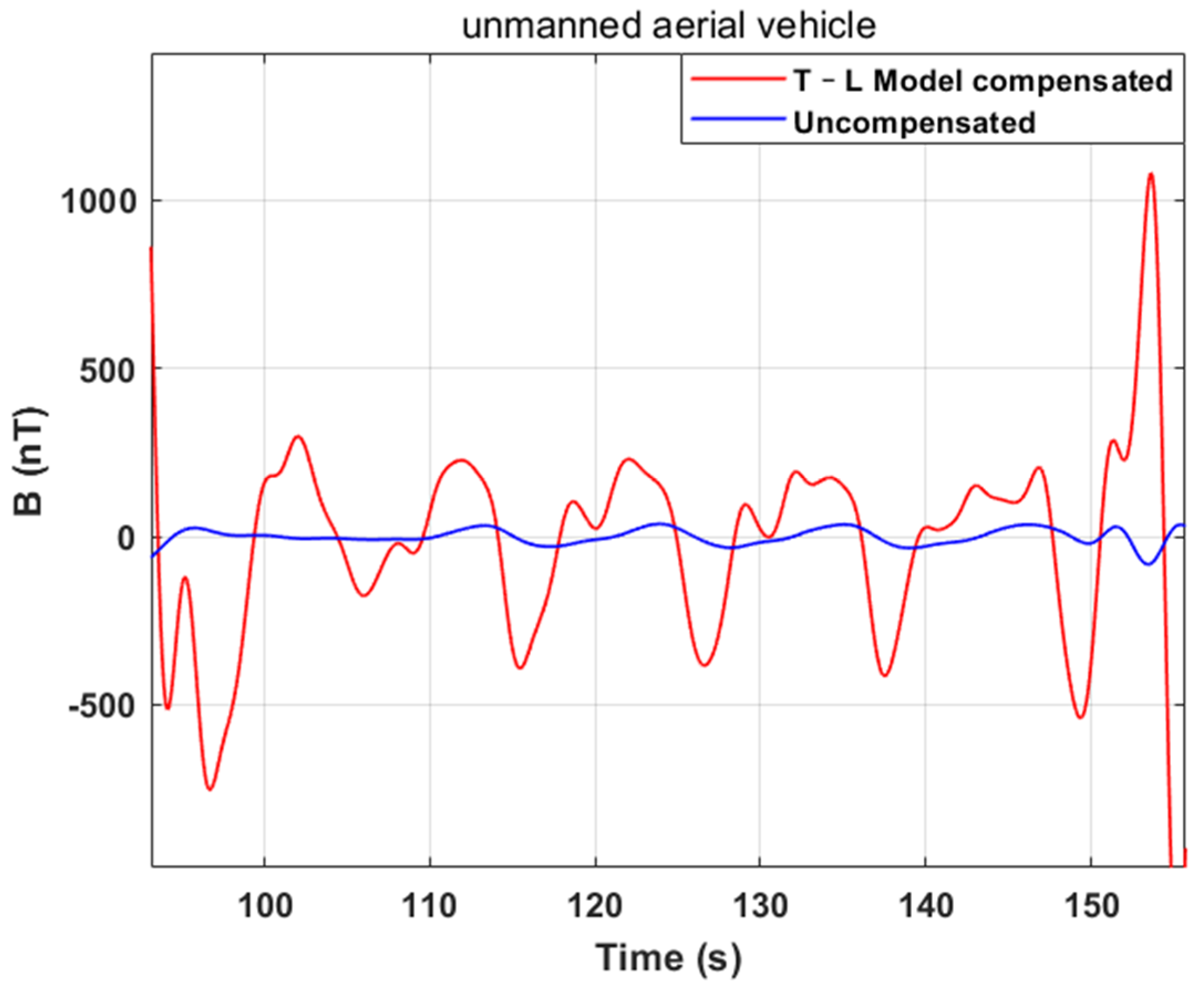
2.2. Comparison of T–L Model Compensation Effects
3. Theoretical Analysis and Experiment
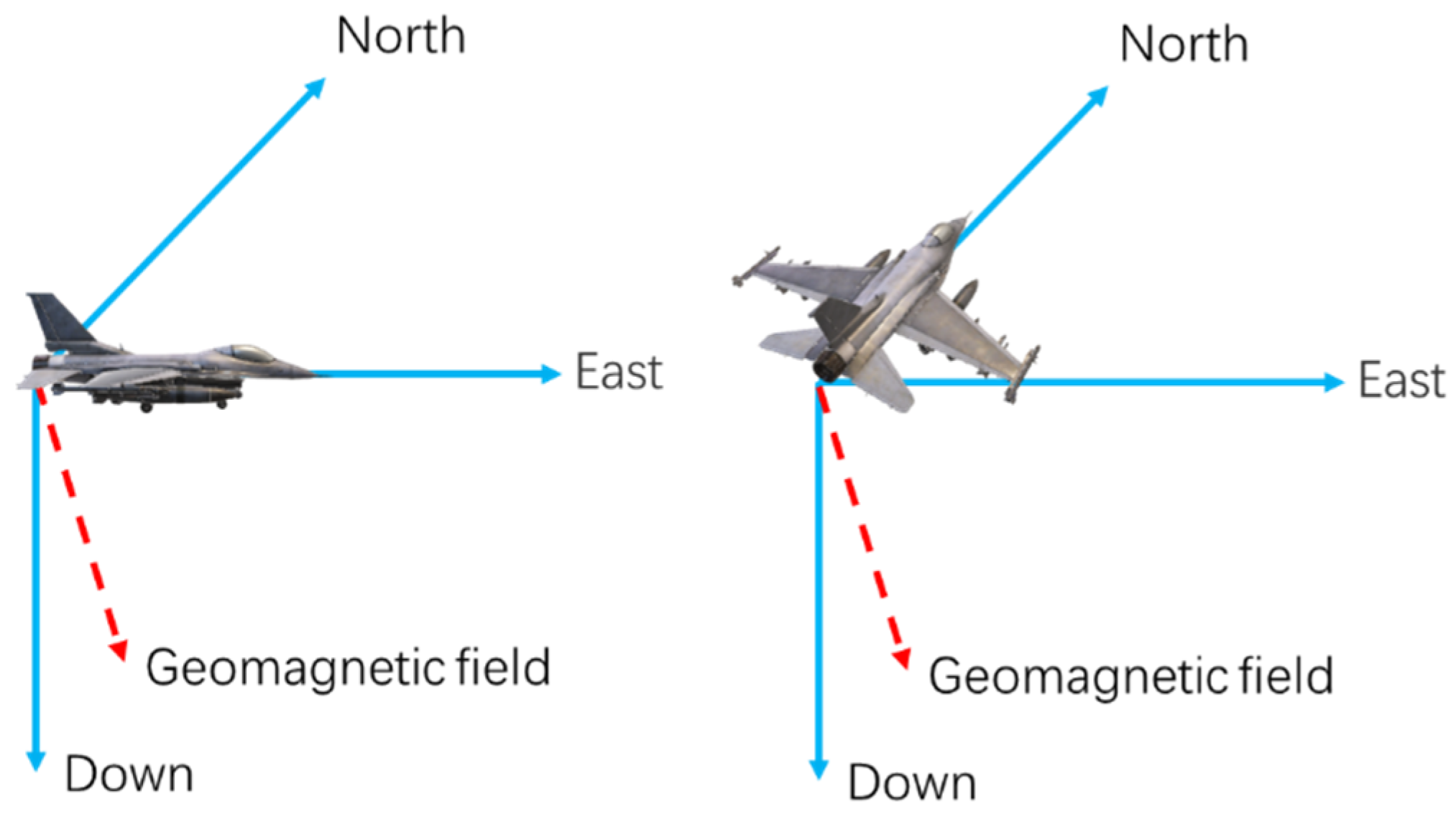
3.1. Theoretical Analysis
3.2. Experiment
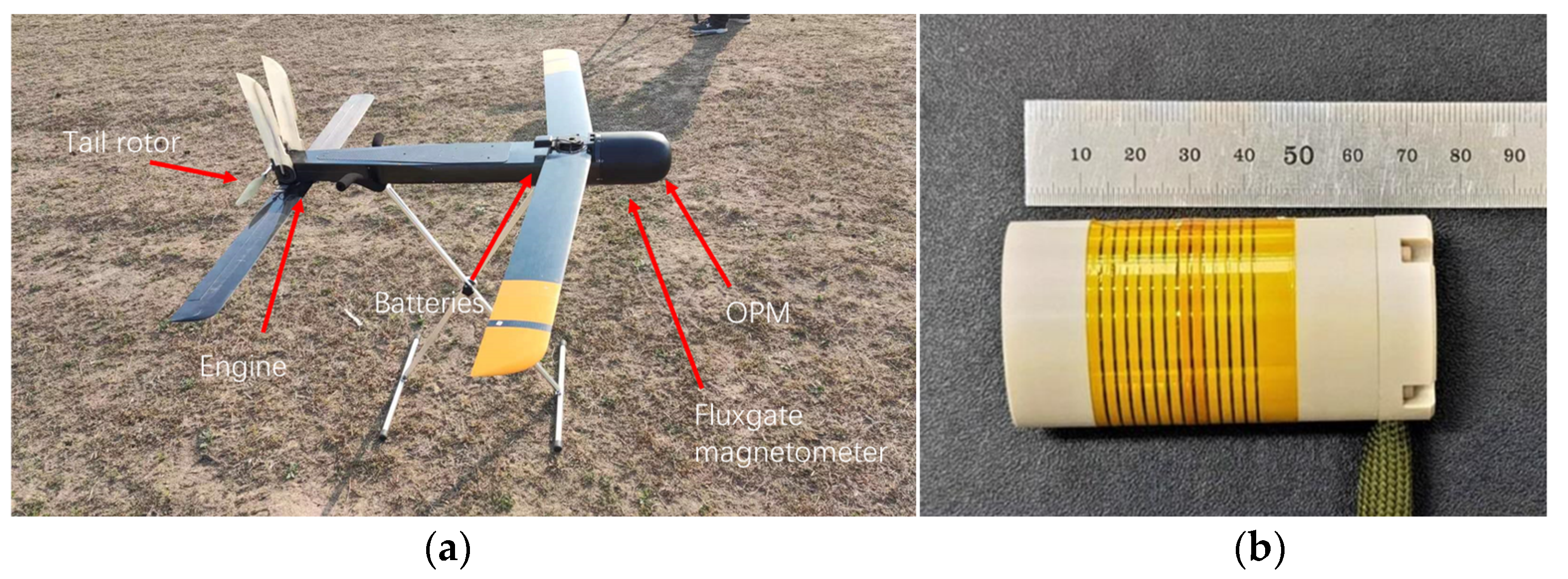
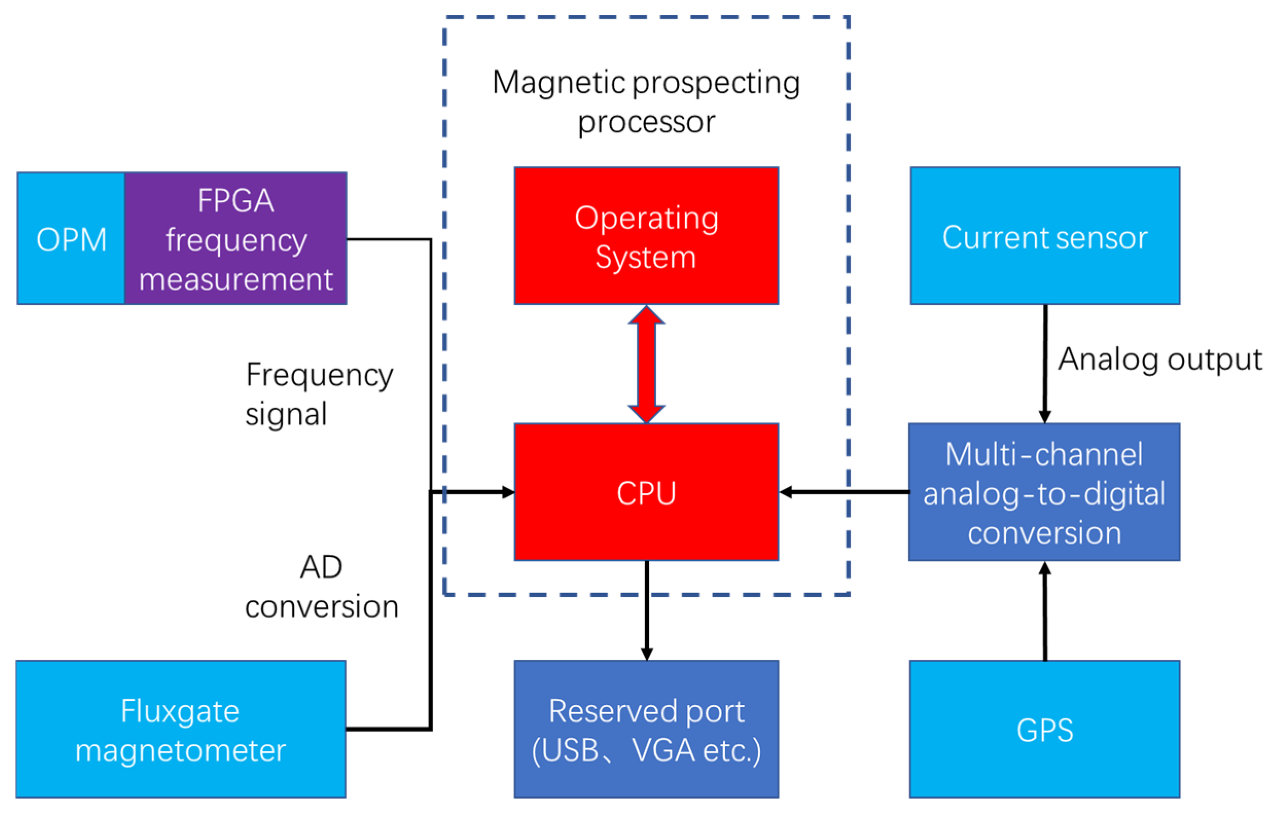
3.2.1. Experimental Equipment and Environment
3.2.2. Experimental Process
- (1)
- Install the UAV on the test bracket and place it in the north–south direction. Turn on the power supply but keep the engine off and the propeller still. All sensors start measuring synchronously;
- (2)
- Static test for 5 min to ensure that the experimental instruments are normal and there is no other magnetic interference in the environment;
- (3)
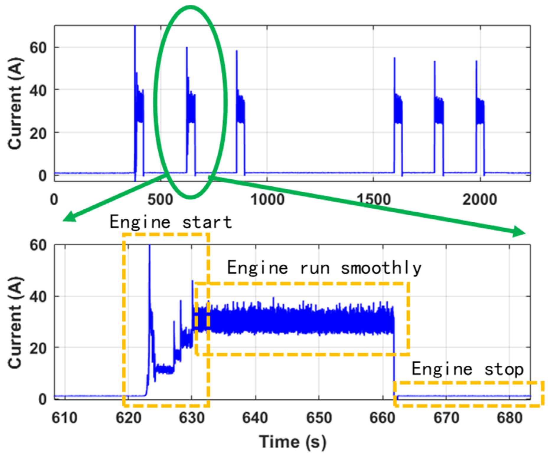
- Start the engine and keep the propeller turning for 30 s. Repeat 3 times, with an interval of 3 min each time;
- (4)
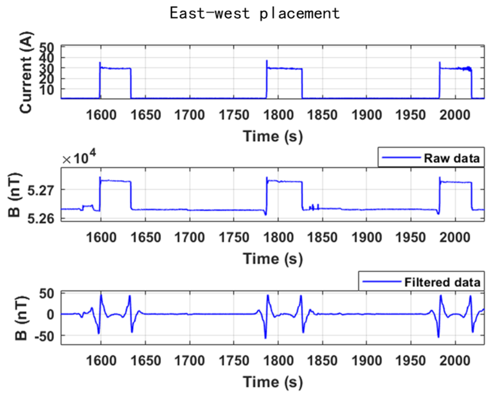
- Place the UAV in the east–west direction and repeat steps (2) and (3).
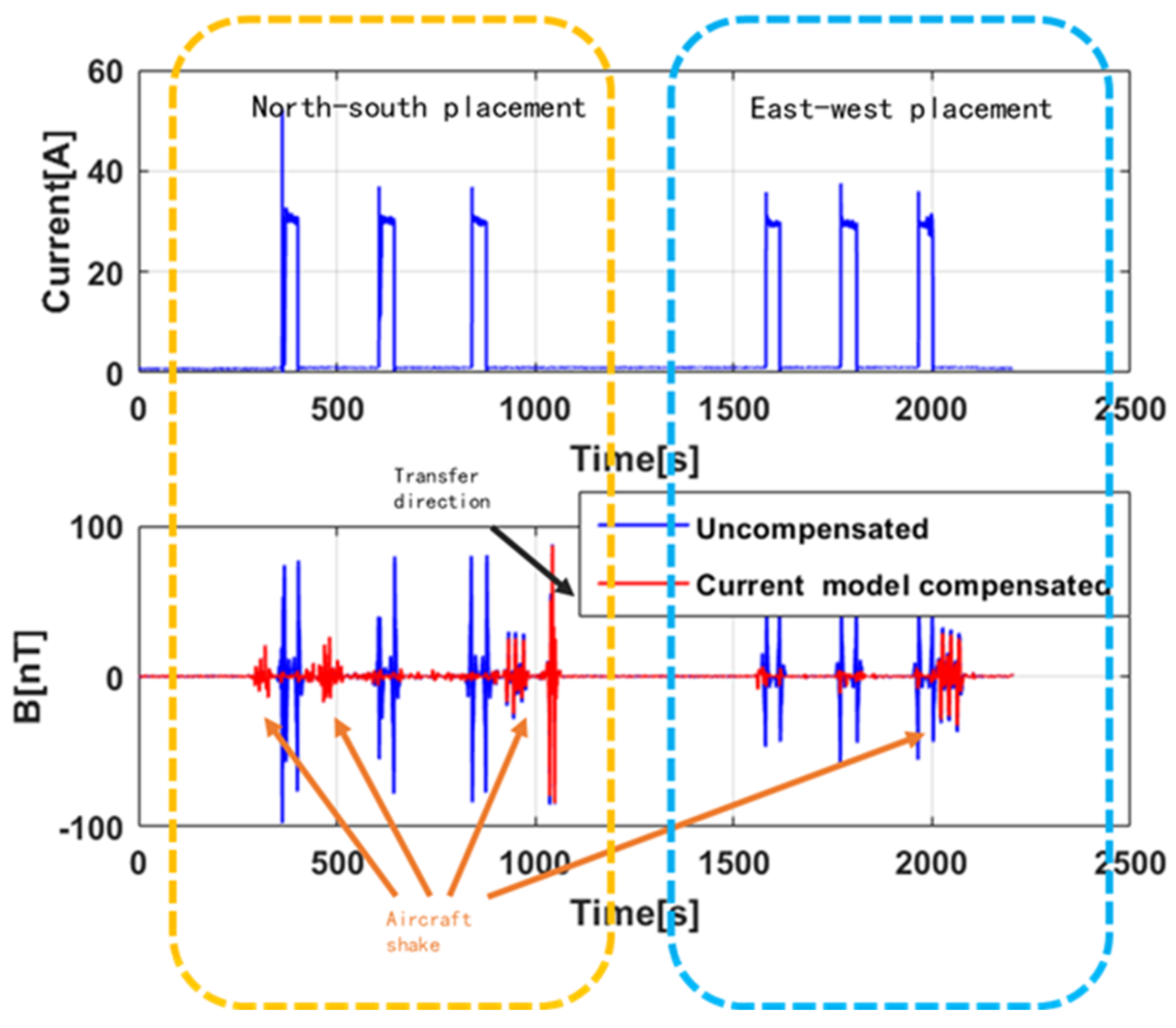
3.2.3. Experimental Results and Analysis
- (1)
- When the UAV engine is running, it brings large current to supply power and also produces great magnetic interference.
- (2)
- The magnetic interference of UAV airborne electronic equipment is mainly generated by power supply current. The magnetic interference vector of UAV electronic equipment should be similar to the characteristics of permanent magnet materials, regardless of the magnetic field’s magnetization.
- (3)
- The filtered waveform of the magnetic interference caused by the sudden change in current when the engine starts and stops is similar to the magnetic target signal. It causes serious interference to target recognition.
4. Proposed Method
4.1. Compensation Principle
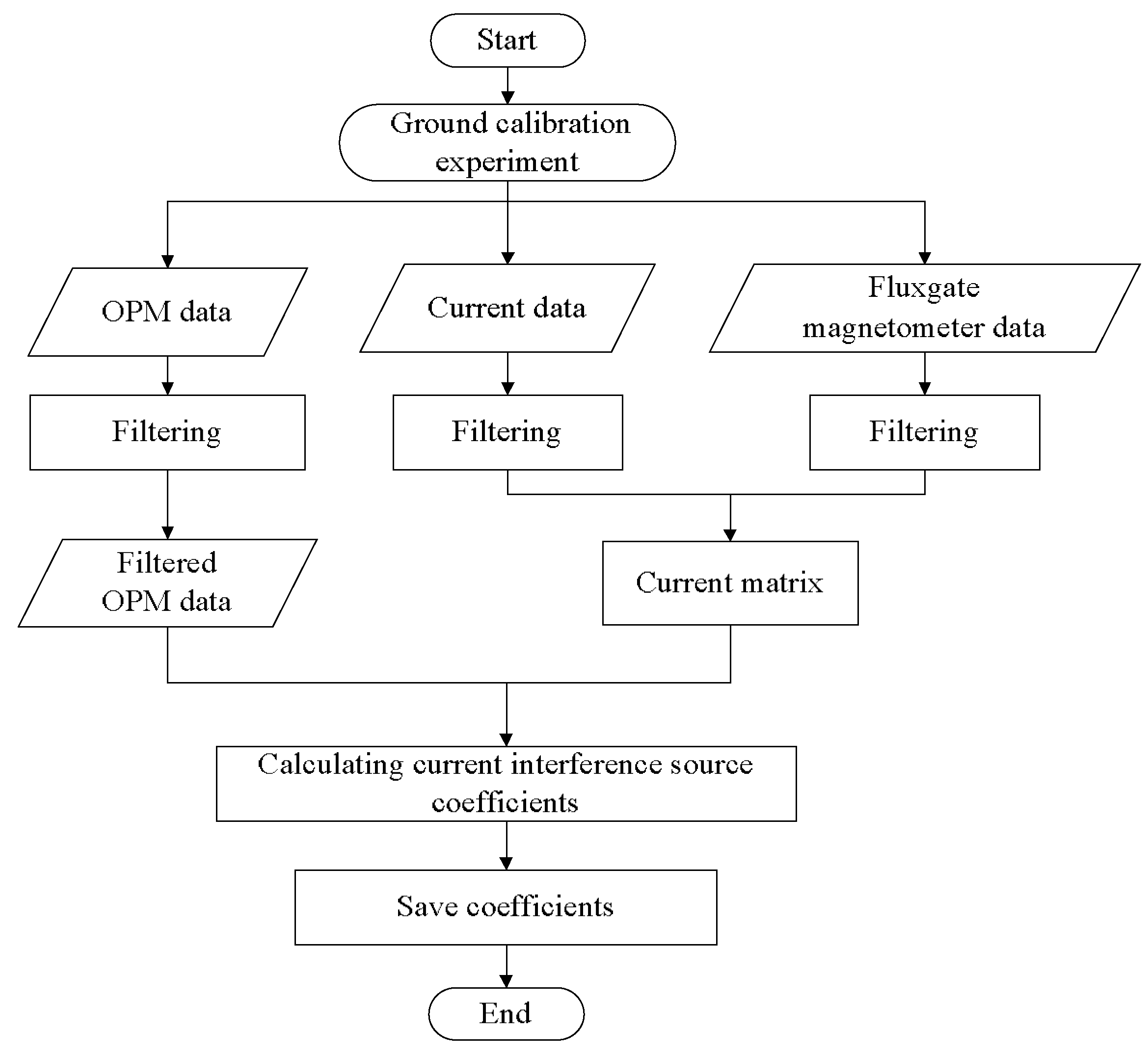
4.2. Calibration Process
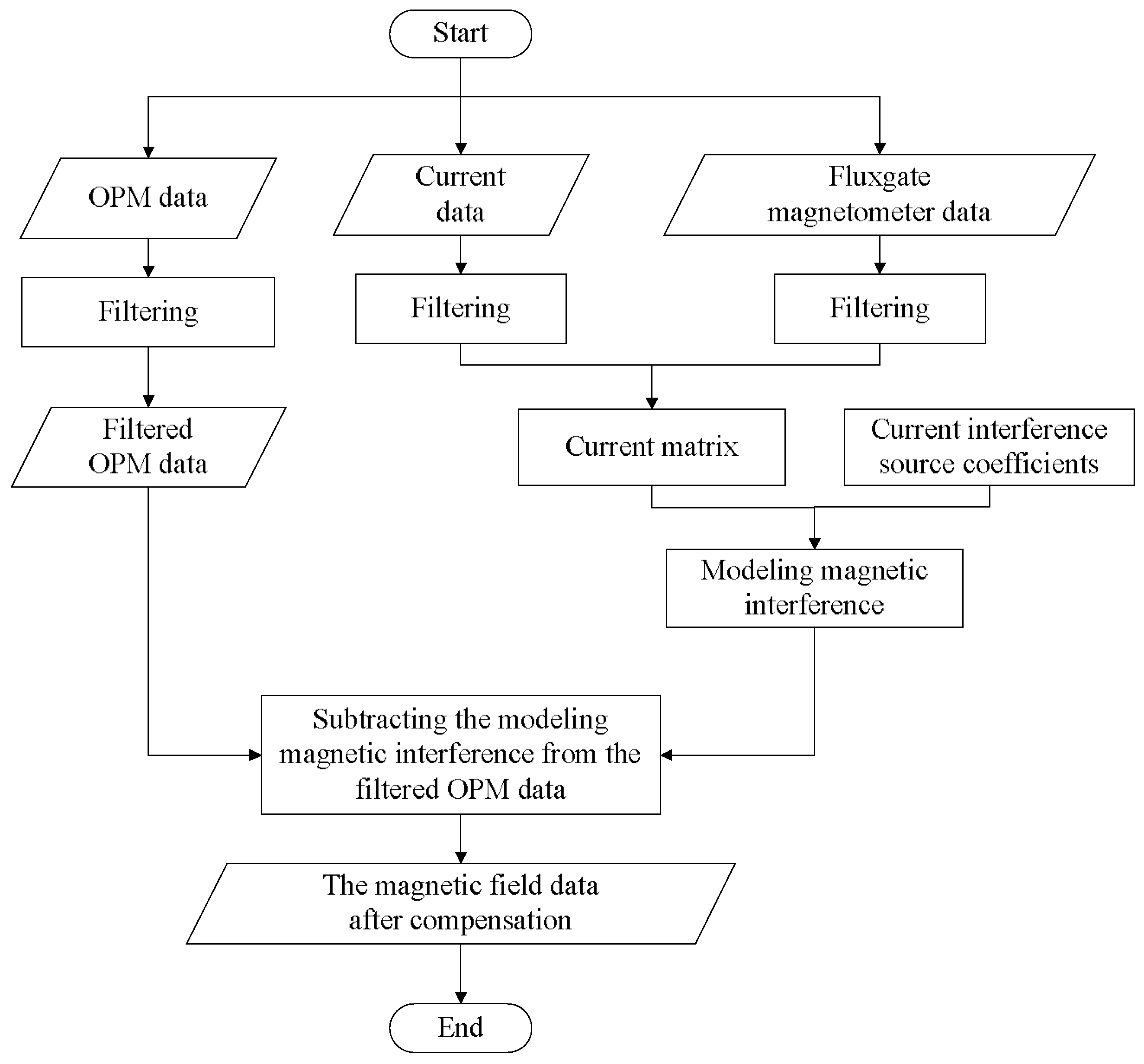
4.3. Data Processing Flow
- (1)
- Obtain the original magnetic data from the OPM and preprocess the magnetic data, mainly filtering.
- (2)
- Obtain original current data from a current sensor and combine the direction cosine information of the geomagnetic field from fluxgate magnetometer to construct the current matrix of the compensation model.
- (3)
- Calculate the compensation coefficients using the least square algorithm (LS).
- (4)
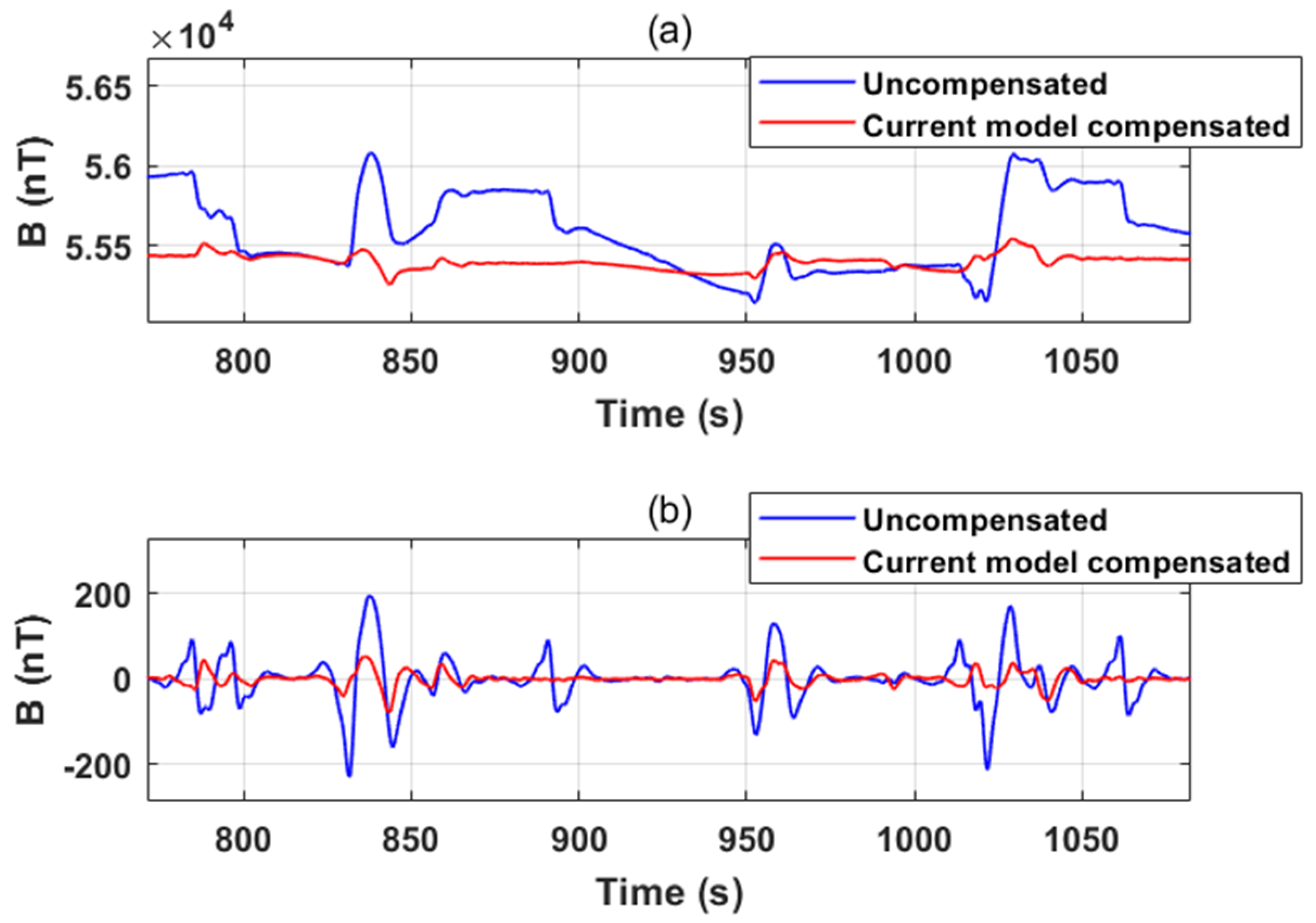
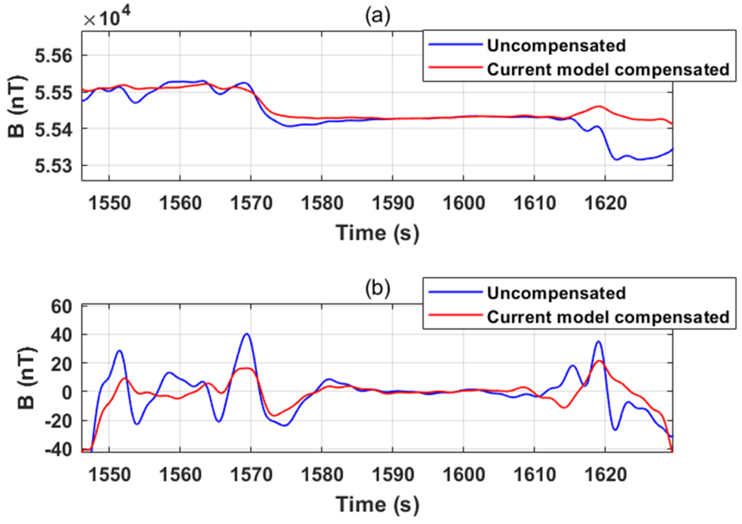
- The modeling interference is calculated using the current matrix and compensation coefficients, and the modeling interference is subtracted from the filtered OPM data to generate the magnetic field data after compensation.
4.4. Performance Metrics
5. Result
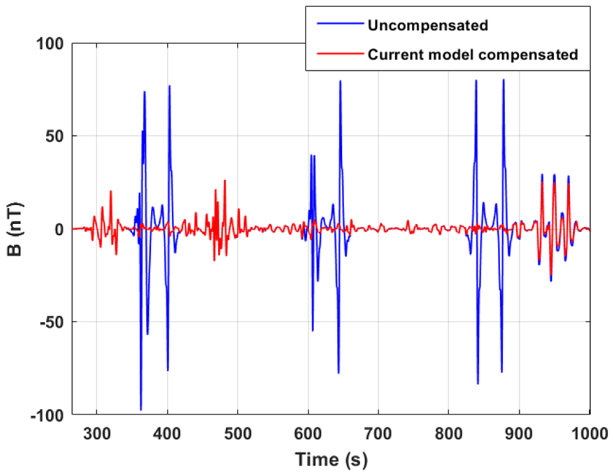
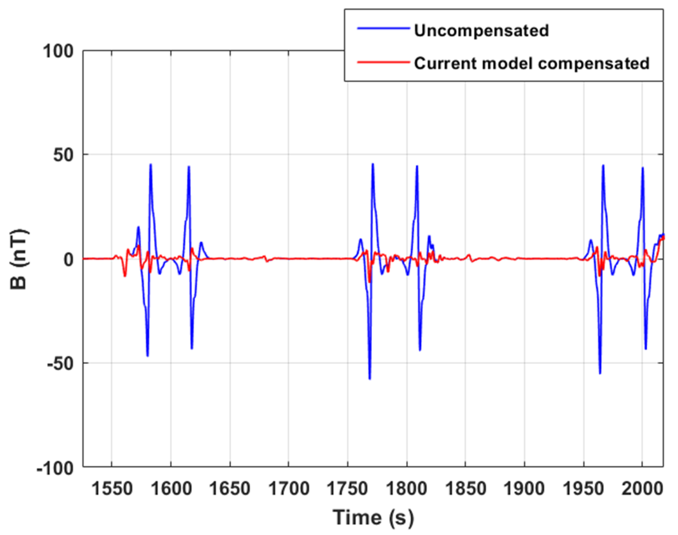
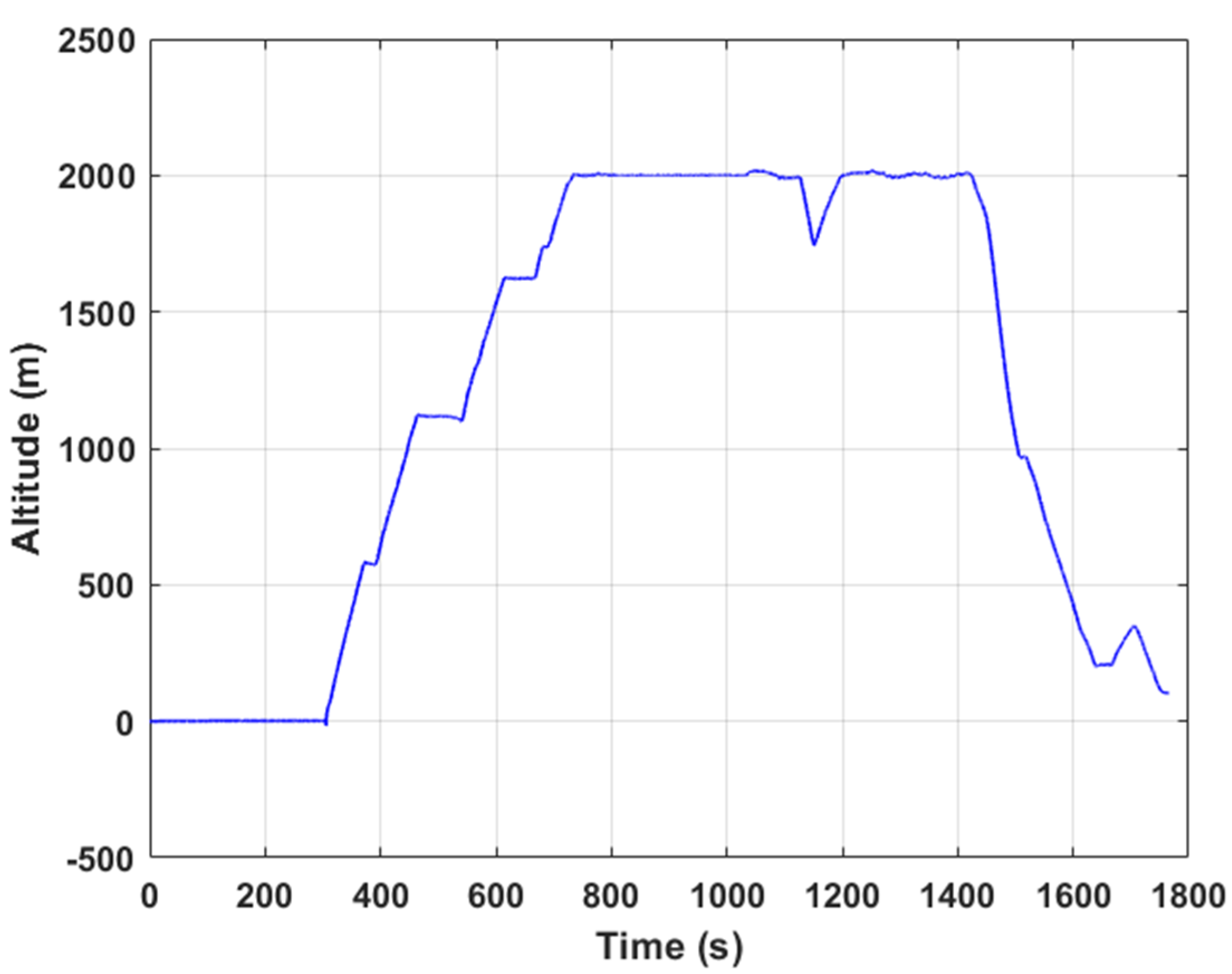
5.1. Experimental Result
5.2. Result Analysis
6. Conclusions
Author Contributions
Funding
Institutional Review Board Statement
Informed Consent Statement
Data Availability Statement
Acknowledgments
Conflicts of Interest
References
- Doll, W.E.; Gamey, T.J.; Bell, D.T.; Beard, L.P.; Sheehan, J.R.; Norton, J.; Holladay, J.S.; Lee, J.L.C. Historical Development and Performance of Airborne Magnetic and Electromagnetic Systems for Mapping and Detection of Unexploded Ordnance. J. Environ. Eng. Geophys. 2012, 17, 1–17. [Google Scholar] [CrossRef]
- Cunningham, M.; Samson, C.; Wood, A.; Cook, I. Aeromagnetic Surveying with a Rotary-Wing Unmanned Aircraft System: A Case Study from a Zinc Deposit in Nash Creek, New Brunswick, Canada. Pure Appl. Geophys. 2018, 175, 3145–3158. [Google Scholar] [CrossRef]
- Schmalzl, B.J. A UAV-Borne Magnetic Survey for Archaeological Prospection of a Celtic Burial Site. First Break 2020, 38, 61–66. [Google Scholar]
- Billings, S.; Wright, D. Interpretation of High-Resolution Low-Altitude Helicopter Magnetometer Surveys over Sites Contaminated with Unexploded Ordnance. J. Appl. Geophys. 2010, 72, 225–231. [Google Scholar] [CrossRef]
- Walter, C.; Braun, A.; Fotopoulos, G. High-resolution Unmanned Aerial Vehicle Aeromagnetic Surveys for Mineral Exploration Targets. Geophys. Prospect. 2020, 68, 334–349. [Google Scholar] [CrossRef]
- Krishna, V.; Silva, E.; Dssing, A. Experiments on Magnetic Interference for a Portable Airborne Magnetometry System Using a Hybrid Unmanned Aerial Vehicle (UAV). Geosci. Instrum. Methods Data Syst. 2021, 10, 25–34. [Google Scholar]
- Walter, C.; Braun, A.; Fotopoulos, G. Spectral Analysis of Magnetometer Swing in High-Resolution UAV-Borne Aeromagnetic Surveys. In Proceedings of the 2019 IEEE Systems and Technologies for Remote Sensing Applications through Unmanned Aerial Systems (STRATUS), Rochester, NY, USA, 25–27 February 2019. [Google Scholar]
- Zhang, X. Unmanned Aerial Vehicles for Magnetic Surveys: A Review on Platform Selection and Interference Suppression. Drones 2021, 5, 93. [Google Scholar] [CrossRef]
- Bickel, S.H. Small Signal Compensation of Magnetic Fields Resulting from Aircraft Maneuvers. IEEE Trans. Aerosp. Electron. Syst. 2007, 15, 518–525. [Google Scholar] [CrossRef]
- Zhiwen, C.; Dongsheng, C.; Fei, Y.; Haijuan, W.; Zhihui, Z. EMI Suppression of UAV Power in Aeromagnetic Survey. IEEE Electromagn. Compat. Mag. 2013, 2, 45–53. [Google Scholar] [CrossRef]
- Forrester, R.; Huq, M.S.; Ahmadi, M.; Straznicky, P. Magnetic Signature Attenuation of an Unmanned Aircraft System for Aeromagnetic Survey. IEEE/ASME Trans. Mechatron. 2014, 19, 1436–1446. [Google Scholar] [CrossRef]
- Noriega, G.; Marszalkowski, A. Adaptive Techniques and Other Recent Developments in Aeromagnetic Compensation. First Break 2017, 35, 31–38. [Google Scholar] [CrossRef]
- Abdelhamid, B.; Elkattan, M. Cancellation of Dynamic ON/OFF Effects in Airborne Magnetic Survey. Sens. Imaging 2017, 18, 26. [Google Scholar] [CrossRef]
- Du, C.; Wang, H.; Wang, H.; Xia, M.; Peng, X.; Han, Q.; Zou, P.; Guo, H. Extended Aeromagnetic Compensation Modelling Including Non-manoeuvring Interferences. IET Sci. Meas. Technol. 2019, 13, 1033–1039. [Google Scholar] [CrossRef]
- Walter, C.; Braun, A.; Fotopoulos, G. Characterizing Electromagnetic Interference Signals for Unmanned Aerial Vehicle Geophysical SurveysUAV Electromagnetic Interference. Geophys. J. Soc. Explor. Geophys. 2021, 86, J21–J32. [Google Scholar]
- Tuck, L.E.; Samson, C.; Laliberte, J.; Cunningham, M. Magnetic Interference Mapping of Four Types of Unmanned Aircraft Systems Intended for Aeromagnetic Surveying. Geosci. Instrum. Methods Data Syst. 2021, 10, 101–112. [Google Scholar] [CrossRef]
- Zheng, Y.; Li, S.; Xing, K.; Zhang, X. A Novel Noise Reduction Method of UAV Magnetic Survey Data Based on CEEMDAN, Permutation Entropy, Correlation Coefficient and Wavelet Threshold Denoising. Entropy 2021, 23, 1309. [Google Scholar] [CrossRef]
- Allred, J.C.; Lyman, R.N.; Kornack, T.W.; Romalis, M. V High-Sensitivity Atomic Magnetometer Unaffected by Spin-Exchange Relaxation. Phys. Rev. Lett. 2002, 89, 130801. [Google Scholar] [CrossRef] [PubMed] [Green Version]
- Tolles, W.E. Eddy-Current Compensation. U.S. Patent US55041544A, 13 August 1957. [Google Scholar]
- Tolles, W.E. Compensation of Aircraft Magnetic Fields. U.S. Patent 2692970A, 26 October 1954. [Google Scholar]
- Tolles, W.E. Magnetic Field Compensation System. U.S. Patent US2706801A, 19 April 1955. [Google Scholar]
- Zhang, D.; Liu, X.; Qu, X.; Zhu, W.; Huang, L.; Fang, G. Analysis of Aeromagnetic Swing Noise and Corresponding Compensation Method. IEEE Trans. Geosci. Remote Sens. 2022, 60, 1–10. [Google Scholar] [CrossRef]
- Tuck, L.; Samson, C.; Polowick, C.; Laliberte, J. Real-time Compensation of Magnetic Data Acquired by a Single-rotor Unmanned Aircraft System. Geophys. Prospect. 2019, 67, 1637–1651. [Google Scholar] [CrossRef]
- Erlichson, H. The Experiments of Biot and Savart Concerning the Force Exerted by a Current on a Magnetic Needle. Am. J. Phys. 1998, 66, 385. [Google Scholar] [CrossRef]
- Yan, B.; Zhu, W.; Zhuang, X.; Lu, Z.; Fang, G. Coil Optimization in a Fluxgate Magnetometer with Co68·2Fe4·3Si12·5B15 Amorphous Wire Cores for Geomagnetic Station Observation. IEEE Trans. Instrum. Meas. 2021, 70, 9510107. [Google Scholar] [CrossRef]
- Nelson, B. Aeromagnetic Noise from Magnetometers and Data Acquisition Systems. In Proceedings of the 8th International Congress of the Brazilian Geophysical Society, Rio de Janeiro, Brazil, 14–18 September 2003. [Google Scholar]
- Leach, B.W. Aeromagnetic compensation as a linear regression problem. In Information Linkage between Applied Mathematics and Industry; Academic Press: Cambridge, MA, USA, 1980; pp. 139–161. [Google Scholar]
- Noriega, G. Performance Measures in Aeromagnetic Compensation. Lead. Edge 2011, 30, 1122–1127. [Google Scholar] [CrossRef]
- Noriega, G. Model Stability and Robustness in Aeromagnetic Compensation. First Break 2013, 31, 73–79. [Google Scholar] [CrossRef]
- Hardwick, C.D. Important Design Considerations for Inboard Airborne Magnetic Gradiometers. Explor. Geophys. 1984, 49, 2004–2018. [Google Scholar] [CrossRef]


| Technical Index | Parameters | |
|---|---|---|
| Magnetic Sensor | Fluxgate Magnetometer | OPM-CAS-18-VL |
| Measuring range | ±100,000 nT | 10,000–105,000 nT |
| Noise level | 6 pT/sqrt Hz at 1 Hz | 0.3 pT/sqrt Hz at 1 Hz |
| Size | 32 × 32 × 152 mm | 53 × 78 mm |
| Weight | 160 g | 500 g |
| Orthogonality error | — — — — — — — — | |
| Resolution | 0.1 nT | 0.0001 nT |
| Maximum error | 10 nT | 2.5 nT |
| Current Sensor Parameters | Value |
|---|---|
| Measuring range | ±150 A |
| Accuracy at 100 A | ±0.45% |
| di/dt accurately followed | >200A/µs |
| Offset current | ±0.1 mA |
| Linearity | <0.15% |
| Size | 36.5 × 27.2 × 14.3 mm |
| Weight | 18 g |
| Parameters | Symbol | Value |
|---|---|---|
| Diameter of core | 100 μm | |
| Length of core | L | 20 mm |
| Wire diameter of excitation coil | 0.05 mm | |
| Turn number of excitation coil | 900 | |
| Wire diameter of pick-up coil | 0.08 mm | |
| Turn number of pick-up coil | 1045 | |
| Feedback resistance | 6 kΩ |
| Current Compensation Model Coefficients | Value | Current Compensation Model Coefficients | Value |
|---|---|---|---|
| c1 | −4.9112 | c4 | −3.8696 |
| c2 | −10.7720 | c5 | 5.3090 |
| c3 | −1.4785 | c6 | −5.0002 |
| Current Model Compensated | |
|---|---|
| Std before compensation (nT) | 15.5613 |
| Std after compensation (nT) | 1.5225 |
| IR | 10.2210 |
| Current Model Compensated | |
|---|---|
| P–p before compensation (nT) | 185.4457 |
| P–p after compensation (nT) | 12.5225 |
| Flight Experiment | Std before Compensation (nT) | Std after Compensation (nT) | IR |
|---|---|---|---|
| Climb | 64.2361 | 26.9110 | 2.3870 |
| Cruise | 53.3411 | 20.6491 | 2.5832 |
| Landing | 12.1922 | 6.0670 | 2.0096 |
Disclaimer/Publisher’s Note: The statements, opinions and data contained in all publications are solely those of the individual author(s) and contributor(s) and not of MDPI and/or the editor(s). MDPI and/or the editor(s) disclaim responsibility for any injury to people or property resulting from any ideas, methods, instructions or products referred to in the content. |
© 2023 by the authors. Licensee MDPI, Basel, Switzerland. This article is an open access article distributed under the terms and conditions of the Creative Commons Attribution (CC BY) license (https://creativecommons.org/licenses/by/4.0/).
Share and Cite
Chen, B.; Huang, L.; Zhang, K.; Hu, J.; Zhu, W. Magnetic Interference Analysis and Compensation Method of Airborne Electronic Equipment in an Unmanned Aerial Vehicle. Appl. Sci. 2023, 13, 7455. https://doi.org/10.3390/app13137455
Chen B, Huang L, Zhang K, Hu J, Zhu W. Magnetic Interference Analysis and Compensation Method of Airborne Electronic Equipment in an Unmanned Aerial Vehicle. Applied Sciences. 2023; 13(13):7455. https://doi.org/10.3390/app13137455
Chicago/Turabian StyleChen, Bingyang, Ling Huang, Ke Zhang, Jin Hu, and Wanhua Zhu. 2023. "Magnetic Interference Analysis and Compensation Method of Airborne Electronic Equipment in an Unmanned Aerial Vehicle" Applied Sciences 13, no. 13: 7455. https://doi.org/10.3390/app13137455
APA StyleChen, B., Huang, L., Zhang, K., Hu, J., & Zhu, W. (2023). Magnetic Interference Analysis and Compensation Method of Airborne Electronic Equipment in an Unmanned Aerial Vehicle. Applied Sciences, 13(13), 7455. https://doi.org/10.3390/app13137455