Article

Study of the Movement Dynamics of a Beet Leaves Harvester

by
Simone Pascuzzi
1,*,
Volodymyr Bulgakov
2,
Valerii Adamchuk
3,
Ivan Holovach
2,
Volodymyr Nadykto
4 and
Myroslav Budzanivskyi
3
1
Department of Soil, Plant and Food Science, University of Bari Aldo Moro, Via Amendola 165/A, 70126 Bari, Italy
2
Department of Mechanics, Faculty of Construction and Design, National, University of Life and Environmental Sciences of Ukraine, 15, Heroyiv Oborony Str., UA 03041 Kyiv, Ukraine
3
Institute of Mechanics and Automation of Agricultural Production of the National Academy of Agrarian Sciences of Ukraine, 11, Vokzalna Str., Glevakha stl, Vasylkivsky Dist., UA 08631 Kyiv, Ukraine
4
Department of Machine-Using in Agriculture, Dmytro Motornyi Tavria State Agrotechnological University, 18B, Khmelnytsky Ave., Zaporozhye Region, UA 72310 Melitopol, Ukraine
*
Author to whom correspondence should be addressed.
Appl. Sci. 2023, 13(2), 841; https://doi.org/10.3390/app13020841
Submission received: 13 December 2022 / Revised: 27 December 2022 / Accepted: 30 December 2022 / Published: 7 January 2023
(This article belongs to the Section Agricultural Science and Technology)

Abstract

:
High-quality cutting of beet heads during harvesting reduces the loss of sugar-bearing upper parts of root crops. One of the ways to ensure high quality cutting is to scientifically substantiate the parameters of the machine that harvests the sugar beet leaves; this machine is front-mounted on the tractor’s attachment mechanism. Theoretical calculations established the following. A front-mounted beet topper machine with damping coefficient and the moment of inertia parameters that vary from 0.35 to 1.35 kN s m−1 and from 3000 to 3500 kg m2, respectively, is invariant to the influence of external disturbances in the form of vertical vibrations of the field’s longitudinal profile. These vibrations vary in frequency from 0 to 40 s−1 according to the harmonic function. Setting the tyres stiffness coefficient value of the leaves harvester support-feeler wheels at 315 kN m−1 is characterized by a desirable decrease (up to 41.2%) of the dynamic system’s amplitude–frequency values characteristics when the system is subjected to an external disturbance. With this value of tyre stiffness coefficient, the tyre inflation pressure should not exceed 0.125 MPa.

1. Introduction

Recent research as well as technological and production tests show that sugar beet root tops, which were previously used primarily as an organic fertilizer, can be a raw material for biogas production [1,2]. Therefore, its harvesting and transportation is an important task in the field of agricultural mechanization [3,4]. In addition, high-quality cutting of the sugar beet root collar reduces the loss of sugar-bearing upper parts; this significantly increases the yield of beet raw material, and therefore the sugar yield, from each hectare of crops [5,6].
In recent years, the most widespread method of harvesting the beet heads in many beet-growing countries has been the multistage. During this stage, the entire mass of the leaves is cut and then harvested in a transport vehicle. Next, the beet root collars are cleaned or trimmed (or both are done simultaneously, using different tools) from the leaves’ remains [7,8].
These operations are carried out sequentially. Since leaves harvesting occurs before beet roots are pulled up, the topping tools must be front-mounted on a power vehicle (a tractor or front part of the composition). Topping tools can be independent agricultural machines or topper modules of a beet harvester [9].
However, experimental studies have established that the front-mounted leaves harvester makes oscillatory movements throughout the operative process in an area that is determined by: (i) the relief of the field surface; (ii) the tractor forward speed; (iii) the location of the feeler wheels relative to the machine’s suspension system; and so on. The suspension system of the beet leaves harvester causes oscillation of the machine in the vertical plane during the operative conditions. This affects the quality of the technological process itself, i.e., the uniform cutting and collection of the leaves from the collar of root crops along the entire working width of the machine without significant losses [10].
Despite the wide distribution and use of front-mounted beet leaves harvester modules, fundamental analytical studies of their oscillatory motion over irregular soil surfaces are practically absent. Bulgakov et al. [11] presented a theoretical study of a tractor-mounted beet harvester’s oscillations using the original Lagrange equations of the 2nd kind. However, this work does not consider all the forces acting on this dynamic system, so the obtained mathematical model of its motion does not adequately describe the real process. In addition, this problem considers a system that consists of two differential equations with respect to two generalized coordinates, even though the problem can be solved accurately enough using only one such coordinate.
Applying the same methodology as in [12], it is possible to build a more accurate mathematical model of the machine’s motion over an uneven ground surface. This makes it possible to study the influence of construction parameters on the considered motion along the rows of sugar beet roots.
The authors have developed a new universal machine that performs the technological process using the principle of a mower-shredder, which is front-mounted on a wheeled aggregating tractor. This machine uses a rotary cutting unit. The articulated cutting knives mounted on the drive drum have an arc shape; they rotate in the longitudinal-vertical plane and are supported by feeler wheels, providing cutting of the leaves’ main mass across the working width of the machine [13,14,15,16]. The green mass collected from the entire working width is loaded into the body of the nearby moving vehicle.
The harvesting efficiency of this type of leaves harvester is strongly affected by the motion stability of its rotor cutting unit in the longitudinal-vertical plane, the capability of its feeler to determine the unevenness of the soil surface in its working width, and the parameters of the tractor connection mechanism, among others [17]. This paper aims to study the dynamics of the front-mounted beet leaves harvester built by authors through an ad hoc mathematical model to assess the influence of the structural and kinematic parameters on the oscillations in the machine’s longitudinal-vertical plane during its technological process. Several factors create significant fluctuations in the considered dynamic system and degrade the quality of the technological process: the unevenness of the soil surface, which is traversed by the leaves harvester’s supporting wheels; the high speed of translational motion; and the presence of the pneumatic tyres that serve as guiding wheels. For the first time, we have built a universal mathematical model that links all these parameters with the dynamic characteristics of this system.

2. Materials and Methods

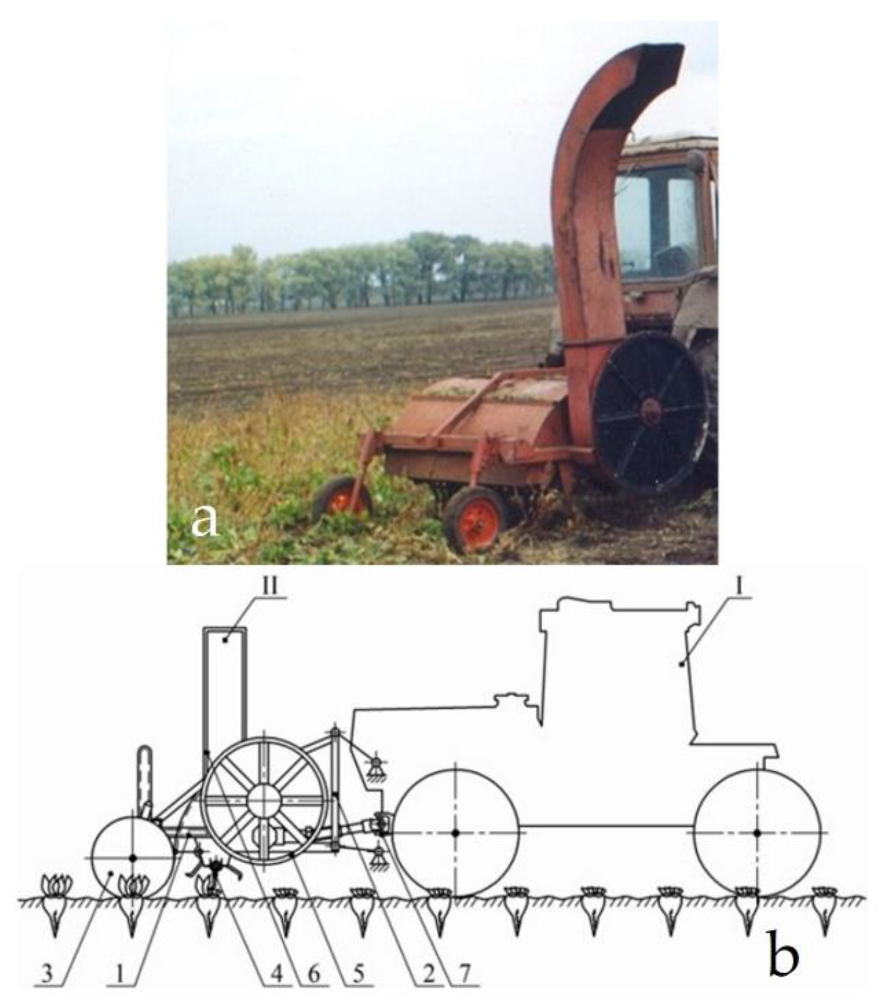
2.1. The Developed Front-Mounted Beet Leaves Harvester

Figure 1 shows the general view of the leaves harvesting machine conceived and built by the authors as well as its structural and technological scheme. The machine’s rotor makes a continuous cut and feeds the collected technological mass into the body of the accompanying vehicle; this includes bundles and leaves from the beet roots as well as plants that are present on the beet plantation during harvesting.
The technological process of harvesting sugar beet leaves is carried out in the following way. During the motion of the wheeled aggregating tractor I in the inter-rows of sugar beet root crops, the feeler wheels (3 in Figure 1) of the picker machine II, which are located in the front part of the frame (1 in Figure 1), set the rotor (4 in Figure 1) to the required cutting height. The rotor’s knives have an arc-shaped form and are installed on a cylindrical surface along the length of the rotor using hinges (4 in Figure 1) to ensure overlap on the entire working width of the machine. The knives rotate at a high frequency, ensuring excellent quality cutting of the entire crop mass. The absolute speed of arc knives blades reaches from 20 to 25 m s−1, and for mowing other thick-stemmed crops, from 40 to 50 m∙s−1 [16,18].
The leaves mass that is cut by the rotor’s arc-shaped knives (4 in Figure 1) moves to the upper part of the casing, where it falls on the screw conveyor. The conveyor moves the cut mass to the machine’s back section, where the transport device (5 in Figure 1) uses the chute (6 in Figure 1) to unload it into the vehicle’s body and then further on to the harvesting unit. The shaft that connects to the aggregating tractor I’s front power take-off drives the leaves harvesting machine (7 in Figure 1). The front-mounted leaves harvesting machine II is linked to aggregating tractor I by a three-point hitch device (2 in Figure 1). The final technological process of leaves harvesting takes place when the collars of the root crops are cleaned of leaf residues by a cleaner installed behind the tractor and equipped with a vertical drive shaft.
The article discusses the dynamics of motion for this front-mounted beet leaves harvester with roots that were sown in 0.45 m rows. The harvester was aggregated to an MTZ-82 tractor, and the rear wheels were equipped with 15.5R38 tyres. Since the width of the tyres’ profiles was 0.394 m, they fitted into the indicated row spacing of the beets. The wheel track of the specified tractor was then 1.8 m, allowing for 4 rows of beets placed between the wheels (4 × 0.45 = 1.8 m). With an even number of rows of the harvested crop placed between the tractor’s wheels, the system was symmetrically linked to the leaves harvester.

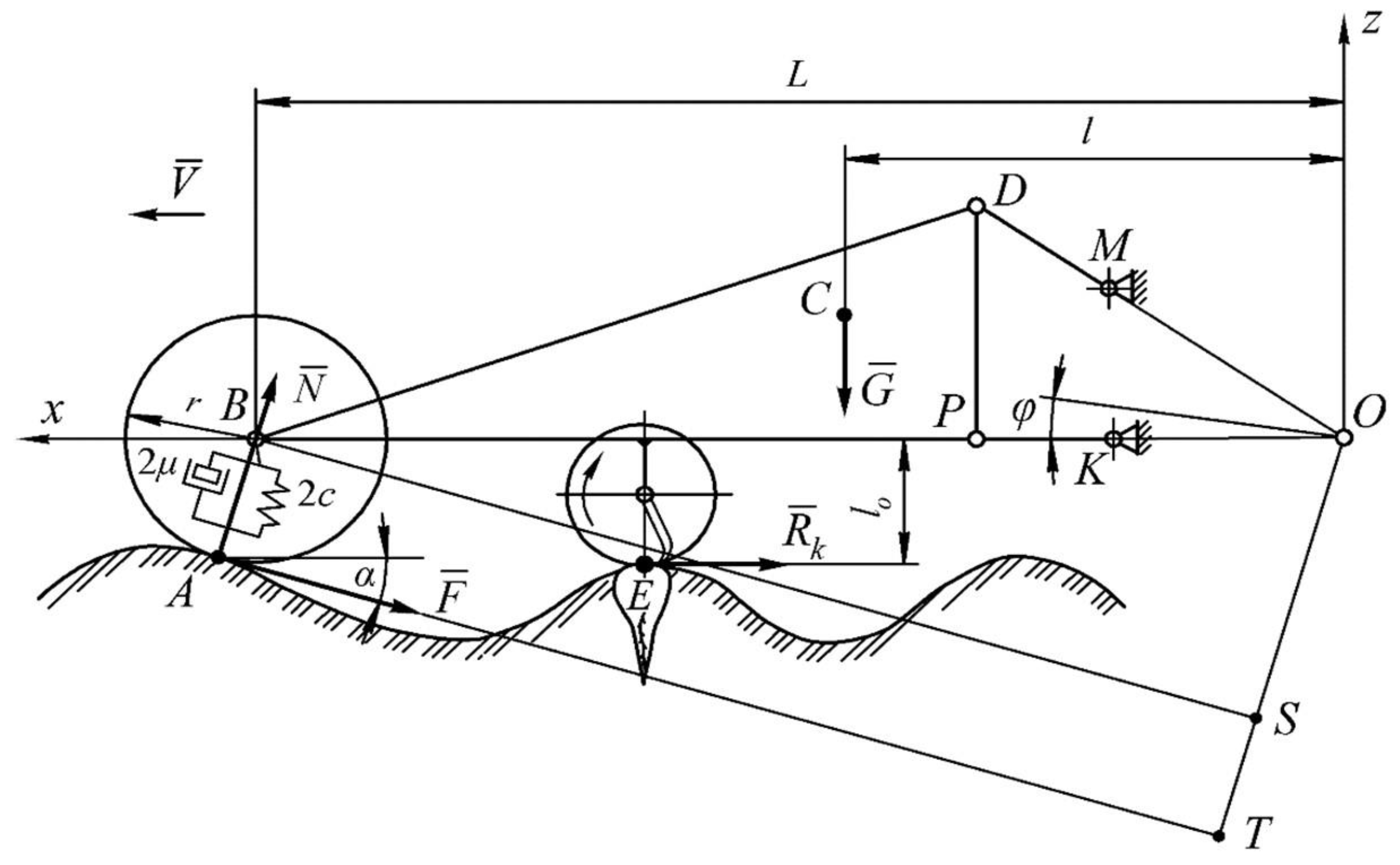
2.2. Theoretical Premises

To determine the influence of the structural and kinematic parameters of the front-mounted leaves harvesting machine on the oscillations in the longitudinal-vertical plane of the string cutting apparatus, it is necessary to build its mathematical model in the form of the corresponding differential equations. To do this, an equivalent scheme of this leaves harvesting unit was first drawn up (Figure 2).
As you can see from the diagram in Figure 2, the machine is connected to the tractor (not shown in the diagram) with the two lower (PK) and one upper (DM) connecting rods of its front linkage. During operation of this harvesting unit, the rods are in an unlocked position. This allows the front-mounted pick-up leaves harvester to feel the irregularities in the soil profile by means of its support wheels moving between the rows of sugar beet crops. Consequently, the support wheels act as feeler wheels, i.e., they ensure that the rotor cutter bar is positioned at the required height above the ground level.
The authors consider that both feeler wheels, even though they are in two different rows of sugar beet crops, move in the same ground conditions. Furthermore, the placement of the leaves unloading mechanism on the left side means that the leaves harvester has only one geometric nonlinearity. To balance the effect of the weight force of this mechanism, an appropriate ballast weight was installed on the right side of the machine. As a result, the leaves harvester’s left and right feeler wheels support the same vertical load. The irregularities of the agricultural soil surface can be represented in the form of the following harmonic function [19,20]:
h = h o · sin 2 π · x l 1 = h o · sin 2 π · V · t l 1 ,
where, regarding Figure 2:
  • h [m]: soil surface irregularity current ordinate.
  • h o [m]: amplitude of oscillations (step) of soil surface unevenness.
  • l 1 [m]: the period of oscillations (step) of soil surface i unevenness.
  • x = V · t [m]: the current abscissa of soil surface unevenness.
  • V [m s−1] is the forward speed of the leaves harvester.
Based on the assumed equality of motion conditions of both feeler wheels, we denote them in the equivalent scheme as one wheel and express it as one equivalent elastic-damping model, having total stiffness coefficients 2c and damping 2µ.
The harvester is influenced by the following external forces in the longitudinal-vertical plane:
  • the normal N ¯ and tangential F ¯ = f · N ¯ ground reactions, applied at the point of contact A of the feeler wheel with an uneven soil surface (f is the resistance factor of the feeler wheel rolling over the ground surface);
  • the weight G ¯ of the front-mounted pick-up leaves harvester applied in its centre of gravity;
  • the resistance reaction R ¯ k of the rotary cutter bar to cutting the leaves.
In the presence of irregularities in the longitudinal profile of the field, the harvester makes angular oscillations under the influence of these external forces relative to the “centre of instantaneous rotation” of the aggregating tractor’s attached mechanism, which is in the point O (Figure 2). The measure of this rotation is the angle φ, which is the only independent (generalized) coordinate of motion of the considered dynamic system, i.e., a frontally aggregated leaves harvesting machine.
The key technical parameters of the developed beet leaves harvester are reported in Table 1 [18].
The values of the coefficients c and μ have been taken from the reference books pertinent to the tyres (7.50R16) mounted on the wheels of the beet leaves harvester. The values of the linear parameters have been obtained by direct measurement on the prototype machine with an error of ±1 cm. In the mathematical model, these values have been conditionally taken as average, then increased or decreased by an acceptable value.
The inertia moment (Ioy) of the beet leaves harvester has been assessed based on a completely acceptable assumption that it is a rectangle near the longitudinal-vertical plane The mass M has been determined by weighing the prototype machine by means of a DPU-2 dynamometer (Lviv, Ukraine), having a measurement error of ±20 kg.

2.3. Mathematical Model

To obtain the law of change of the angle φ in analytical form, let us apply differential equations in the Lagrangian form of the second kind [21]:
d d t ( T φ ˙ ) T φ = Q φ P φ R φ ˙ ,
where:
  • T: kinetic energy of the considered dynamic system.
  • Q φ : generalized force.
  • P: potential energy of the system.
  • R: dissipative function (Rayleigh function).
  • φ : generalized coordinate.
  • φ ˙ : the generalized speed.
The kinetic energy T of the dynamic system under consideration is determined as follows [21,22,23]:
T = I o y · φ ˙ 2 2 ,
where I o y is the moment of inertia of the leaves machine relative to the axis Oy, perpendicular to the longitudinal-vertical plane zOx and passing through the point O, kg∙m2.
Using expression (3), we find that:
T φ = 0 ; d d t ( T φ ˙ ) = I o y · φ ¨ .
The potential energy of this dynamic system is formed by the work of the elastic forces of the supporting (feeler) wheels of the leaves harvester. In essence, this work is a function of the deflections of the wheels’ tyres. In analytical terms, the specified deflections can be represented by the difference between the amplitudes z of vertical oscillations of the wheels’ centres (point B in Figure 2) and the longitudinal profile of the field ( h ): i.e., ( z h ) .
Considering the above, the expression for calculating the potential energy of vibrations of the leaves harvester is as follows [24]:
P = 2 · c · ( z h ) 2 2 = c · ( z h ) 2 .
In the presence of the angle α (see Figure 2), the value of which can be considered small with sufficient accuracy for practice, the ordinate z is determined as follows:
z = ( L + r · sin α ) · φ = ( L + r · α ) · φ = L · φ + r · α · φ .
We emphasized above that the parameters α and φ are small quantities (α ≤ ≈12°; φ ≤ ≈10°). It is quite clear that their product will have an even smaller value, which, without any harm, can be neglected. Taking this into account, we obtain:
z = L · φ ; z ˙ = L · φ ˙ .
Taking Equations (7) into account, Equation (5) is as follows:
P = c · ( L · φ h ) 2 = c · ( L 2 · φ 2 2 · L · φ · h + h 2 ) .
The partial derivative of function (8) with respect to the parameter φ has the form:
P φ = 2 c · L 2 · φ 2 c · L · h .
The dissipative function R of the considered dynamic system is determined in a similar way [21,24]:
R = 2 · μ · ( z ˙ h ˙ ) 2 2 = μ · ( z ˙ h ˙ ) 2 .
Substituting Equations (7) into Equation (10), we finally obtain:
R = μ · ( L 2 · φ ˙ 2 2 · L · φ ˙ · h ˙ + h ˙ 2 ) .
The partial derivative of this function with respect to the parameter φ ˙ will be as follows:
R φ ˙ = 2 μ · L 2 · φ ˙ 2 μ · L · h ˙ .
Next, let us determine the generalized force Q φ considering the generalized coordinate φ . For this purpose, let us first determine the elementary work of active forces δ A φ (in this case these are the moments of forces) on a possible displacement δ φ . As a result, we have the following expression [21]:
δ A φ = N · B S · δ φ F · T O · δ φ R k · l o · δ φ G · l · δ φ ,
where BS, TO, l o , l are, respectively, the arms of the forces N ¯ , F ¯ , R k ¯ and G ¯ relative to the point O (Figure 2).
From Equation (13), we find that the generalized force Q φ equals:
Q φ = δ A φ δ φ = N · B S F · T O R k · l o G · l .
If the arms l o and l are constant during the motion of the harvester, the arms BS and TO are functions of the variable angle α (see Figure 2). The latter, in turn, is organically related to the function of vertical oscillations of the longitudinal field profile according to Equation (1). If we differentiate Equation (1) by the parameter x, we obtain:
d h d x = 2 π · h o l 1 · cos 2 π · V · t l 1 = tan α .
From Equation (15), according to the basic concepts of higher mathematics regarding the geometric essence of the derivative of a function [11], we have:
α = arctg ( 2 π · h o l 1 · cos 2 π · V · t l 1 ) .
The analysis of the scheme of Figure 2 shows that the arm B S = L · cos α . Considering the smallness of the angle α, according to which cos α 1 , we finally accept that B S = L .
The arm TO (Figure 2) is the sum of two segments: T O = T S + S O .
As T S = r , and S O = L · sin α = L · α , then finally we obtain:
T O = r + L · α .
Considering the above, Equation (14) is as follows:
Q φ = N · [ L f · ( r + L · α ) ] R k · l o G · l .
After substituting Equations (4), (9), (12) and (14) into the original Equation (2) and carrying out the corresponding transformations, we obtain the following differential equation for the rotations of the leaves harvesting machine in the longitudinal-vertical plane:
A 2 · φ ¨ + A 1 · φ ˙ + A 0 · φ = B 1 · h ˙ + B o · h + C ,
with the following positions:
A 2 = I o y ,
A 1 = 2 μ · L 2 ,
A 0 = 2 c · L 2
B 1 = 2 μ · L ,
B 0 = 2 c · L ,
C = N · [ L f · ( r + L · α ) ] R k · l o G · l = arctg ( 2 π · h o l 1 · cos 2 π · V · t l 1 )
For further analysis of the derived differential equation, we carry out the transition from a relatively complex differential form to a simple algebraic form of its representation. To do this, we apply the well-known differentiation operator S = d d t [25]. Considering this S operator, the differential Equation (19) has the following form:
( A 2 · s 2 + A 1 · s + A 0 ) · φ ( t ) = ( B 1 · s + B o ) · h ( t ) + C · 1 ( t ) ,
or
D 2 ( s ) φ ( t ) = D 1 ( s ) h ( t ) + C · 1 ( t ) .
Structurally, this equation, reflecting the behaviour of the studied dynamic system, has two input and one output variables. The output variable is the angle of rotation φ ( t ) of the frontal mower in the longitudinal-vertical plane relative to the point O (Figure 2). The internal nature of this initial parameter (i.e., the angle φ ) is formed by an operator of the following form:
D 2 ( s ) = A 2 · s 2 + A 1 · s + A 0
The first of the input variables is represented by vertical fluctuations of the longitudinal profile of the field h(t), which acts on the dynamic system through the transmission link described by the following operator:
D 1 ( s ) = B 1 · s + B 0
The second external influence is a unit step function 1(t) of the discrete change in each of the parameters of the coefficient C [see Equation (19)].
Since the resulting differential Equations (20) or (21) are linear, the superposition principle is valid with respect to them. According to this principle, the effect of input influences on the response of a dynamic system can be analysed separately. Taking this into account, first, let us consider the functioning process of the front-end leaves harvesting machine under the influence of fluctuations in the longitudinal profile of the track h ( t ) . In an analytical form, this process appears as follows [21]:
D 2 ( s ) φ ( t ) = D 1 ( s ) h ( t ) .
It is known [26] that the nature of the transformation of the input parameters for a particular dynamic system into the output is determined by the corresponding transfer function [W(s)]. For this case, it is as follows [21]:
W ( s ) = D 1 ( s ) D 2 ( s ) = B 1 · s + B o A 2 · s 2 + A 1 · s + A o .
The transfer function (25) is used to calculate the amplitude– and phase–frequency characteristics of the operation of the frontal picker under the influence of the vertical fluctuations of the field’s longitudinal profile. The algorithm for such a calculation is presented quite objectively in [21,27].
We emphasize that the input influence h(t) is inherently perturbative. The ideal amplitude–frequency characteristics of the dynamical system when it reproduces such influence should be equal to zero, and the phase–frequency characteristics should be directed to infinity [26]. This fact determines the vector of further theoretical research, which should have the following nature: parameters of the dynamic system under which its amplitude–frequency characteristics are as close as possible to zero and phase–frequency characteristics to infinity, and which are the most rational (that is, desirable).

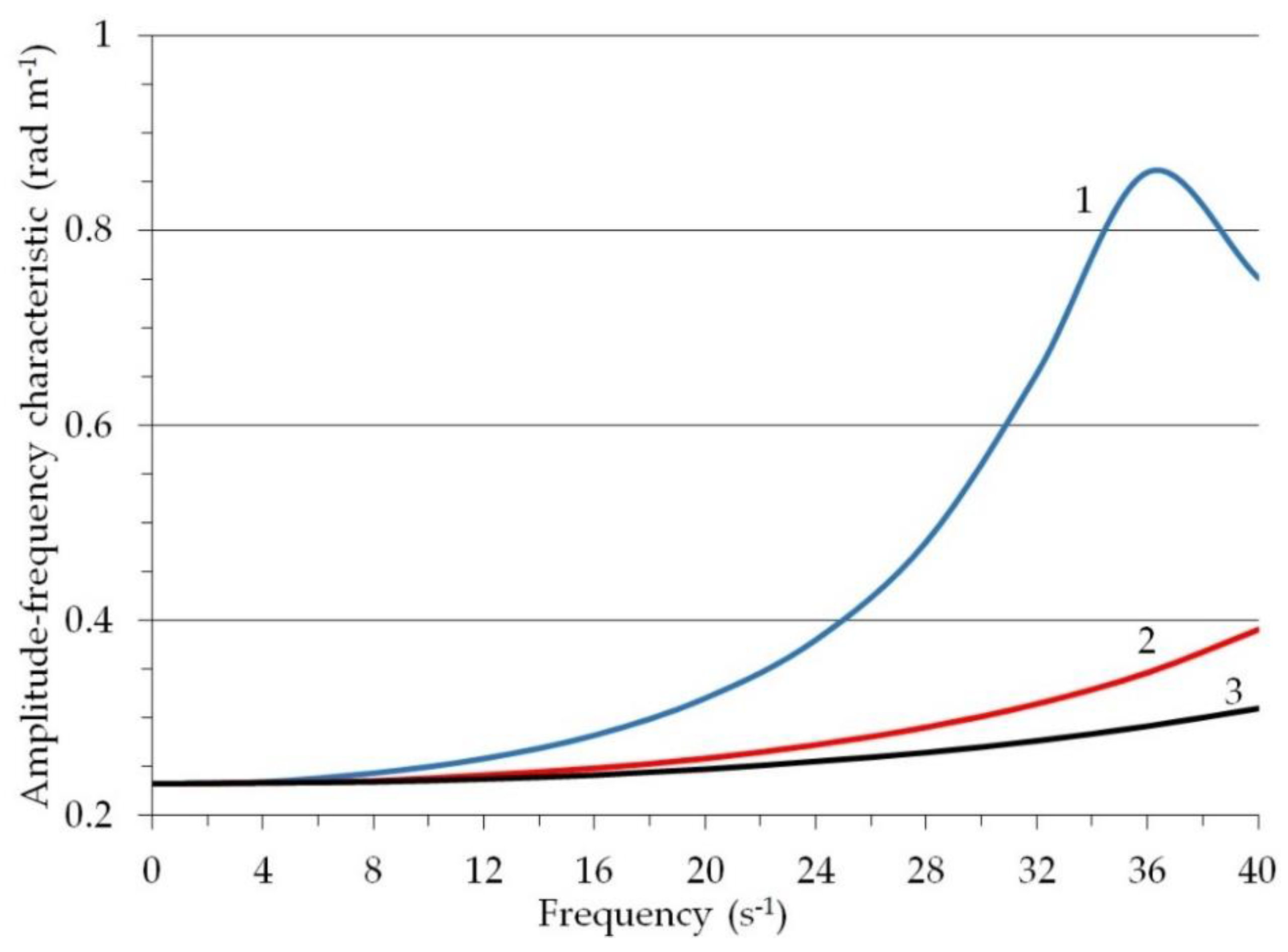
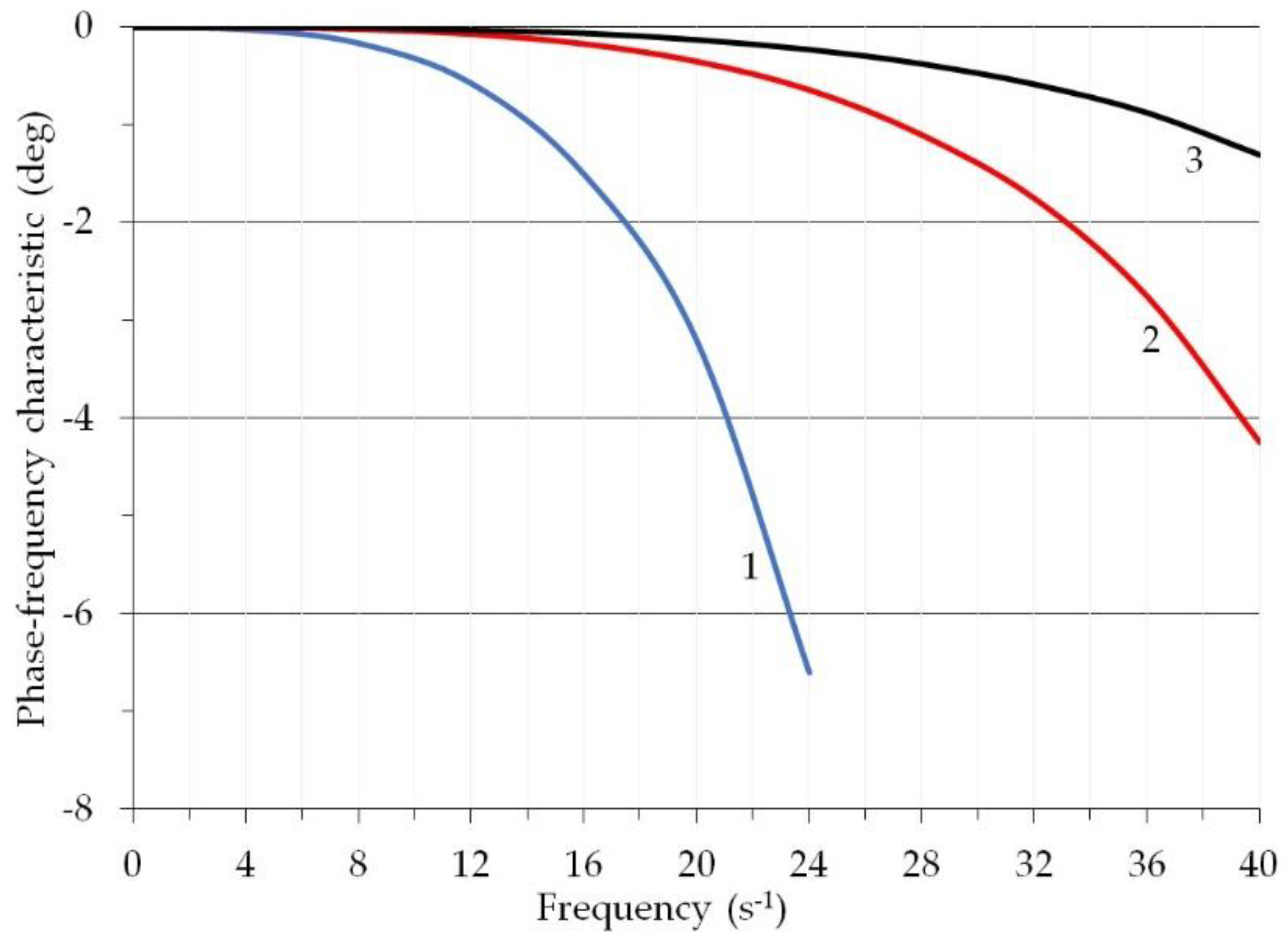
3. Results and Discussion

The values of coefficients A 2 , A 1 , A o , B 1 and B o of transfer function (25) are determined by the following construction parameters c , μ , L and I o y (see Equation (19)). In theoretical research we considered the following values: c in the range from 115 kN m−1 to 515 kN m−1; μ in the range from 0.35 kN s m−1 to 1.35 kN s m−1; L in the range from 3.8 m to 4.8 m; I o y in the range from 3000 to 3500 kg m2. These values have been conditionally taken based on the corresponding ones reported in Table 1, then increased or decreased by an acceptable value. Furthermore, for the simulation, we have considered the oscillations frequency range to be 0–40 s−1 as 40 s−1 was the highest value we located when examining long term (more than 10 years) measurements of fluctuations carried out in the longitudinal profile of fields with sugar beet roots.
It follows from the analysis of the calculation results that, at frequencies of external perturbation from 0 to 20 s−1 change in the parameters μ and I o y in the above ranges of their values do not practically affect the corresponding amplitude–frequency and phase–frequency characteristics of this dynamic system. In the frequency interval from 20 to 40 s−1, there is some qualitative difference between the corresponding frequency characteristics. However, the quantitative insignificance of this difference allows us to formulate the following conclusion: the front harvester with the values of parameters μ and I o y , which range from 0.35 to 1.35 kN s m−1 and from 3000 to 3500 kg m2, respectively, is invariant to the influence of external vertical vibrations of the agricultural background’s longitudinal profile, changing in the frequency range from 0 to 40 s−1 by the harmonic law (1).
On the other hand, the change in values of the stiffness coefficient ( c ) of the tyres of the harvester’s supporting and feeler wheels has a significant effect on the frequency characteristics of this dynamic system in the process of its response to the input disturbance. In the case where c = 115 kN m−1, we have the worst amplitude–frequency characteristic (curve 1 in Figure 3). Not only it is farthest from zero, but it also has an unwanted resonant peak at frequency 36 s−1.
Increasing the stiffness coefficient of tyres of the topper harvester’s support feeler wheels to 315 kN m−1 is characterized by a sharp enough desirable decrease in the amplitude–frequency characteristics of this dynamic system (curve 2 in Figure 3). At the frequency of 36 s−1, this decrease is 41.2%. This result is quite logical since the increase in the stiffness of the wheel tyres is accompanied by a simultaneous decrease in their elastic properties. The smaller the wheel tyres elastic properties, the lower the machine’s propensity to effects from its own vertical vibrations.
At a further increase of the coefficient c value by 200 kN m−1, the estimated amplitude–frequency response also decreases (curve 3 in Figure 3). At the same time, the intensity of this process significantly decreases. Taking this into account, it can be stated that there is no need to take the value of coefficient c of tyre stiffness of the leaves harvester feeler wheels higher than 315 kN m−1.
We consider how this can be used in practice. The tyre stiffness factor can be calculated by the following equation [28,29]:
c = 2 π ρ t · r c · r o ,
where:
  • ρ t [Pa] is the inflation pressure in the tyre.
  • r o [m] is the free radius of an unloaded tyre.
  • r c [m] is the radius of the tyre in its cross section.
The front harvester is equipped with feeler wheels that are fitted with 7.50R16, tyres, for which r o = 0.365 m, and r c = 0.440 m. Taking this into account, from Equation (26), we find that the inflation pressure in these tyres should be at the level of 0.125 MPa.
In contrast to the amplitude–frequency characteristics, the phase–frequency characteristics of the picker as a dynamic system deteriorate with an increase in the stiffness coefficient c of the tyres of its wheels. For proof, we consider the following results of mathematical modelling. Under the condition that c = 115 kN m−1, and the frequency of oscillations of external disturbance is 20 s−1, the considered phase–frequency characteristic of the dynamic system reaches a value of −3.2° or −0.06 rad. (curve 1 in Figure 4). In fact, these numerical values quantify the actual delay in the mower harvester’s response to the disturbing influence. At a disturbance frequency of 20 s−1 the delay is 0.06:20 = 0.003 s.
At the same time, when increasing the coefficient c up to 515 kN m−1 at the same frequency of oscillations of disturbing impact, the phase–frequency characteristic of this dynamic system decreases to the mark −0.1° or −0.002 rad (curve 3 in Figure 4). The delay of the harvester’s reaction to the perturbation drops to almost zero. It follows that for the desired increase in the phase shift when the dynamic system determines the disturbance in the form of vertical fluctuations of the agricultural background’s longitudinal profile, the value of the stiffness factor of the harvester’s tyres should be at the level of 115 kN m−1. Note that this conclusion is diametrically opposed to the amplitude–frequency characteristics considered above.
As a result, we should consider the fact that the character of the amplitude frequency response of the dynamic system to the disturbing action is more important, and therefore more determinative, than the phase factor. Taking this into account, to ensure the acceptable character of the harvester’s response to vertical fluctuations of the field’s longitudinal profile, the value of the coefficient c of its tyre feeler wheels’ stiffness should be at the level of 315 kN m−1.
As for such a construction parameter as L (see Figure 2), an increase in its value by 1 m (from 3.8 to 4.8 m) leads to the desired change in the amplitude–frequency characteristic of the studied dynamic system (Figure 5).
First, these frequency characteristics gradually decrease. This means that the dynamic system becomes less sensitive (that is, more resistant) to external disturbance. The logic of such a result is as follows. From the point of view of theoretical mechanics, the parameter L is nothing but the combined length of a physical pendulum, which is conventionally a picker machine. At the same time, it is known [30] that the larger the value of this length, the more stable the dynamic system is in the process of its functioning.
Secondly, the resonance peaks of the obtained amplitude–frequency characteristics are shifted towards higher frequencies of external disturbing oscillations. The higher the disturbance frequency, the smaller, as a rule, the dispersion of its oscillations [27], and, therefore, the amplitude of the angular oscillations of the picker.
Thirdly, under the condition that the value of the parameter L is equal to 4.8 m, the amplitude–frequency response of the dynamic system in the considered frequency range from 0 to 40 s−1 does not have an undesirable resonance peak at all (curve 3 in Figure 5).
The character of changes in the phase–frequency characteristics of the leaves harvester when increasing the value of the parameter L is diametrically opposite to the dynamics of the amplitude–frequency characteristics considered above. The greatest delay in the response of this dynamic system to an external disturbance occurs when L = 3.8 m, and the smallest when the value of L is the greatest and is 4.8 m (Figure 6).
At the same time, a significant difference between the obtained phase–frequency characteristics takes place at the frequencies of external perturbation oscillations greater than 25 s−1. As is known, this frequency interval [27] is characterized by sufficiently small values of the dispersion of the longitudinal field profile’s vertical oscillations. Taking this into account, we can state that the real effect of changing the construction parameter L has no significant influence on the value of the delay in the response of the frontal mower to the action of the external disturbance in the form of vertical oscillations of the field’s longitudinal profile.
The decisive moment when choosing the value of this parameter is the amplitude–frequency characteristics of the picker. According to the analysis, as emphasized above, it is desirable to set the value of L as large as possible. In practice, this can be achieved by attaching the harvester to the tractor in such a way that the angle between the connecting rods MD and DP (see Figure 2) is as large as possible. It should be kept in mind that the value of the DP parameter should in any case be greater than the value of the MK parameter, i.e., the shortest distance between the attachment points of the central and lower links of its front linkage to the tractor. When DP = MK, the DM and PK rods are parallel to each other. The front machine is therefore lifted into the transport position without turning it in the longitudinal-vertical plane, which is an undesirable result from the point of view of aggregating any machine/implement. The variant DP < MK is not acceptable at all as it makes lifting the front machine into the transport position impossible [31,32,33].

4. Conclusions

Theoretical studies have established that the front-mounted leaves harvester linked to a wheeled tractor is not affected by external perturbation or vibrations in the vertical plane if these change in frequency from 0 to 40 s−1 under the harmonic law (1), and if the values of parameters concerning the damping factor μ and moment of inertia Ioy of the harvester change from 0.35 to 1.35 kN s m−1 and from 3000 to 3500 kg m2, respectively.
The influence of the external perturbations can be controlled by setting the value of the coefficient c of the tyre stiffness of the harvester feeler wheels at 315 kN m−1. This value allows the desired reduction (to 41.2%) of values of the amplitude–frequency characteristics of the dynamic system to be obtained. At such a value of coefficient c of tyre stiffness, their inflation pressure should not exceed 0.125 MPa.
For a satisfactory trend of the amplitude–frequency characteristics of the harvester as a dynamic system under external perturbations, the value of the constructive parameter L, which is the distance from the axis of its feeler wheels to the instantaneous centre of rotation of the entire harvester, must be as large as possible. A limiting factor in this case is the connection of the leaves harvester to the tractor through the three point hitch attachment, which makes it impossible to arrange the central and lower connecting rods in parallel.
The new theory developed in this paper can be successfully used in the study and design of a large typology of agricultural implements connected to tractors, such as haulm harvesters, front-mounted mowers, front-mounted harvesters, front-mounted crop residue choppers, and so on. Using the method of mathematical modelling developed in this article, it is possible to design these machines with any number of rows and any kinematic, energy and design indicators. Ultimately, the developed theory makes it possible to carry out numerical simulation of oscillatory processes of many agricultural implements front-mounted to wheeled or tracked tractors.

Author Contributions

Conceptualization and Methodology, V.B., S.P. and V.A.; Formal Analysis, Investigation and Data Curation, S.P., V.A., I.H., V.N. and M.B.; Writing—Original Draft Preparation, V.B., S.P., I.H., V.N. and M.B.; Writing—Review & Editing, V.B., V.A., V.N. and M.B.; Supervision, V.B., S.P. and V.N. All authors have read and agreed to the published version of the manuscript.

Funding

This research received no external funding.

Institutional Review Board Statement

Not applicable.

Informed Consent Statement

Not applicable.

Data Availability Statement

Not applicable.

Conflicts of Interest

The authors declare no conflict of interest.

References

  1. Galvagno, A.; Chiodo, V.; Urbani, F.; Freni, F. Biogas as hydrogen source for fuel cell applications. Int. J. Hydrogen Energy 2013, 38, 3913–3920. [Google Scholar] [CrossRef]
  2. Theuerl, S.; Herrmann, C.; Heiermann, M.; Grundmann, P.; Landwehr, N.; Kreidenweis, U.; Prochnow, A. The Future Agricultural Biogas Plant in Germany: A Vision. Energies 2019, 12, 396. [Google Scholar] [CrossRef] [Green Version]
  3. Blanco, I.; Anifantis, A.S.; Pascuzzi, S.; Scarascia Mugnozza, G. Hydrogen and renewable energy sources integrated system for greenhouse heating. J. Agric. Eng. 2013, 44, 226–230.e45. [Google Scholar] [CrossRef]
  4. Pascuzzi, S.; Cerruto, E. An innovative pneumatic electrostatic sprayer useful for tendone vineyards. J. Agric. Eng. 2015, 46, 123–127. [Google Scholar] [CrossRef] [Green Version]
  5. Bulgakov, V. Sugar-Beet Harvesting Machines, 1st ed.; Agrarnaya Nauka: Kyiv, Ukraine, 2011; pp. 104–109. (In Russian) [Google Scholar]
  6. Guerrieri, A.S.; Anifantis, A.S.; Santoro, F.; Pascuzzi, S. Study of a Large Square Baler with Innovative Technological Systems that Optimize the Baling Effectiveness. Agriculture 2019, 9, 86. [Google Scholar] [CrossRef] [Green Version]
  7. Bell, B.; Rickatson, M. Farm Machinery, 6th ed.; 5m Publishing Ltd.: Sheffield, UK, 2015; pp. 217–223. [Google Scholar]
  8. Bulgakov, V.; Pascuzzi, S.; Holovach, I.; Olt, J.; Adamchuk, V.; Santoro, F. Theory of Vibrating Lifting Tools of Sugar Beet Harvesters, 1st ed.; MDPI: Basel, Switzerland, 2021; pp. 3–218. [Google Scholar] [CrossRef]
  9. Bzowska-Bakalarz, M.; Ostroga, K. The capacity of sugar beet farms‘ machinery and equipment. J. Cent. Eur. Agric. 2012, 13, 769–781. [Google Scholar] [CrossRef]
  10. Finkenstadt, V. A Review on the Complete Utilization of the Sugarbeet. Sugar Tech 2013, 16, 339–346. [Google Scholar] [CrossRef]
  11. Bulgakov, V.; Adamchuk, V.; Nozdrovicky, L.; Ihnatiev, Y. Theory of Vibrations of Sugar Beet Leaf Harvester Front-Mounted on Universal Traktor. Acta Technol. Agric. 2017, 20, 96–103. [Google Scholar]
  12. Vasilenko, P. Introduction to Agricultural Mechanics, 1st ed.; Agricultural Education: Kyiv, Ukraine, 1996; pp. 88–98. [Google Scholar]
  13. Bulgakov, V. Beet-Harvesting Machines, 1st ed.; Agrarian Science: Kyiv, Ukraine, 2011; p. 351. [Google Scholar]
  14. Pascuzzi, S.; Anifantis, A.S.; Santoro, F. The concept of a compact profile agricultural tractor suitable for use on specialised tree crops. Agriculture 2020, 10, 123. [Google Scholar] [CrossRef] [Green Version]
  15. Ihnatiev, Y. Theoretical research and development of new design of beet tops harvesting machinery. In Proceedings of the 5th International Science Congress “Agricultural machinery”, Varna, Bulgaria, 22–25 June 2017; Volume 1, pp. 46–48. [Google Scholar]
  16. Bulgakov, V.; Adamchuk, V.; Ivanovs, S.; Ihnatiev, Y. Theoretical investigation of aggregation of top removal machine frontally mounted on wheeled tractor. Eng. Rural. Dev. Jelgava 2017, 16, 273–280. [Google Scholar]
  17. Mawla, H.A.; Yehia, I.; El Lithy, A.M.; Faisal, A. An appropriate sugar-beet harvesting mechanization for big-scale project. MISR J. Agric. Eng. 2012, 29, 1213–1238. [Google Scholar] [CrossRef]
  18. Bulgakov, V.; Pascuzzi, S.; Ivanovs, S.; Santoro, F.; Anifantis, A.S.; Ihnatiev, I. Performance Assessment of Front-Mounted Beet Topper Machine for Biomass Harvesting. Energies 2020, 13, 3524. [Google Scholar] [CrossRef]
  19. Adamchuk, V.V.; Bulgakov, V.M.; Nadykto, V.T.; Kyurchev, V.M.; Ignatiev, E.I. Study of non-linearity of rows of soaked crops using a new indicator. Bull. Agrar. Sci. 2021, 8, 49–56. [Google Scholar]
  20. Bulgakov, V.; Pascuzzi, S.; Adamchuk, V.; Ivanovs, S.; Pylypaka, S. A theoretical study of the limit path of the movement of a layer of soil along the plough mouldboard. Soil Till. Res. 2019, 195, 104406. [Google Scholar] [CrossRef]
  21. Bulgakov, V.M.; Yaremenko, V.V.; Chernysh, O.M. Theoretical Mechanics, 1st ed.; Center for Educational Literature: Kyiv, Ukraine, 2019; p. 705. [Google Scholar]
  22. Zhou, L.; Moradi, Z.; Al-Tamimi, H.M.; Ali, H.E. On propagation of elastic waves in an embedded sigmoid functionally graded curved beam. Steel Compos. Struct. 2022, 44, 17–31. [Google Scholar] [CrossRef]
  23. Fang, Z.; Zhu, Z.; Wu, P.; Moradi, Z. Vibration and damping analysis of sandwich electrorheological fluid deep arches with bi-directional FGM containers. Eng. Struct. 2023, 276, 115325. [Google Scholar] [CrossRef]
  24. Bulgakov, V.; Pascuzzi, S.; Beloev, H.; Ivanovs, S. Theoretical Investigations of the Headland Turning Agility of a Trailed Asymmetric Implement-and-Tractor Aggregate. Agriculture 2019, 9, 224. [Google Scholar] [CrossRef] [Green Version]
  25. Bronstein, I.N.; Semendyaev, K.A. Handbook of Mathematics for Engineers and Students of Higher Educational Institutions, 1st ed.; Lan Publishing House: St. Petersburg, Russia, 2010; p. 608. [Google Scholar]
  26. Rotach, V.Y. Theory of Automatic Control, 1st ed.; MPEI Publishing House: Moscow, Russia, 2008; p. 396. [Google Scholar]
  27. Lurie, A.B. Statistical Dynamics of Agricultural Aggregates, 1st ed.; Kolos: Leningrad, Russia, 1980; p. 376. [Google Scholar]
  28. Guskov, V.V.; Velevm, N.N.; Atamanov, Y.E.; Bocharov, N.F.; Ksenevich, I.P.; Solonsky, A.S. Tractors. Theory, 1st ed.; Mashinostroenie: Moscow, Russia, 1988; p. 376. [Google Scholar]
  29. Bulgakov, V.; Pascuzzi, S.; Ivanovs, S.; Nadykto, V.; Nowak, J. Kinematic discrepancy between driving wheels evaluated for a modular traction device. Biosyst. Eng. 2020, 196, 88–96. [Google Scholar] [CrossRef]
  30. Gyachev, L.V. Sustainability of Movement of Agricultural Machines and Aggregates, 1st ed.; Mashinostroenie: Moscow, Russia, 1981; p. 206. [Google Scholar]
  31. Nadykto, V.T. Peculiarities of aggregating frontal guns. Agric. Mach. technol. 2011, 8, 8–11. [Google Scholar]
  32. Battiato, A.; Diserens, E. Influence of Tyre Inflation Pressure and Wheel Load on the Traction Performance of a 65 kW MFWD Tractor on a Cohesive Soil. J. Agric. Sci. 2013, 5, 197–215. [Google Scholar] [CrossRef]
  33. Prikner, P.; Kotek, M.; Jindra, P.; Pražan, R. Field compaction capacity of agricultural tyres. Agron. Res. 2017, 15, 806–816. [Google Scholar]
Figure 1. Front-mounted beet leaves harvester equipped with a rotary cutting unit linked to an aggregate tractor: (a), general view; (b), structural and technological scheme. I, wheeled rowing tractor; II, front-mounted beet leaves harvester: 1, frame; 2, connecting device; 3, feeler wheel; 4, rotary leaves cutting device; 5, transport device; 6, discharge chute; 7, drive shaft.
Applsci 13 00841 g001
Figure 2. Equivalent scheme of leaves harvesting machine attached to the front of the aggregating tractor.
Applsci 13 00841 g002
Figure 3. Amplitude–frequency characteristics of the dynamic system when examining the disturbance at different values of the tyre stiffness coefficient c of the tyre of the harvester’s feeler wheels: curve 1, c = 115 kN m−1; curve 2, c = 315 kN m−1;curve 3. c = 515 kN m−1.
Applsci 13 00841 g003
Figure 4. Phase–frequency characteristics of the dynamic system during the performance of the disturbance at different values of the tyre stiffness coefficient c of the tyre of harvester feeler wheels: curve 1, c = 115 kN m−1;curve 2, c = 315 kN m−1; curve 3, c = 515 kN m−1.
Applsci 13 00841 g004
Figure 5. Amplitude–frequency characteristics of the dynamic system during the performance of the disturbance at different values of the parameter L : curve 1, L = 3.8 m; curve 2, L = 4.3 m; curve 3, L = 4.8 m.
Applsci 13 00841 g005
Figure 6. Phase–frequency characteristics of the dynamic system during the performance of the disturbance at different values of the parameter L : curve 1, L = 3.8 m; curve 2, L = 4.3 m; curve 3, L = 4.8 m.
Applsci 13 00841 g006
Table 1. Main technical parameters of the front-mounted beet leaves harvester.
IndexUnitValue
Machine weight with haulm ( G )N9300
Operating forward speed ( V )m·s−12.2–2.5
Performanceha·h−11.08–1.35
Beet leaves harvester inertia moment (Ioy)kg·m23250
Tyres for support feeler wheels-7.50R16
Radius for support feeler wheelsm0.365
Inflation pressure of the support feeler wheels tyresMPa0.125
Stiffness coefficient (c) of the support feeler wheels tyreskN·m−1315
Damping coefficient (μ) of the support feeler wheels tyreskN·s·m−10.85
Rotor radius of the leaves cutterm0.30
Distance from the machine suspension axis to the axis of the support feeler wheels (L)m4.3
Distance from the machine suspension axis to the centre of gravity (L-l)m3.0
Soil profile fluctuation amplitude (h0)m0.01–0.03
Soil profile unevenness step ( l 1 )m0.70
Disclaimer/Publisher’s Note: The statements, opinions and data contained in all publications are solely those of the individual author(s) and contributor(s) and not of MDPI and/or the editor(s). MDPI and/or the editor(s) disclaim responsibility for any injury to people or property resulting from any ideas, methods, instructions or products referred to in the content.

