To validate the anti-slide short pile calculation method proposed in this paper, we conducted model tests on anti-slide short piles. These tests involved analyzing and organizing experimental data and then comparing the obtained results with calculations based on the method developed in this paper. This process ensures the effectiveness of the calculation method in practical engineering applications.
3.1. Experimental Design
This paper conducts a similarity design for the model test, building on design insights from previous anti-slide pile model tests [
39]. The cross-sectional dimensions of the full-scale anti-slide pile in the practical project are 1.0 × 1.6 m², constructed of concrete. Using similarity theory and the deflection equation for anti-slide piles, the corresponding conditions for the model test are determined as follows:
To establish a comparison between the model pile and the pile used in the practical engineering, the following equation must be met:
Following similarity theory, the calculation for reinforcing the short pile used in the test is conducted. The bending moment similarity constant is determined as follows:
Reinforcement configuration with equivalent cross-sectional area:
Shear force similarity coefficient:
Equivalent cross-sectional area for the tie reinforcement configuration:
In the equation, the variables represent the following: Aps: cross-sectional area of the prototype reinforcement; Apc: design compressive strength of concrete in the prototype structure; fpy: design tensile strength of steel reinforcement in the prototype structure; Ams: cross-sectional area of the reinforcement in the model structure; Amc: cross-sectional area of gypsum in the model structure; fmc: design compressive strength of gypsum in the model structure; fmy: design tensile strength of aluminum bars in the model structure.
In this model test, when
fy =
fy’ =
fmy = 100 N/mm
2,
M = 607.61 N·m,
b = 50 mm,
h0 = 69 mm,
α1 = 1.0,
ξb = 0.6,
fc =
fmc = 7.3 N/mm
2 by means of Equation (26):
αs = 0.348, by means of Equation (27):
ξ = 0.4488, by means of Equation (28):
γs = 0.776, plug into Equation (29):
determined that
As = 109.43 mm². Following the principles of similarity theory and the deflection equation for anti-slip short piles, we selected five
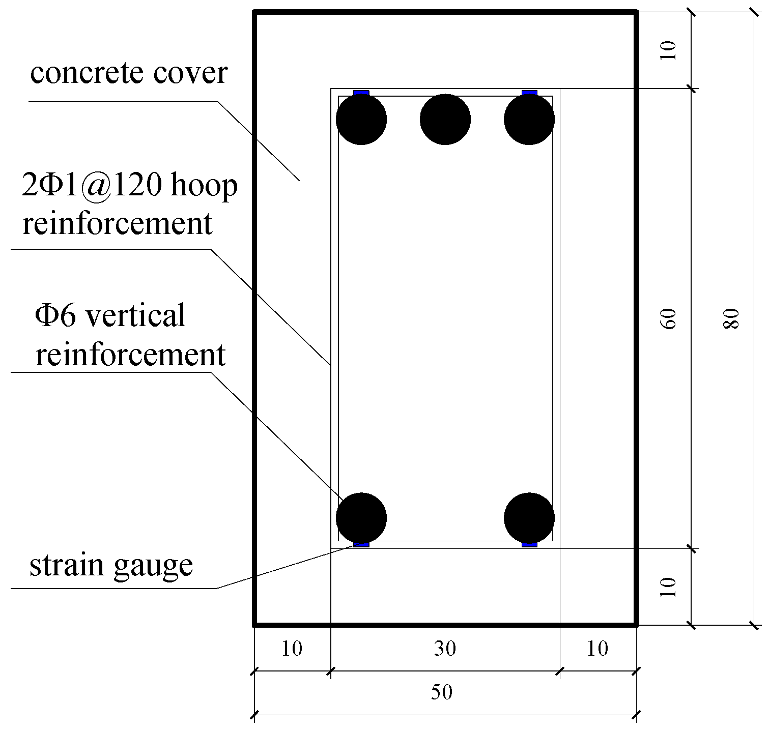
Φ6 aluminum bars for longitudinal reinforcement in the model test, while maintaining a protective layer thickness of 10 mm. The tie reinforcement comprised two
Φ1 helical wires with a 125 mm spacing. Based on the calculated reinforcement for the anti-slip short pile, we completed the arrangement of the aluminum bar cage.
Figure 4 depicts the reinforcement configuration for the anti-slip pile, ensuring compliance with the similarity conditions for the model test.
Following the principles of similarity theory and the deflection equation for anti-slip piles, the model test attained similarity conditions with a fundamental geometric similarity ratio
C1 = 20 and a fundamental stress similarity ratio
C0 = 20. The precise similarity relationships are detailed in
Table 1.
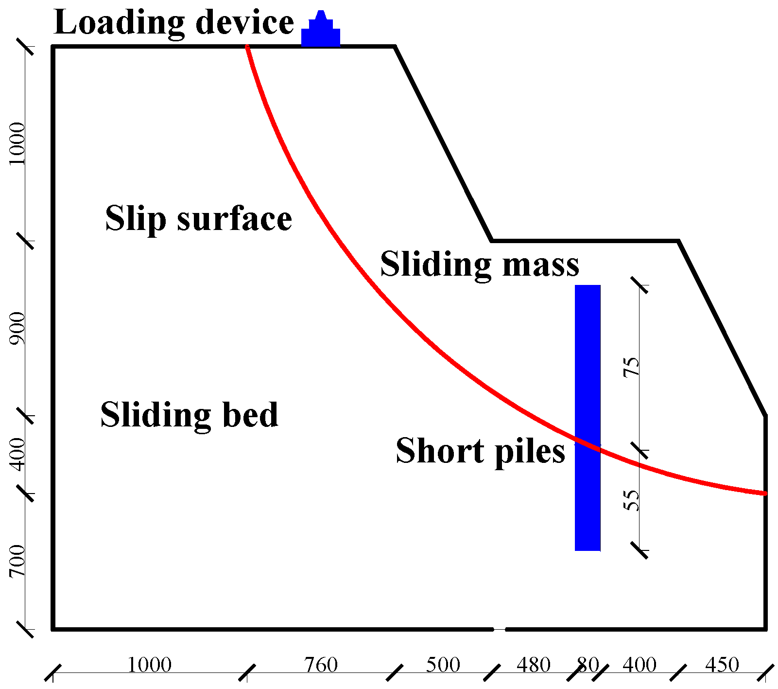
After establishing the fundamental physical properties of the landslide soil material utilized in the model test, the material for the anti-slip pile model was selected based on the provided table. Ultimately, high-strength gypsum was chosen to mimic actual concrete material, and aluminum bars were employed to replicate actual steel reinforcement. Given a geometric similarity constant of 20, the model pile had cross-sectional dimensions of 50 × 80 mm². In line with the geometric similarity ratio, the anti-slip pile was constructed as a cast-in-situ concrete pile measuring 1300 mm in length, with an embedded section of 550 mm, as depicted in
Figure 5 and
Figure 6.
For the experiment, the sliding bed and sliding mass materials were sourced from the homogenous loess found in the northern suburbs of Xi’an, representing the prototype soil. The loess was saturated with water to attain its optimal moisture content, layered, and compacted to establish a specific bearing capacity [
40]. The fundamental physical properties of the soil, as detailed in
Table 2, were determined through geotechnical testing.
The material for the anti-slip pile was composed of high-strength gypsum, cement, and water in a ratio of 10:7:2. Test specimens were prepared and cured under standard conditions, resulting in a uniaxial compressive strength of 15 GPa. To closely replicate the prototype, reinforcement was integrated into the anti-slip pile. The steel cage was constructed using aluminum bars to represent longitudinal reinforcement, with a 6 mm diameter. Three longitudinal bars were placed on the backside of the pile and two on the front side. Fine iron wires were used for tie reinforcement, with a 1 mm diameter, spaced at 10 cm intervals. The anti-slip pile was cast in pre-prepared molds made of hard wood panels. Following casting, it was cured for 30 days in appropriate environmental conditions.
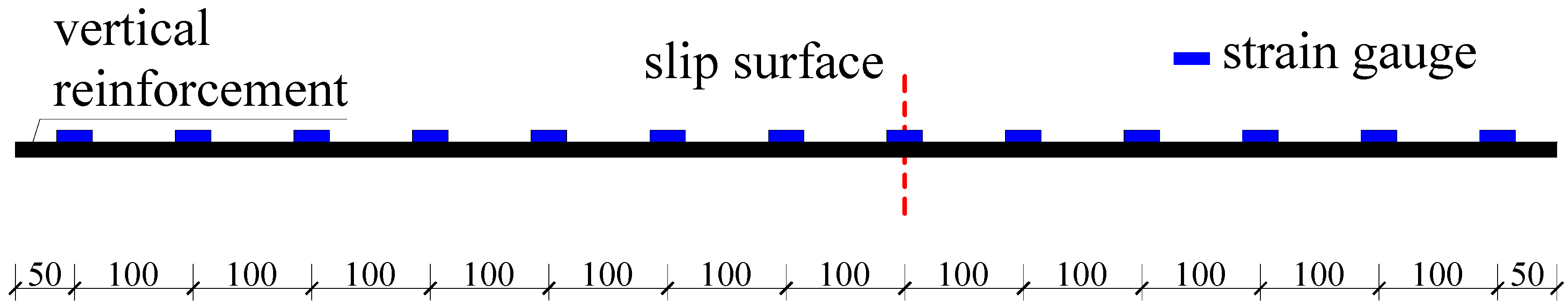
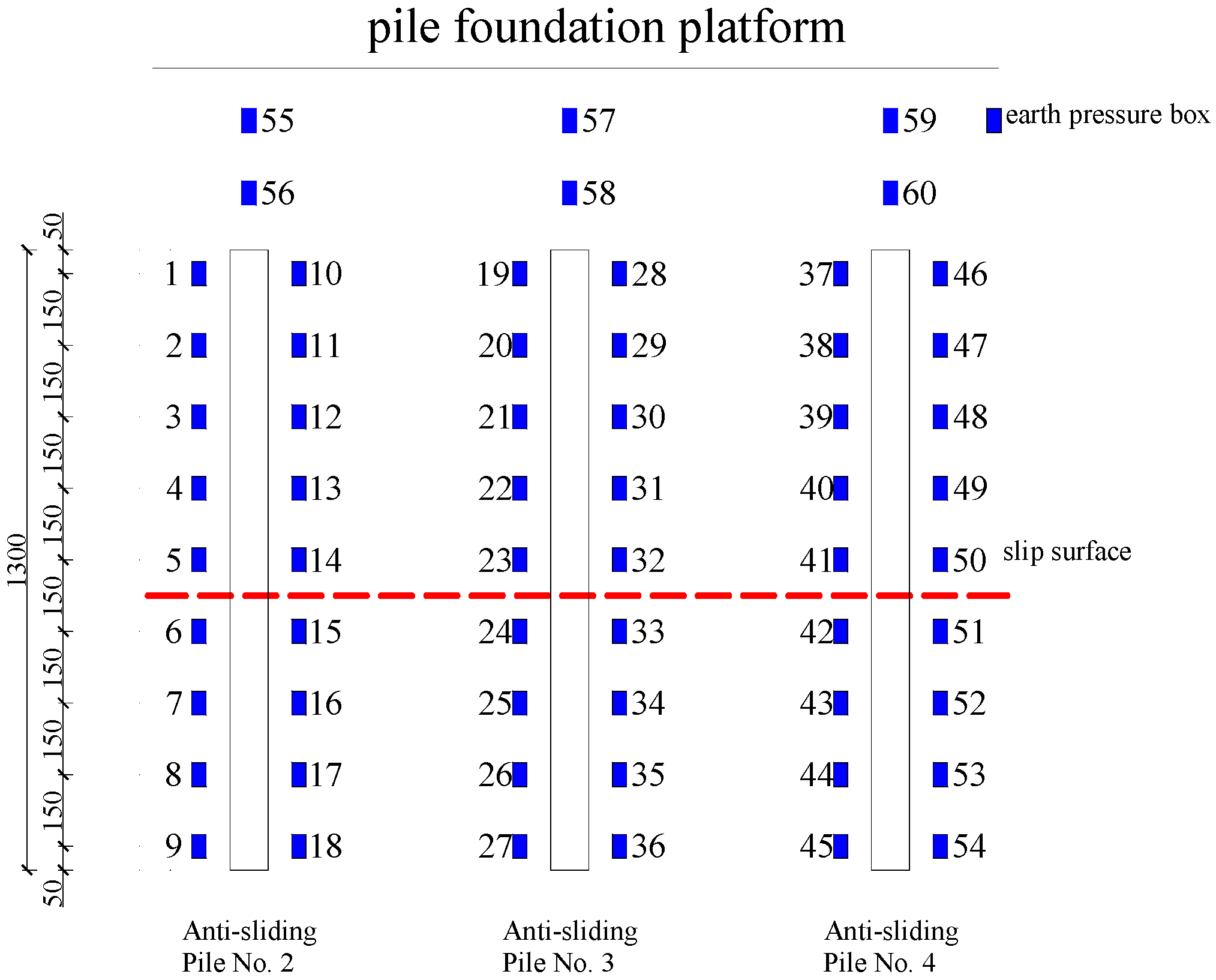
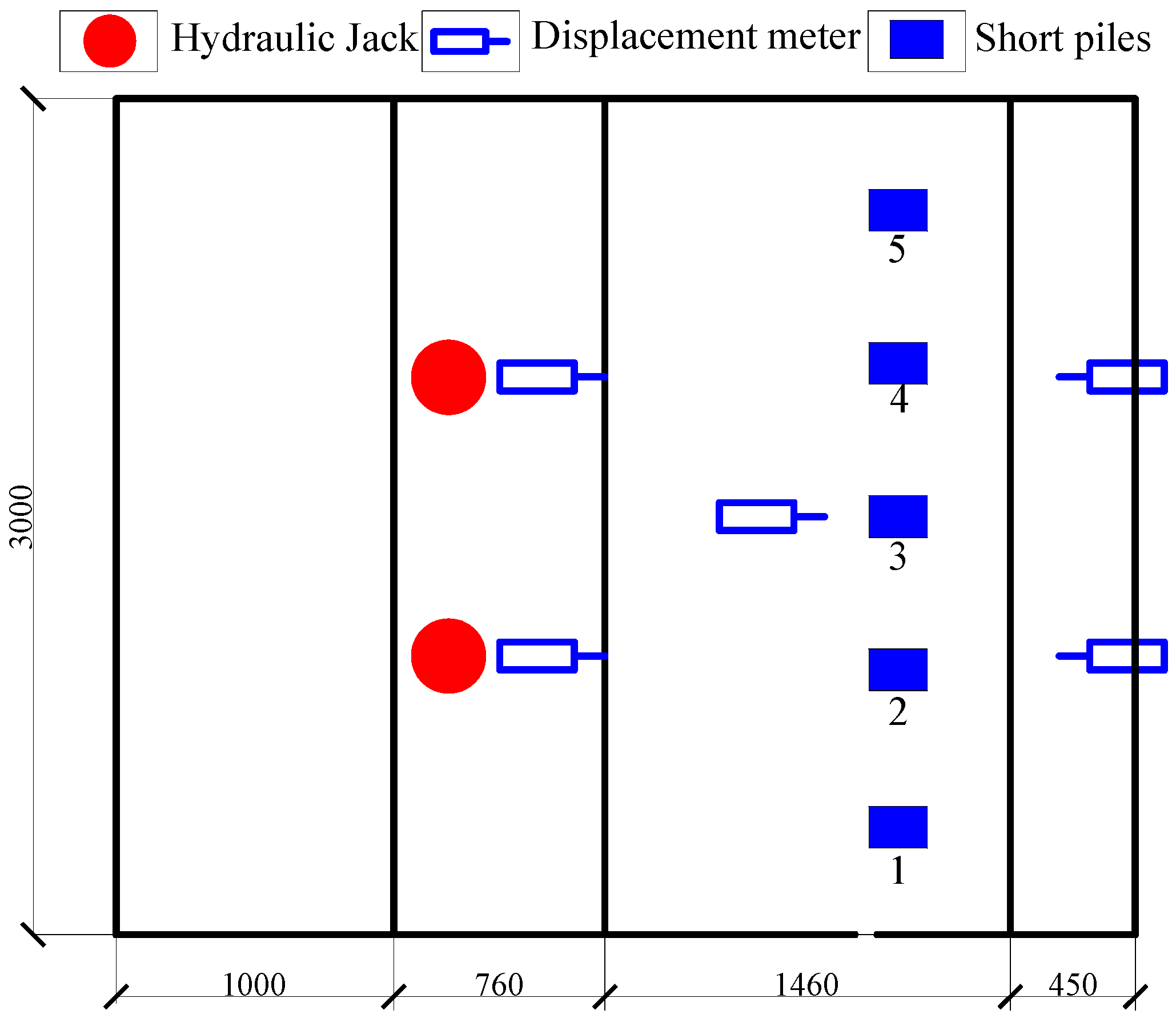
In the model experiments, a variety of measuring instruments and tools were utilized, such as resistance strain gauges, soil pressure cells, displacement meters, and more. The arrangement of these instruments is illustrated in the schematic diagrams presented in
Figure 7,
Figure 8 and
Figure 9.
The obtained strain data are based on the principles of moment calculation in materials mechanics. Utilizing Equation (30), it is possible to calculate the bending moment at different measurement points along the pile:
In the equation: EI—pile’s flexural stiffness, N·m²; ε+, ε−—tensile and compressive strains at various measuring points; x—distance between two measuring points on the same section, m; M—bending moment, N·m.
Calculating the derivative of the bending moment will result in the shear force along the pile:
The displacement measurement instrument employs rebound-type displacement sensors, offering a measurement accuracy of 0.01 mm.
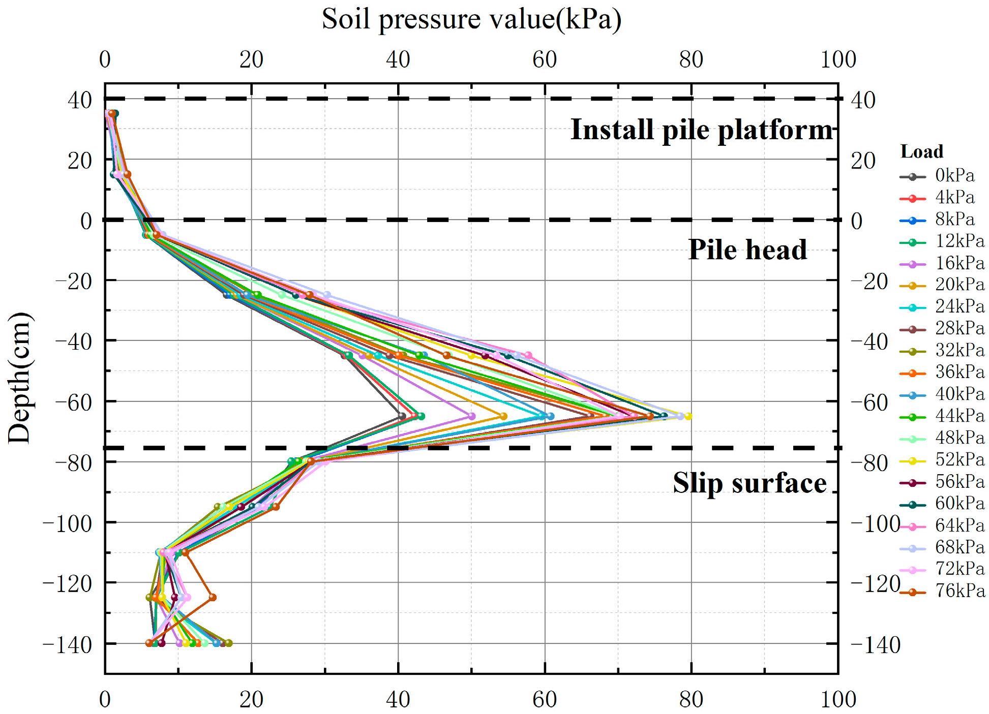
The distribution of soil pressure values obtained from the experiments is shown in the following
Figure 10:
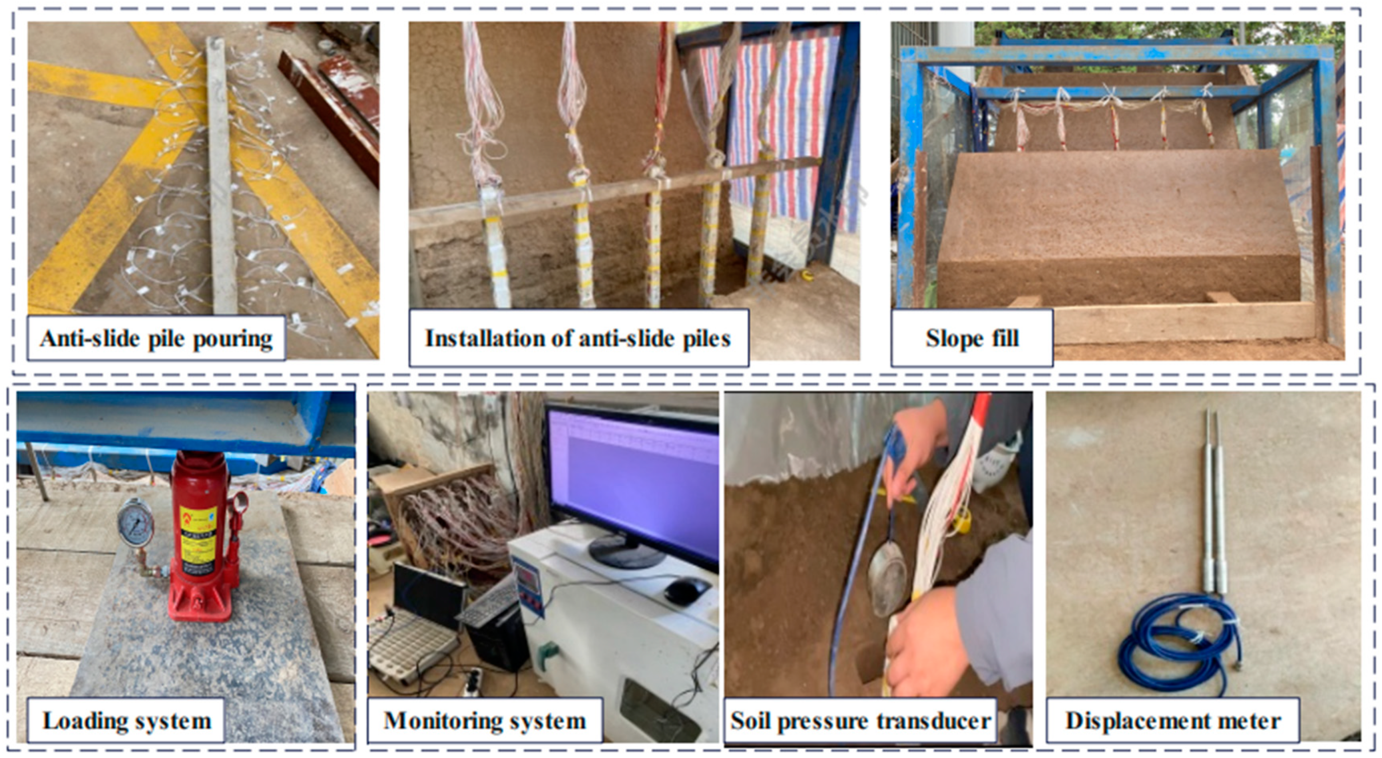
Figure 11 illustrates the selection of measurement instruments and the preparatory steps for the experimental setup. This includes casting and installing anti-sliding piles, creating the landslide model, and arranging loading devices, strain monitoring equipment, soil pressure boxes, and displacement gauges, as outlined in the preliminary phase of the experimental plan.
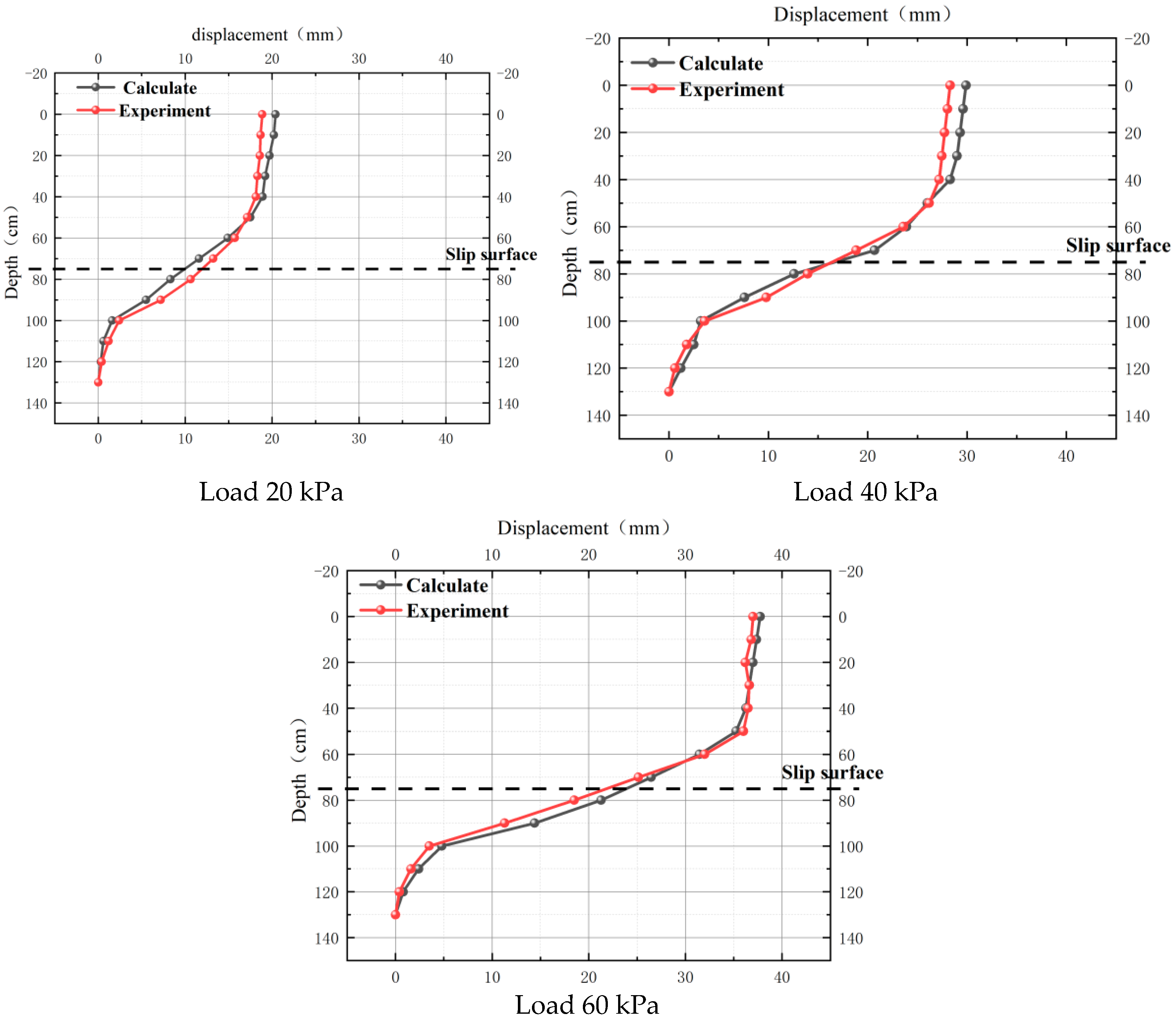
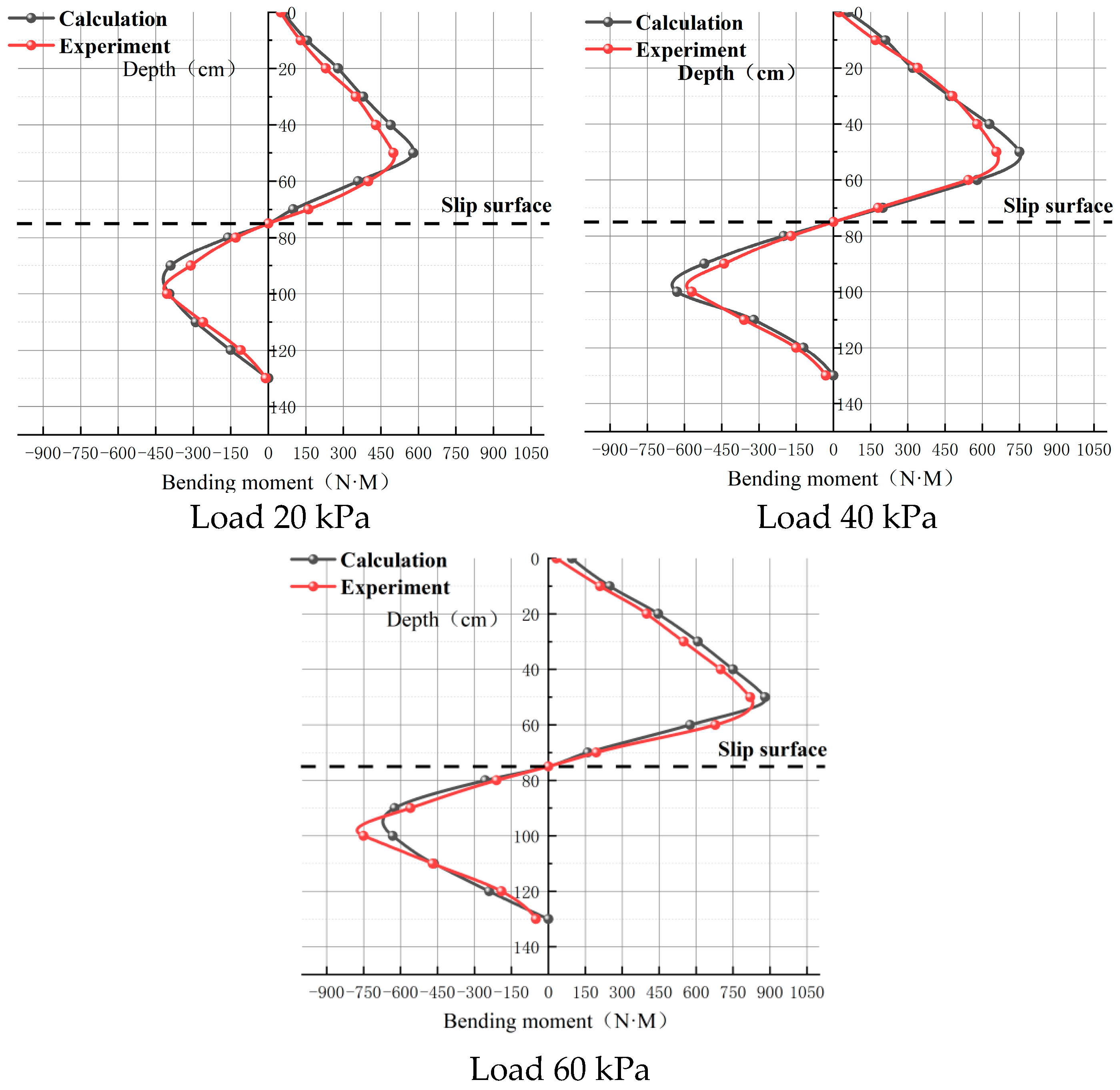
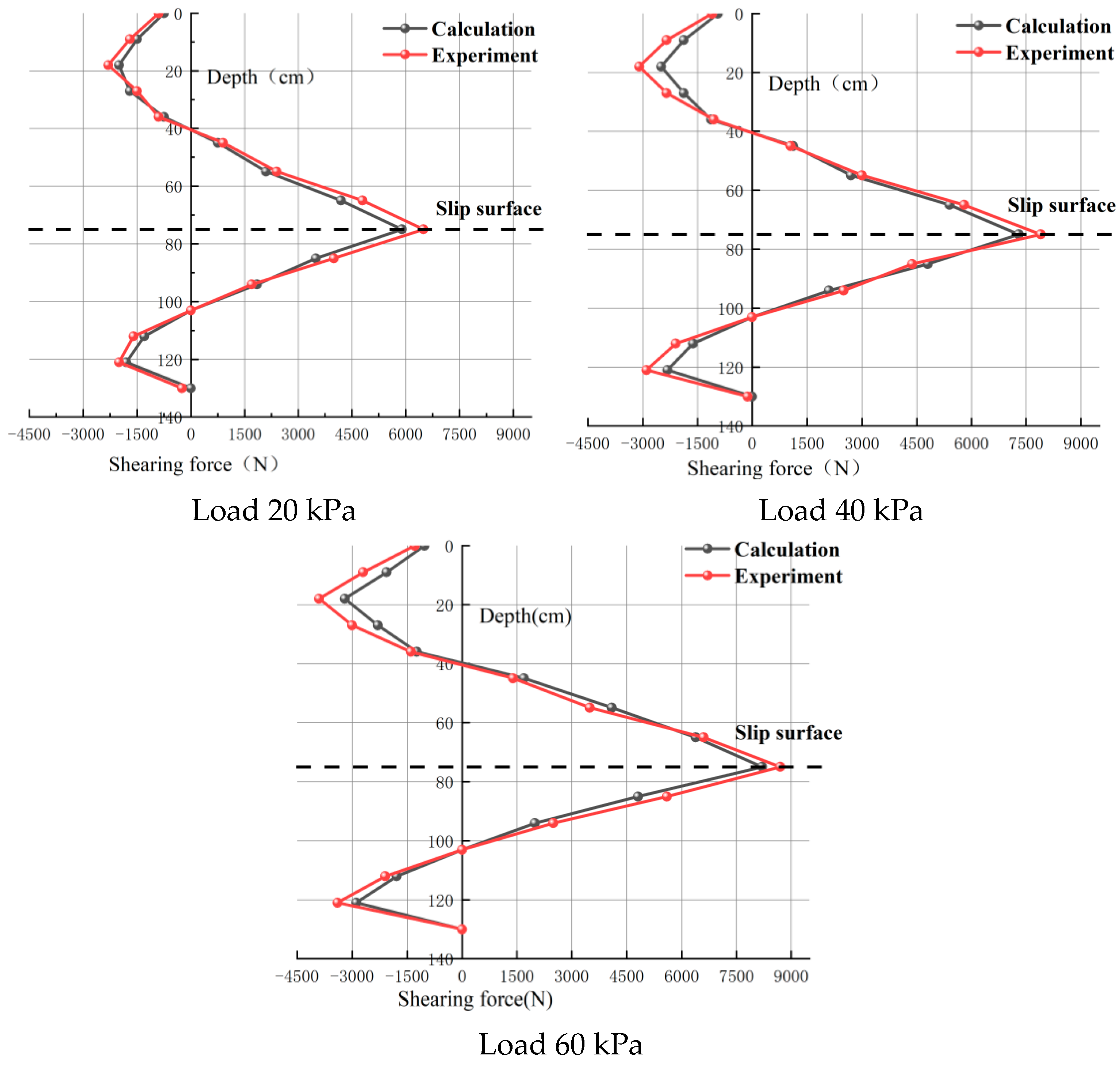
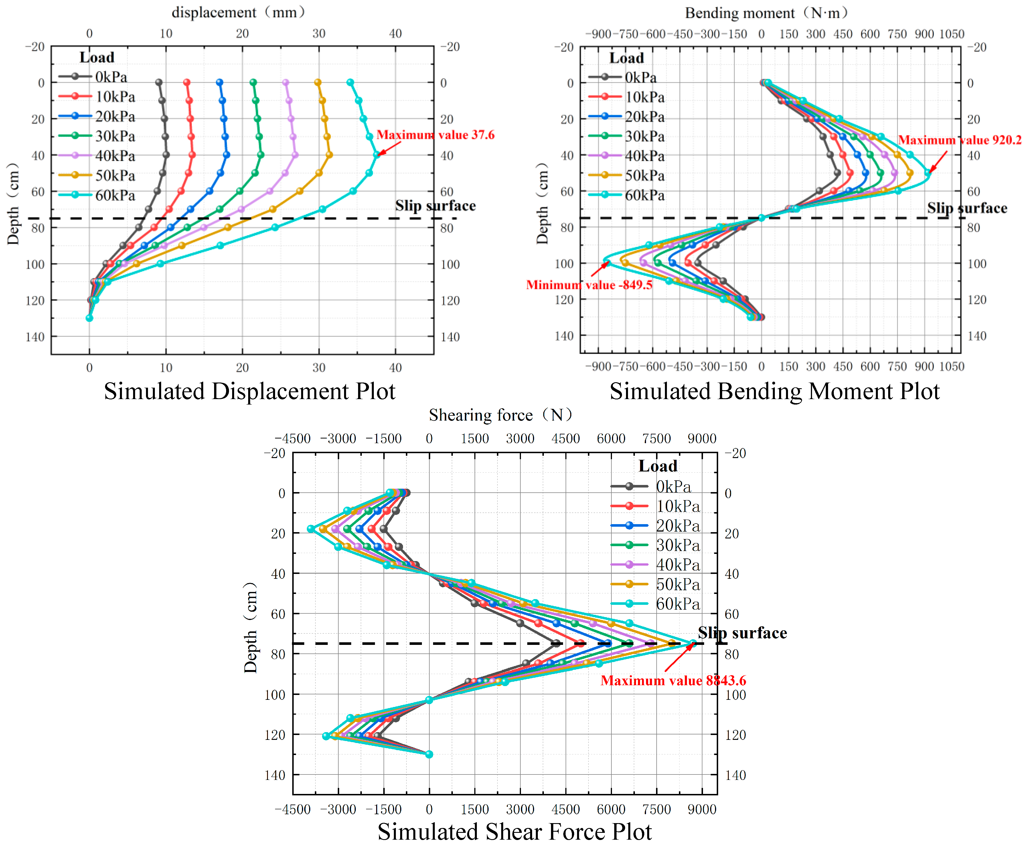
In the indoor model experiments designed to address landslides in loess regions, measurements were conducted for pile body soil pressure, pile stress, and slope displacement. The experimental data were compiled to discern the distribution patterns of pile body soil pressure and pile bending moment at different loading levels. Subsequently, using the experimental data as a basis, the same conditions were employed to calculate the overall internal forces of the pile, enabling a more scientifically grounded design for anti-sliding short piles.


