1. Introduction
Foams are materials produced by injecting air into a solid or liquid [
1,
2]. These systems are unique and significant for many fundamental questions and industrial applications [
3]. Some examples include the use of foam in cosmetic products [
4], food industries [
5], packaging [
6], noise absorption [
7], and firefighting [
8,
9]. Foams have also inspired many other fields, such as the sectors of design, art, and architecture, where new constructs are inspired by bubble assembly and structure. Some recent examples are the water cube swimming pool built for the 2008 Beijing Olympic Games, which became an iconic structure [
8]; Rotterdam’s solar-powered floating bubble pavilion; and Amazon’s bubble office building in Seattle. Moreover, foams are significant for multiple fundamental aspects. For example, mathematicians have strived to comprehend foam arrangements and how they maintain particular mathematical allures [
10,
11,
12], whereas physicists have attempted to understand foam assemblies and predict their properties [
13]. For these reasons, scientists and engineers are always looking for new ways to fabricate foams using different materials with various properties [
14,
15].
We can classify foams into two different categories based on their interfacial systems: foams that are separated by hard boundaries, called solid foams (air and solid) [
16], and those that are separated by fluid boundaries, called liquid foams (air and liquid) [
17]. In this paper, we focus on liquid foams that can be dry or wet depending on their volume fraction. The equilibrium configuration of these systems is determined by the minimization of their surface energy [
13]. For millimetric foams made of simple fluids, the pressure difference inside them is given by the Young–Laplace law
, where
is the surface tension of the film, and
R is the radius of the bubble. This difference is in the order of
Pa, which is very small compared to the atmospheric pressure (
PA). For this reason, liquid foams are considered incompressible. Their total energy is given by
, where
n is the number of bubbles in the foam, and
is the surface area of the bubble “
i”. This energy takes into account only the effect of the surface. Little is known about how other parameters, such as bulk elasticity and viscosity, could affect the properties of foams.
Liquid foams can assemble into different 3D structures as a function of various parameters, such as the system’s temperature [
18], the flow rate of the injected air [
19], the geometry of the given confinement [
20], and the system’s drainage properties [
21]. Among these well-organized assemblies, we can find the body-centered cubic (BCC or Kelvin) or the face-centered cubic (FCC) structures. These structures can affect foam stabilities and can be controlled via different experimental methods; by changing the volume fraction of the foam [
21], for example, or by controlling the geometry of the confining boundaries [
20], most of the previous studies have focused on the properties and structures of foams created by simple fluids. However, little is known about how foams arrange and pack when they are made by an ordered material such as a liquid crystal (LC).
LCs are condensed materials with properties between those of conventional liquids and those of traditional solids. Their molecules can be oriented like crystals; simultaneously, they can flow like liquids [
22]. Depending on the arrangements of these molecules, we distinguish different LC phases, such as nematics, smectics, and cholesterics. These materials are characterized by their anisotropic properties and delicate sensitivity to external stimuli, such as deformations, electric, and magnetic fields. For this reason, they are used in various applications, particularly in display devices, such as TVs, monitors, screens, smartphones, and watches [
23,
24]. They are also exploited in other material science applications, such as sensors, photovoltaics, and optoelectronics [
25,
26,
27,
28,
29]. Smectic material is one of the most important phases in LCs and is characterized by molecules assembled in parallel layers [
30]. The lamellar structure of smectics is similar to that of soap, making this material ideal for creating foams [
31,
32,
33]. Another advantage of using smectics is their strong elasticity and viscosity, which helps to stabilize foams, especially when it comes to the effect of drainage, for which soap foams are influenced heavily by the gravity field [
21,
34]. In this work, we emphasize the boundary effects to study how geometric confinement and elasticity affect the structure of 3D smectic foams. We chose to work with the 8CB LC (4′-octyl-4-biphenylcarbonitril) because this material presents a smectic A phase at room temperatures and a nematic phase at higher ones. The coexistence of both mesophases was found to be essential for the creation and stabilization of LC foams. We discuss how the airflow rates influence their properties, such as overall organization and stability. We also compare the behavior of LC foams to those made with an isotropic detergent, the sodium dodecyl sulfate (SDS), and discuss the advantage of using LCs to fabricate foams.
2. Materials and Methods
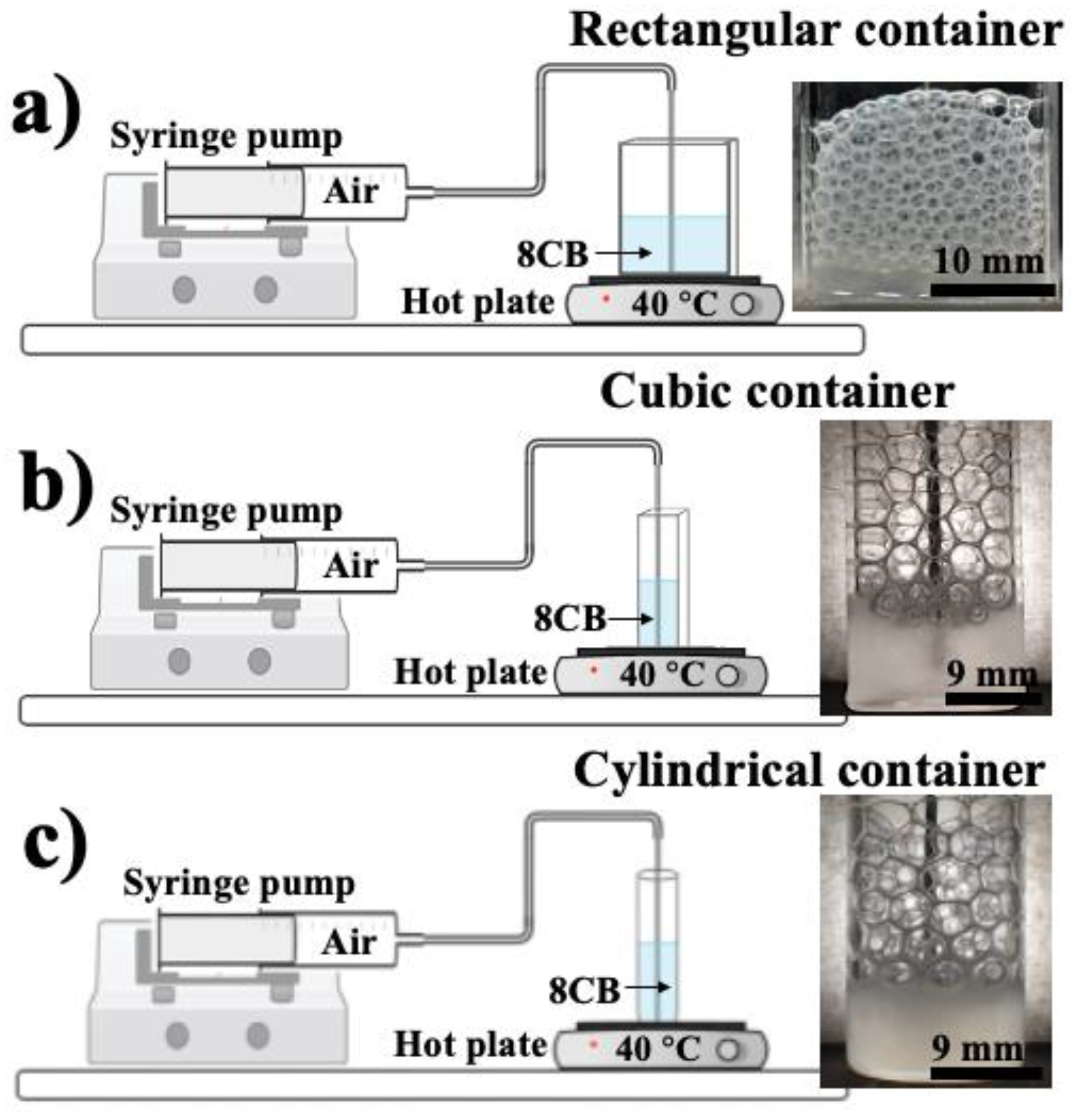
To study the effect of geometric confinements and airflow rates on the fabrication of 3D smectic foams and the assembly of their cells, we utilized cylindrical, square, and rectangular containers, as shown in
Figure 1. We used glass containers to help visualize the foam’s inner structure. The procedure and preparation methods for the foam fabrication under these different confinements were similar. We utilized the 8CB LC (4′-octyl-4-biphenylcarbonitril, purchased from Kingston Chemicals Limited), which exhibits a crystal phase below 22 °C, a smectic phase between 22 °C and 34 °C, a nematic phase between 34 °C and 42 °C, and an isotropic phase starting at 42 °C, because this material presents a smectic A phase at room temperature. A syringe pump (from KD Scientific) was used with a 30 mL syringe connected to a 19 g × 3” needle (from Cadence Science, Inc., Cranston, RI, USA) via polyethylene tubing (from BD Intramedic, I.D. 1.14 mm, O.D. 1.57 mm) for a consistent airflow with rates varying between 2 mL/min and 62 mL/min. The rectangular container was constructed from glass slides with a length of 25 mm and a width of 6 mm (base area of
150 mm
2). The square container was a square glass vial with a side length of 15.78 mm (base area of
250 mm
2). The cylindrical container was a glass vial with a base area of
230 mm
2. A similar initial amount of smectic LC was placed inside these three containers.
To fabricate the foam, a hot plate (from Fisher Scientific, Waltham, MA, USA) was used at 40 °C to keep the LC near the isotropic–nematic phase transition temperature and reduce the high viscosity of the 8CB at room temperature. Since the containers are also in contact with air, a temperature gradient is then created in the LC. This gradient also induces a viscosity gradient in the LC, with lower values near the bottom (hot surface) and higher ones near the smectic–air interface (cold air). These gradients were found to be very helpful for fabricating and stabilizing the LC bubbles.
The air was injected into the samples by using a needle placed in their centers, near the bottom. We adjusted the airflow rate from 2 mL/min up to 62 mL/min to study the effect of airflow rate on the properties of the foam. When the bubble was formed at the bottom of the container, where the LC was in the nematic phase, it moved up to the interface in contact with air and cooled down to the smectic phase. After the foam grew to an optimal height, the hot plate and the syringe pump were turned off, allowing the entire sample to cool down to the smectic phase at a temperature around 22 ± 2 °C. Our analysis started after we ensured that the sample was stable and its temperature was homogenous. For SDS foams, we prepared three solutions with three different concentrations (0.1 wt%, 0.5 wt%, and 1 wt% of SDS in water) to create regular soap foams under the same geometric confinements and airflow rates. A digital camera (Nikon D5600) was used to capture the structure of the foam in the LC and SDS.
To better understand the difference between the isotropic liquid and anisotropic smectic foams, as well as how the geometric confinement and the airflow rates affect their properties, we used the technique of image processing (ImageJ software version 1.53 t) to measure some essential parameters of the foams, such as the cell area near the glass walls, thicknesses, and 3D symmetry. Pictures taken from the digital camera were transformed into 8-bit black-and-white images, and the appropriate threshold values were set for the best analysis of the results. All cells in each image were analyzed individually, and their properties were extracted. To minimize error analysis, the foams that were in contact with the container boundary were neglected, and only the central parts of the foams were considered for image processing. All quantitative data collected from ImageJ were plotted using the software Origin.
3. Results
Fabrication and creation of the foams: With the setup described above, we successfully fabricated the foam in the three containers with different geometries, with airflow rates changing from 2 mL/min to 62 mL/min. The experimental results show that the LC foams cannot be created in the pure smectic or nematic phases. The reason is that the 8CB material is too viscous in the smectic phase. Therefore, the bubbles could not be fabricated due to the strong elasticity preventing them from forming. When the 8CB is in the nematic phase, we can create bubbles. However, they are unstable. They collapse immediately due to the lack of the lamellar structure in the LC film. Our solution to generate stable foams was to create bubbles in a container with a temperature gradient; a nematic phase near the bottom, where air is injected; and a smectic phase near the interface, where the bubbles are packed. This helps to reduce the viscosity of the 8CB, where bubbles are created, and stabilize them via the lamellar structure, where they are packed. For simple fluid foams, we found that the concentration difference of SDS does not lead to fundamental changes in the sample properties, except that the higher concentration enhances the creation of bubbles. For this reason, we focused on SDS samples with 1 wt% concentrations in this study.
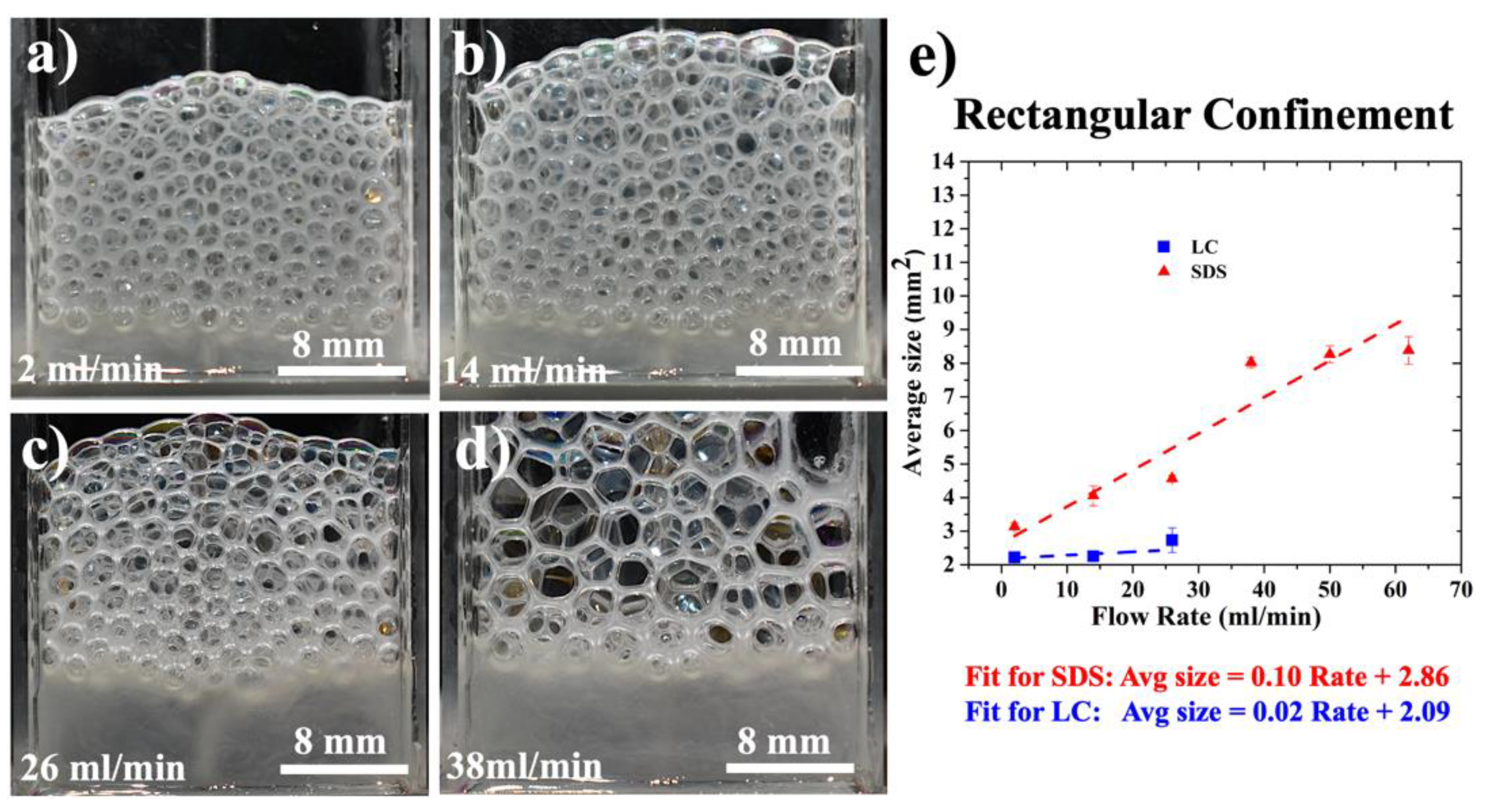
Rectangular confinement: The goal of fabricating foams in rectangular containers is to understand how geometric confinement will affect the properties of LC foams under different airflow rates. We started with an airflow rate of 2 mL/min, as shown in
Figure 2a. In this case, the LC bubbles pack and line up nicely, similar to the bubbles generated from the SDS solution (
Supplementary Figure S1a). In addition, they are stable for about two hours. Their overall size near the container wall is almost uniform, with an average area of ~2.21 ± 0.049 mm
2. However, their shapes change from circular near the LC reservoir (bottom of the foam) to polygonal (hexagon) near the smectic–air interface. This result indicates that the foam volume fraction, usually affected by the drainage due to gravity, plays a vital role in the formation and assembly of LC bubbles. Here we analyze the 2D projection of cells at the wall container to predict the behavior of cells in bulk because studying foams in 3D is complex experimentally.
When the airflow rate is increased to 14 mL/min, we found a slight increase in the size of cells (from 2.21 ± 0.05 mm
2 to 2.247 ± 0.13 mm
2). However, there is no significant difference in their characteristics (see
Figure 2b), except for slightly diminished stability to approximately one hour. The cells are still well organized with better-defined polygonal shapes near the smectic–air interface. If the airflow rate is increased to 26 mL/min, we start to see some polydispersity in cell size and irregularity in their organization, as shown in
Figure 2c (average area of ~2.73 ± 0.37 mm
2). At 38 mL/min, all bubbles become random, and no more regularity can be observed in the sample, as shown in
Figure 2d. When we continued to increase the airflow rate beyond 38 mL/min, we found that the LC foams could no longer be fabricated because their cells could not hold and would collapse quickly.
To study the difference between an ordered fluid and an isotropic material, SDS foams were fabricated in the same conditions and were compared to LC ones, as shown in
Supplementary Figure S1. We first noticed that the regularity of both LC and SDS systems is similar at low airflow rates. Secondly, we found that the overall size of SDS cells increases linearly with the airflow rate, like LC cells. However, SDS cells are always bigger than LC cells (
Figure 2e). The slope of the linear fit for the cell sizes versus the airflow rates is more significant for the SDS than the LC (larger by five times). Additionally, we found that it is possible to fabricate SDS foams with highly regular patterns beyond the smectic threshold airflow rate of 38 mL/min. The possibility to fabricate SDS foams beyond the airflow rate of 38 mL/min is due to SDS’s absence of LC elasticity that prevents smectic bubbles from forming at higher rates.
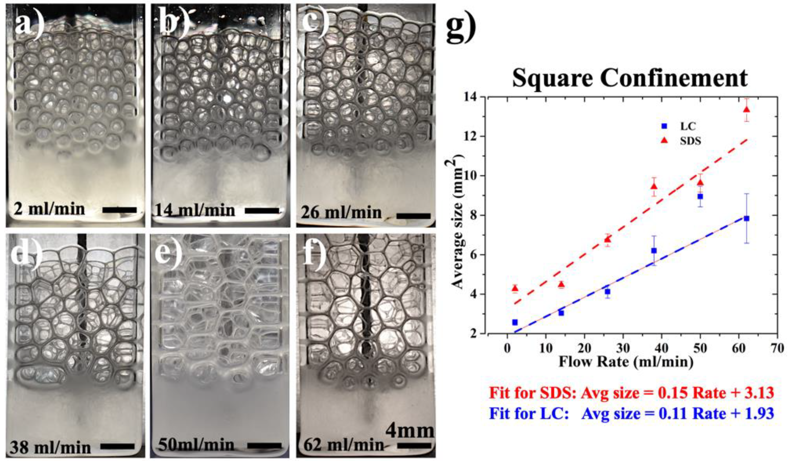
Square confinement: When the LC foam was fabricated in square containers, we found that it was possible to increase the airflow rate from 2 mL/min to 62 mL/min, as shown in
Figure 3, unlike the previous case of rectangular confinement. Within the low airflow region (2 mL/min, 14 mL/min, and 26 mL/min), smectic cells present polygonal structures with no significant difference in size and organization (
Figure 3a–c, respectively). They are stable for about one hour at room temperature. When the airflow was increased to 38 mL/min, we observed the formation of large bubbles with some defects in their assembly, as shown in
Figure 3d. The large bubble formation is due to the fact that some cells collapse after we create the foam. Despite this irregularity, we still have organized packaging compared to LC foams confined in rectangular containers. When the airflow rate is increased to 38 mL/min, 50 mL/min, and 62 mL/min (
Figure 3d–f), the smectic foams start to create more polygonal structures, indicating that the volume fraction of the foam is decreasing (thinner 8CB films between the cells). The overall size of the foam continues to grow with the airflow rate, as shown in
Figure 3g. We also found that the system’s durability weakens because the foams are less stable and collapse quickly after five to ten minutes. We note here that all samples prepared in the square containers present better regularity than those fabricated in rectangular ones, thus confirming the foam’s sensitivity to the geometry of their boundaries.
For SDS foams fabricated in the same conditions, we found that they have highly ordered structures under different airflow rates (from 2 mL/min to 62 mL/min), as shown in
Supplementary Figure S2. Additionally, they have better regularity than the smectic foams, particularly at higher airflow rates. The SDS cells show fewer deformations than the ones in LC, but their durability is much shorter (around 20 min).
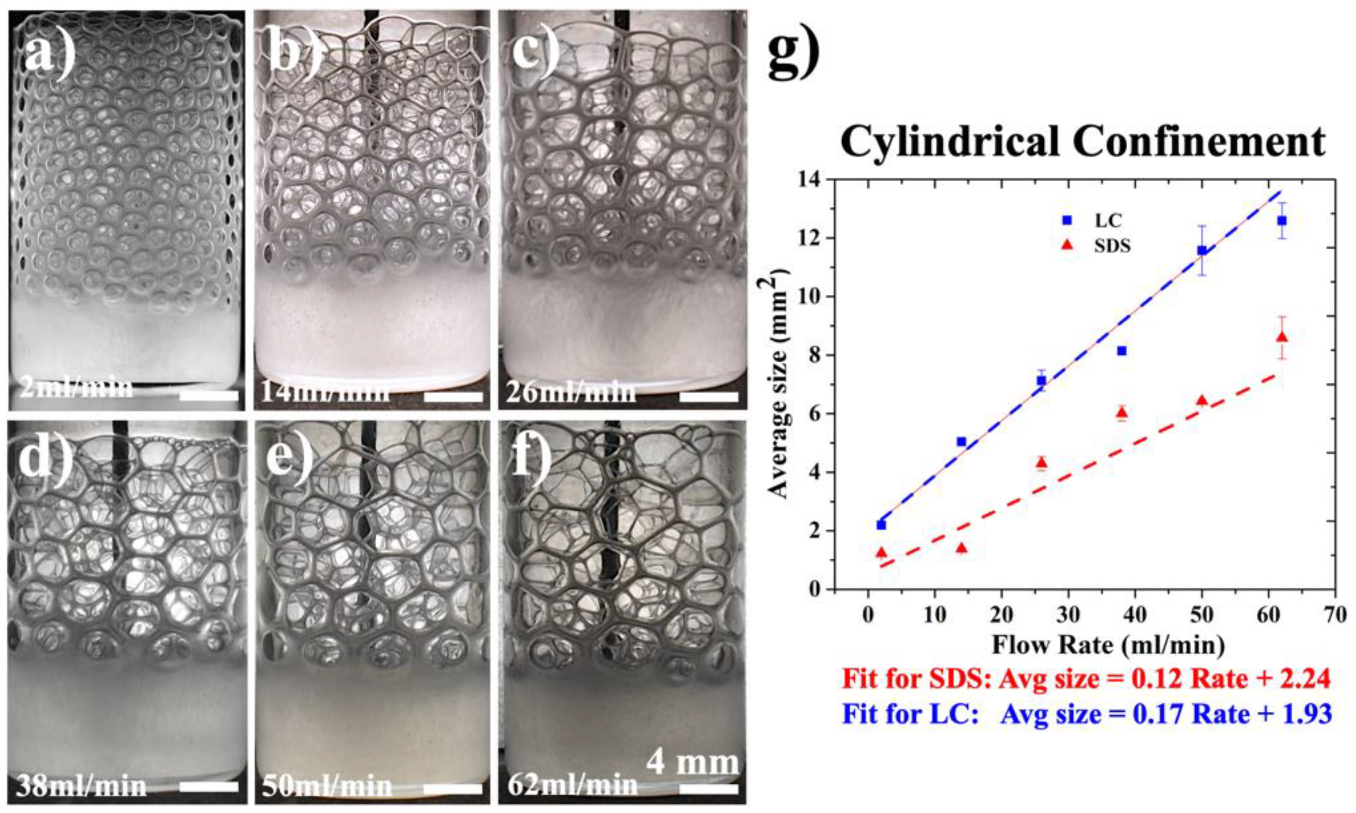
Cylindrical confinement: Our results show that the most optimal structures among all three confinements in terms of regularity and stability are obtained using the cylindrical containers for both the SDS and LC foams, as shown in
Figure 4 and
Supplementary Figure S3. At 2 mL/min (
Figure 4a), the cells show a perfect polygonal arrangement near the glass wall. They are stable for more than 2 h for the LC and an hour and a half for the SDS. When the airflow rate is increased to 14 mL/min (
Figure 4b), we observe a significant growth in the size of the smectic cells from 2.187 ± 0.03 mm
2 to 5.04 ± 0.03 mm
2, as shown in
Figure 4b. At higher flow rates, 26 mL/min and 38 mL/min (
Figure 4c,d), the bubble size expands, causing cells’ distortions, which affect their structure and organization. If we continue to increase the airflow rate, we obtain less stable foams with distorted structures, as shown in
Figure 4e,f (lifetime is about 15 min).
Unlike the smectic, SDS foams created in cylindrical containers show higher regularity at all airflow rates, ranging from 2 mL/min to 62 mL/min (
Supplementary Figure S3). However, their growth rate is much slower than the smectic ones (
Figure 4g). This is different from the cases of rectangular and square containers. Additionally, they are less stable than the LC foams. These results confirm the coupling between the bulk properties of the materials used to create the foam (e.g., elasticity and viscosity) and the boundary conditions (such as the geometry of confinement) in the process of assembling stable 3D foams.
4. Discussion
Based on the experimental results presented in the previous section, we concluded that the properties of SDS and LC foams are significantly affected by the geometry of the boundaries, the flow rate of the injected air, and the drainage properties of the foam. For example, we found that we could improve the foam structures and their stability by changing the shape of their container from rectangular and square to cylindrical. This is because the confining forces in the cylindrical geometries are radial and symmetric, unlike the anisotropic ones in rectangular and square containers. These radial forces apply uniform pressure that helps support the foams at high airflow rates while organizing and stabilizing them. We also found that the material’s elastic properties can play an essential role in foam fabrication and assembly processes. When the air is injected into the LC, it induces a deformation of the smectic film to generate a bubble. This deformation is usually energetically expensive. To minimize the excess of the free energy, the elasticity of the LC (bulk effect) and its surface tension (at the smectic–air interface) resist the forces produced by the air and balance them. This is why the size of 8CB cells is smaller than that of SDS because the elasticity of SDS is negligible compared to that of LC (
Figure 2e and
Figure 3g). This is also why the smectic cells are deformed at high airflow rates and why we cannot create foams above 38 mL/min in rectangular containers (
Figure 2d). However, it is essential to mention that the size effect is valid only for rectangular and square confinements where the pressure forces are anisotropic. In the case of cylindrical boundaries, the opposite behavior is observed: the LC cells are larger than those of SDS (
Figure 4g). We believe that this is due to the interplay between the radial confining forces and the elastic ones that create a resultant force that supports the cells, stabilizes them, and helps them to grow, unlike rectangular and square containers, where the confining pressures and elastic forces are anisotropic, causing the bubbles to bump and collapse. The LC bubbles can then support a larger volume of air, while the SDS ones can be created with a lower air volume, which explains why these cells are smaller than the LC ones in cylindrical containers. By analyzing the effect of the airflow rate and the geometry of confinement, and by comparing the smectic foam to SDS, we concluded that the best parameters to fabricate stable and ordered LC foam are in a cylindrical container at an airflow rate of 2 mL/min. We next focused on the 3D structure of the foams and the assembly of their cells.
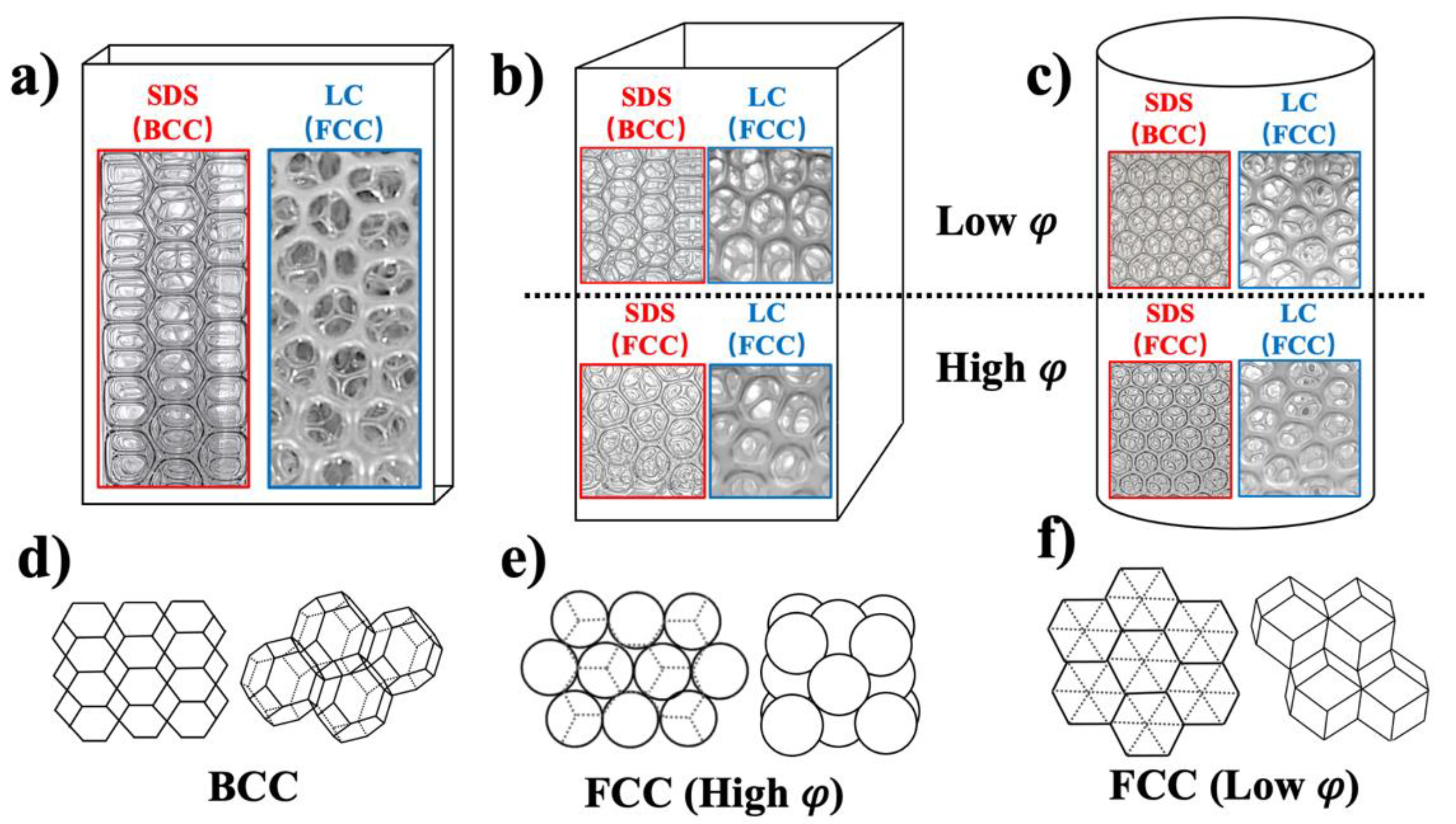
Figure 5 shows the different 3D assemblies of the SDS and LC foams under different geometric confinements. Our results indicate that the structure of foams depends on three parameters: The first one is the drainage of the foam that affects their cell thicknesses and shapes. The second one is the confinement conditions. The third one is the elastic properties of the materials. To better understand the drainage effect due to gravity, we measured the change in foam-cell thickness between the upper layer (in contact with the air) and the lower one (in contact with the material reservoir), as shown in
Supplementary Figure S4. We found that the change in cell thickness within rectangular geometries is more significant for the SDS (57 ± 2%) than the LC (40 ± 1%) (
Supplementary Figure S4a). We also noticed that the drainage does not depend on the flow rate of the injected air. In rectangular confinement, all cells have a polyhedral shape and present BCC symmetry (
Figure 5d) in the case of SDS and FCC (
Figure 5f) in the case of LC (
Figure 5a).
When the geometry of confinement was changed to a square (
Figure 5b), we noticed that the shape and the arrangement of SDS cells were affected by the drainage of the foam. Two limits were found in this configuration: The first one is with a low volume fraction,
, in which cells are dry, polyhedral, and packed in a BCC structure (
Figure 5d). The second limit is with a high volume fraction,
, in which cells are wet, spherical, and packed in an FCC structure (
Figure 5e). The same observations were noticed in the case of cylindrical containers (
Figure 5c), except for the shape of the cells at a high volume fraction,
, which were found to be polyhedral and not spherical like in the square container. These results confirm the role of drainage and confinement conditions on the assembly of foams that are made with simple fluids. They also show the sensitivity of these foams in relation to their fabrication process. However, this is not the case for the LC foam, where cells always have a polyhedral shape and are packed in an FCC structure, independently of their volume fraction, drainage, or confinement geometry.
Our results indicate that LC cells are always packed with FCC symmetry due to the LC’s strong elasticity, which balances the containers’ confining forces. This property can be considered an asset for fabricating foams in industrial applications, where uniformity in size and symmetry are required.


