Article

Low-Profile FSS Design Methodology to Increase Isolation between Vehicle-Borne Multifrequency Antennas

Tecnun-School of Engineering, University of Navarra, 20018 San Sebastián, Spain
*
Author to whom correspondence should be addressed.
Appl. Sci. 2023, 13(7), 4187; https://doi.org/10.3390/app13074187
Submission received: 20 February 2023 / Revised: 21 March 2023 / Accepted: 23 March 2023 / Published: 25 March 2023
(This article belongs to the Section Electrical, Electronics and Communications Engineering)

Abstract

:
The present work describes a new approach for the design of a Frequency-Selective Surface (FSS) in the context of frequency filters to increase isolation between two vehicle-borne antennas. A compact FSS design based on nested square meandered resonators is optimized for multifrequency operation. Furthermore, a design workflow is proposed. In general, the measurement of low-profile FSS does not correspond to simulation through Floquet modes based on periodic boundary conditions due to the lack of uniformity of mutual coupling among the FSS unit cells. The proposed method demonstrates the agreement between the infinite simulation and the measurement of the finite prototype once a convenient scale factor is applied, which facilitates the design workflow. In this case, an FSS is used as an efficient filter to increase the isolation between antennas by 6 dB in three representative bands (3GPP, WiFI I and II). In this way, multifrequency antennas can be placed at approximately half their actual distance with the same performance in spatial-constrained vehicular environments.

1. Introduction

With the increasing development of wireless technology, the need for multiple antennas in wireless systems has arisen to provide a growing number of wireless services, such as WiFi, Bluetooth, 4G and 5G mobile telephony, GPS and others [1,2,3]. As a consequence, the space between multiple antenna systems is often increasingly reduced. This reduction in distance is especially unavoidable when the available space is limited, such as in mobile, autonomous vehicles and rolling stock. Thus, mutual coupling between antennas significantly increases. This can lead to sacrificing the performance of the antennas, which diminishes the data rate or the dynamic range of communication systems [2,4]. In the particular case of rolling stock, recent studies recommend a separation distance of 2 m for proper interoperability [5,6]. However, in the manufacturing workflow, rooftop antennas are installed after the electric equipment is in place (e.g., pantograph, air conditioning cabinets, etc.). This fact often forces the distance between antennas to be below the limit where the antenna manufacturer defined compliance with the requirements. If QoS is degraded, a situation arises where it is difficult to state the limits of liability. A decoupling method without affecting the antenna installation is therefore required in these instances.
In recent years, significant attention has been paid to mitigating mutual coupling interference in a multiple antenna system [1,3,7,8,9,10]. For this purpose, many decoupling techniques have been proposed: decoupling networks [9,11,12,13], neutralization lines [2,14], parasitic resonant elements [15], defected ground structures [16], pattern diversity [1,17], metamaterials [18,19,20,21,22] and others [10,23,24]. Although these methods can effectively suppress surface wave propagation and achieve high isolation between antennas, most are antenna-dependent, related to single-band applications and come with some constraints and complexity [9]. Moreover, these methods often involve changing previously installed antennas, which increases costs. Hence, a desirable approach would be to achieve isolation in a non-complex manner, regardless of the type of antenna, which is suitable for both single and multiple-band applications. In this context, decoupling based on a Frequency Selective Surface (FSS) is studied [25,26,27]. This method is not antenna-dependent and can be used for several bands.
FSSs have been commonly used in radio frequency systems in applications as diverse as microwave ovens, antenna radomes [28], modern metamaterials and radars [4]. An FSS can be added between the antennas to reduce coupling, as shown in Figure 1. It typically consists of a periodic array of printed resonators on a dielectric substrate. FSS acts as a frequency filter between the antennas because it is composed of resonant structures that absorb the energy at certain frequencies. The geometry of the resonator will determine its frequency response, while the array size and the interspace between resonators impact the final attenuation.
Figure 1. Operating principle of the Frequency-Selective Surface.
Applsci 13 04187 g001
In the proposed scenario, the FSS is placed perpendicularly to the rooftop of a vehicle (e.g., train) between two multifrequency antennas. A low-profile FSS is convenient for greater clearance and to avoid high impact on the general 3D radiation patterns of the antennas. The actual FSS size will be a trade-off between the aforementioned downsides and the filtering capability, which increases with the FSS cross-section.
For a low-profile FSS design, the size of each resonator or the number of them must be reduced. Regarding the size of the resonator, different sizes and designs of compact resonators are studied in [28,29]. Other investigations deal with reducing the resonator size using discrete components [30]. In terms of the number of elements, simulation methods are often based on infinite array approximation using Floquet modes and reducing the computation domain to a unit cell with periodic boundary conditions. This approach is closer to a filtering problem between the two sides of the FSS than open boundary conditions, as the former provides reflection and transmission parameters. This is no longer possible if a finite FSS is considered because a general transmission coefficient cannot be set. However, unit cell approximation ignores the influence of the edge effect on the isolation due to the actual finite size of the FSS structure. In a finite FSS design, the resonators of the array that are closer to the boundaries are surrounded by air, whereas, in its infinite simulation, they are all equally surrounded by other resonator elements. Then, a discrepancy between infinite (simulated) and finite (measured) FSS is likely to occur unless the resonators are far enough apart to be considered as not influencing one another. If this happens, the infinite FSS simulation should match the finite FSS measurement. However, this is not convenient because it increases the size of the FSS design. Therefore, a convenient strategy should be provided by selecting the advantages of unit cell simulation with periodic boundaries that could be applicable to a finite structure for a low-profile FSS.
In this paper, a new Meander Square Nested Resonator (MSNR) is proposed for a compact FSS design, along with a methodology to expedite its design process when placed between multifrequency antennas. This goal will be achieved by taking advantage of the simplicity of unit cell boundary conditions and Floquet mode calculation for an infinite FSS structure. The dimensions of the resonator for the infinite simulation will be correlated to the resonator dimensions of a real (limited) FSS prototype by a scale factor exclusively derived from simulations. This factor will make up for the differences between finite and infinite boundary conditions. The final solution should be low-profile to avoid high impact in the radiation pattern of the antennas. Furthermore, this work aims at isolating several bands of operation in a multi-standard system using a multi-band FSS.
This paper is organized as follows: Section 2 discusses the design methodology for a compact low-profile FSS, Section 3 presents the implementation and results and Section 4 gives the conclusions.

2. Design Methodology

This section describes the methodology for designing a low-profile FSS to improve isolation between two vehicle-borne multifrequency antennas.

2.1. Bands of the Multifrequency System

The considered frequency bands to be attenuated are shown in Table 1. The study can be easily applicable to other bands. As a design strategy, the first two bands are grouped. Therefore, two main bands are addressed and implemented in an FSS composed of two resonators, one for each band.

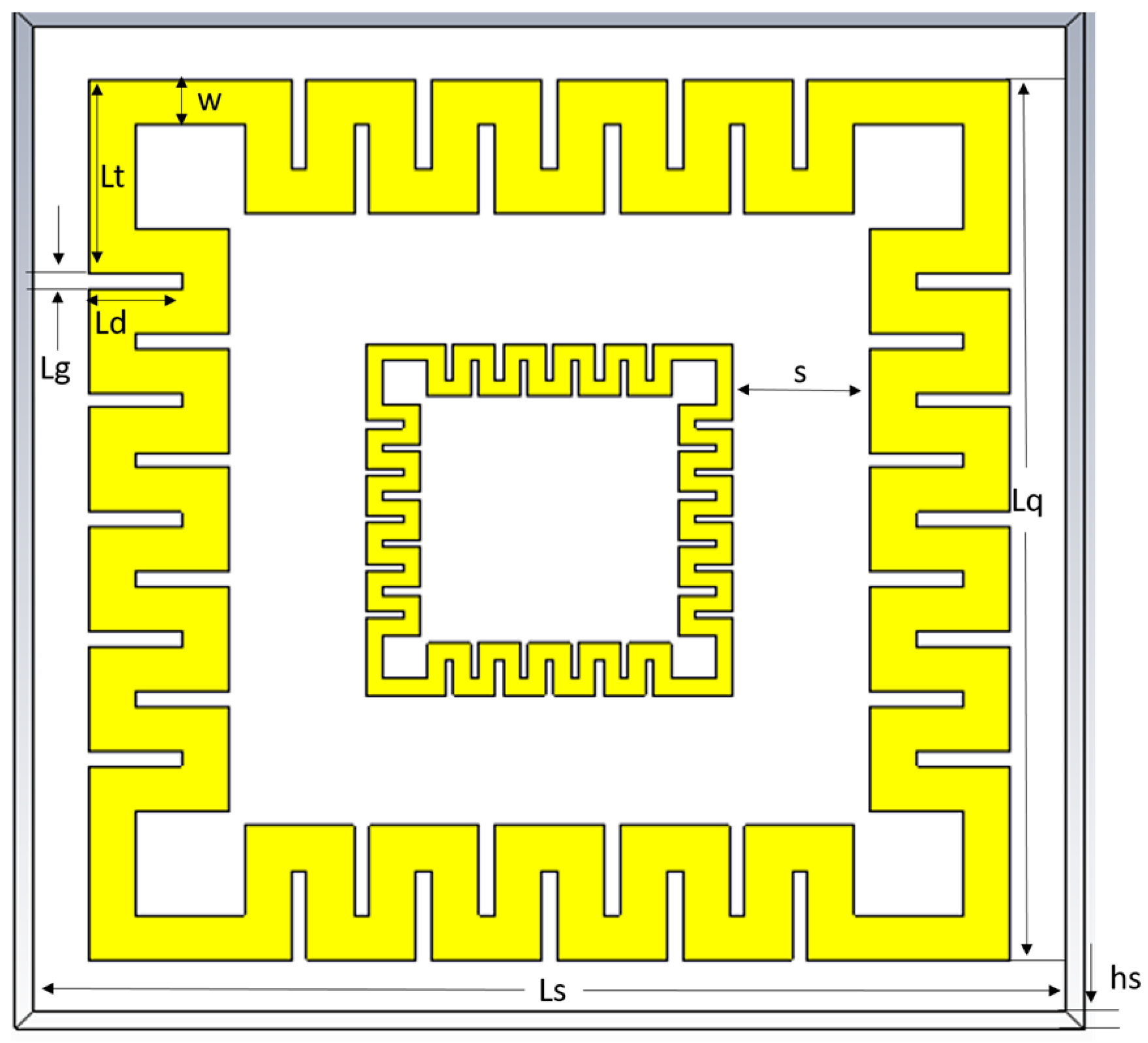
2.2. Proposed Compact FSS Topology

The unit cell design, composed of a new Meander Square Nested Resonator (MSNR), is proposed in Figure 2, where Ls and hs are the length of the square unit cell and the thickness of the substrate, respectively; Lq is the length of the FSS square structure; Lt, Ld and Lg are the meander-line dimensions (length, depth and gap); s is the space between the needed square loops and w is the line width.
The proposed MSNR draws inspiration from the Hilbert curve [31,32]. This fractal structure has a particular compact size and therefore exhibits a small electrical size of the overall surface when compared to the wavelength of the operating resonant frequency. However, two main downsides are now addressed for this particular application. Firstly, due to the asymmetry of the Hilbert curve, dual polarization cannot be achieved at the same frequency. To overcome this issue, the MSNR is a closed structure without any opening, which makes it dual-polarized in its filtering capabilities. Secondly, while traditional Hilbert curve designs occupy the internal space of the structure, MSNR concentric feature enables nested resonator accommodation and, therefore, multiband performance. In this way, the MSNR exhibits similar compactness to the Hilbert curve but with dual-polarization and multiband features.
The FSS design simulation is generally carried out using the unit cell boundary condition, which virtually repeats the modeled structure periodically in two directions up to infinity. When Floquet modes are used to solve FSS scattering, the induced currents are uniform across the array excited with a plane wave. In CST software, this can be implemented as shown in Figure 3, where Γ and T are the reflection and transmission coefficients, respectively.
The unit cell can be defined as the basic building block of the array and repeats itself in simulation infinitely with periodicity Dx, Dy. The simulation, based on Floquet modes, imposes that all the elements of the infinite array are identical. As the space among the elements of the array should be reduced as much as possible to achieve a compact low-profile FSS, the mutual coupling between the elements must be considered.

2.3. Critical Design Parameters

In this section, the process from simulation to final design is described. The length of the square of the outer resonator is essential to obtain the correct resonant frequency at the center of the lower bands. Therefore, a sweep of the Lq parameter is performed, as shown in Figure 4, which influences the meander-line dimensions. Using meanders in a design allows for a decrease in the resonance frequency without altering the cell size, making them an effective tool for fine-tuning the design to meet desired performance requirements.
Designs with a square length from Lq = 29 mm to Lq = 31 mm would be candidates to cover the lower frequency bands (3GPP and WiFi I, highlighted in grey). As it will shown later, the effect of the second nested resonator will shift further down the filtering frequency, and therefore Lq = 29 mm is selected to make up the envisaged effect. Although a compact design was achieved with only one resonator, another resonator dedicated specifically to the WiFi II band was added. The new resonator is an exact copy of the first resonator, where its dimensions are scaled and reduced to obtain a filter response in the frequency of the wide WiFi II band.
The inner resonator was adjusted using a size reduction coefficient, as shown in Figure 5. This coefficient was estimated by the ratio between the resonant frequency of the previous design and the center of the second band, which is 5.5 GHz. The resulting size reduction coefficient is found to be 0.39.
The figure shows a scale factor parameter sweep around the estimated value to corroborate the hypothesis and test the impact of the mutual coupling corresponding to the nested architecture. As can be seen in Figure 5, if the scale factor is set lower than the calculated parameter, the frequency will overlap with the outer harmonic at the end of the desired band (black line). On the other hand, if the scale factor is set too high, the resonant frequency will be outside the desired band (blue line). Thus, the reduction coefficient of 0.39 turns out to be optimal for this band rejection. This setting causes the lower band to shift down and become centered at the targeted frequency.

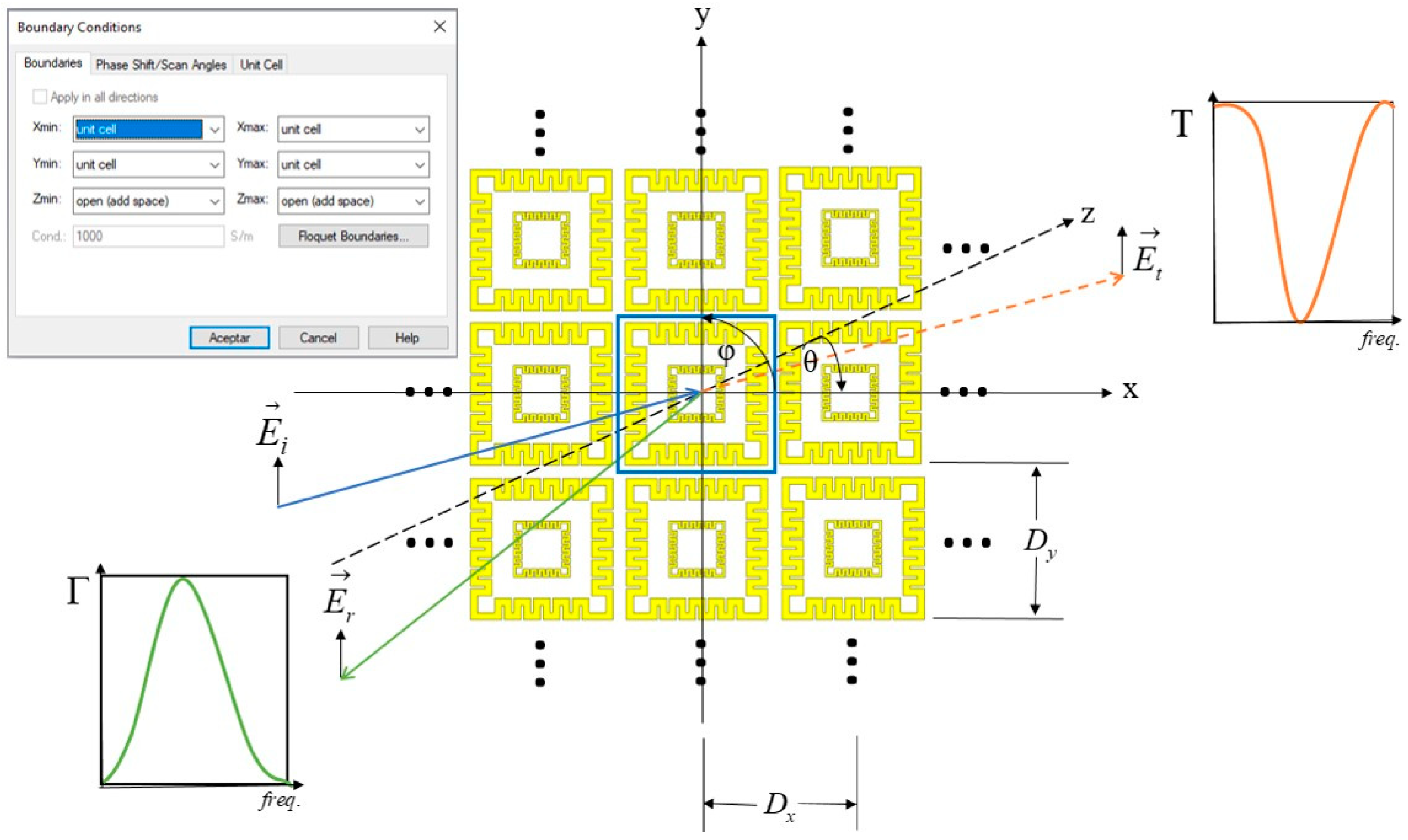
2.4. Analysis of Filtering Variation with Angle of Incidence

The influence of the inclination of the FSS structure is also studied in simulation, as shown in Figure 6. The structure is illuminated with a plane wave at normal incidence along the z-axis that changes from 0° to 60°.
Figure 6 reveals that the resonant frequency remains at 2 GHz, and the bandwidth is quite insensitive to variations of the incident angle theta from 0° to 60° on the horizontal xz plane (see coordinate system of Figure 3). However, the second frequency exhibits a change in response and proves to be sensitive to angle variation.

2.5. Low-Profile Implementation

The FSS structure was designed for the resonant frequencies of 2 GHz and 5.4 GHz with reduced inter-element spacing to achieve a low-profile design. Unfortunately, the unit cell simulation will not provide accurate results for practical 3 × 3 or 4 × 4 implementations, as explained below.
Figure 7 compares the transmission coefficient for the same FSS in simulation and measurement. The simulation corresponds to the FSS design with unit cell (infinite) boundary conditions, under the influence of mutual coupling (named FSSmc), due to close resonant elements with an inter-element spacing of 6 mm. The measurement corresponds to its implementation in a 4 × 4 array of the same resonator (named 4 × 4 FSSmc). As observed, there is a shift in the first expected frequency band. The reason for this is that each unit cell is surrounded by equal ones at all sides in the simulation, whereas, in the practical implementation, that only happens for the central cells. Working around this constraint would be convenient, taking advantage of the simplicity of unit cell simulation.
Figure 8 shows the impact of cell inter-element spacing on the transmission coefficient. As can be observed, the increase in inter-element spacing decreases mutual coupling impact until the first filtered band converges, regardless of the distance (no influence among cells). To illustrate the practical implication of this effect, a new 4 × 4 array of the same resonator is now implemented and compared to the unit cell simulation in the convergence point, that is, with 30 mm inter-element spacing (see Figure 9).
As expected, both simulation and measurement in their filtered bands agree. The target would be to match simulations and measurements, even if the mutual coupling between cells is present (shorter inter-element spacing, low-profile design). It could be argued that by scaling the design by a factor given by the ratio of the two resonant frequencies of the lower band in Figure 7 (simulated and measured), the new fabricated FSS would be brought back to the initial design frequency. Therefore, the problem would boil down to finding this ratio. In the following section, a method is proposed to extract this factor without measuring any prototypes.

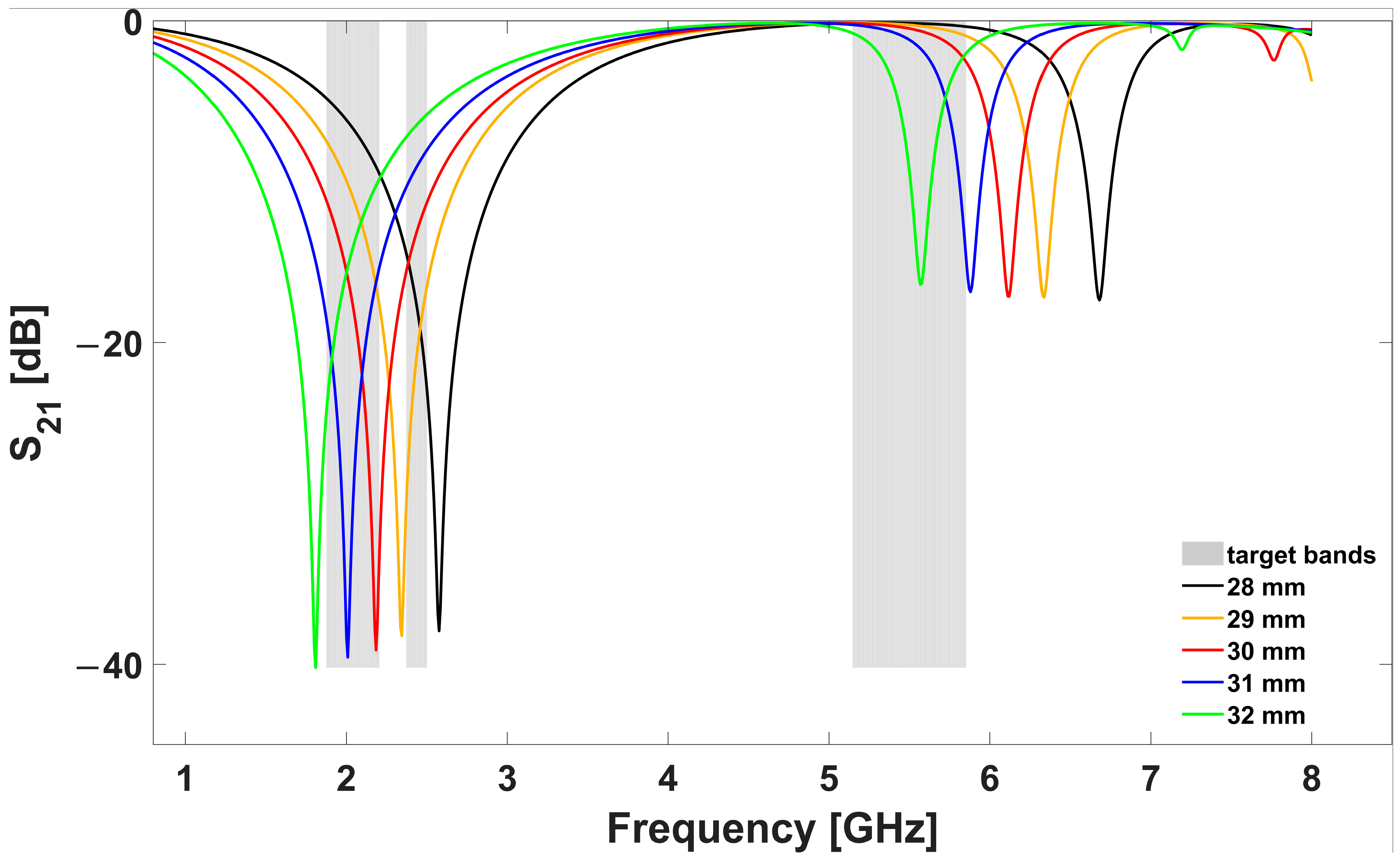
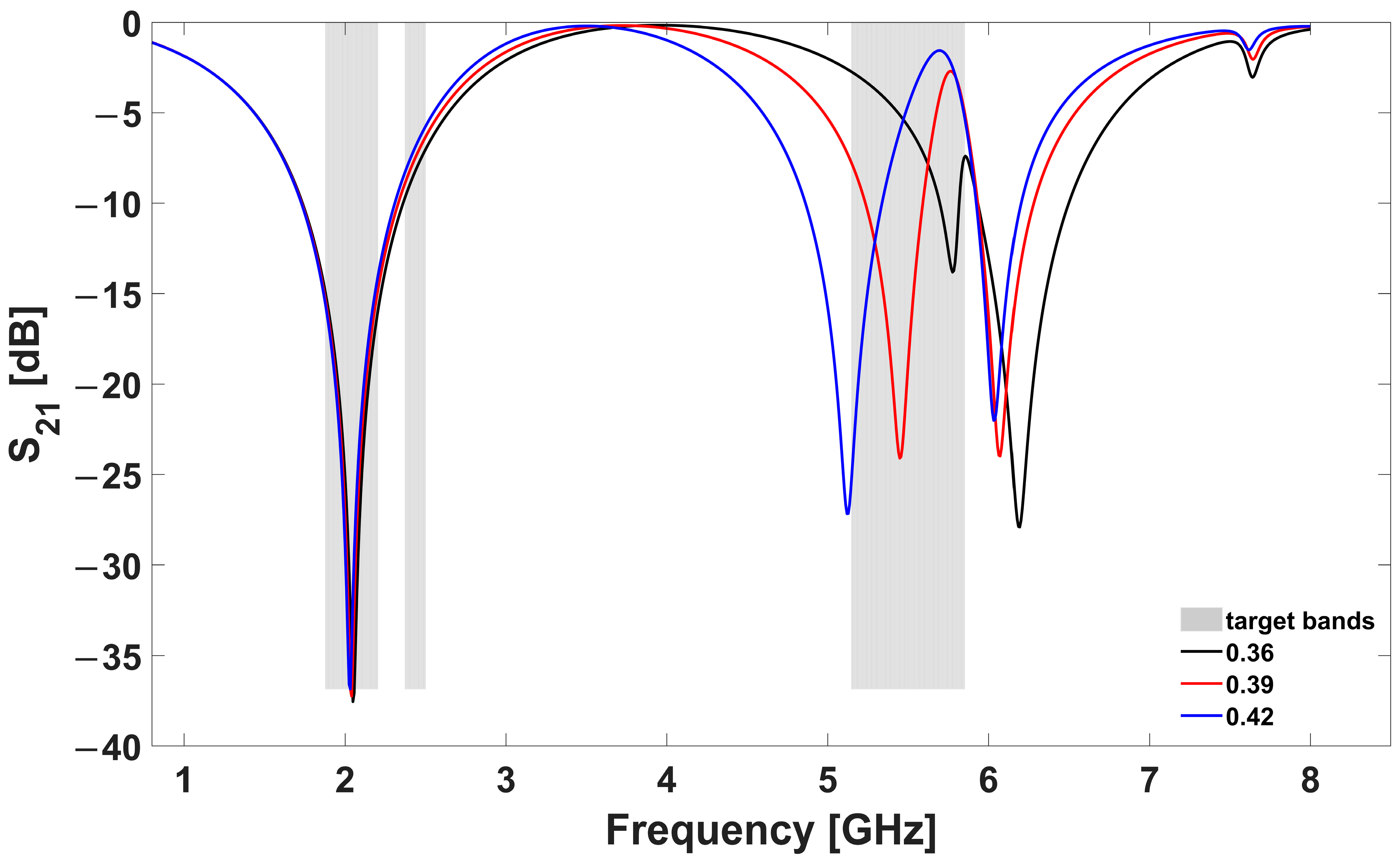
2.6. Proposed Strategy: Scale Factor Determination

Most of the cells in the practical implementation are surrounded mostly by air (except the fewer central ones in a 4 × 4 array). An important observation is that the 4 × 4 resonator with an inter-space of 6 mm has approximately the same response as the simulated result in the convergence point of Figure 8 for the first resonant frequency. Assuming this approximation, the scale factor could be inferred without fabricating a preliminary version to extract the disparity ratio by estimating it within the scope of pure simulation from Figure 8. Once the scale factor is applied to the original design, an equivalent resonator of larger dimensions will be obtained. When this new design is simulated under unit cell conditions, the expected resonant frequency should be lower than the measured one.
The scale factor α is defined as the quotient of the resonant frequency of the spaced FSS, which has no mutual coupling influence (f rnmc), divided by the resonant frequency of the unspaced FSS (f rmc) with mutual coupling effect.
α = f rnmc/f rmc
The unit cell dimensions will be scaled according to the ratio between the frequencies that were previously obtained. Only the internal resonator is left unchanged because its resonant frequency coincides with the band that is required to be attenuated. Comparative studies will be carried out to validate the scaling factor method proposed for the FSS design.
A summary of the proposed methodology for a low-profile FSS design is presented below:
  • FSSmc design with reduced inter-element spacing for a low-profile design at low frequencies.
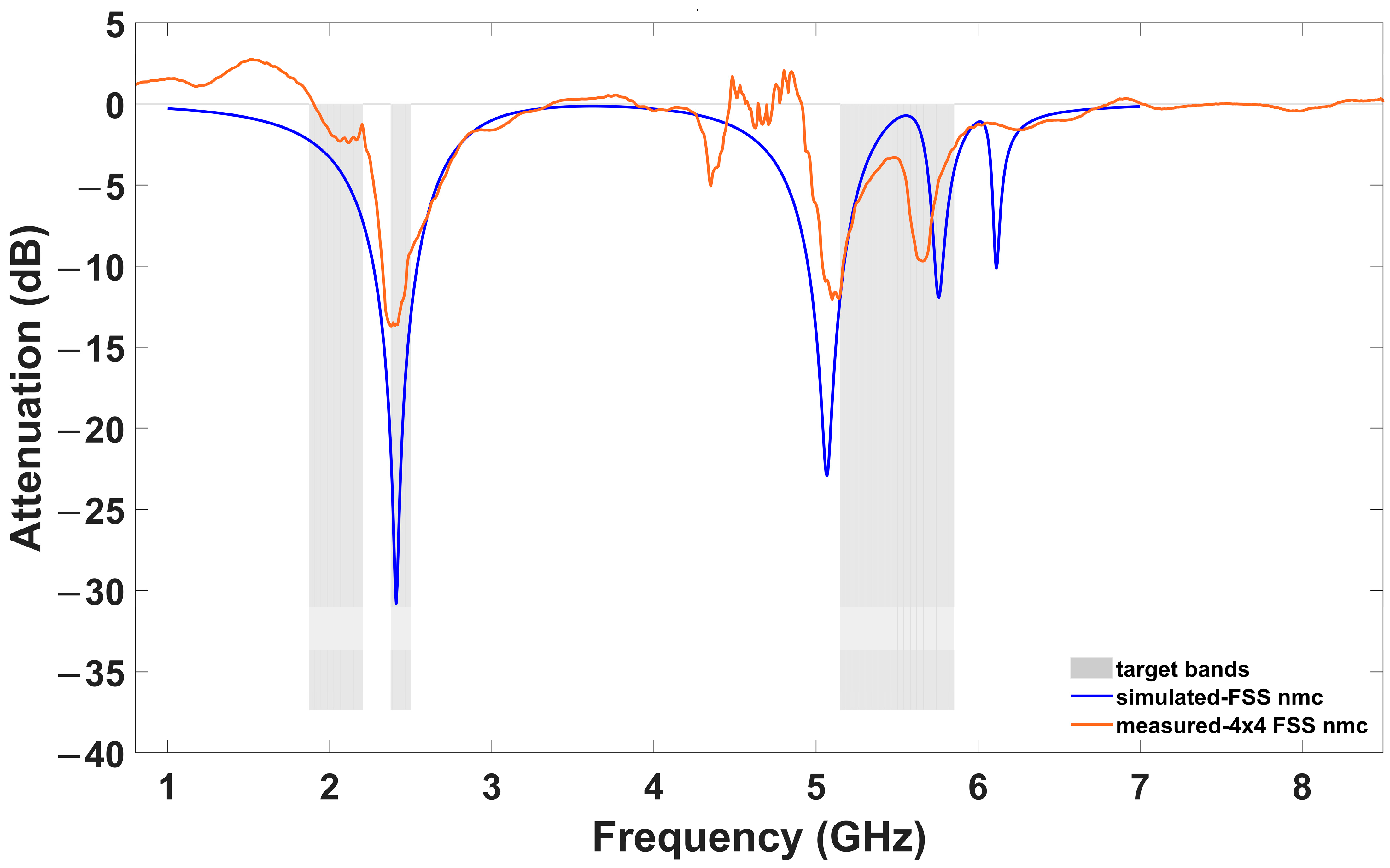
  • FSSnmc design = FSSmc design spaced until reaching convergence in the low-frequency bands (approximately λ/2 at the center of the filtered band).
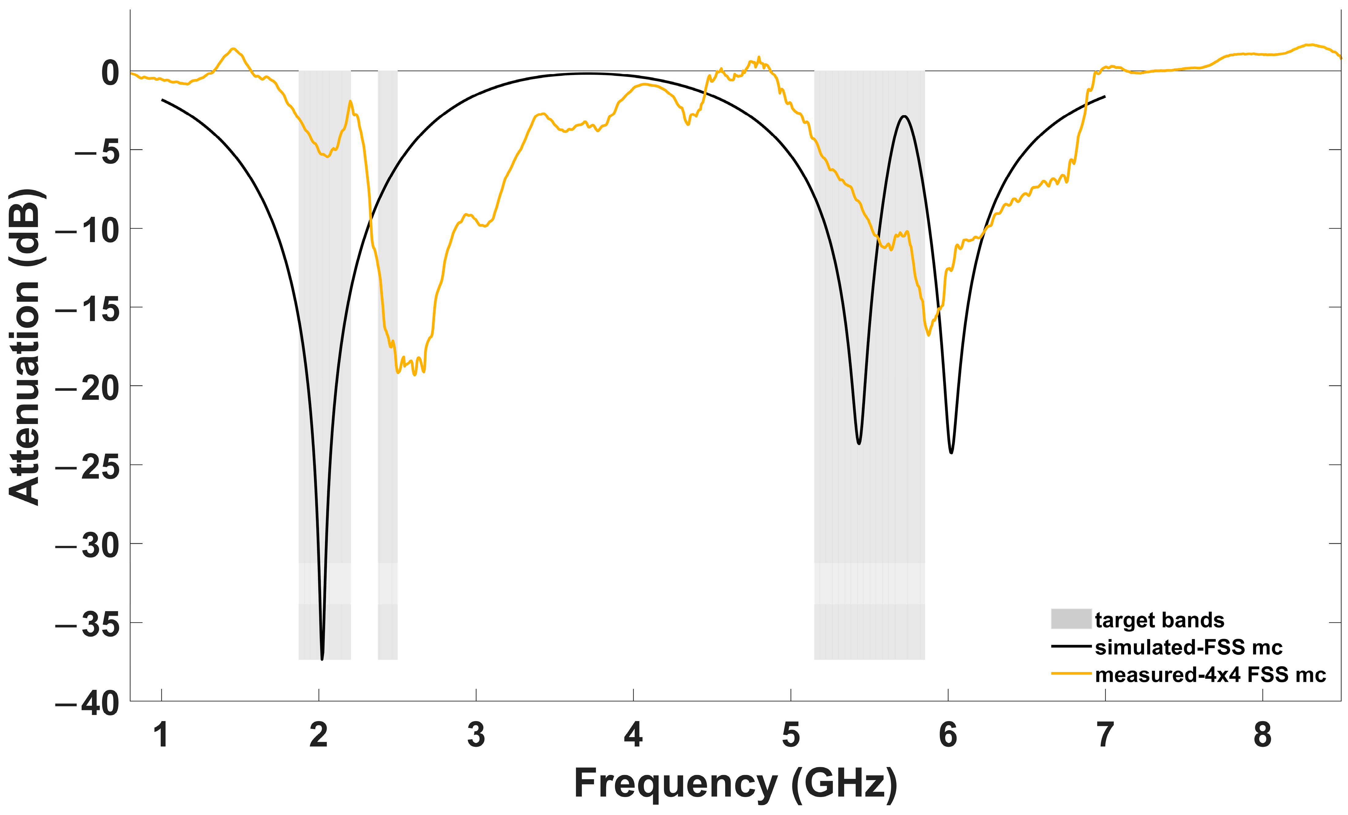
  • FSSscaled design = FSSmc design scaled by factor α leaving the inner resonator unchanged.
  • Fabricate FSSscaled design.
  • Measure FSSscaled design vs. Simulation FSSmc design.

3. Implementation and Results

The setup configuration consists of two aligned multifrequency antennas (Huber + Shuner Sencity Rail Antenna 1399.17.0122 [33]) on a metallic plane as a test bed for a train rooftop, separated by a distance of 1 m inside of an anechoic chamber (see Figure 10). The considered services of the railway rooftop antenna are mainly those included in Table 1. The FSS structure is fabricated on an FR-4 substrate of 0.8 mm thickness using conventional, low-cost printed circuit techniques. The attenuation achieved is obtained from the transmission parameter (S21) when the FSS structure is interposed between the antennas at a distance of 50 cm from each one.
The S21 parameter is measured with a vector network analyzer (VNA, Keysight E5071A). First, the transmission coefficient between the antennas is saved (memory), then the FSS is placed between the antennas (data) and the VNA data/memory option is applied, which allows to obtain the attenuation in dB normalized to the transmission without the FSS structure. For the measurements, the VNA was calibrated from 300 kHz to 8.5 GHz with 1601 points to achieve a high resolution.
It is important to highlight that we can obtain the scale factor (α = 1.2) from the previous simulations to adjust the resonant frequency without the need to fabricate neither FSSmc nor FSSnmc, as the main outcome of the design workflow. Only FSSscaled should be fabricated. This is performed in two sizes: 3 × 3 and 4 × 4, for final tuning and bandwidth analysis. The fabricated 4 × 4 prototype FSSscaled is presented in Figure 11, and Table 2 shows the unit cell dimensions, including the distance between the cells. The scale factor is applied only to the outer resonator in order to preserve the WiFi II band filtering as much as possible.
Figure 12 compares the simulated transmission coefficient of FSSmc and the measured 3 × 3 and 4 × 4 FSSscaled with a good agreement, particularly for the band for which the methodology was applied. The 4 × 4 FSSscaled achieves a maximum attenuation of 25 dB at 2 GHz but does not fully cover the rest of the target bands (grey vertical bands). The 3 × 3 FSSscaled covers all bands under 6 dB (dashed horizontal line). The 6 dB threshold level allows the reduction of half of the distance between antennas given by the Friis equation [34], with equal system performance. This is particularly helpful when space constraints are present in vehicular technology.
The study examined the inclination effect of the 3 × 3 FSSscaled design from theta (θ) = 0° to 45° on the horizontal plane. The findings presented in Figure 13 illustrate how the angle at which the FSS array is inclined affects the maximum attenuation that can be achieved in response to an incoming wave. It is worth noting that, despite the angle, the bandwidth remains relatively consistent in both frequency bands, achieving a 6 dB attenuation level. However, a noticeable decrease in attenuation is observed, particularly in the second frequency band. In addition, the achieved results exceed initial expectations when compared to the simulation results presented in Figure 6.
Finally, a comprehensive analysis comparing our proposed FSS isolating structure with related research is presented in Table 3, considering factors such as array size, isolation, operating frequency bands and other noteworthy features. Our design, despite its lower attenuation, exhibits numerous benefits, including compact size, straightforward construction, dual-band operation, cross-polarization capabilities in both horizontal and vertical planes and robust response across various inclinations.

4. Conclusions

The proposed approach provides a design methodology for a Meander Square Nested Resonator (MSNR) employed as a low-profile FSS band-stop filter placed between two vehicular antennas to avoid interferences. This methodology allows to simplify the workflow in the FSS design based on periodic boundaries, avoiding discrepancies with real implementations due to edge effects. This is accomplished using a scale factor derived from simulation. The proposed FSS design increases the isolation by 6 dB in three representative commercial bands of embarked multifrequency systems: 3GPP, WiFi I and WiFi II. This method can be easily extended to other bands. In this way, the distance between antennas can be reduced by an estimated factor of two, without decreasing performance. This solution is particularly attractive when dealing with frequent space constraints in vehicular antenna placement situations.

Author Contributions

Conceptualization, D.V. and J.I.S.; methodology, A.E., N.P. and J.I.S.; software, A.E. and J.I.S.; validation, A.E., N.P. and J.I.S.; formal analysis, A.E., N.P., D.V. and J.I.S.; investigation, A.E., N.P. and J.I.S.; resources, A.E. and J.I.S.; data curation, A.E.; writing—original draft preparation, A.E.; writing—review and editing, N.P., D.V. and J.I.S.; visualization, A.E.; supervision, N.P., D.V. and J.I.S.; project administration, D.V. and J.I.S.; funding acquisition, N.P., D.V. and J.I.S. All authors have read and agreed to the published version of the manuscript.

Funding

This work was supported by the ISOLAN project (ref: 2021-CIEN-000105-04-01) of the program “Red Guipuzcoana de Ciencia, Tecnología e Innovación of Diputación Foral de Gipuzkoa” and WINRES project (ref. PIBA 2021 1 0027) of the Basque Government PIBA program.

Institutional Review Board Statement

Not applicable.

Informed Consent Statement

Not applicable.

Data Availability Statement

Not applicable.

Acknowledgments

The authors appreciate the support of Contrucciones y Auxiliar de Ferrocarriles (CAF) for setting the specifications of the work. The authors thank the technicians Javier García and José Macayo (Tecnun School of Engineering, University of Navarra) for their work implementing the anechoic chamber.

Conflicts of Interest

The authors declare no conflict of interest.

References

  1. Guo, J.-Y.; Liu, F.; Jing, G.-D.; Zhao, L.-Y.; Yin, Y.-Z.; Huang, G.-L. Mutual coupling reduction of multiple antenna systems. Front. Inf. Technol. Electron. Eng. 2020, 21, 366–376. [Google Scholar] [CrossRef]
  2. Zhao, L.; Wu, K.L. A Dual-Band Coupled Resonator Decoupling Network for Two Coupled Antennas. IEEE Trans. Antennas Propag. 2015, 63, 2843–2850. [Google Scholar] [CrossRef]
  3. Jensen, M.A.; Wallace, J.W. A review of antennas and propagation for MIMO wireless commu-nications. IEEE Trans. Antennas Propag. 2004, 52, 2810–2824. [Google Scholar] [CrossRef] [Green Version]
  4. Gupta, N.; Ramesh, M. Method of improving isolation between co-located receive and transmit antennas in Portable Radars. In Proceedings of the 2018 IEEE MTT-S International Microwave and RF Conference (IMaRC), Kolkata, India, 28–30 November 2018; pp. 1–3. [Google Scholar] [CrossRef]
  5. X2Rail-3, Deliverable 3.4, Antenna System Specifications for Adaptable Communications in Railway Environment. Technical Report. 2023. Available online: https://projects.shift2rail.org/download.aspx?id=ce98d3c9-3c35-4c17-b9f9-d4f000c56d7a (accessed on 1 January 2023).
  6. RSSB, NR-GK/GN0602, Guidance on Train Rooftop Antenna Positioning. Technical Report. Available online: https://www.rssb.co.uk/standards-catalogue/CatalogueItem/GKGN0602-Iss-1 (accessed on 1 January 2023).
  7. Bakale, R.S.; Nandgaonkar, A.B.; Deosarkar, S.B. Isolation Enhancement Techniques for MIMO Antenna: A Review. In Proceedings of the 2020 International Conference on Smart Innovations in Design, Environment, Management, Planning and Computing (ICSIDEMPC), Aurangabad, India, 30–31 October 2020; pp. 57–62. [Google Scholar] [CrossRef]
  8. Kumar, S.; Dixit, A.S.; Malekar, R.R.; Raut, H.D.; Shevada, L.K. Fifth Generation Antennas: A Comprehensive Review of Design and Performance Enhancement Techniques. IEEE Access 2020, 8, 163568–163593. [Google Scholar] [CrossRef]
  9. Nath, R.; Singh, P. Review on Isolation Techniques in MIMO Antenna Systems. Int. J. Adv. Res. Sci. Eng. 2018, 7, 600–611. [Google Scholar] [CrossRef]
  10. Mano Janat, T.R.; Astuti, R.P.; Nugroho, B.S. The Effect of Implementing Resonator-Interdigital Capacitor and Complementary Split Ring Resonator (CSRR) on MIMO Antenna. In Proceedings of the 2019 IEEE/CVF Conference on Computer Vision and Pattern Recognition (CVPR), Long Beach, CA, USA, 15–20 June 2019; pp. 23–27. [Google Scholar] [CrossRef]
  11. Chen, L.; Zhang, T.; Zaman, A.U.; Yang, J. A Method of Reducing Mutual Coupling for a Finite Array. In Proceedings of the 14th European Conference on Antennas and Propagation (EuCAP), Copenhagen, Denmark, 15–20 March 2020; pp. 1–3. [Google Scholar] [CrossRef]
  12. Bhatti, R.A.; Yi, S.; Park, S.O. Compact Antenna Array With Port Decoupling for LTE-Standardized Mobile Phones. IEEE Antennas Wirel. Propag. Lett. 2009, 8, 1430–1433. [Google Scholar] [CrossRef]
  13. Cheng, Y.F.; Cheng, K.K.M. Compact Wideband Decoupling and Matching Network Design for Dual-Antenna Array. IEEE Antennas Wirel. Propag. Lett. 2020, 19, 791–795. [Google Scholar] [CrossRef]
  14. Srivastava, N.; Rao, P.K.; Mishra, R. Decoupling Function for UWB MIMO Antenna to Enhance Bandwidth with Neutralization Line. In Proceedings of the 2019 IEEE 5th International Conference for Convergence in Technology (I2CT), Bombay, India, 29–31 March 2019; pp. 1–3. [Google Scholar] [CrossRef]
  15. Zhang, L.; Zhang, S.; Song, Z.; Liu, Y.; Ye, L.; Liu, Q.H. Adaptive Decoupling Using Tunable Metamaterials. IEEE Trans. Microw. Theory Tech. 2016, 64, 2730–2739. [Google Scholar] [CrossRef]
  16. Niu, Z.; Zhang, H.; Chen, Q.; Zhong, T. Isolation Enhancement for 1 × 3 Closely Spaced E-Plane Patch Antenna Array Using Defect Ground Structure and Metal-Vias. IEEE Access 2019, 7, 119375–119383. [Google Scholar] [CrossRef]
  17. Ding, C.F.; Zhang, X.Y.; Xue, C.D.; Sim, C.Y.D. Novel Pattern-Diversity-Based Decoupling Method and Its Application to Multielement MIMO Antenna. IEEE Trans. Antennas Propag. 2018, 66, 4976–4985. [Google Scholar] [CrossRef]
  18. Alibakhshikenari, M.; Vittori, M.; Colangeli, S.; Virdee, B.S.; Andújar, A.; Anguera, J.; Limiti, E. EM isolation enhancement based on metamaterial concept in antenna array system to support full-duplex application. In Proceedings of the 2017 IEEE Asia Pacific Microwave Conference (APMC), Kuala Lumpur, Malaysia, 13–16 November 2017; pp. 740–742. [Google Scholar] [CrossRef]
  19. Tan, X.; Wang, W.; Wu, Y.; Liu, Y.; Kishk, A.A. Enhancing Isolation in Dual-Band Meander-Line Multiple Antenna by Employing Split EBG Structure. IEEE Trans. Antennas Propag. 2019, 67, 2769–2774. [Google Scholar] [CrossRef]
  20. Woo, D.W.; Kim, J.H.; Ji, J.K.; Kim, G.H.; Seong, W.M.; Park, W.S. Design of a DSRR FSS for CDMA/RFID isolation. In Proceedings of the 2010 IEEE Antennas and Propagation Society International Symposium, Toronto, ON, Canada, 11–17 July 2010; pp. 1–4. [Google Scholar] [CrossRef]
  21. Merzaki, F.; Sergolle, M.; Castel, X.; Himdi, M.; Besnier, P.; Desmars, K.; Levavasseur, T.; Caldamone, P.; Parneix, P. A Compact Absorbing FSS Structure for Antenna Decoupling in the 5G 3.5GHz Band. In Proceedings of the 2020 International Symposium on Electromagnetic Compatibility-EMC EUROPE, Rome, Italy, 23–25 September 2020; pp. 1–6. [Google Scholar] [CrossRef]
  22. Ketzaki, D.A.; Ntaikos, D.K.; Bourgis, N.K.; Yioultsis, T.V. Metamaterial-Enhanced MIMO Antennas 2015. pp. 1–4. Available online: https://www.researchgate.net/publication/267244073_Metamaterial-enhanced_MIMO_Antennas (accessed on 1 January 2023).
  23. Wang, X.; Che, W.; Yang, W.; Feng, W.; Gu, L. Self-Interference Cancellation Antenna Using Auxiliary Port Reflection for Full-Duplex Application. IEEE Antennas Wirel. Propag. Lett. 2017, 16, 2873–2876. [Google Scholar] [CrossRef]
  24. Xiao, Y.; Wang, Y. Deep Learning-Based Mutual Coupling Modeling and Baseband De-coupling Algorithm for MIMO Systems. IEEE Commun. Lett. 2020, 24, 1986–1990. [Google Scholar] [CrossRef]
  25. Anwar, R.S.; Mao, L.; Ning, H. Frequency selective surfaces: A review. Appl. Sci. 2018, 8, 1689. [Google Scholar] [CrossRef] [Green Version]
  26. Zhu, Y.; Chen, Y.; Yang, S. Decoupling and Low-Profile Design of Dual-Band Dual-Polarized Base Station Antennas Using Frequency-Selective Surface. IEEE Trans. Antennas Propag. 2019, 67, 5272–5281. [Google Scholar] [CrossRef]
  27. De Sabata, A.; Matekovits, L.; Buta, A.; Dassano, G.; Silaghi, A. Frequency Selective Surface for Ultra-Wide Band Filtering and Shielding. Sensors 2022, 22, 1896. [Google Scholar] [CrossRef] [PubMed]
  28. Munk, B.A. Frequency Selective Surfaces: Theory and Design; John Wiley & Sons, Inc.: New York, NY, USA, 2000; pp. 1–70. [Google Scholar] [CrossRef]
  29. Fang, C.; Wang, Q.; Zhang, N.; Jiang, H.; Zhang, Y.; Bai, M.; Ye, X. Investigation of the RCS for a finite bandpass frequency selective surface. In Proceedings of the 2018 International Applied Computational Electromagnetics Society Symposium-China (ACES), Beijing, China, 29 July–1 August 2018; pp. 1–2. [Google Scholar] [CrossRef]
  30. Zhang, H.; Zhong, T. Miniaturized frequency selective surface based on 2.5-dimensional closed spiral loops with stable resonant frequency. In Proceedings of the 2017 IEEE Conference on Computer Vision and Pattern Recognition (CVPR), Honolulu, HI, USA, 21–26 July 2017; pp. 1–3. [Google Scholar] [CrossRef]
  31. Li, G.J.; Luan, H.S.; Peng, H.L.; Wang, J. A new Hilbert structure based meta-surface for improving isolation between two antenna elements. In Proceedings of the 2017 IEEE Electrical Design of Advanced Packaging and Systems Symposium (EDAPS), Haining, China, 14–16 December 2017; pp. 1–3. [Google Scholar]
  32. Saou-Wen Su, C.T.L.; Hsiao, Y.W. Compact Two-Inverted-F-Antenna System With Highly Integrated-Shaped Decoupling Structure. IEEE Trans. Antennas Propag. 2019, 67, 6182–6186. [Google Scholar] [CrossRef]
  33. HUBER+SUHNER 1399.17.0122 DataSheet. Available online: https://ecatalog.hubersuhner.com/product/E-Catalog/Radio-frequency/Antennas-accessories/Antennas/84071876/1399.17.0122 (accessed on 1 September 2022).
  34. Balanis, C.A. Antenna Theory: Analysis and Design, 2nd ed.; John Wiley & Sons, Inc.: New York, NY, USA, 1997. [Google Scholar]
Figure 2. Meander-line nested square structure dimensions.
Applsci 13 04187 g002
Figure 3. FSS structure excited by an incident plane wave (Ei), which is reflected (Er) and transmitted (Et).
Applsci 13 04187 g003
Figure 4. Simulated effect of increasing square length (Lq sweep parameter).
Applsci 13 04187 g004
Figure 5. Simulated effect of the inner resonator.
Applsci 13 04187 g005
Figure 6. Simulated effect of increasing the inclination angle theta (θ) from 0° to 60°.
Applsci 13 04187 g006
Figure 7. Floquet mode simulation vs. measure of the unspaced 4 × 4 FSS design for antenna isolation.
Applsci 13 04187 g007
Figure 8. Simulated effect of increasing inter-element spacing (d) under Floquet mode boundary conditions.
Applsci 13 04187 g008
Figure 9. Floquet mode simulation vs. measurement of the spaced FSS design (30 mm inter-element spacing).
Applsci 13 04187 g009
Figure 10. Experimental setup for the FSS structure measurement in an anechoic chamber.
Applsci 13 04187 g010
Figure 11. FSSscaled prototype.
Applsci 13 04187 g011
Figure 12. Comparison of simulated FSSmc (unit cell boundary condition) and measured FSSscaled.
Applsci 13 04187 g012
Figure 13. Comparison of measured FSSscaled for different angle (θ).
Applsci 13 04187 g013
Table 1. Services and Frequency Bands.
ServiceFreq. Band (MHz)
3GPP1875–2200
WiFi I2375–2500
WiFi II5150–5850
Table 2. Unit cell dimensions of the FSSscaled prototype.
4 × 4 FSSscaledDimensions (mm)
Ls42
hs0.8
w1.5
Lq34.8
Lt9.24
Lg1.2
Ld3.6
s9.12
d7.2
Table 3. Compilation of the proposed FSS with relevant works.
Unit Cell DesignFSS SizeIsolationBandwidthRemarksRef.
Interdigitated4.1λ × 4.1λ12 dB3.2–3.7 GHzsingle band operation, narrow bandwidth, composite low-loss substrate, complex design[21]
Square ring3.5λ × 3.5λ20 dB3.5–4.9 GHzsingle band attenuation, cross-polarization discrimination (XPD > 20 dB)[26]
Two-layer Double Split Ring Resonator (DSRR)1.058λ × 1.058λ30 dB915 MHznarrow bandwidth, mismatch between simulation and measurement[20]
Square single loop0.58λ × 0.316λ20 dB0.6–1.4 GHzsingle band operation, double side FSS structure, simple design[4]
Meander Square Nested Resonator (MSNR)2.31λ × 2.31λ6 dB1.875–2.5 GHz and 5.15–5.85 GHzcompact size, dual-band operation, dual-polarization, stable to angle influence[this work]
Disclaimer/Publisher’s Note: The statements, opinions and data contained in all publications are solely those of the individual author(s) and contributor(s) and not of MDPI and/or the editor(s). MDPI and/or the editor(s) disclaim responsibility for any injury to people or property resulting from any ideas, methods, instructions or products referred to in the content.

