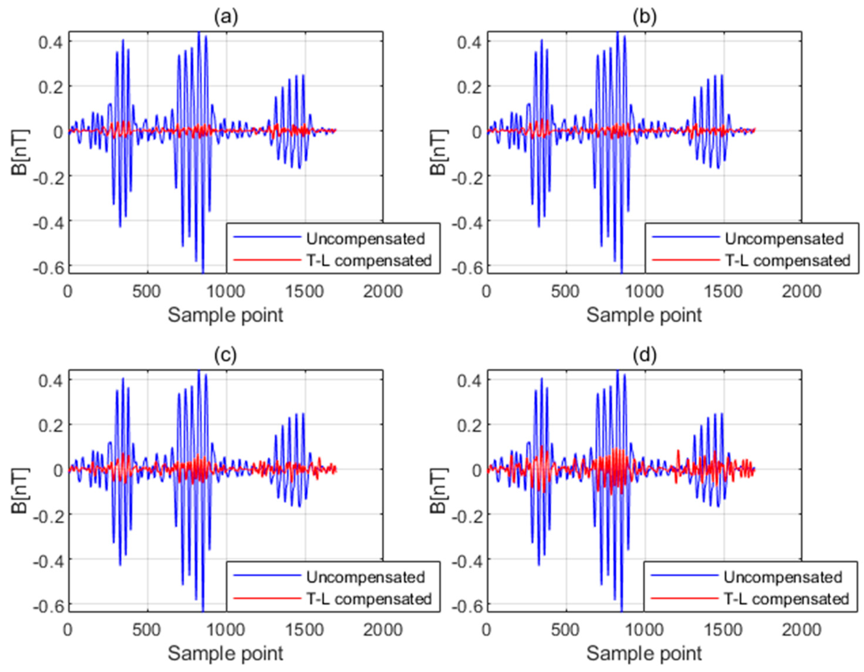
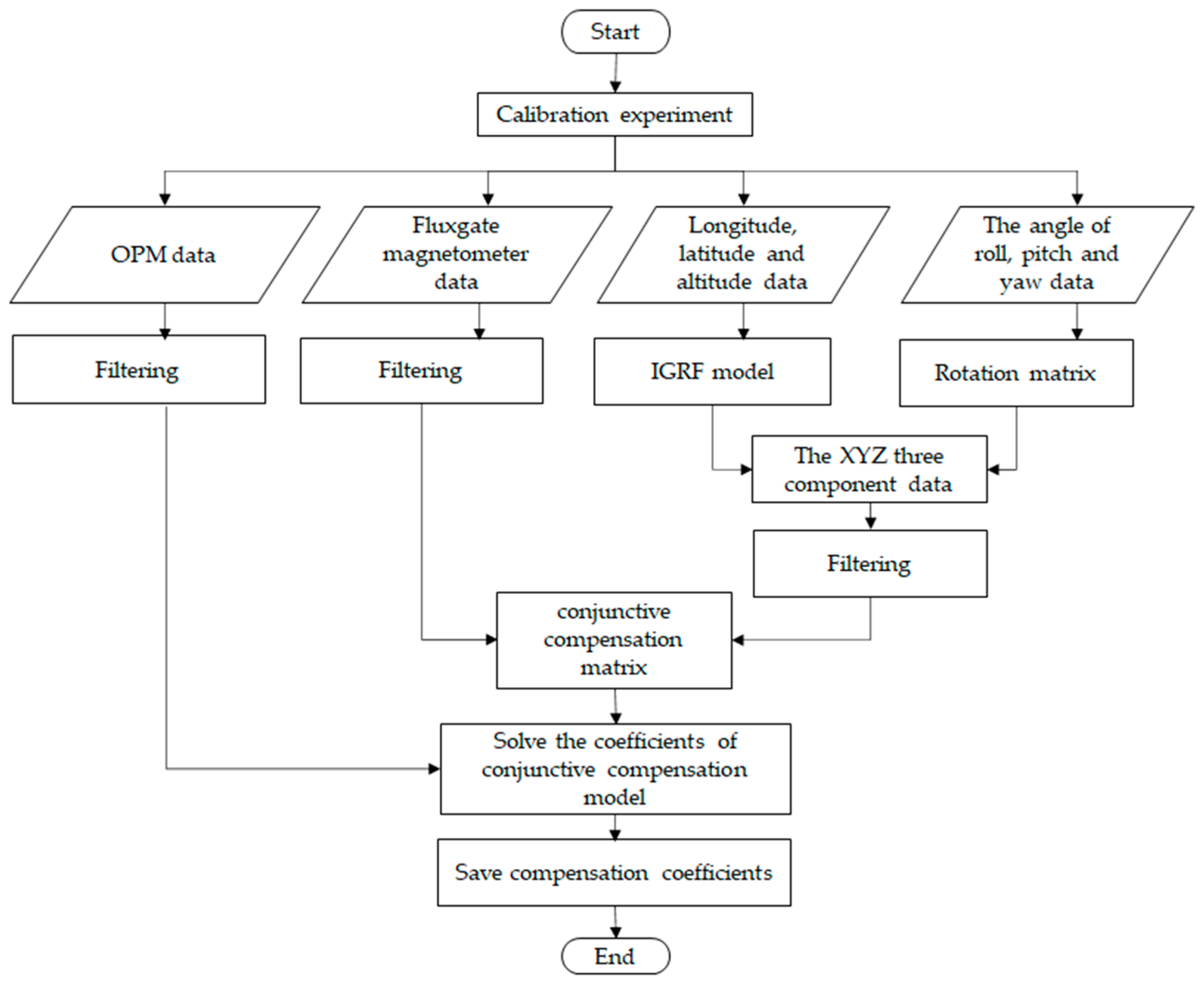
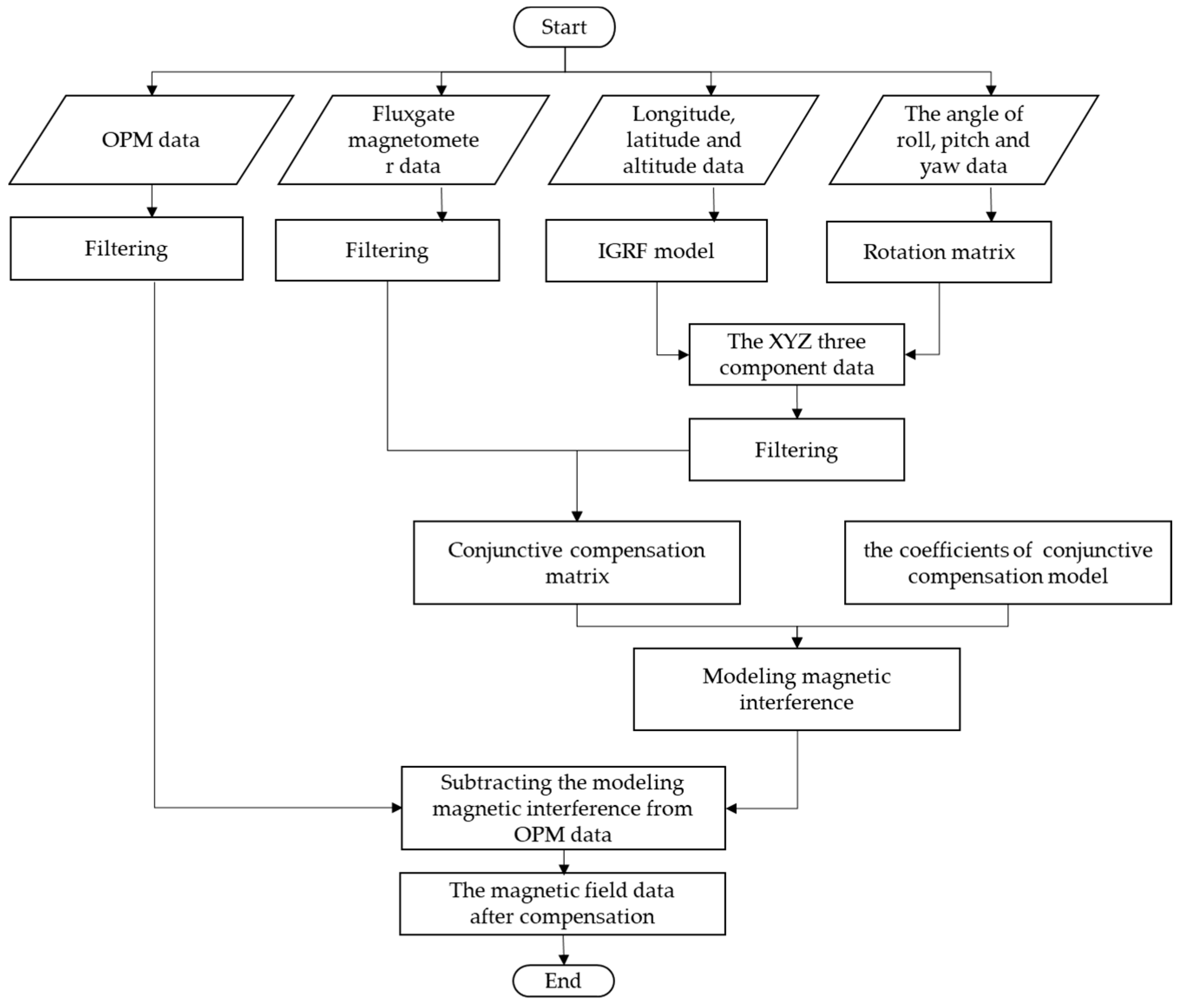
We proposed a new conjunctive compensation method based on INS/GPS and fluxgate magnetometer information. The classical compensation method uses a fluxgate magnetometer to obtain the three components of the geomagnetic field in the body coordinate system to construct the attitude matrix. According to the T-L model, as long as the change in three components of the geomagnetic field in the aircraft coordinate system due to aircraft action can be described, the attitude matrix can be constructed to compensate. So, it is possible to construct an attitude matrix by transforming some auxiliary information that INS/GPS provides.
3.1. Compensation Principle
As a magnetic field sensor, the magnetic field measured by the fluxgate is susceptible to interference from external magnetic fields. Meanwhile, the fluxgate itself has the problem of diversionary error, which leads to errors in attitude information obtained by fluxgate measurement during flight. INS is not affected by the magnetic field, but the accuracy is not high. By introducing INS information into the T-L model, attitude information from fluxgate and INS can complement each other to make up for the deficiency of a single sensor.
According to the T-L model, we need to describe the change in three components of the geomagnetic field in the aircraft coordinate system due to aircraft action.
The international geomagnetic reference field (IGRF) is a general international model for describing the earth’s main magnetic field through using the longitude, latitude, and altitude information [
22]. At present, this model can be used to calculate the seven elements of the geomagnetic field at any point. So, according to the IGRF model, the geomagnetic field parameters (geomagnetic field inclination I, geomagnetic field declination D, and geomagnetic field intensity
) in the geodetic coordinate system can be calculated by using the longitude, latitude, and altitude information in the aircraft GPS [
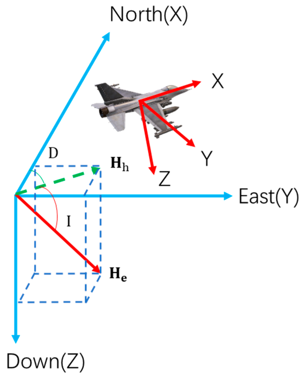
23]. The aircraft coordinate system can change with the change in roll angle, pitch angle, and heading angle, so it is necessary to convert the geomagnetic field in the geodetic coordinate system to the geomagnetic field in the aircraft coordinate system, as shown in
Figure 2.
For description, this paper defines the geodetic coordinate system and the aircraft coordinate system as follows:
Geodetic coordinate system: the north-east geodetic coordinate system, with the X-axis pointing to geographic north, the Y-axis pointing to geodetic east, and the Z-axis pointing to the earth’s center. denotes the geomagnetic field, denotes the horizontal component of the geomagnetic field, and D and I denote the geomagnetic declination and geomagnetic inclination, respectively.
Aircraft coordinate system: a rectangular coordinate system fixed on an aircraft with the origin at the aircraft’s center. The X-axis is parallel to the fuselage axis and points to the flying head. The Y-axis is perpendicular to the longitudinal section of the fuselage and points to the right wings. The Z-axis is perpendicular to the plane where the fuselage is located and points to the bottom of the aircraft. The angle of roll, pitch, and yaw are θ, φ, and ψ, respectively.
According to the IGRF model, the geomagnetic field parameters can be calculated by Equation (16).
The XYZ three components of the geomagnetic field in the geodetic coordinate system are shown in the following equations:
The XYZ three components of geomagnetic field vector in the aircraft coordinate system are set to (
,
, and
). The XYZ three components of the geomagnetic field vector in the geodetic coordinate system are set to (
,
, and
). The angle of roll, pitch, and yaw can directly be obtained by INS. According to the three-dimensional rotation matrix [
24], the XYZ three components of the geomagnetic field in the aircraft coordinate system are expressed as follows:
So, we can obtain the change in three components of the geomagnetic field in the aircraft coordinate system due to aircraft action without fluxgate magnetometer data. The T-L compensation model based on fluxgate magnetometer information is expanded and we establish a conjunctive compensation model with 36 coefficients. The expression is as follows:
where
,
, and
are the compensation coefficients based on fluxgate magnetometer information, and
is the cosine of the angle between the geomagnetic field and the three axes of aircraft coordinate system and it can be calculated using the measured values
,
i = 1, 2, 3 of the three axes of the fluxgate magnetometer. The expression is (25)and
is the time derivative of
.
can be calculated by Equation (26).
are the compensation coefficients based on INS/GPS information, and
is the cosine of the angle between the geomagnetic field and the three axes of the aircraft coordinate system calculated by the IGRF and the rotation matrix and it is calculated using the analog values
, i = 1, 2, 3 by the IGRF and rotation matrix. The expression is (27) and
is the time derivative of
.
can be calculated by Equation (28).
So, the matrix form of Equation (22) can be expressed as follows:
where
is n × 36 platform attitude matrix and
is 36 × 1 coefficients matrix.
Then, the least squares solution of the compensation coefficient
can be expressed as follows:


