Article

Design of an Intelligent Cascade Control Scheme Using a Hybrid Adaptive Neuro-Fuzzy PID Controller for the Suppression of Drill String Torsional Vibration

by
Abdelbaset Laib
1,2 and
Mohamed Gharib
1,3,*
1
Department of Mechanical Engineering, Texas A&M University at Qatar, Doha 23874, Qatar
2
Department of Automatic, Faculty of Electrical Engineering, University of Science & Technology Houari Boumediene, Bab Ezzouar 16111, Algeria
3
Department of Engineering Technology & Industrial Distribution, Texas A&M University, College Station, TX 77843, USA
*
Author to whom correspondence should be addressed.
Appl. Sci. 2024, 14(12), 5225; https://doi.org/10.3390/app14125225
Submission received: 15 May 2024 / Revised: 2 June 2024 / Accepted: 10 June 2024 / Published: 16 June 2024
(This article belongs to the Section Acoustics and Vibrations)

Abstract

:
Eliminating the excessive stick–slip torsional vibrations of drill strings by utilizing an effective controller can significantly increase penetration rates and reduce drilling operation costs. The present study aims to develop a fast and intelligent cascade control structure for a multi-degree-of-freedom drill string system under torsional vibrations. The proposed control configuration consists of two control loops in a cascade arrangement. The first controller estimates the top drive velocity reference from the actual drill bit velocity and its reference. The role of the second controller is to regulate the top drive velocity to its reference by generating the necessary torque for the drilling operation process to progress. Each control loop is designed based on a hybrid adaptive neuro-fuzzy PID and feedforward term. The latter assures fast regulation when there are sudden changes in operation. To evaluate the performance of the suggested cascade feedforward neuro-fuzzy PID (CFF-NFPID) control structure, extensive simulations were conducted using Matlab/Simulink. The simulation results clearly showed that the proposed CFF-NFPID controller provided high-performance control with variations in the weight on the bit and the desired drill bit rotary speed in comparison with that of cascade feedforward fuzzy PID, sliding-mode, cascade feedforward PID, cascade PID, and conventional PID controllers. Furthermore, the control robustness is very suitable despite the change in the system parameters.

1. Introduction

The control of drill string systems in oil wells to improve extraction has received significant attention in the gas and petroleum industry. A drill string is composed of a rotary table, a series of hollow drill pipes, and a bottom hole assembly (BHA). Numerous drill collars and intermediate stabilizers connecting to a drill bit are the main components of a BHA [1,2]. The rotary table provides the required torque on the bit (TOB) to the bottom of the borehole through the components of the drill string system [3,4]. A drill string system is regarded as a complex dynamic system with many indefinite and unstable parameters due to the changes in the characteristics of a drill string that occur during drilling operations. Furthermore, different challenges within the perforation process can lead to failure or an elevation of its overall cost. The interaction between the drill string and the borehole causes many undesired vibrations. Therefore, these vibrations are the most common cause of perforation process failure [4,5]. A permanently stuck bit, which occurs in cases where the bit is unable to rotate, is the most detrimental phenomenon aside from stick–slip at the bit. The stick–slip phenomenon occurs when the top rotary table system maintains a constant rotary speed while the bit’s rotary speed fluctuates between zero and several times the surface rotary speed [1,2,3,4,5]. Many researchers have suggested various passive control methods for mitigating these undesirable phenomena. The most common passive control approaches discussed in the literature include drill string reconfiguration, bit selection with redesign, optimization of the BHA configuration, and the use of anti-vibration down hole tools [3]. These approaches prevent stick–slip vibrations by changing the weight on the bit (WOB) and/or the bit velocity. However, the effectiveness of these approaches is not perfect under all conditions [3,4,5]. As an example of passive approaches, the authors of [6] introduced a zone with optimal operating conditions that ensured the stability of a drill string system during its operation. The zones bordering the optimal zone underwent stick–slip phenomena, backward whirls, forward whirls, and a low rate of penetration (ROP). Nevertheless, these zones are likely to disappear entirely when drilling into hard formations. Therefore, the control of vibration in drill string systems based on the adjustment of the drilling parameters typically fails, which leads to the degradation of the effectiveness of passive control approaches [3,4,5].
Because of the improvements in real-time measurement, different closed-loop control strategies have been designed and applied. Initially, a control scheme based on a proportional–integral (PI) regulator was created and implemented in [7,8]. A cascade control scheme was designed in [9] to improve the performance provided by conventional control schemes. In [10], Christoforou and Yigit proposed an optimum state feedback control mechanism to regulate a drill string’s rotational motion. To limit stick–slip vibrations, Serrarens et al. developed a linear  H  control strategy [11]. Moreover, in [12], a linear quadratic controller was designed through a linearized model of a drill string. The previous active controllers were considered linear control methods. The performance of this type of controller is limited due to the high nonlinearity of drill string systems. By taking the modeling errors in the control design process in terms of uncertain WOB into consideration, Vermon et al. developed synthesis control strategy for drill string systems [13]. The design of this control strategy requires the linearization of the dynamic model of the drill string system around an operating point. Therefore, the functionality of the controller cannot be confirmed, especially in the case of more degrees of freedom (DOFs).
To avoid the limitations of linear control schemes, in [14], Al-Hiddabi et al. investigated a nonlinear dynamic inversion control method. The main objective of this method was to suppress lateral and torsional vibrations. In [15], Navarro-Lopez and Liceaga-Castro introduced the dynamic sliding-mode theory to design an effective controller (SMC) that avoided different bit-sticking problems. Yang Liu modified the SMC to achieve a tolerance for parameter uncertainties and robustness to variations in the WOB [16]. Nevertheless, the design of nonlinear control schemes is based on a system model in addition to much information about the system, which degrades the control performance.
Recently, artificial intelligence techniques have been increasingly utilized in industrial control applications due to the rapid advancement of signal processing capabilities and the progression of industrial informatics [17,18,19,20,21,22,23,24,25,26]. The ability to develop effective control schemes without depending on a mathematical model of the considered system is a key benefit of artificial intelligence. Fuzzy logic control (FLC) [17,18,19,20,21], artificial neural networks (ANNs) [22,23], and adaptive neuro-fuzzy inference systems (ANFISs) [24,25,26] have been widely employed in the literature to develop intelligent controllers. These techniques are appropriate for developing robust regulators of unknown or uncertain systems. Laib et al. designed an optimal hybrid interval Type-2 fuzzy PID+I logic controller (OH-IT2FPID+I) using a practical swarm optimization algorithm for a multi-degree-of-freedom oil well drill string system [27]. The proposed OH-IT2FPID+I provided high control performance under several critical conditions. However, the FLC’s efficacy was restricted, since it depended on expert knowledge to determine the controller’s optimal gains. For these reasons, ANFISs have recently been employed instead of FLC to improve control performance because they provide more DOFs to deal with nonlinearities [24,25,26]. ANFIS is a type of ANN that exploits the learning ability of neural networks with the performance of fuzzy linguistics [26]. On the other hand, numerous researchers have attempted to combine FLC with conventional PID control to enhance the control performance [28,29,30].
To improve the control performance for multi-DOF oil well drill string systems and eliminate stick–slip phenomena, a cascade control scheme for drill string systems was investigated and modified using hybrid neuro-fuzzy PID and feedforward terms (CFF-NFPID). The suggested control configuration involved two control loops. The first controller estimated the top drive velocity reference from the drill bit velocity and its reference. The second controller aimed to regulate the top drive velocity to its reference by generating the required torque. Each control loop was designed based on hybrid adaptive neuro-fuzzy PID and feedforward terms. Adaptive neuro-fuzzy control was combined with conventional PID control to develop a hybrid neuro-fuzzy PID control scheme (H-NFPID). Furthermore, a feedforward term for each control loop was designed based on a mathematical model of a multi-DOF oil well drill string system. The main objective of the proposed CFF-NFPID was to regulate the rotary velocities of the drill string components—especially the rotary table velocity and drill bit velocity—to a desired value in order to overcome several bit-sticking problems and stick–slip vibration. The proposed control structure was evaluated and tested through numerical simulations in Matlab/Simulink with variations in the WOB, the desired drill bit rotary speed, and parametric uncertainties. Furthermore, the performance of the CFF-NFPID controller was quantitatively compared with that of a cascade feedforward fuzzy PID (CFF-FPID) controller, a cascade feedforward PID (CFF-PID) controller, two SMC algorithms, a cascade PID (C-PID) controller, and a conventional PID controller.
The remainder of this article is structured as follows: In Section 2, a discontinuous torsional model for a drill string, which includes bit–rock interactions, is discussed. The modified cascade control structure based on a hybrid neuro-fuzzy PID control structure and feedforward terms is presented in Section 3. This section consists of two parts. The first part discusses the hybrid neuro-fuzzy PID for each control loop, while the second part presents a mathematical demonstration of the suggested feedforward terms. The simulation results are illustrated and analyzed in Section 4. Finally, the main conclusions of the work are drawn and are followed by references.

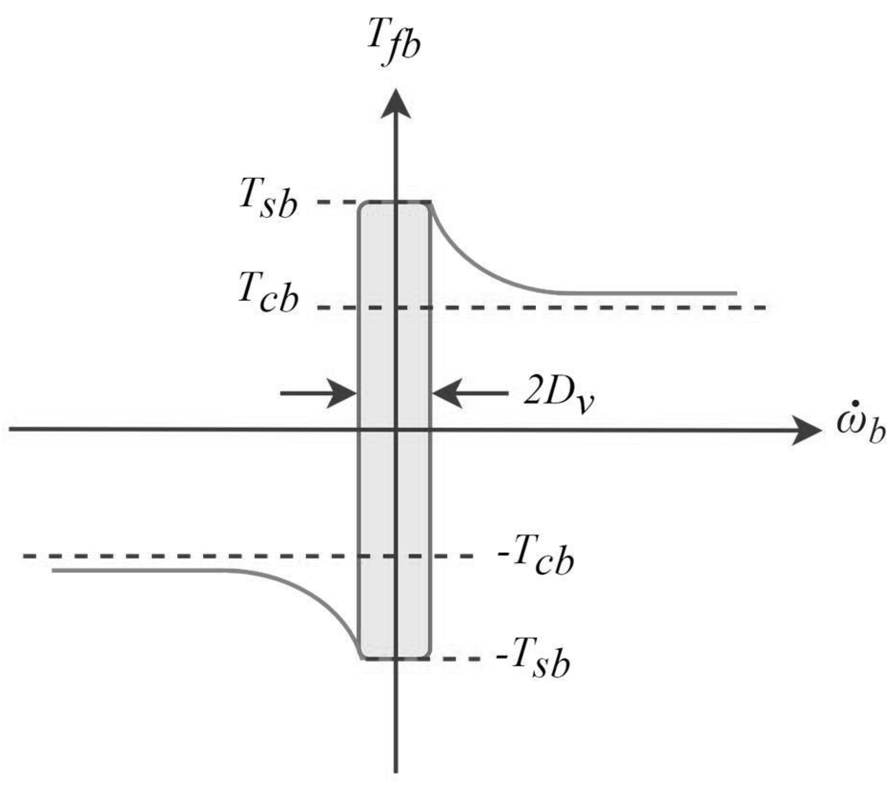
2. The Mathematical Model of a Drill String System

In the last few years, numerous studies have focused on describing physical phenomena in actual boreholes in order to develop an accurate dynamic mathematical model for drill string systems [31]. The preferred dynamic model for designing active control strategies is called the lumped parameter model. In this mathematical model, a drill string system is conceptualized as multiple rotational mass–spring–damper systems. These systems can be accurately represented using a set of ordinary differential equations. This finite-dimensional structural model represents a comprehensive illustration of drill string dynamics from single to multiple degrees of freedom (DOFs) [31,32].
Figure 1 depicts the mathematical model of a drill string system with four DOFs. This representation consists of four damped inertias, which are depicted as four discs. These inertias are interconnected through shafts using three torsional dampers with damping coefficients  d i  and three torsional springs with stiffness coefficients  k i  (where  i = t , t l , t b ) [31]. The lumped parameter model consists of a sequence of inertias that represent the drill string elements. Here, the subscripts b, l, p, and r represent the drill bit, drill collars, drill pipe, and rotary table, respectively. An electric motor with torque  T m  drives the rotary table via a gearbox. The system is characterized by large damping inertias to avoid rapid variations in angular velocity. The drill string may reach lengths of several kilometers by linking together a sequence of connected drill pipes [32]. The bottom part (BHA) comprises a heavier pipe, which is called a drill collar.
The drilling mud surrounding the drill bit serves to dissipate the drill bit’s energy and the substantial torque applied to it [33]. Moreover, friction torque  T f b , which reflects rock–bit interactions, is also imposed on the drill bit. Figure 2 depicts the geometric and material characteristics of the drilling system. In addition, the bit is considered free, while the rotary table remains fixed.
The drill string system’s dynamics are represented by Equation (1) with the aforementioned characteristics of a drill string. The state vector of the drill string system is defined in Equation (2) [34].
Ω ¨ r = d t j r ( Ω ˙ r Ω ˙ p ) k t j r ( Ω r Ω p ) d r j r ( Ω ˙ r ) + T m j r Ω ¨ p = d t j p ( Ω ˙ r Ω ˙ p ) + k t j p ( Ω r Ω p ) d t l j p ( Ω p ˙ Ω l ˙ ) k t l j p ( Ω p Ω l ) Ω ¨ l = d t l j l ( Ω ˙ p Ω ˙ l ) + k t l j l ( Ω p Ω l ) d t b j l ( Ω ˙ l Ω ˙ b ) k t b j l ( Ω l Ω b ) Ω ¨ b = d t b j p ( Ω ˙ l Ω ˙ b ) + k t b j b ( Ω l Ω b ) T o b ( x ) j b
X = [ Ω ˙ r , ( Ω r Ω p ) , Ω p ˙ , ( Ω p Ω l ) , Ω ˙ l , ( Ω l Ω b ) , Ω ˙ b ] T
where j is the inertia,  Ω  is the angular position,  Ω ˙  is the angular velocity, k is the stiffness, and d is the damping. The torques on the system are the drive torque  T m , the torque on the bit (TOB)  T o b , and the rock-crushing torque  T f b . Equation (2) is simplified as follows:
X = [ x 1 , x 2 , x 3 , x 4 , x 5 , x 6 , x 7 ] T
By combining Equations (1) and (3), the mathematical model based on the state equations for the system model can be rewritten as follows:
x ˙ 1 = 1 j r [ ( d r + d t ) x 1 k t x 2 + d t x 3 + T m ] x ˙ 2 = x 5 x 7 x ˙ 3 = 1 j p [ d t x 1 + k t x 2 ( d t l + d t ) x 3 k t l x 4 + d t l x 5 ] x ˙ 4 = x 3 x 5 x ˙ 5 = 1 j l [ d t l x 3 + k t l x 4 ( d t l + d t b ) x 5 k t b x 6 + d t b x 7 ] x ˙ 6 = x 5 x 7 x ˙ 7 = 1 j b [ d t b x 5 + k t b x 6 ( d t b + d b ) x 7 T o b ( x ) ]
The torque on the bit  T o b ( x )  is defined as follows:
T o b = T v ( x 7 ) + T f b ( X )
where  T v ( x 7 )  is the reaction torque of the drilling mud on the drill bit and is defined as
T v ( x 7 ) = d b x 7
The interaction between the drill bit and the rock dissipates most of the energy generated by the drive motor [5]. The main cause of vibrations in a drill string is rock–bit interaction. Consequently, the creation of an interaction model requires a detailed analysis of the induced vibration [35].
Friction models have been proposed in the literature [16,36,37,38]. The Stribeck model in [16,36,39] and Karnopp’s model in [36] have been the most frequently employed in recent years. However, the Stribeck model suffers from instability and zero-speed discontinuity. To overcome these weaknesses, Karnopp’s model is exploited to establish a rock–bit interaction model in which cutting and frictional contact are taken into account [36] (see Figure 2).
Figure 2. Karnopp’s rock–bit interaction model [36].
Applsci 14 05225 g002
The reaction torque is estimated using the following mathematical model:
T f b ( x ) = T e b ( x ) if | x 7 | < D v , | T e b | T s b T s b s i g n ( T e b ( x ) ) if | x 7 | < D v , | T e b | > T s b T c b s i g n ( x 7 ) if | x 7 | D v
where
T e b = d t b ( x 5 x 7 ) + k t b x 6 d b x 7
T s b = w o b R b u s b
u b ( x 7 ) = u c b + ( u s b u c b ) e γ b V f | x 7 |
T c b = w o b R b u b ( x 7 )
where  T e b ( X ) T c b , and  T s b  are the breakaway torque, the torque due to Coulomb friction, and the torque due to static friction, respectively.  w o b  is the weight on the bit (WOB), and  R b  is the radius of the drill bit.  u b ( x 7 ) u s b , and  u c b  are the coefficients for the dry friction, static friction, and Coulomb friction of the drill bit, respectively.
The multi-variable form of the lumped parameter model of the drill string is as follows [38]:
x ( t ) ˙ = M 1 X ( t ) + M 2 T m + M 3 T f b ( X )
where the matrices  M 1 M 2 , and  M 3  can be easily deduced by solving Equations (3), (4) and (12).

3. The Proposed Cascade Control Scheme

In this section, a recursive cascade control scheme is designed to mitigate stick–slip vibrations by controlling the rotary velocities of drill string elements. The controller regulates the drill bit velocity and top drive velocity to predefined values. The proposed control scheme has two feedback controllers, as illustrated in Figure 3. Each control loop is designed based on a hybrid neuro-fuzzy PID controller (H-NFPID) and feedforward term. From the error between the velocity of the drill bit and the reference velocity, the first controller estimates the variation in the top drive velocity reference ( Δ x 1 * ). Then,  Δ x 1 *  is added to the feedforward term of the first control loop  x F  to generate the top drive velocity reference  x 1 *  as follows:
x 1 * = x F + Δ x 1 *
The role of the second control loop is to regulate the top drive velocity to its reference and generate the torque (u) required to suppress torsional vibrations. The required torque is calculated by adding the feedforward term  u F  of the torque to the variation in the torque  Δ u  generated by the second controller.
u = u F + Δ u

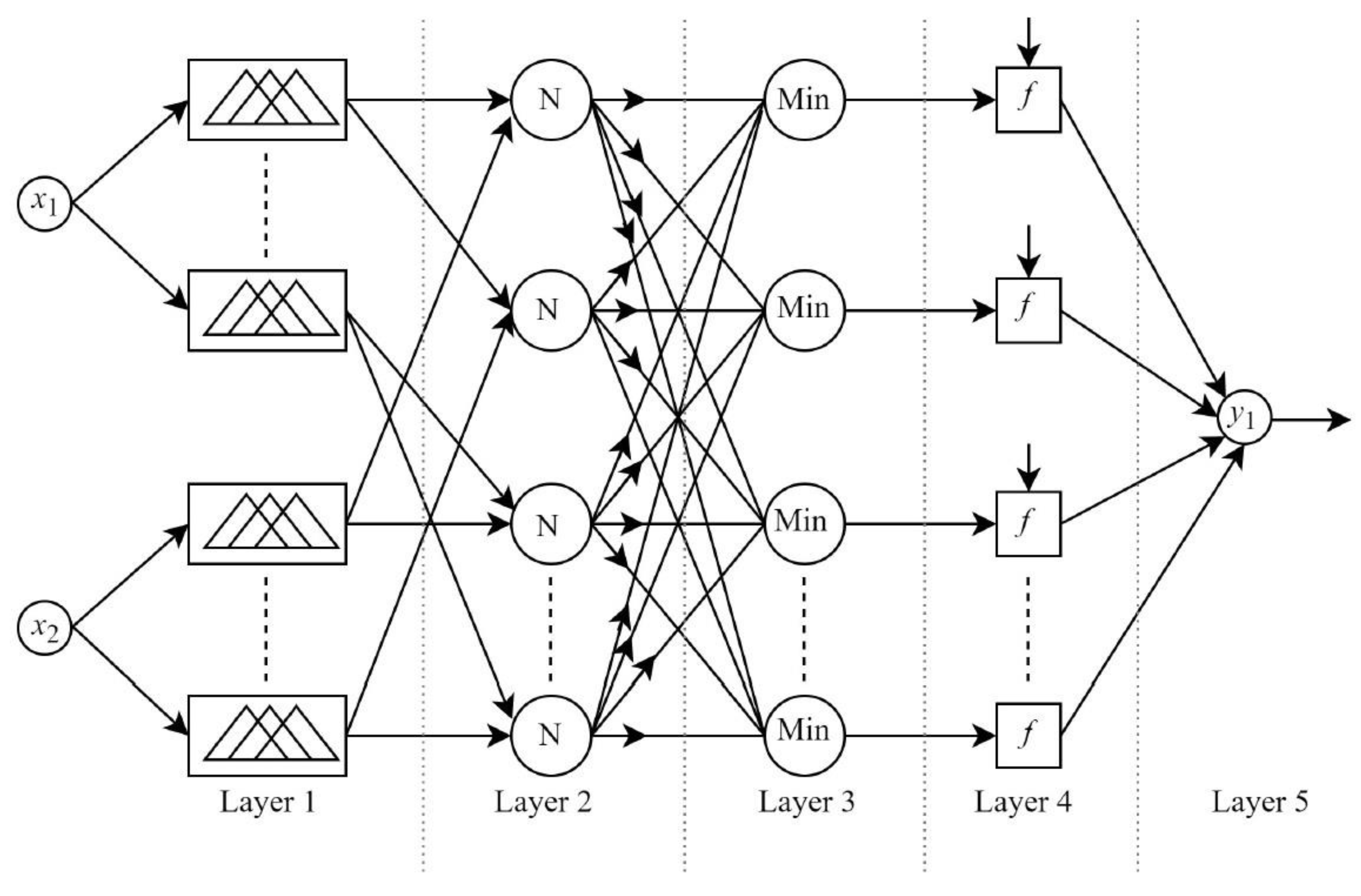
3.1. Hybrid Neuro-Fuzzy PID Controller

The adaptive neuro-fuzzy inference system (ANFIS) combines the benefits of neural networks and fuzzy logic systems. The ANFIS was first designed by Mr. Jang in 1995 [24,25,26]. A fuzzy logic system offers a structural framework for neural networks based on membership functions and fuzzy rules (if–then). A connection structure and learning capabilities are provided by neural networks to the fuzzy logic system [26]. To improve the system efficiency, the role of artificial neural networks is to train and optimize the fuzzy parameters in membership functions [26]. The structure of an ANFIS with two inputs and one output is depicted in Figure 4. The ANFIS consists of five layers, and each layer is composed of several nodes. To fuzzify the inputs, several computing nodes with activation functions based on fuzzy logic membership functions are used to make up Layer 1. The role of Layer 2 is to select the minimum value of the inputs. In Layer 3, the normalization of each input is carried out. Then, the outputs of Layer 3 are applied to the defuzzifiers in Layer 4. In the last layer, the output signals are generated by accumulating all of the fuzzifiers’ outputs. In this study, the ANFIS was integrated with a conventional PID controller to design two hybrid neuro-fuzzy PID controllers (H-NFPID) for the first and the second control loops. The structures of H-NFPID1 and H-NFPID2 are shown in Figure 5. In Figure 5a, the error tracking and its derivative obtained from the values of the drill bit and reference velocities are considered as the inputs of the H-NFPID1 controller:
e 1 = k e 1 ( Ω * x 7 )
C e 1 = k c e 1 d ( Ω * x 7 ) d t
where  k e 1  and  k c e 1  represent the normalizing coefficients for the inputs of H-NFPID1, while  Ω *  is the desired velocity.
The output of H-NFFPID1 can written as follows:
Δ x 1 * = k p 1 X + k i 1 X d t + k d 1 d e 1 d t
where  k p 1  and  k i 1  are the denormalizing proportional coefficient and integral coefficient, respectively,  k d 1  is the derivative coefficient, and X is the output of ANFIS1.
As shown in Figure 5b, the inputs of the H-NFPID2 controller are the error tracking and its derivative for the angular velocities of the rotary table velocity:
e 2 = k e 2 ( x 1 * x 1 )
C e 2 = k c e 2 d ( x 1 * x 1 ) d t
where  k e 2  and  k c e 2  represent the normalizing coefficients for the inputs of H-NFPID2, while  x 1 *  is the desired angular velocity for the rotary table. The output of H-NFFPID1 can written as follows:
Δ u = k p 2 U + k i 2 U d t + k d 2 d e 2 d t
where  k p 1 k i 1 k d 1 , and U are the denormalizing proportional coefficient, the denormalizing integral coefficient, the derivative coefficient, and the output of ANFIS2, respectively. The objective of the derivative term used in the proposed H-NFPID1 and H-NFPID2 controllers is to decrease the settling time and enhance the stability of the drill string. On the other hand, ANFIS1 and ANFIS2 were designed with minimum fuzzy rules for the first and second control loops, respectively, in order to decrease the computational burden. Here, three Gaussian functions were employed as input membership functions for the two ANFIS controllers, in addition to only nine fuzzy rules.

3.2. Design of the Feedforward Term

One of the main contributions of this study is the use of a feedforward term in each control loop in the case of a cascade control scheme for a drill string system. The major benefit of the feedforward term is the provision of a fast dynamic response when there are changes in the angular velocity reference and the WOB. To estimate the feedforward term, the system model should be studied in the steady state without stick–slip vibrations as follows [40]:
x ˙ 1 = x ˙ 2 = x ˙ 3 = x ˙ 4 = x ˙ 5 = x ˙ 6 = x ˙ 7 = 0
x 1 = x 3 = x 5 = x 7 = Ω *
In Equation (22), the feedforward term used in the first control loop is the angular velocity reference.
x F = Ω *
Then, by substituting Equations (21) and (22) into (4), the feedforward term used in the second control loop is defined as follows:
u F F = ( c t + c r ) Ω * + k t x 2 c t Ω *
where  x 2  can be written according to Equations (21), (22), and (4) as follows:
x 2 = 1 k t [ c t Ω * + ( c t + c t l ) Ω * + k t l x 4 c t l Ω * ]
Equation (16) can simplified as follows:
x 2 = k t l x 4 k t
According to Equation (4),  x 4  in the steady state can be defined as
x 4 = 1 k t l [ c t l Ω * + ( c t l + c t b ) Ω * + k t b x 6 c t b Ω * ]
The simplified version of Equation (27) is described by Equation (28):
x 4 = k t b x 4 k t l
In addition,  x 6  should be defined in the steady state as follows:
x 6 = 1 k t b [ c t b Ω * + ( c t b + c b ) Ω * + T f b ( X ) ]
where the nonlinear torque on the bit  T f b  can be estimated in the case without stick–slip vibrations and in the steady state as follows:
T f b ( X ) = W o b R b u b ( Ω * )
Finally, the torque feedforward term for the second control loop is given using the following simplified equation:
u F = c r Ω * + c b Ω * + W o b R b u b ( Ω * )
Regarding Equation (31), the feedforward term for the second control loop is estimated according to some system parameters, the angular velocity reference, and the WOB. The WOB can be adjusted by the operator.

4. Simulation Results

To confirm that the proposed CFF-NFPID control approach can be practically implemented in drill string systems, extensive simulations were carried out using Matlab/Simulink. The four-DOF drill string mathematical model presented in Equation (4) was implemented in an embedded Matlab function as program lines to simulate the behavior of a drill string system. This mathematical model considered nonlinear rock–bit interactions, including the mud-drilling effect and friction torque. Furthermore, the studied controllers were implemented using components of Matlab/Simulink toolboxes. The global system parameters and the coefficients of the controllers are illustrated in Table 1. The performance of the proposed CFF-NFPID approach was tested under three conditions: (i) a stepwise and slow change in the reference velocity; (ii) variation in the WOB at a constant reference velocity; (iii) parametric uncertainties at a constant reference velocity. To evaluate the efficacy of the CFF-NFPID strategy, a quantitative comparison with several controllers (CFF-FPID, CFF-PID, SMC [15], SMC [16], cascade PID, and conventional PID) was conducted.

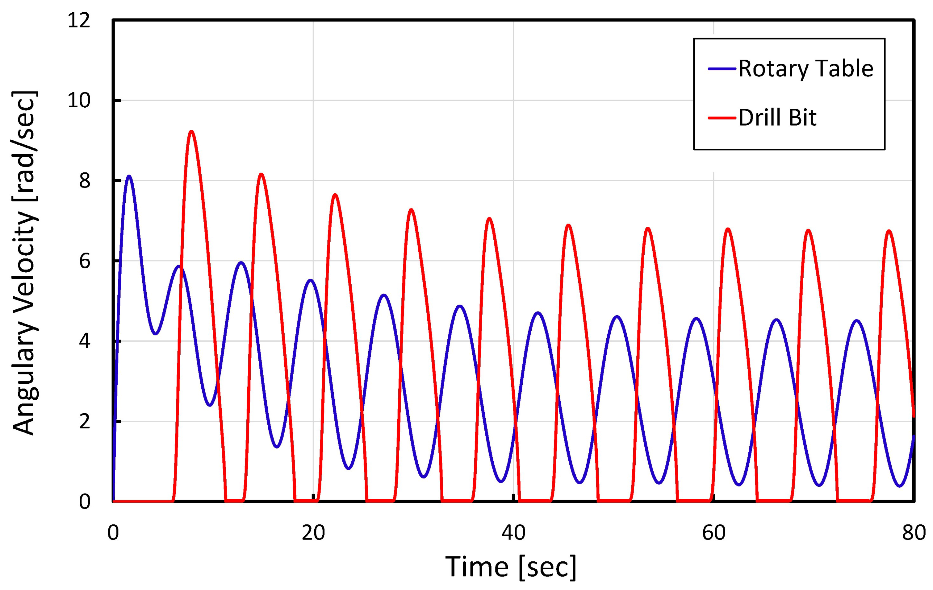
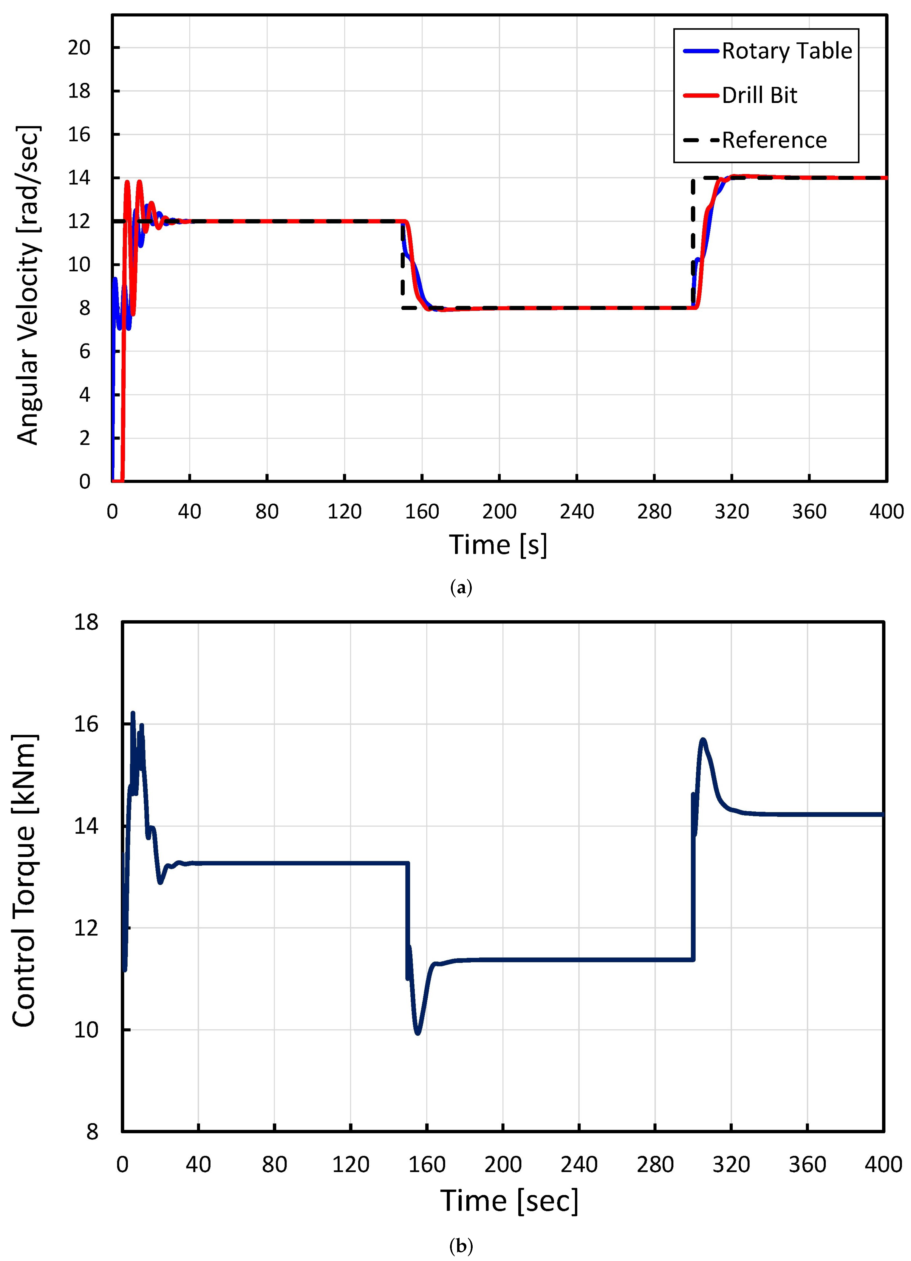
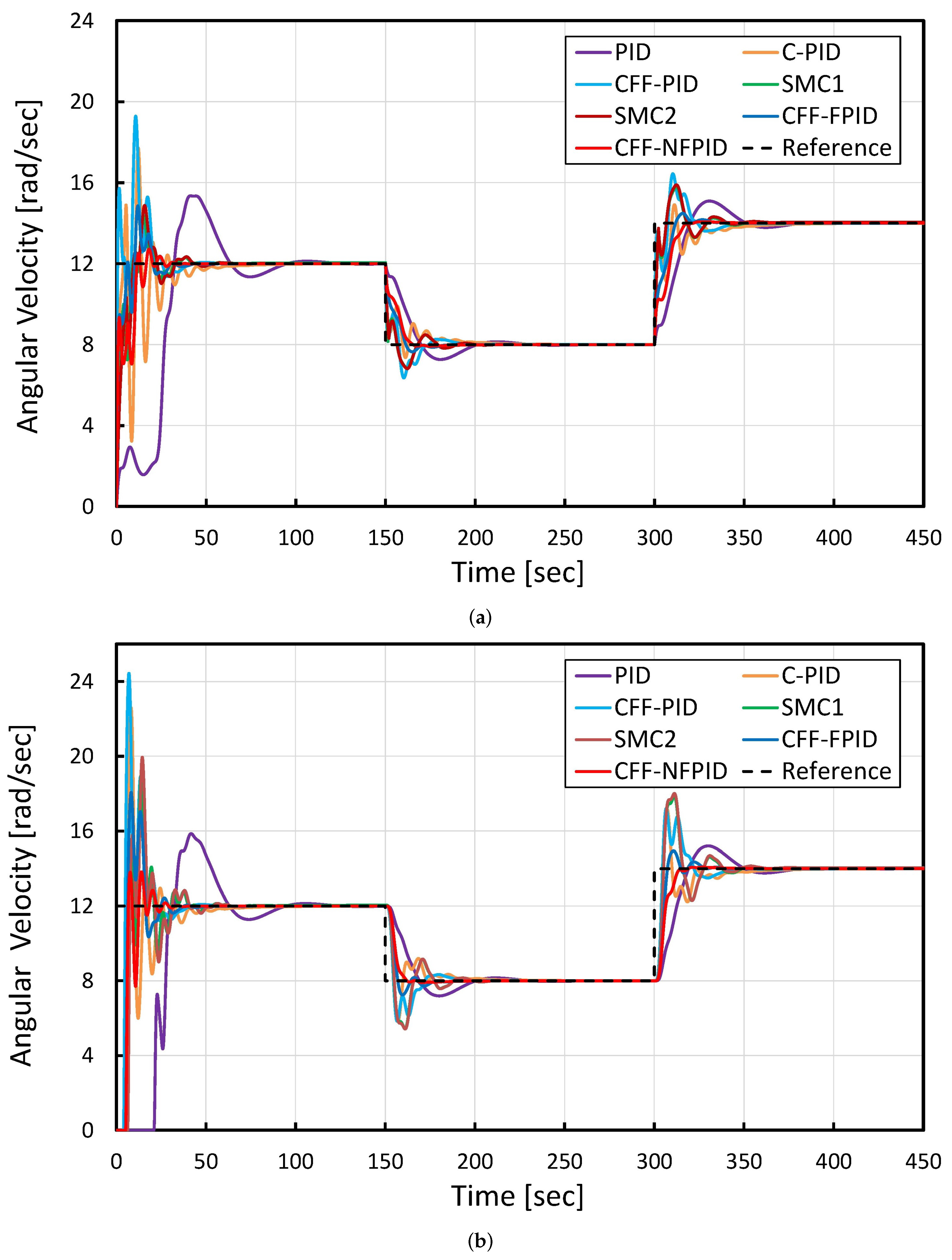
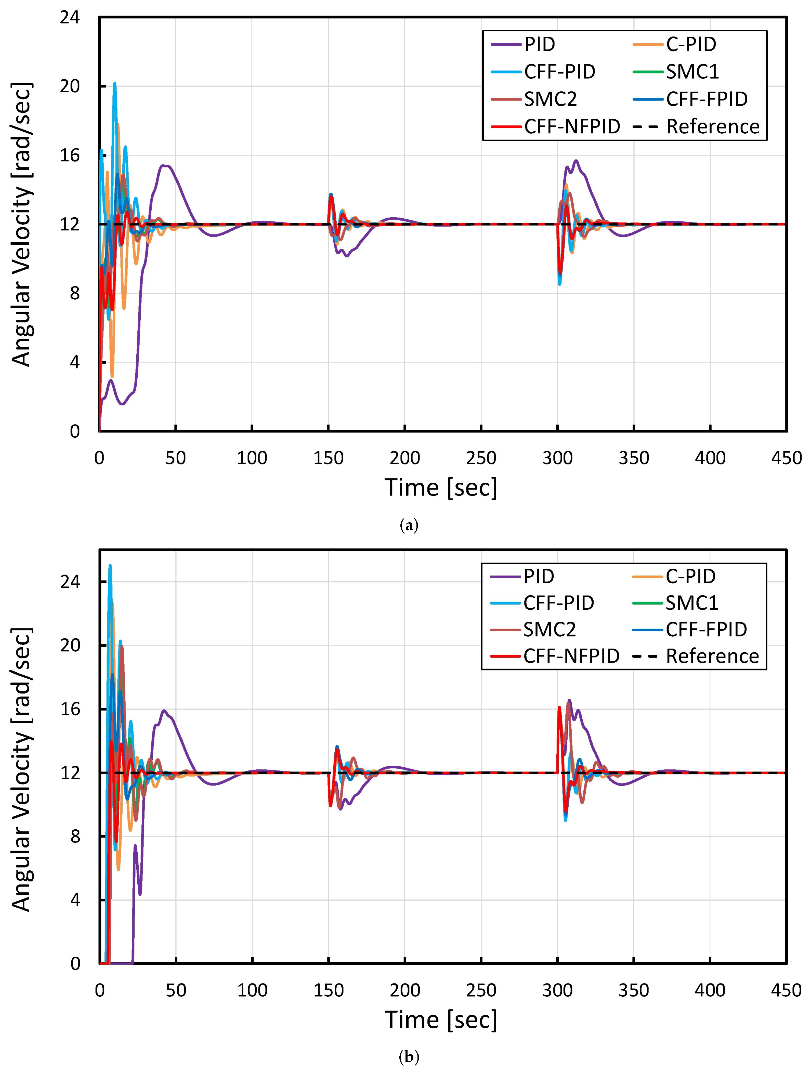
4.1. Effect of Applying the Proposed CFF-NFPID Approach to a Drill String System

Figure 6 shows the behavior of a drill string system with a WOB of 97 kN and without a closed control loop. It can be observed that the drill string system suffered from stick–slip phenomena in this situation. The velocities of the rotary table and drill bit periodically oscillated from zero to a value that surpassed the rotary table’s velocity in addition to the variation in the drill bit velocity. These oscillations negatively affected the drill string components and could cause failure or complete damage. For this reason, the utilization of closed-loop control in drill string systems is imposed as a compulsory solution for dampening these oscillations. As described in this section, the proposed CFF-NFPID control scheme was implemented to eliminate stick–slip vibrations. Furthermore, the performance of the proposed CFF-NFPID strategy was tested when undergoing sudden and slow changes in the drill bit reference when the WOB was set to 100 kN, as shown in Figure 7 and Figure 8.
As illustrated in Figure 7a, for the time range from 0 s to 150 s, the reference angular velocity was set to 12 rad/s. The proposed controller dampened the stick–slip vibration and guaranteed a quick stabilization of both the rotary table and the drill bit to the reference angular velocity at t = 25.33 s and t = 24.73 s, respectively, with a very small peak overshoot. Then, a stepwise decrease in the change in the drill bit reference from 12 rad/s to 8 rad/s was applied at 150 s. The angular velocities of both the rotary table and the drill bit were quickly stabilized to the desired drill bit reference without undershoots at t = 25.33 s and t = 24.73 s, respectively. Furthermore, a large and sudden increase in the change in the drill bit reference from 8 rad/s to 14 rad/s occurred at 300 s. In addition, the CFF-NFPID strategy provided a fast stilling time for the angular velocities of both the rotary table and the drill bit at t = 15.40 s and t = 12.50 s, respectively, without overshoots. The simulation response of the drive torque with sudden changes in the drill bit reference is presented in Figure 7b. It can be clearly observed that the drive torque increased or decreased depending on the change in the angular velocity reference with a small overshoot/undershoot (less than  18 % ). As presented in Figure 8a, a slow decrease in the variation in the reference angular velocity from 12 rad/s to 8 rad/s occurred from 75 s to 175 s. Moreover, a slow increase in the variation in the reference angular velocity from 8 rad/s to 12 rad/s occurred from 250 s to 350 s. Despite these changes, the proposed CFF-NFPID controller guaranteed accurate angular velocity tracking. On the other hand, the drive torque increased or decreased depending on the slow variation in the angular velocity reference with very small deviations, as presented in Figure 8b.

4.2. Quantitative Comparison under Critical Conditions

The performance of the CFF-NFPID controller was compared with that of the CFF-FPID, CFF-PID, and SMC controllers proposed in [15], the SMC proposed in [16], and the cascade PID and conventional PID controllers when there were sudden changes in the desired drill bit velocity to evaluate the benefits of using the suggested control scheme. All of the controllers were simulated on the drill string system with the parameters listed in Table 1. Figure 9 shows the simulated responses of the different controllers when there were sudden variations in the drill bit’s angular velocity reference. Furthermore, a quantitative performance analysis in terms of the peak overshoot/undershoot and the settling time of the different controllers is summarized in Table 2. It can be noted that the proposed CFF-NFPID approach provided high-performance control in the dynamic state (fast settling time and very small overshoot/undershoot) in comparison with the other controllers. In the steady state, all of the controllers succeeded in regulating the velocities of both the drill bit and rotary table to follow the desired velocity. It can also be noted in Table 2 that employing the cascade PID controller improved the control performance in comparison with that of the conventional PID controller. On the other hand, the CFF-PID controller provided enhanced control performance in comparison with that of the SMC algorithms proposed in [15,16]. In addition, we noticed that, with the exception of the proposed CFF-NFPID controller, the CFF-FPID controller provided better performance than that of the other controllers in all cases of changes in the reference.
Secondly, another quantitative comparison was conducted when considering a sudden change in the WOB from 10 kN to 8 kN at 150 s and from 8 kN to 12 kN at 300 s. The reference angular velocity was set to 12 rad/s. The simulation waveforms obtained with different controllers are shown in Figure 10. The detailed control performance of all controllers is presented in Table 3. High-performance control in terms of the settling time and peak overshoot was guaranteed by the proposed controller in comparison with the other controllers. On the other hand, the C-PID controller improved the performance obtained with the conventional PID controller. The CFF-PID controller provided a fast settling time and low peak overshoot/undershoot in comparison with the SMC algorithms, as we noted in the previous test. Due to the fact that the design of the feedforward term requires some system parameters to be set, a quantitative comparison in the case of parametric uncertainty was conducted. The purpose of this critical test was to show if the proposed control scheme was able to keep the superior performance that it had in the previous tests. The obtained waveforms are presented in Figure 11, and the detailed control performance is summarized in Table 4. It can be clearly observed that the control performance of all controllers was degraded in this critical scenario. However, the proposed CFF-NFPID controller still provided better performance than that of the other controllers. Generally, the simulation results that were obtained proved the greater ability of the proposed control scheme to suppress stick–slip vibrations. In addition, the CFF-NFPID controller achieved high control performance in terms of the response time overshoot/undershoot in different critical scenarios in comparison with the other controllers.
Figure 11 shows the simulated responses of the OH-IT2FPID+I controller with parametric uncertainties. In this case, the parameters  J r ,   k t ,   d t ,  and  d r  were changed, and the reference velocity was set to 12 rad/s. It is clear that the parametric uncertainties did not degrade the performance of the proposed OH-IT2FPID+I controller. This led to the achievement of a small overshoot and fast response time.
To demonstrate the effectiveness of using the proposed control scheme, the OH-IT2FPID+I controller was compared with a conventional PID controller, the SMC from [16], the SMC from [15], and the OH-IT1FPID+I controller. Figure 9 shows the simulation time response of the velocities with variations in the reference angular velocity when using different controllers. The results showed a large undershoot with large decreases in the reference velocity in the SMC algorithms proposed in [15,16], which could cause instability in a drill string system. Figure 10 shows the simulation time response of the velocities with variations in the WOB when using different controllers. In Figure 11, it is clear that the proposed OH-IT2FPID+I controller produced high-performance control with parametric uncertainty in terms of the peak overshoot and settling time. Table 4 depicts a quantitative analysis of the performance in terms of the peak overshoot and settling time for all controllers in the different situations. It is clear that the proposed OH-IT2FPID+I controller was more effective than the other controllers in all of the tested situations.

5. Conclusions

In this study, a fast and intelligent cascade control scheme based on hybrid adaptive neuro-fuzzy PID and feedforward terms (CFF-NFPID) was presented for an oil well drill string system. The controller’s main objective was to mitigate the torsional stick–slip vibration phenomena in oil well drill strings by controlling the velocities of the drill string components to remain at a desired value. The key feature of the CFF-NFPID controller is the estimation of the top drive velocity reference from the drill bit velocity and its reference via the first control loop. Then, a second control loop was employed to regulate the top drive velocity to its reference. Each control loop was designed based on a hybrid adaptive neuro-fuzzy PID controller and feedforward term. The feedforward (FF) term provides an ideal control action that helps to achieve a fast settling time of the measured signal to the reference signal. The effectiveness of the proposed control scheme was evaluated via simulations in Matlab/Simulink. The obtained results showed the outstanding performance of the proposed CFF-NFPID controller in comparison with that of the fuzzy feedforward (CFF-FPID) controller, sliding-mode controller, cascade feedforward PID controller, cascade PID controller, and conventional PID controller when there were variations in the weight on the bit and the desired drill bit rotary speed. Although the design of feedforward terms requires exact system parameters, the proposed CFF-NFPID controller maintained its superiority over other controllers under parametric uncertainties. Future work will involve combining the predictive capabilities of model predictive control with the proposed cascade control scheme to significantly improve the response time, stability, adaptability, operational efficiency, safety, and cost savings.

Author Contributions

Conceptualization, A.L. and M.G.; methodology, A.L.; software, A.L.; validation, A.L.; formal analysis, A.L.; investigation, A.L.; resources, M.G.; data curation, A.L. and M.G.; writing—original draft preparation, A.L.; writing—review and editing, M.G.; visualization, M.G.; supervision, M.G.; project administration, M.G.; funding acquisition, M.G. All authors have read and agreed to the published version of the manuscript.

Funding

This research was funded by the Qatar National Research Fund (grant number NPRP10-0101-170081).

Institutional Review Board Statement

Not applicable.

Informed Consent Statement

Not applicable.

Data Availability Statement

The raw data supporting the conclusions of this article will be made available by the corresponding author on request.

Conflicts of Interest

The authors declare no conflicts of interest.

Abbreviations

The following abbreviations are used in this manuscript:
ANNartificial neural network
ANFISadaptive neuro-fuzzy inference system
BHAbottom hole assembly
C-PIDcascade PID
CFF-PIDcascade feedforward PID
CFF-FPIDcascade feedforward fuzzy PID
CFF-NFPIDcascade feedforward neuro-fuzzy PID
DOFdegrees of freedom
FFfeedforward
FLCfuzzy logic control
H-NFPIDhybrid neuro-fuzzy PID
NFPIDneuro-fuzzy PID
PIproportional–integral
PIDproportional–integral–derivative
ROPrate of penetration
RPMrevolutions per minute
SMCsliding-mode control
WOBweight on bit

References

  1. Márquez, M.S.; Boussaada, I.; Mounier, H.; Niculescu, S.I. Analysis and Control of Oilwell Drilling Vibrations: A Time-Delay Systems Approach; Advances in Industrial Control; Springer: Berlin/Heidelberg, Germany, 2015. [Google Scholar]
  2. Jansen, J.D.; Van Den Steen, L. Active damping of self-excited torsional vibrations in oil well drillstrings. J. Sound Vib. 1995, 179, 647–668. [Google Scholar] [CrossRef]
  3. Zhu, X.; Tang, L.; Yang, Q. A literature review of approaches for stick-slip vibration suppression in oilwell drillstring. Adv. Mech. Eng. 2014, 6, 967952. [Google Scholar] [CrossRef]
  4. Vaziri, V.; Kapitaniak, M.; Wiercigroch, M. Suppression of drill string stick–slip vibration by sliding mode control: Numerical and experimental studies. Eur. J. Appl. Math. 2018, 29, 805–825. [Google Scholar] [CrossRef]
  5. Dong, G.; Chen, P. A review of the evaluation, control, and application technologies for drill string vibrations and shocks in oil and gas well. Shock Vib. 2016, 2016, 7418635. [Google Scholar] [CrossRef]
  6. Wu, S.X.; Paez, L.; Partin, U.; Agnihotri, M. Decoupling stick-slip and whirl to achieve breakthrough in drilling performance. In Proceedings of the IADC/SPE Drilling Conference and Exhibition, New Orleans, LA, USA, 2–4 February 2010; p. 128767. [Google Scholar]
  7. Tucker, R.W.; Wang, C. Torsional vibration control and cosserat dynamics of a drill-rig assembly. Meccanica 2003, 38, 145–161. [Google Scholar] [CrossRef]
  8. Derbal, M.; Gharib, M.; Refaat, S.S.; Palazzolo, A.; Sassi, S. Fractional-order controllers for stick-slip vibration mitigation in oil well drill-strings. J. Low Freq. Noise Vib. Act. Contr. 2021, 40, 1571–1584. [Google Scholar] [CrossRef]
  9. Puebla, H.; Alvarez-Ramirez, J. Suppression of stick-slip in drillstrings: A control approach based on modeling error compensation. J. Sound Vib. 2008, 310, 881–901. [Google Scholar] [CrossRef]
  10. Christoforou, A.; Yigit, A. Fully coupled vibrations of actively controlled drillstrings. J. Sound Vib. 2003, 267, 1029–1045. [Google Scholar] [CrossRef]
  11. Serrarens, A.; Van De Molengraft, M.; Kok, J.; Van den Steen, L. H/sub/spl infin//control for suppressing stick-slip in oil well drillstrings. IEEE Control Syst. Mag. 1998, 18, 19–30. [Google Scholar]
  12. Yigit, A.; Christoforou, A. Coupled torsional and bending vibrations of actively controlled drillstrings. J. Sound Vib. 2000, 234, 67–83. [Google Scholar] [CrossRef]
  13. Tashakori, S.; Vossoughi, G.; Zohoor, H.; Van de Wouw, N. Prediction-based control for mitigation of axial–torsional vibrations in a distributed drill-string system. IEEE Trans. Contr. Syst. Techol. 2021, 30, 277–293. [Google Scholar] [CrossRef]
  14. Al-Hiddabi, S.; Samanta, B.; Seibi, A. Non-linear control of torsional and bending vibrations of oilwell drillstrings. J. Sound Vib. 2003, 265, 401–415. [Google Scholar] [CrossRef]
  15. Navarro-López, E.M.; Cortés, D. Sliding-mode control of a multi-DOF oilwell drillstring with stick-slip oscillations. In Proceedings of the 2007 IEEE American Control Conference, New York, NY, USA, 9–13 July 2007; pp. 3837–3842. [Google Scholar]
  16. Liu, Y. Suppressing stick-slip oscillations in underactuated multibody drill strings with parametric uncertainties using sliding-mode control. IET Control Theory Appl. 2015, 9, 91–102. [Google Scholar] [CrossRef]
  17. Aguiar, C.; Leite, D.; Pereira, D.; Andonovski, G.; Škrjanc, I. Nonlinear modeling and robust LMI fuzzy control of overhead crane systems. J. Frankl. Inst. 2021, 358, 1376–1402. [Google Scholar] [CrossRef]
  18. Lahlouh, I.; Rerhrhaye, F.; Elakkary, A.; Sefiani, N. Experimental implementation of a new multi input multi output fuzzy-PID controller in a poultry house system. Heliyon 2020, 6, e04645. [Google Scholar] [CrossRef] [PubMed]
  19. dos Santos, W.S.; Torres, P.F.; Brito, A.U.; Galhardo, M.A.B.; Macêdo, W.N. A novel fuzzy controller for photovoltaic pumping systems driven by general-purpose frequency converters. Sustain. Energy Technol. Assessments 2020, 40, 100758. [Google Scholar] [CrossRef]
  20. Ilyas, A.; Khan, M.R.; Ayyub, M. FPGA based real-time implementation of fuzzy logic controller for maximum power point tracking of solar photovoltaic system. Optik 2020, 213, 164668. [Google Scholar] [CrossRef]
  21. Pietrosanti, S.; Alasali, F.; Holderbaum, W. Power management system for RTG crane using fuzzy logic controller. Sustain. Energy Technol. Assessments 2020, 37, 100639. [Google Scholar] [CrossRef]
  22. Zhang, L.; Zhu, L.; Hua, C.; Qian, C. Adaptive neural network control for a class of interconnected pure-feedback time-delay nonlinear systems with full-state constraints and unknown measurement sensitivities. Neurocomputing 2021, 461, 147–161. [Google Scholar] [CrossRef]
  23. Fu, X.; Li, S. Control of single-phase grid-connected converters with LCL filters using recurrent neural network and conventional control methods. IEEE Trans. Power Electron. 2015, 31, 5354–5364. [Google Scholar] [CrossRef]
  24. Mehrasa, M.; Babaie, M.; Zafari, A.; Al-Haddad, K. Passivity ANFIS-Based control for an intelligent compact multilevel converter. IEEE Trans. Ind. Informatics 2021, 17, 5141–5151. [Google Scholar] [CrossRef]
  25. Areed, F.G.; Haikal, A.Y.; Mohammed, R.H. Adaptive neuro-fuzzy control of an induction motor. Ain Shams Eng. J. 2010, 1, 71–78. [Google Scholar] [CrossRef]
  26. Ebrahimi, M.; Qaderi, F. Determination of the most effective control methods of SO2 pollution in Tehran based on adaptive neuro-fuzzy inference system. Chemosphere 2021, 263, 128002. [Google Scholar] [CrossRef] [PubMed]
  27. Laib, A.; Talbi, B.; Krama, A.; Gharib, M. Hybrid Interval Type-2 Fuzzy PID+ I Controller for a Multi-DOF Oilwell drill string System. IEEE Access 2022, 10, 67262–67275. [Google Scholar] [CrossRef]
  28. Jin, X.; Chen, K.; Zhao, Y.; Ji, J.; Jing, P. Simulation of hydraulic transplanting robot control system based on fuzzy PID controller. Measurement 2020, 164, 108023. [Google Scholar] [CrossRef]
  29. Li, C.; Mao, Y.; Zhou, J.; Zhang, N.; An, X. Design of a fuzzy-PID controller for a nonlinear hydraulic turbine governing system by using a novel gravitational search algorithm based on Cauchy mutation and mass weighting. Appl. Soft Comput. 2017, 52, 290–305. [Google Scholar] [CrossRef]
  30. Sahoo, B.; Panda, S. Improved grey wolf optimization technique for fuzzy aided PID controller design for power system frequency control. Sustain. Energy Grids Netw. 2018, 16, 278–299. [Google Scholar] [CrossRef]
  31. Ritto, T.G.; Ghandchi-Tehrani, M. Active control of stick-slip torsional vibrations in drill strings. J. Vib. Control 2019, 25, 194–202. [Google Scholar] [CrossRef]
  32. Real, F.F.; Batou, A.; Ritto, T.G.; Desceliers, C. Stochastic modeling for hysteretic bit–rock interaction of a drill string under torsional vibrations. J. Vib. Control 2019, 25, 1663–1672. [Google Scholar] [CrossRef]
  33. Asghar Jafari, A.; Kazemi, R.; Faraji Mahyari, M. The effects of drilling mud and weight bit on stability and vibration of a drill string. J. Vib. Acoust. 2012, 134, 011014. [Google Scholar] [CrossRef]
  34. Ghasemi, M.; Song, X. Trajectory tracking and rate of penetration control of downhole vertical drilling system. J. Dyn. Syst. Meas. Control 2018, 140, 091003. [Google Scholar] [CrossRef]
  35. Ke, C.; Song, X. Drilling control system using an equivalent input disturbance-based control with a neutral-type axial-torsional coupled dynamics model. J. Dyn. Syst. Meas. Control 2019, 141, 121013. [Google Scholar] [CrossRef]
  36. Saldivar, B.; Mondié, S.; Niculescu, S.I.; Mounier, H.; Boussaada, I. A control oriented guided tour in oilwell drilling vibration modeling. Annu. Rev. Control 2016, 42, 100–113. [Google Scholar] [CrossRef]
  37. Abdulgalil, F.; Siguerdidjane, H. Backstepping design for controlling rotary drilling system. In Proceedings of the 2005 IEEE Conference on Control Applications, Toronto, ON, Canada, 28–31 August 2005; pp. 120–124. [Google Scholar]
  38. Liu, Y.; Lin, W.; Chávez, J.P.; De Sa, R. Torsional stick-slip vibrations and multistability in drill strings. Appl. Math. Model. 2019, 76, 545–557. [Google Scholar] [CrossRef]
  39. Monteiro, H.L.; Trindade, M.A. Performance analysis of proportional-integral feedback control for the reduction of stick-slip-induced torsional vibrations in oil well drillstrings. J. Sound Vib. 2017, 398, 28–38. [Google Scholar] [CrossRef]
  40. Fu, M.; Zhang, P.; Li, J.; Wu, Y. Observer and reference governor based control strategy to suppress stick-slip vibrations in oil well drill string. J. Sound Vib. 2019, 457, 37–50. [Google Scholar] [CrossRef]
Figure 1. The studied system: (a) a drilling rig with a drill string system; (b) mathematical model of the drill string system [15].
Applsci 14 05225 g001
Figure 3. The proposed cascade control scheme.
Applsci 14 05225 g003
Figure 4. The structure of the ANFIS.
Applsci 14 05225 g004
Figure 5. The proposed hybrid neuro-fuzzy PID controller: (a) ANFIS1; (b) ANFIS2.
Applsci 14 05225 g005
Figure 6. Simulation results with a WOB of 97 kN and without a closed control loop.
Applsci 14 05225 g006
Figure 7. Drill string stabilization when using the CFF-NFPID controller with sudden change in the drill bit reference and WOB = 100 kN: (a) angular velocities; (b) control torque.
Applsci 14 05225 g007
Figure 8. Drill string stabilization when using the CFF-NFPID controller with slow changes in the drill bit reference and WOB = 100 kN: (a) angular velocities; (b) control torque.
Applsci 14 05225 g008
Figure 9. Simulated waveforms of the angular velocity during variations in the desired angular velocity with different controllers: (a) rotary table; (b) drill bit.
Applsci 14 05225 g009
Figure 10. Simulated waveforms of the angular velocities during variations in the WOB and constant desired velocity with different controllers: (a) rotary table; (b) drill bit.
Applsci 14 05225 g010
Figure 11. Simulated waveforms of the angular velocities in the case of parametric uncertainty with different controllers: (a) rotary table; (b) drill bit.
Applsci 14 05225 g011
Table 1. Numerical values of the drill string system parameters [15].
ParameterElement(s)SymbolValueUnits
Inertiarotary table   J r 930kg· m 2
Inertiadrill collar   J l 750kg· m 2
Inertiadrill pipes   J p 2782.25kg· m 2
Inertiadrill bit   J b 471.97kg· m 2
Stiffnessdrill pipes and rotary table   k t 698.06N·m/rad
Stiffnessdrill pipes and drill collar   k t l 1080N·m/rad
Stiffnessdrill bit and drill collar   k t b 907.48N·m/rad
Dampingdrill pipe and rotary table   d t 139.61N·m·s/rad
Dampingdrill collar and drill pipe   d t l 190N·m·s/rad
Dampingdrill bit and drill collar   d t b 181.49N·m·s/rad
Dampingdrill bit and mud drilling   d b 50N·m·s/rad
Weight on bitdrill bitWOB100kN
Radiusdrill bit   R b 0.156m
Factordrill bit   γ b 0.9
Limit velocity   D v   10 6 rad/s
Drive torque   T m 10kN·m
Coefficient of static friction   μ s b 0.8
Coefficient of Coulomb friction   μ c b 0.5
Coefficient of viscous damping   d r 425N·m·s/rad
Table 2. Quantitative comparison with a fixed WOB and variations in the desired angular velocity.
Stepwise Increase in the Angular Velocity
Reference 0→12 rad/s
Stepwise Decrease in the Angular Velocity
Reference 12→8 rad/s
Stepwise Increase in the Angular Velocity
Reference 8→14 rad/s
Angular Velocity
of the Rotary Table
Angular Velocity
of the Drill Bit
Angular Velocity
of the Rotary Table
Angular Velocity
of the Drill Bit
Angular Velocity
of the Rotary Table
Angular Velocity
of the Drill Bit
  T r  [s]   U p
[rad/s]
  T r  [s]   U p
[rad/s]
  T r  [s]   U p
[rad/s]
T r  [s]   U p
[rad/s]
  T r  [s]   U r
[rad/s]
  T r  [s]   U r
[rad/s]
PID87.873.8687.943.3550.050.8251.020.7445.651.2145.891.09
C-PID50.635.7154.1210.6042.150.6539.352.1641.430.9238.773.16
CFF-PID35.47.5134.112.0835.121.7234.512.2834.432.5733.893.38
SMC [15]39.452.2547.566.7336.021.5133.921.1536.033.8726.631.79
SMC [16]40.563.8348.777.9636.292.5734.651.1936.624.0235.211.89
CFF-FPID28.682.8532.616.0718.110.3624.610.7618.210.4824.220.94
CFF-NFPID25.330.7224.731.8213.130.0010.780.0015.400.0012.500.00
Table 3. Quantitative comparison using a constant desired angular velocity and variations in the WOB.
Stepwise Decrease in the WOB 100→120 kNStepwise Increase in the WOB 120→80 kN
Angular Velocity of the
Rotary Table
Angular Velocity of the
Drill Bit
Angular Velocity of the
Rotary Table
Angular Velocity of the
Drill Bit
Settling
Time [s]
Overshoot
[rad/s]
Settling
Time [s]
Overshoot
[rad/s]
Settling
Time [s]
Overshoot
[rad/s]
Settling
Time [s]
Overshoot
[rad/s]
PID51.022.2950.561.8456.274.5956.373.67
C-PID19.021.1715.562.0827.012.3130.834.13
CFF-PID16.890.9819.482.0623.361.9520.594.11
SMC [15]19.320.9126.872.1922.661.7831.864.36
SMC [16]19.310.8926.862.1922.651.7831.852.37
CFF-FPID14.130.6217.862.0720.091.0920.924.13
CFF-NFPID11.820.7912.452.0615.751.0916.234.12
Table 4. Quantitative comparison using a constant desired angular velocity and parametric uncertainties.
Stepwise Increase in the Angular Velocity Reference 0→12 rad/s
in the Case of Parametric Uncertainty
Angular Velocity of the Rotary TableAngular Velocity of the Drill Bit
Settling Time [s]Undershoot [rad/s]Settling Time [s]Undershoot [rad/s]
PID95.955.4996.194.93
C-PID42.235.5844.319.19
CFF-PID48.976.2349.6110.37
SMC [15]39.621.9546.596.56
SMC [16]40.762.4747.987.51
CFF-FPID28.762.5935.755.41
CFF-NFPID26.630.9533.842.29
Disclaimer/Publisher’s Note: The statements, opinions and data contained in all publications are solely those of the individual author(s) and contributor(s) and not of MDPI and/or the editor(s). MDPI and/or the editor(s) disclaim responsibility for any injury to people or property resulting from any ideas, methods, instructions or products referred to in the content.

