Article

Hydrothermal Manufacture of Zeolitic Lightweight Aggregates from Clay and Marine Plastic Litter

1
Department of Geology and Geochemistry, Autonomous University of Madrid, 28049 Madrid, Spain
2
Department of Physical Chemistry, Faculty of Environmental Sciences and Biochemistry, University of Castilla-La Mancha, Avenida Carlos III, s/n, 45071 Toledo, Spain
*
Author to whom correspondence should be addressed.
Appl. Sci. 2024, 14(17), 7674; https://doi.org/10.3390/app14177674
Submission received: 24 July 2024 / Revised: 13 August 2024 / Accepted: 28 August 2024 / Published: 30 August 2024

Abstract

:
Mixed plastic fraction (MPF) from marine litter was investigated as a pore-forming agent in formulations with kaolin and a rejected Mg-clay (rich in smectite and sepiolite) to obtain innovative zeolitic lightweight aggregates. Round granules of ~10 mm in diameter were shaped and fired at 600 °C (mixtures of kaolin with 0, 5, 10, and 20 wt.% MPF) and 900 °C (mixtures of rejected Mg-clay:kaolin (1:0, 2:1, 1:2; 0:1) with 10 wt.% MPF). The fired specimens were hydrothermally treated in a 3M NaOH solution at 150 °C for 24 h. Mixtures containing 20 wt.% MPF led to specimen crumbling, while those with 5 and, especially, 10 wt.% MPF favored a significant crystallization of zeolites and feldspathoids (50–80%), highlighting cancrinite, nepheline, zeolite A, and analcime. The resulting materials were lightweight (1.5–1.8 g/cm3) and their crushing strength increased substantially with the hydrothermal treatment, from 0.04–0.5 MPa to 2.3–5.5 MPa after zeolitization. High content of rejected Mg-clay in the mixture (>67%) negatively affected the zeolitization and the properties of the final aggregate, while 33 wt.% was adequate, increasing slightly the crushing strength (3.4 vs. 3.1 MPa). These findings contribute to plastic waste circularity and sustainability/technological progress in materials production.

1. Introduction

Annually, 10 million tons of waste reach the seas and oceans, a problem of global magnitude [1,2]. Despite the heterogeneous nature of marine litter, plastic is the most predominant fraction [3]. Its presence can amount to several kg per km2 (millions of fragments) in various oceanic areas, including the Mediterranean Sea [4], which directly affects marine organisms that ingest them [5]. Therefore, it is necessary to look for alternatives to reduce the impact of plastic waste.
Regarding plastic application as a pore-forming agent in ceramic materials, this type of research has been usually restricted mainly to biomedical ceramics [6,7]. The addition of plastic to produce materials for construction has hardly been studied. Some of the first contributions in this sense were associated with the manufacture of lightweight aggregates (porous granular ceramic materials) in the patents by Kirschner [8] and Malloy et al. [9]. However, this research line remained dormant for years, and it was not until years later that plastic residues were studied again in ceramic formulations. Some works published by Moreno-Maroto et al. [10,11] stand out, in which the role of household plastic waste as a porogenic additive in expanded lightweight aggregates was studied, also using other mineral wastes in the mixtures (e.g., mine tailings).
It is worth noting that the manufacture of lightweight aggregates can be carried out through four routes: (i) cold bonding: combining raw materials with pozzolanic capacity, such as fly ash, calcium hydroxide, and Portland cement, to obtain hardened aggregates after mixing with water [12,13]; (ii) autoclaving: starting from raw materials that are also binders, the shaped granules undergo an autoclave curing process at temperatures > 100 °C to promote hardening [12,14]; (iii) geopolymerization: mineral precursors rich in aluminosilicates are mixed with an alkaline activator solution until a paste is obtained, which hardens under suitable curing conditions [15]. Foaming agents, such as silica fume, can be added to develop a lighter structure [16]; and (iv) firing or sintering: this is the most common method to obtain lightweight aggregates, as with suitable raw materials and manufacturing conditions (generally using rotary kilns), it can lead to very light and porous materials.
From an environmental standpoint, the above processes present aspects for improvement: in the case of cold bonding and autoclaving, the starting raw materials are generally obtained at high temperatures to be activated (for example, Portland cement is manufactured at about 1500 °C). Likewise, the rotary kiln firing method involves temperatures that in most cases are between 1050 and 1250 °C [17]. Regarding geopolymerization, although it is not very popular in the manufacture of lightweight aggregates, it is attracting a lot of attention in recent years as a more sustainable method of obtaining alternative binders to Portland cement. Although geopolymerization is usually considered environmentally friendly, the strong impact in the manufacture of its most common activators is usually ignored, such as sodium silicate, which is usually synthesized at 1200–1400 °C [18].
Against this backdrop, it is essential to develop more sustainable manufacturing methods, especially from an energy efficiency perspective. To this must be added the new objectives of the European Union, which aim to promote the development of advanced properties in materials [19,20].
Moreno-Maroto and Alonso-Azcárate [21] have recently developed a new manufacturing method based on alkaline hydrothermal treatment of macroscopic specimens fired at relatively low temperatures (600 and 900 °C). This new approach has been proved satisfactory in kaolin mixtures with 10 wt.% of rubber and polyethylene microplastics. The authors investigated different manufacturing conditions in terms of hydrothermal temperatures (80 and 140 °C), times (24 y 72 h), and NaOH concentrations (1, 3, and 5 M), highlighting the development of highly zeolitized structures (15–74%) and a very noticeable increase in mechanical strength, registering increases of up to 37 times with respect to the material only fired.
In view of this, the work presented here aims to deepen the knowledge of this new technique through the application of different conditions of synthesis and raw materials. On the one hand, the mixed plastic fraction (MPF) from marine litter has been studied as a pore-forming agent, which, as explained above, is a very harmful residue in the environment when released into the sea. On the other hand, in addition to kaolin, a rejected Mg-clay with different physicochemical and mineralogical characteristics has been investigated to find out if it is also a suitable component for this new method.

2. Materials and Methods

2.1. Raw Materials

Two types of clay were studied as mineral precursors: (i) a white kaolin, provided by the company Caobar S.A. (Taracena, Spain); and (ii) a material rejected in a special clay production plant (hereafter rejected Mg-clay) due to its grain size being too small for the market. Table 1 shows the main properties of the two clays, as well as the characterization methods at the foot of the table. The white kaolin under study is very rich in kaolinite (85%) with moderate plasticity and toughness: liquid limit (LL) of 42.1 and plastic limit (PL) equal to 27, so that LL-PL results in a plasticity index (PI) of 15.1 and, therefore, PI/LL = 0.36. This kaolin contains no carbon and a very low iron percentage (0.4%). In the case of the waste material, it is a magnesian clay (MgO = 22%) of very high plasticity and toughness (LL = 171.1; PI/LL = 0.56), rich in smectite (38%) and sepiolite (30%).
Mixed plastic fraction (MPF) of marine litter has been investigated as a pore-generating additive. The supplier of this MPF was Mares Circulares through the Asociación Vertidos Cero (Madrid, Spain). This material was previously ground at the AIMPLAS Technological Institute (Valencia, Spain) to the desired particle size. First, the MPF plastics were cut with a guillotine to reduce their size to fragments of approximately 5–10 cm. Next, they were passed through a rotary mill with two movable blades and two fixed blades, using a 5 mm mesh, obtaining short plastic filaments (noodle shape). Finally, it was ground by another knife mill, but in this case with the application of nitrogen to avoid melting the plastic. It was passed through a 1 mm mesh to obtain the final powdered plastic used in the study (Figure 1a). The equipment used was a CRS5 cutter mill and an MT15 grinder mill, both from LIDEM (Ontinyent, Spain). The obtained MPF powder had a chemical composition (LECO CHNS-932 elemental analyzer; St. Joseph, MI, USA) of: C = 84.50 ± 0.33%, H = 13.93 ± 0.12%, N = 0.12 ± 0.03%, and S = 0.04 ± 0.02%. The fundamental parameters of its particle size distribution by dry sieving were average particle size of 0.97 mm; d10 = 0.48 mm; d50 =0.86 mm; and d90 = 1.71 mm. The particles were generally flake-shaped.

2.2. Preparation of Mixtures

This work has two stages:
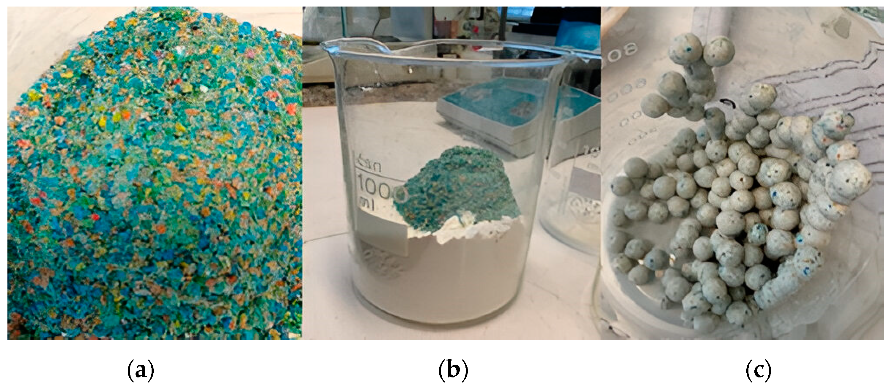
  • As it has already been proven that the kaolin has zeolitization capacity [21], it has been used as a main component in mixtures with different proportions of plastic, namely 0, 5, 10, and 20 wt.% of powdered MPF (Figure 1b), in order to check how it affects the manufacturing process of zeolitic lightweight aggregates (ZLAs).
  • Secondly, knowing the results obtained in the first stage, the kaolin was mixed with the rejected Mg-clay in proportions 1:0, 2:1, 1:2, and 0:1, thus covering 100%, 33%, 67%, and 0% of each clay in the mixture. A fixed percentage of MPF (in this case 10 wt.%) was added to the resulting clay mixture based on the results of the first stage of the investigation, something that will be discussed later.
The mixing process began with dry homogenization of each of the mixtures for several minutes by vigorous shaking inside a bag. A portion of each mixture was taken and the PL [22] was determined, from which the optimal moisture content (WOP) for subsequent granulation was determined as WOP = PL × 1.234 [21,23]. Based on the WOP results, the different percentages of MPF in the mixtures with kaolin did not significantly affect the amount of water to be added, which in this case ranged between 31 and 36%. On the contrary, the increase in the rejected Mg-clay compared to kaolin in the second stage did lead to a very noticeable increase in the water added to the mixtures, giving the following values: 34, 40, 54, and 100%. This is because the rejected Mg-clay has a very high PL due to its sepiolite content (Table 1). The homogeneous dough obtained after mixing with water passed to the granulation stage.

2.3. Granulation and Firing

Round granules of ~10 mm in diameter were manually formed from the wet dough (Figure 1c). They were oven-dried for 24 h at 105 °C and then fired in a muffle. Simultaneous differential scanning calorimetry-thermogravimetric analysis tests (DSC-TGA) were used as a basis for determining the heating conditions in the muffle (Figure 2).
In the case of the mixtures from the first part of the study, the firing temperature was 600 °C. According to Figure 2, this temperature is sufficient for the total thermal decomposition of the MPF and for kaolinite to be activated in the form of amorphous meta-kaolinite by dehydroxylation [24]. However, regarding the addition of the rejected Mg-clay, the temperature was raised to 900 °C since preliminary tests showed that it did not have zeolitization capacity if fired at 600 °C. Thus, the application of 900 °C would ensure the complete destruction of sepiolite and smectite structures, although with a possible minor crystallization of other phases [24], as pointed out by the endothermic–exothermic peak system between 820 and 850 °C (Figure 2). In both cases, the muffle temperature was maintained for 1 h, previously applying a heating ramp of 30 °C/min. The resulting material was cooled by natural radiation inside the muffle.

2.4. Hydrothermal Treatment

For each formulation, about 20 g of the fired granules were weighed and placed into a steel reactor with a Teflon vessel. Approx. 160 mL of 3M NaOH solution was added, corresponding to a liquid/solid ratio of exactly 8 mL/g. The reactor was properly closed and placed in an oven at 150 °C for 24 h. After taking it off the oven and once the temperature of the reactor dropped sufficiently for handling, the supernatant was removed, and the resulting material was washed with water until neutral pH. Finally, the resulting ZLA was dried in an oven at 105 °C for 24 h.

2.5. Characterization of the Aggregates

According to the characterization tests followed by Moreno-Maroto and Alonso-Azcárate [21], the size of the specimens before and after hydrothermal treatment was determined using a caliper. The volumetric variation was then determined. The crushing strength was tested individually [25,26] in 10 specimens using a Nannetti® FM 96 press (Faenza, Italy), and the final result was calculated as the average of the ten data points.
Part of the fragments resulting from the crushing test were ground to <53 µm with an agate mill. The resulting powder was used to determine the real density (ρR) with an AccuPyc 1330 helium pycnometer (Micromeritics, Norcross, GA, USA). This powder material was also used to quantify the mineralogical composition by X-ray diffraction (XRD) with Rietveld refinement. NIST® SRM® 676a alumina standard (Gaithersburg, MD, USA) was used to quantify the amorphous phase. The equipment and conditions used were: PANalytical® diffractometer X’Pert Pro model (Malvern, UK); 45 kV, 40 mA, CuKα radiation, and a system of slits (soller–mask–divergence–antiscatter) of 0.04 rad–10 mm–1/8°–1/2°, with an X’celerator detector and Bragg–Brentano HD module. Water absorption for 24 h (WA24) and particle density (ρrd) were determined with a water pycnometer according to the EN-1097-6 standard [27]. Based on the data obtained through this test and the ρR results, the total, open, and closed porosity (PT, PO, and PC) were calculated through the equations described by Moreno-Maroto and Alonso-Azcárate [21]. The interior of some selected ZLA samples was coated with Au using a Quorum Q150T S sputtering metallizer (Laughton, East Sussex, UK). Then, the ZLA microstructure was observed by scanning electron microscopy (SEM) with a Hitachi S-3000N instrument (Hitachinaka, Japan). The microscope operated under high vacuum conditions with an accelerating voltage of 20 keV, a lifetime of 40 s, a working distance of 14.7 to 17.4 mm, and a beam current of 300 mA. Secondary electrons were detected to accurately visualize surface and crystal morphology.

3. Results and Discussion

3.1. Zeolitic Lightweight Aggregates Obtained from Kaolin and Different Proportions of Marine Plastic

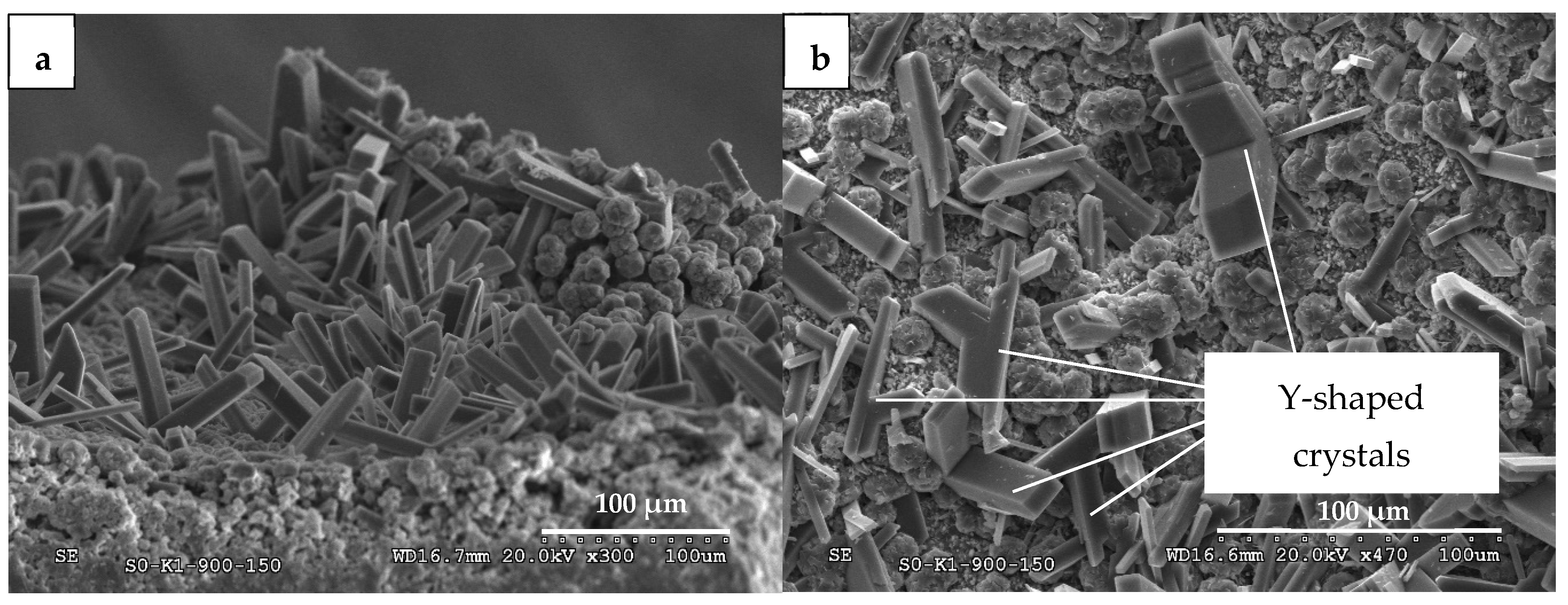
3.1.1. Mineralogical Changes and Zeolitization

The aggregates obtained for each formulation have been designated by the following code: K-xP-600, where K means kaolin, x is the % of MPF added, and 600 is the muffle firing temperature (in this case 600 °C). For hydrothermally treated samples (see specimens in Figure 3), the term H has been added to the end of the name (K-xP-600-H). It is worth noting that the high plastic content of the specimens containing 20 wt.% MPF led to the crumbling of the specimens after firing in the muffle, so that only the formulations with 0, 5, and 10 wt.% MPF could be studied.
The mineralogical changes that occurred during firing and hydrothermal treatment can be seen in Table 2 and Figure 4. The diffractograms are shown in Figure S1 in Supplementary Material. Firing at 600 °C affected the three formulations in a similar way, irrespective of the added MPF content. A very noticeable increase in the amorphization of the sample (82–87%) stands out, mainly associated with the dehydroxylation of kaolinite (endothermic peak with mass loss at ~ 525 °C for kaolin in Figure 2), which was reduced from 85% to 2–6%.
However, the hydrothermal treatment of the fired samples has affected the mineralogy in the opposite direction, highlighting a very notable decrease in such an amorphous phase in favor of the crystallization of minerals of the zeolite group (zeolite A, zeolite P1, and analcime) and feldspathoids (cancrinite, hydrosodalite, and nepheline). In the case of the feldspathoids detected, the International Zeolite Association integrates them into its zeolite database as they present a zeolite-type framework [28], so they will be considered as such in this study (Table 2).
The percentage of plastic added to the starting mixture is a variable that has significantly affected the mineralogy. From a general point of view, the overall zeolite content increases with the MPF content, going from 51.7% zeolite in the sample without plastic, to 58.3% in the sample with 5% MPF, and almost 80% in the materials with 10% plastic added initially (Table 2, Figure 4b). This would be because the pores left by the plastic particles when burning in the muffle would allow (1) a better permeation of the NaOH solution through the whole body of the specimen, and (2) more space for the nucleation and crystallization of the zeolites, both aspects leading to a more effective zeolitization [21]. Zeolite crystallization occurs mainly from the amorphous phase, whose content decreases proportionally with the increase in zeolite, although it is also nourished to a lesser extent by the remnants of kaolinite, illite, and quartz that had not amorphized during firing.
Regarding the mineral species neoformed in each sample during the hydrothermal treatment, according to Table 2 and Figure 4a, the presence of cancrinite and nepheline stands out (20 and 17%, respectively) in the sample without MPF, followed by zeolite A ( ~ 10%), with the rest of the zeolites presenting lower proportions. However, zeolite A ( ~ 20%) is the major mineral in the material to which 5 wt.% plastic was added, followed closely by nepheline ( ~ 17%), and to a lesser extent by hydrosodalite ( ~ 8%), cancrinite, and zeolite P1 (5–6%). However, in the material with 10 wt.% of MPF, no zeolite A has been detected, and as with the sample without plastic, its dominant mineral phases are cancrinite and nepheline (33% each), highlighting also in this case an abundant crystallization of analcime (10%).
Images taken by SEM have revealed that although crystal growth can occur throughout the body of the material (especially in the sample with 10% plastic, Figure 5a), it is most noticeable inside the pores (Figure 5b), which would be aligned with a higher zeolitization in the samples manufactured with MPF. Regarding the morphology of the neoformed minerals, aggregates of elongated crystals stand out in the three materials (Figure 5a–c). Most of them are flattened (Figure 5a–e), dominated by tabular and columnar habits and, to a lesser extent, acicular ones, characterized by a wedge-shaped end at {201} (Figure 5d), which is typical of nepheline [29,30]. Depending on the observed zones, these crystals can be found together with others of cancrinite, which can exhibit a needle habit with hexagonal prism geometry [31,32] (Figure 5b,c) or with rounded aggregate architecture [31] (Figure 5a). It is also remarkable the presence of analcime crystals with isometric trapezohedral morphology, namely of deltoidal icositetrahedron habit [33,34], especially in the samples to which plastic was added (Figure 5e,f). A common aspect between the sample without plastic and the one synthesized with 5 wt.% MPF is the appearance of cubic crystals (Figure 5g,h) of zeolite A [35,36] not present in the sample with 10 wt.% MPF, thus endorsing the XRD results (Table 2). These cubic crystals may be accompanied by other crystalline aggregates, such as the lepispheres (desert rose shape) shown in Figure 5h, which would be of hydrosodalite [37], although some authors have also reported them for the P1 zeolite [38,39]. Regarding the latter, the crystalline aggregates called by some authors as pinecone type or cactus type shown in Figure 5h,i, correspond to zeolite P1 [38,39,40], being most likely of the NaP1 type [38].

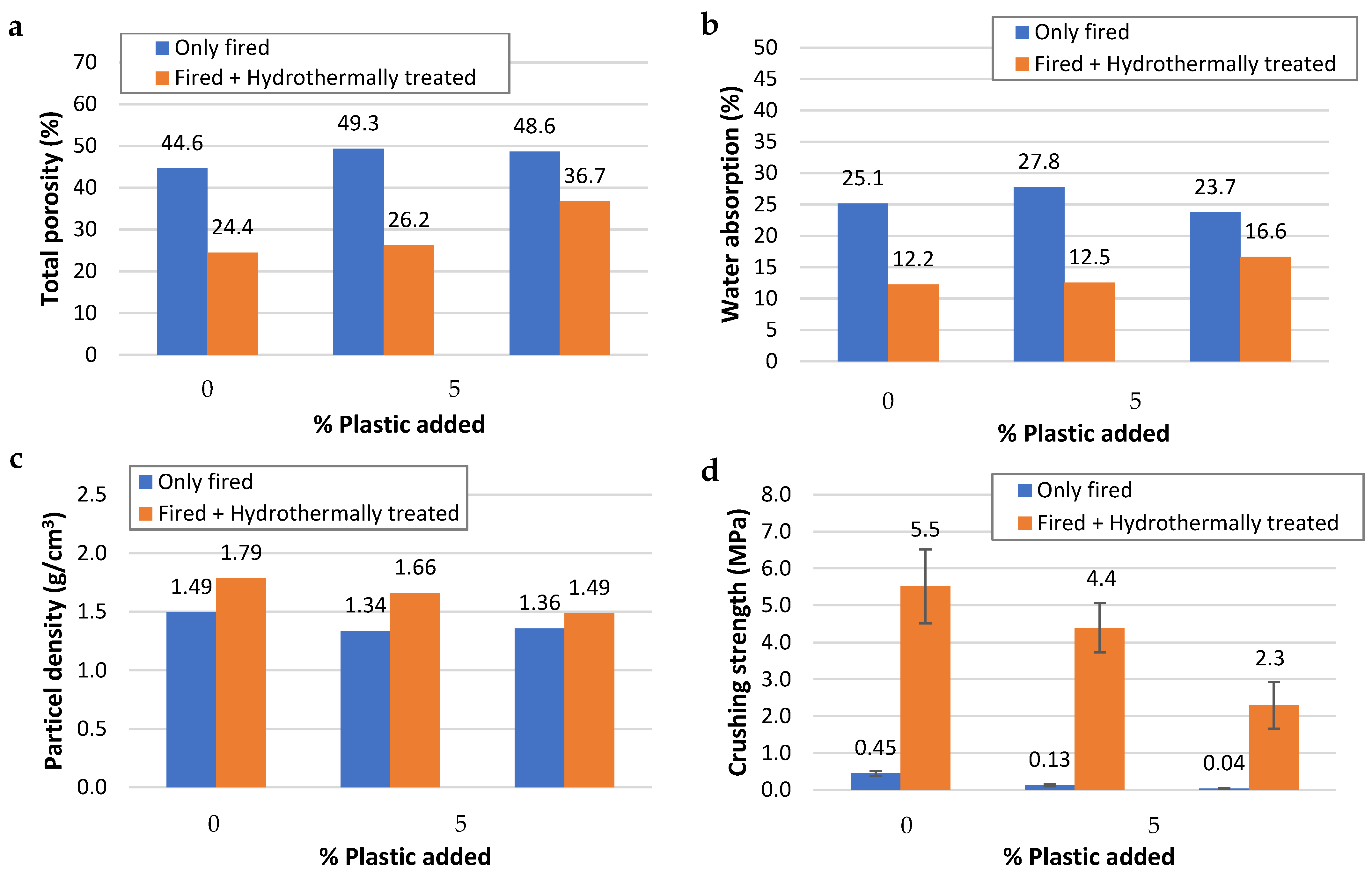
3.1.2. Technological Properties of the ZLAs

The main characteristics of the materials obtained are shown in Table 3. First, it can be seen that the average size of the fired aggregates is between 10.5 and 10.7 mm. The alkaline treatment did not result in a substantial change in the diameter of the specimens without MPF; however, it favored an increase of approx. 5% in the two samples with the additive. This could mean that the zeolite neoformation has meant a certain volumetric expansion in these samples (crystal growth in small pores and fissures may have “pushed” the internal structure), also promoted by the growth of microcrystalline crystals on the surface of the material.
As explained in the previous section, zeolitization has occurred most intensely inside the pores (Figure 5b). This has led to a drastic decrease in total porosity (Table 3 and Figure 6a), a phenomenon that has been more pronounced in the sample with 0 and 5 wt.% MPF, dropping from PT = 45 and 49% to PT = 24 and 26%, implying a decrease of 20–23 points, i.e., 45–47%, respectively. In the case of the sample with 10 wt.% added plastic, the addition of higher plastic content has helped cushion porosity depletion, so the total porosity has decreased 24.5%, from 48.6% to 36.7%. The open porosity is dominant in the fired samples, with values between 32% (sample with 10 wt.% MPF) and 37% (the other two), while the closed porosity increased 7, 12, and 16% with the addition of the plastic. Due to this dominance of open porosity over closed porosity, the former has been more affected by zeolitization, being reduced to values between 21 and 25%, while the closed pores represent between 3 and 12% after treatment, being the sample with 10 wt.% of MPF less affected (Table 3). The clogging of the open pores is reasonable since the alkaline solution would penetrate through it without difficulty, and the zeolites can crystallize on the walls of these pores and open fractures (Figure 5b). However, the decrease in the closed porosity is counter-intuitive, and could indicate that the alkaline treatment is capable of permeating a large part of the structure through the different physicochemical and mineralogical transformations that have taken place, even altering the walls of the closed pores, in which crystals could also have grown.
This decrease in porosity is critical, as it has affected the technological properties of the material. Thus, while the water absorption in the samples only fired was around 23–27%, this figure has been reduced after zeolitization to 12% and 17% in the samples with 0 and 5% MPF and 10% MPF, respectively, representing a variation over the non-treated specimens of more than −50% in the former two and almost −30% in the latter (Table 3, Figure 6b).
Regarding the density of the materials obtained, the decrease in porosity of the material has led to the ρrd values increasing between 10% and 24% compared to the fired material from which they come. Thus, in the sample without added plastic, the starting density was 1.49 g/cm3, which after the hydrothermal treatment rose to 1.79 g/cm3. In the case of samples with MPF, the density before zeolitization was ~ 1.35 g/cm3, increasing after it to 1.66 g/cm3 in materials with 5 wt.% of plastic added and somewhat less (1.49 g/cm3) in those with 10 wt.% MPF (Figure 6c). It is important to highlight that all values are below the limit of 2.00 g/cm3 established by the EN 13055-1 [41] standard, which means that the materials obtained could be used as lightweight aggregates.
Finally, an essential parameter is the mechanical strength, in this case measured as the crushing strength of single specimens. According to Figure 6d, several interpretations can be made. Firstly, the only-fired materials have a very low strength, between 0.04 and 0.45 MPa, and the addition of plastic tends to reduce it. However, this is corrected with a significant increase in the crushing strength after zeolitization, presenting values of 5.5, 4.4, and 2.3 MPa in the samples with 0, 5, and 10 wt.% MPF, respectively. This represents an increase ratio of 12, 34, and almost 58 times the strength of the starting fired material (Table 3), which allows lightweight materials with improved mechanical strength to be obtained, in this case zeolitic lightweight aggregates.
Beyond these technological improvements, the environmental impact generated by the burning of plastic waste is an aspect that will be evaluated in a future study. In the fight against plastic landfilling, the most widely used way to dispose of plastic waste in Europe is energy recovery (over recycling). This means that most of the plastic waste is already incinerated to obtain heat, electricity, or fuel, so there is a suitable and safe technology for this [42], which could be adapted to the manufacturing method presented in this work.

3.2. Effect of the Addition of the Rejected Mg-Clay (Rich in Smectite and Sepiolite) on the Zeolitization of Lightweight Aggregates

3.2.1. Mineralogical Changes and Zeolitization

The results of mineralogical composition corresponding to the materials obtained in the mixtures of rejected Mg-clay and kaolin are shown in Table 4. The diffractograms are shown in Figure S1 in Supplementary Material. Based on the findings of the first part of the study, it was decided to add an amount of 10 wt.% MPF to maximize the zeolitization of the samples. The formulations containing 67% and 100% rejected Mg-clay do not appear in Table 4, because the specimens obtained after the hydrothermal treatment tended to crumble in aqueous medium, so they were discarded.
Firing at 900 °C did not lead to significant changes in the mineralogy of the sample with 100% kaolin with respect to its counterpart fired at 600 °C, beyond the complete amorphization of the little kaolinite that remained (Table 2 and Table 4). In the case of the granules with 33% rejected Mg-clay, firing has led to the thermal decomposition of the calcite and dolomite of the starting mixture, as well as the destruction of all the phyllosilicates, with the exception of illite, although its content is very low ( ~ 2%). The initial feldspar and plagioclase content (4 and 8%, respectively) has also been reduced to ~ 1%. The decomposition of the original phases has led to a significant amorphization of the material (70%), as well as the neoformation of two new phases: pigeonite (4%) and mullite (13%). The DSC-TGA graphs in Figure 2 reveal that these new minerals would not come from kaolin since the peak of mullite formation is located at 1000 °C, which is higher than that applied. However, the endothermic–exothermic peak system between 800 and 850 °C in the rejected Mg-clay indicates, first, the structural decomposition of smectite and sepiolite and, subsequently, the crystallization of these two new phases [24].
Regarding the hydrothermal treatment, it has eliminated all the mineral species from the fired specimens, leaving only a few traces of quartz. The amorphous phase content was also reduced, more markedly in the sample with only kaolin (23% amorphous) than in the one containing 33% rejected Mg-clay (52%). This entails a different degree of zeolitization, being much more noticeable in the former (77% zeolite) than in the latter (48%). This suggests that the addition of the rejected Mg-clay (rich in magnesium smectite and sepiolite) could inhibit the zeolitization process under the conditions studied, which could explain why the formulations with 67% and 100% of this clay did not present structural stability. One possible reason for this is such a high Mg content (Table 1), so that for future research, an acid pretreatment could be considered to reduce its concentration.
Regarding the developed zeolite species, with respect to the sample with only kaolin, it can be seen that firing at 900 °C has led to slight changes, compared to the same formulation fired at 600 °C and then hydrothermally treated (Table 2 vs. Table 4). It stands out that cancrinite continues to be the dominant phase in the material fired at 900 °C (45.4% compared to 33.5% at 600 °C), followed by nepheline (11.8% compared to 33.2%). Likewise, no nepheline or hydrosodalite appears, but phillipsite (13%) and, to a lesser extent, sodalite (5%) and zeolite A (1.7%), which were not detected in the aggregate fired at 600 °C. This would indicate that the firing temperature could be a variable that can greatly affect the mineralogical changes during hydrothermal synthesis.
With regard to the zeolitic content of the material with rejected Mg-clay, the data in Table 4 reveal that, although the contents of cancrinite and zeolite A are very similar to those of the sample with only kaolin, sodalite would not have been formed. In the case of phillipsite and nepheline, their content would be lower than that of the aggregate with 100% kaolin (1.4% and 4.2%, respectively). Therefore, the addition of the rejected Mg-clay does not seem to have inhibited the crystallization of cancrinite (and to a certain extent neither of zeolite A), but it did so for the rest of the phases mentioned above.
The habit of the crystals presents parallels with several of those indicated previously in Figure 5. According to the SEM images in Figure 7, in many areas the only elongated crystals that can be observed are flattened, typical of nepheline (Figure 7), which contrasts with the fact that cancrinite is the dominant mineral in the two zeolitized samples (Table 4). This should be because cancrinite aggregates can also take other morphologies, such as the rounded ones [31] shown in Figure 7. Regarding nepheline crystals, some Y-shaped crystal associations have been observed (Figure 7b), something that also appears in the study of Lin et al. [30]. This type of structure is actually formed by the epitaxial growth of a butterfly twin, typical of nepheline [29], on another crystal of the same mineral.

3.2.2. Impact of the Rejected Mg-Clay on the Technological Properties of the ZLAs

The results in Table 5 show that the hydrothermal treatment has favored a slight increase in aggregate size (1–5%), agreeing with the results in Table 4 discussed above. In general terms, the sample containing only kaolin has very similar characteristics to those previously discussed for its counterpart fired at 600 °C, both for the fired sample and the hydrothermally treated sample. Therefore, the differences will not be discussed in detail. It simply needs to be noted that firing at 900 °C would have led to a higher degree of zeolitization of the sample, which has resulted in slightly less porosity and water absorption, as well as a slightly higher density and thus a strength also somewhat higher than those of the samples fired at 600 °C. Such differences could be explained by those shown above for the mineralogy of these samples.
Regarding the addition of 33 wt.% of rejected Mg-clay, the characteristics of the material obtained are very similar to those of the material produced with kaolin alone. In terms of density, the rejected Mg-clay has favored a slight increase in density (1.74 g/cm3 vs. 1.65 g/cm3). Despite this, it complies with the EN 13055-1 [41] standard for use as lightweight aggregate. For the rest of the properties, there are hardly any notable differences compared to its counterpart with only kaolin: water absorption of 11.5% compared to 11.8%; crushing strength slightly higher (3.4 MPa vs. 3.1 MPa); and total porosity of 27.4% versus 28.8%, representing a decrease in the porosity of the fired material of 45 and 41%, respectively. This decrease in porosity would affect both the open type (having a value of 20% with rejected Mg-clay and 19.5% without it) and the closed type (9.2% vs. 7.4%).
These results indicate that, although hydrothermal treatment in aggregates shaped with a high content of smectitic-sepiolitic magnesium clays would not lead to suitable zeolitic materials (at least with the conditions studied in this research), its addition in moderate proportions is promising, since materials with technological properties similar to those obtained only with kaolin could be produced.

4. Conclusions

A study is presented to sustainably develop innovative zeolitic lightweight aggregates (ZLAs), based on the protocol recently published by Moreno-Maroto and Alonso-Azcárate [21]. The main conclusions that can be drawn can be summarized as follows:
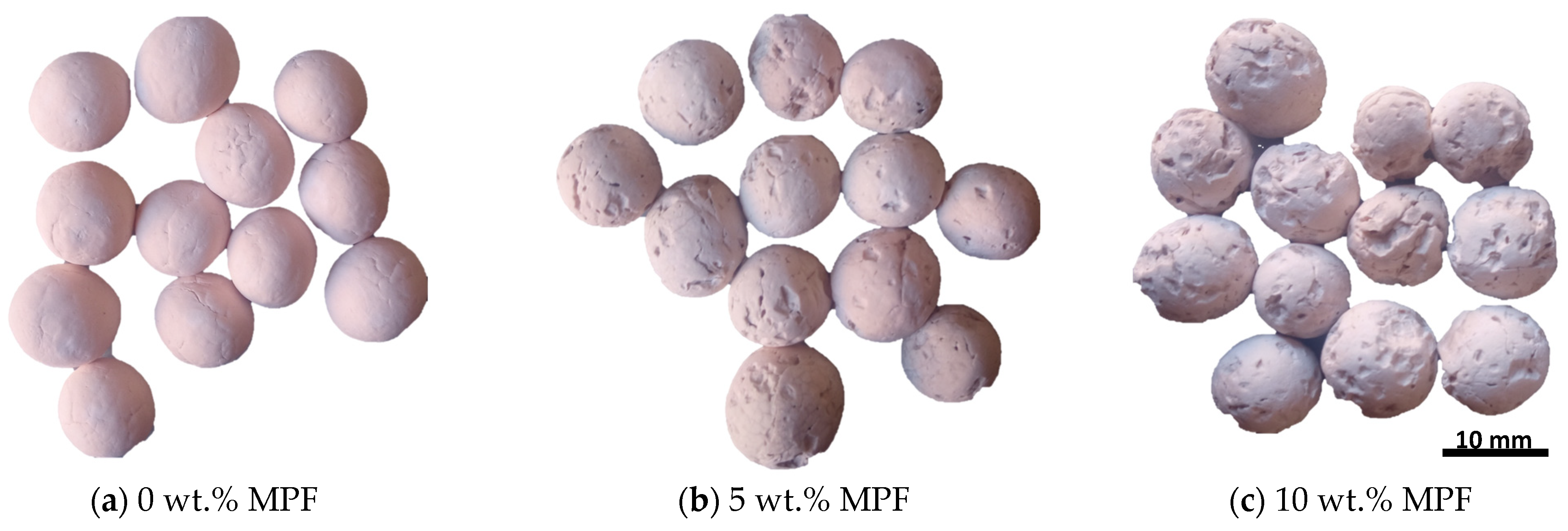
  • The incorporation of MPF in proportions not exceeding 10 wt.% would be positive since its combustion during firing favors the formation of open porosity, which makes the subsequent alkaline hydrothermal treatment more effective. Therefore, adjusting the percentage of MPF in the mixture could help control the final properties of the material obtained. Thus, although the mechanical strength decreases with the MPF, the lightness and degree of zeolitization improve.
  • The type of clay used in manufacturing is a critical aspect. Kaolin is very prone to zeolitization, being a suitable raw material for the manufacture of ZLAs. On the contrary, the rejected Mg-clay investigated (rich in magnesium smectite and sepiolite) seems to negatively affect zeolitization when it is added in high proportions. However, in a moderate content (33% rejected Mg-clay over 67% kaolin), it can give rise to materials with properties similar, or even superior (e.g., mechanical strength), to those obtained with kaolin alone. This invites further research into this clay with different formulation and manufacturing conditions, including the application of acid pretreatments for Mg removal.
  • The hydrothermal zeolitization method allows working at significantly lower firing temperatures (600–900 °C in this work) than those usual for lightweight aggregates (>1000 °C). This can provide an important economic and environmental advantage by reducing energy consumption during manufacturing. In any case, it will be necessary to investigate these aspects in more detail in the future (for example, through life cycle assessment), especially to check if the emissions linked to the combustion of the MPF are compensated by the energy savings during hydrothermal manufacturing.
  • The high zeolite content in the new lightweight aggregates could give them advanced properties compared to conventional ones. In addition to a significant increase in mechanical strength (even >50 fold compared to the starting fired material), it is well known the adsorbent capacity of zeolites, thus paving the way to investigate the decontamination capacity of the new ZLAs.
  • Despite the potential environmental advantages indicated above, the impact generated by the burning of plastic waste in the manufacturing process is an aspect to be evaluated (pending for another study). However, it should be noted that the most widely used way of disposing of plastic waste in Europe is energy recovery by incineration [42], which indicates that a viable and safe technology already exists, which could be adapted to the manufacturing method presented in this work.
Considering all of the above, the general conclusion is that the work presented here adapts to: (1) the concept of circularity, by incorporating waste in the manufacture, thus proposing new solutions to waste as problematic as plastics from marine litter; (2) sustainability and energy efficiency, by working at lower temperatures than usual; and (3) technological development, by obtaining zeolitic lightweight aggregates with promising properties compared to their conventional counterparts.

Supplementary Materials

The following are available online at https://www.mdpi.com/article/10.3390/app14177674/s1.

Author Contributions

J.M.M.-M. conceptualization, investigation, methodology, visualization, writing—original draft, writing—review and editing, funding acquisition, project administration, resources, supervision; J.M.G. and P.P. investigation; M.R., J.C., A.I.R. and R.F. writing—review and editing; J.A.-A. investigation, writing—review and editing. All authors have read and agreed to the published version of the manuscript.

Funding

This research was conducted as a part the project “Aplicación de residuos plásticos marinos como componentes tecnológicos en la fabricación de cerámicas zeolitizadas (OZEONIC)” framed within the 6th Edition of the Premios Mares Circulares (Circular Seas Awards) in its Research Projects 2023 modality, funded by Asociación Chelonia and promoted by Coca-Cola Europacific Partners.

Institutional Review Board Statement

Not applicable.

Informed Consent Statement

Not applicable.

Data Availability Statement

The data presented in this study are available on request from the corresponding author. The data are not publicly available due to privacy.

Acknowledgments

This research was conducted as a part the project “Aplicación de residuos plásticos marinos como componentes tecnológicos en la fabricación de cerámicas zeolitizadas (OZEONIC)” framed within the 6th Edition of the Premios Mares Circulares (Circular Seas Awards) in its Research Projects 2023 modality, funded by Asociación Chelonia and promoted by Coca-Cola Europacific Partners. Special thanks to Mares Circulares, Asociación Vertidos Cero and Centro Tecnológico AIMPLAS for providing the ground sample of marine plastic debris.

Conflicts of Interest

The authors declare no conflicts of interest.

References

  1. Fundación Conama. Decálogo Ciudadano Contra las Basuras Marinas; Ministerio para la Transición Ecológica, Ed.; Centro de Publicaciones: Madrid, Spain, 2016; Catálogo de Publicaciones de la Administración General del Estado, NIPO: 638-18-002-8. [Google Scholar]
  2. Zhang, Y.; Wu, P.; Xu, R.; Wang, X.; Lei, L.; Schartup, A.T.; Peng, Y.; Pang, Q.; Wang, X.; Mai, L.; et al. Plastic waste discharge to the global ocean constrained by seawater observations. Nat. Commun. 2023, 14, 1372. [Google Scholar] [CrossRef]
  3. Ministerio para la Transición Ecológica y el Reto Demográfico. Basuras Marinas. 2023. Available online: https://www.miteco.gob.es/es/costas/temas/proteccion-medio-marino/basuras-marinas.html (accessed on 11 October 2023).
  4. Cózar, A.; Sanz-Martín, M.; Martí, E.; González-Gordillo, J.I.; Ubeda, B.; Gálvez, J.A.; Irigoien, X.; Duarte, M. Plastic Accumulation in the Mediterranean Sea. PLoS ONE 2015, 10, e0121762. [Google Scholar] [CrossRef]
  5. Ministerio para la Transición Ecológica. Basuras Marinas; Catálogo Publicaciones de la Administración General de Estado: Madrid, Spain, 2016; NIPO: 013-18-097-2. [Google Scholar]
  6. Fu, Y.C.; Ho, M.L.; Wu, S.C.; Hsieh, H.S.; Wang, C.K. Porous bioceramic bead prepared by calcium phosphate with sodium alginate gel and PE powder. Mater. Sci. Eng. C 2008, 28, 1149–1158. [Google Scholar] [CrossRef]
  7. Vitale-Brovarone, C.; Verné, E.; Robiglio, L.; Martinasso, G.; Canuto, R.A.; Muzio, G. Biocompatible glass–ceramic materials for bone substitution. J. Mater. Sci. Mater. Med. 2008, 19, 471–478. [Google Scholar] [CrossRef]
  8. Kirschner, L.I. Lightweight Aggregate for Concrete and Method for Making Same. United States Patent No. 3992216, 16 November 1976. [Google Scholar]
  9. Malloy, R.; Kashi, M.G.; Swan, C.W. Fly Ash/Mixed Plastic Aggregate and Products Made Therefrom. United States Patent No. US6669773B2, 30 December 2003. [Google Scholar]
  10. Moreno-Maroto, J.M.; González-Corrochano, B.; Alonso-Azcárate, J.; Martínez García, C. A study on the valorization of a metallic ore mining tailing and its combination with polymeric wastes for lightweight aggregates production. J. Clean. Prod. 2019, 212, 997–1007. [Google Scholar] [CrossRef]
  11. Moreno-Maroto, J.M.; González-Corrochano, B.; Alonso-Azcárate, J.; Martínez García, C. Sintering of sepiolite-rich by-products for the manufacture of lightweight aggregates: Technological properties, thermal behavior and mineralogical changes. Mater. Construcción 2021, 71, e241. [Google Scholar] [CrossRef]
  12. Ramamurthy, K.; Harikrishnan, K.I. Influence of binders on properties of sintered fly ash aggregate. Cem. Concr. Compos. 2006, 28, 33–38. [Google Scholar] [CrossRef]
  13. Güneyisi, E.; Gesoglu, M.; Altan, I.; Öz, H.O. Utilization of cold bonded fly ash lightweight fine aggregates as a partial substitution of natural fine aggregate in self-compacting mortars. Constr. Build. Mater. 2015, 74, 9–16. [Google Scholar] [CrossRef]
  14. Nor, A.M.; Yahya, Z.; Abdullah, M.M.A.B.; Razak, R.A.; Ekaputri, J.J.; Faris, M.A.; Hamzah, H.N. A Review on the Manufacturing of Lightweight Aggregates Using Industrial By-Product. In Proceedings of the 2nd International Conference on Green Design and Manufacture 2016 (IConGDM 2016) MATEC Web of Conferences, Phuket, Thailand, 1–2 May 2016; Volume 78, p. 01067. [Google Scholar] [CrossRef]
  15. Mackenzie, K.J.; Welter, M. Geopolymer (aluminosilicate) composites: Synthesis, properties and applications. In Advances in Ceramic Matrix Composites; Woodhead Publishing: Cambridge, UK, 2014; pp. 445–470. [Google Scholar] [CrossRef]
  16. Peyne, J.; Gautron, J.; Doudeau, J.; Rossignol, S. Development of low temperature lightweight geopolymer aggregate, from industrial Waste, in comparison with high temperature processed aggregates. J. Clean. Prod. 2018, 189, 47–58. [Google Scholar] [CrossRef]
  17. Ayati, B.; Ferrándiz-Mas, V.; Newport, D.; Cheeseman, C. Use of clay in the manufacture of lightweight aggregate. Constr. Build. Mater. 2018, 162, 124–131. [Google Scholar] [CrossRef]
  18. Fawer, M.; Concannon, M.; Rieber, W. Life cycle inventories for the production of sodium silicates. Int. J. Life Cycle Assess. 1999, 4, 207–212. [Google Scholar] [CrossRef]
  19. AMI2030. Materials 2030 Manifesto: Systemic Approach of Advanced Materials for Prosperity—A 2030 Perspective. Advanced Materials Initiative 2030. 2022. Available online: https://www.ami2030.eu/wp-content/uploads/2022/06/advanced-materials-2030-manifesto-Published-on-7-Feb-2022.pdf (accessed on 7 February 2022).
  20. AMI2030. Materials 2030 Roadmap. Advanced Materials Initiative 2030. 2022. Available online: https://www.ami2030.eu/wp-content/uploads/2022/12/2022-12-09_Materials_2030_RoadMap_VF4.pdf (accessed on 7 February 2022).
  21. Moreno-Maroto, J.M.; Alonso-Azcárate, J. Hydrothermal zeolitization: Towards a paradigm shift for producing stronger and more sustainable construction materials. Constr. Build. Mater. 2024, 427, 136269. [Google Scholar] [CrossRef]
  22. ASTM D4318-10e1; Standard Test Methods for Liquid Limit, Plastic Limit, and Plasticity Index of Soils. Annual Book of ASTM Standards. ASTM International: West Conshohocken, PA, USA, 2017.
  23. Moreno-Maroto, J.M.; González-Corrochano, B.; Alonso-Azcárate, J.; Rodríguez, L.; Acosta, A. Development of lightweight aggregates from stone cutting sludge, plastic wastes and sepiolite rejections for agricultural and environmental purposes. J. Environ. Manag. 2017, 200, 229–242. [Google Scholar] [CrossRef] [PubMed]
  24. Földvári, M. Handbook of Thermogravimetric System of Minerals and Its Use in Geological Practice; Occasional Papers of the Geological Institute of Hungary; Geological Institute of Hungary: Budapest, Hungary, 2011; Volume 213, ISBN 978-963-671-288-4. [Google Scholar]
  25. Yashima, S.; Kanda, Y.; Sano, S. Relationship between particle size and fracture energy or impact velocity required to fracture as estimated from single particle crushing. Powder Technol. 1987, 51, 277–282. [Google Scholar] [CrossRef]
  26. Li, Y.; Wu, D.; Zhang, J.; Chang, L.; Fang, Z.; Shi, Y. Measurement and statistics of single pellet mechanical strength of differently shaped catalysts. Powder Technol. 2000, 113, 176–184. [Google Scholar] [CrossRef]
  27. EN 1097-6; Tests for Mechanical and Physical Properties of Aggregates—Part 6: Determination of Particle Density and Water Absorption. European Committee for Standardization: Brussels, Belgium, 2013.
  28. IZA. Database of Zeolite Structures. International Zeolite Association. 2024. Available online: https://europe.iza-structure.org/IZA-SC/ftc_table.php (accessed on 1 July 2024).
  29. Hansen, S.; Fälth, L. X-ray study of the nepheline hydrate I structure. Zeolites 1982, 2, 162–166. [Google Scholar] [CrossRef]
  30. Lin, D.-C.; Xu, X.-W.; Zuo, F.; Long, Y.-C. Crystallization of JBW, CAN, SOD and ABW type zeolite from transformation of meta-kaolin. Microporous Mesoporous Mater. 2004, 70, 63–70. [Google Scholar] [CrossRef]
  31. Deng, Y.; Flury, M.; Harsh, J.B.; Felmy, A.R.; Qafoku, O. Cancrinite and sodalite formation in the presence of cesium, potassium, magnesium, calcium and strontium in Hanford tank waste simulants. Appl. Geochem. 2006, 21, 2049–2063. [Google Scholar] [CrossRef]
  32. Selim, A.Q.; Mohamed, E.A.; Seliem, M.K.; Zayed, A.M. Synthesis of sole cancrinite phase from raw muscovite: Characterization and optimization. J. Alloys Compd. 2018, 762, 653–667. [Google Scholar] [CrossRef]
  33. Chen, X.; Qiao, M.; Xie, S.; Fan, K.; Zhou, W.; He, H. Self-Construction of Core−Shell and Hollow Zeolite Analcime Icositetrahedra:  A Reversed Crystal Growth Process via Oriented Aggregation of Nanocrystallites and Recrystallization from Surface to Core. J. Am. Chem. Soc. 2007, 129, 13305–13312. [Google Scholar] [CrossRef]
  34. Ma, X.; Yang, J.; Ma, H.; Liu, C.; Zhang, P. Synthesis and characterization of analcime using quartz syenite powder by alkali-hydrothermal treatment. Microporous Mesoporous Mater. 2015, 201, 134–140. [Google Scholar] [CrossRef]
  35. Jacas-Rodríguez, A.; Rodríguez-Pascual, P.; Franco-Manzano, D.; Contreras, L.; Polop, C.; Rodriguez, M.A. Mixed Matrix Membranes prepared from polysulfone and Linde Type A zeolite. Sci. Eng. Compos. Mater. 2020, 27, 236–244. [Google Scholar] [CrossRef]
  36. Campoverde, J.; Guaya, D. From Waste to Added-Value Product: Synthesis of Highly Crystalline LTA Zeolite from Ore Mining Tailings. Nanomaterials 2023, 13, 1295. [Google Scholar] [CrossRef]
  37. Zgureva, D.; Boycheva, S. Synthetic Zeolitic Ion-Exchangers from Coal Ash for Decontamination of Nuclear Wastewaters. Bulg. Nucl. Soc. Trans. 2015, 20, 132–136. [Google Scholar]
  38. Tang, Q.; Ge, Y.Y.; Wang, K.T.; He, Y.; Cui, X.M. Preparation of porous P-type zeolite spheres with suspension solidification method. Mater. Lett. 2015, 161, 558–560. [Google Scholar] [CrossRef]
  39. Zhou, Q.; Jiang, X.; Qiu, Q.; Zhao, Y.; Long, L. Synthesis of high-quality NaP1 zeolite from municipal solid waste incineration fly ash by microwave-assisted hydrothermal method and its adsorption capacity. Sci. Total Environ. 2023, 855, 158741. [Google Scholar] [CrossRef] [PubMed]
  40. Khodabandeh, S.; Davis, M.E. Zeolites P1 and L as precursors for the preparation of alkaline-earth zeolites. Microporous Mater. 1997, 12, 347–359. [Google Scholar] [CrossRef]
  41. EN 13055-1; Lightweight Aggregates. Part 1: Lightweight Aggregates for Concrete, Mortar and Grout. European Committee for Standardization: Brussels, Belgium, 2002.
  42. European Parliament. Plastic Waste and Recycling in the EU: Facts and Figures. 2024. Available online: https://www.europarl.europa.eu/topics/en/article/20181212STO21610/plastic-waste-and-recycling-in-the-eu-facts-and-figures (accessed on 11 August 2024).
Figure 1. (a) MPF powder used in the research; (b) MPF on kaolin before mixing; (c) wet pellets obtained by manual granulation.
Applsci 14 07674 g001
Figure 2. DSC-TGA plots of the raw materials used in this study. Heating ramp: 25 °C/min; atmosphere: air (clays). Equipment: SDT Q600 of TA Instruments (New Castle, DE, USA).
Applsci 14 07674 g002
Figure 3. Zeolitic lightweight aggregates obtained from kaolin and (a) 0 wt.%, (b) 5 wt.%, and (c) 10 wt.% of mixed plastic fraction from marine litter. The prints left by the burned plastic can be seen in (b) and especially in (c).
Applsci 14 07674 g003
Figure 4. Mineralogical composition of the kaolin and the lightweight aggregates obtained from it and different proportions of MPF (0P, 5P and 10P mean 0, 5, and 10 wt.% of MPF added): (a) Kao = kaolinite; Ill = illite; Q = quartz; Zeo A = zeolite A; Can = cancrinite; Hysod = hydrosodalite; Zeo P1 = zeolite P; Neph = nepheline; Ana = analcime; Am = amorphous phase. (b) Differentiation between zeolites, other minerals and amorphous phase.
Applsci 14 07674 g004
Figure 5. Images taken by SEM of zeolitized samples: (a) zeolite crystals along the entire section of sample K-10P-600-H, with rounded crystalline aggregates of cancrinite on the left and aggregates of elongated crystals of nepheline and cancrinite on the right; (b) elongated crystals of nepheline and cancrinite within a pore and (c) detail view of these in K-0P-600-H; (d) tip of an acicular crystal of cancrinite with hexagonal cross-section and tip of a nepheline crystal showing characteristic Miller indices according to Hansen and Fälth [29]; (e,f) analcime crystals with trapezohedral habit and, in (e) together with other nepheline tabular/columnars in K-5P-600-H; (g) cubic crystals of zeolite A in K-0P-600-H; (h) crystalline aggregate with cubic crystals zeolite A, pinecone aggregate of zeolite P1, and lepispheres of hydrosadalite or zeolite P1 in K-5P-600-H; (i) pinecone-like crystalline aggregate typical of zeolite P1 in K-10P-600-H.
Applsci 14 07674 g005
Figure 6. Technological characteristics of the zeolitic lightweight aggregates obtained from kaolin and different proportions of MPF: (a) total porosity; (b) water absorption; (c) particle density; (d) crushing strength.
Applsci 14 07674 g006
Figure 7. Images taken by SEM of zeolitized samples: (a,b) tabular and columnar crystals of nepheline and rounded aggregates of cancrinite in S0K1-10P-900-H and, including a detail view in (b) of Y-shaped nepheline crystals by epitaxial growth of a butterfly twin on another crystal of the same mineral.
Applsci 14 07674 g007
Table 1. Characteristics of the clays under study.
ClayParticle Size (µm) aAtterberg Limits bCarbon (%) cChemical Composition (%) dMineralogy (%) e
d50MeanLLPLTotal (Org.)SiO2Al2O3Fe2O3K2OCaOMgOOthersLOIKaoSmSpIlQPgFpCalDol
Kaolin4.68.342.127.0̶50.9350.40.40.10.10.512.684.9̶̶̶̶̶̶̶̶2.512.6̶̶̶̶
Rejected Mg-clay18.516.4171.174.80.85 (0.44)54.27.22.01.62.021.91.39.8̶37.8303.911.14.37.92.62.4
METHODS: a: Laser diffraction: Beckman Coulter® LSTM 230 (Nyon, Switzerland); b: Casagrande cup for LL and rolling test for PL [22]; c: TOC-analyzer Shimadzu® TOC-VCSH (Duisburg, Germany); d: X-ray fluorescence: Thermo ARL ADVANT’XP Sequential XRF (Thermo Fisher Scientific, Waltham, MA, USA); e: X-ray diffraction (XRD) with Rietveld refinement (see test conditions in Section 2.5), where: Kao = kaolinite; Q = quartz; Pg = plagioclase; Fp = alkali feldspar; Il = Illite; Sm = smectite; Sp = sepiolite; Cal = calcite; Dol = dolomite.
Table 2. Mineralogical composition of the kaolin and the lightweight aggregates obtained from it and different proportions of MPF (0P, 5P, and 10P mean 0, 5, and 10 wt.% of MPF added). Letter H = hydrothermally treated.
SampleMineralogical Composition (%)
KaoIllQZeo A aCan abHysod abZeo P1 aNeph abAna aAmΣ Zeolite abΣ Other Minerals
Kaolin (unfired)84.92.512.6 100
K-0P-6006.02.69.2 82.2 17.8
K-5P-6002.21.99.2 86.7 13.3
K-10P-6002.11.99.8 86.2 13.8
K-0P-600-H 0.75.09.620.13.90.216.91.042.651.75.7
K-5P-600-H 0.43.120.55.98.45.216.81.538.358.33.5
K-10P-600-H 33.52.30.833.210.120.279.9
Kao = kaolinite; Ill = illite; Q = quartz; Zeo A = zeolite A; Can = cancrinite; Hysod = hydrosodalite; Zeo P1 = zeolite P; Neph = nepheline; Ana = analcime; Am = amorphous phase. a Minerals registered as zeolites in the database of the International Zeolite Association [28]. b Feldspathoid with zeolitic framework type [28].
Table 3. Properties of the lightweight aggregates obtained from kaolin and different proportions of MPF (0P, 5P, and 10P mean 0, 5, and 10 wt.% of MPF added). The letter H at the end of the name indicates that the fired aggregates have also undergone hydrothermal treatment.
AggregateDiameter (mm)Crushing Strength (MPa)Density (g/cm3)Water Absorption (%)Porosity (%)
MeanSt. Dv.Δ (%) aMeanSt. Dv.Δ Ratio aρrdρRΔ ρrd (%) aWA24Δ (%) aPTΔ PT (%) aPOPC
K-0P-60010.60.7 0.450.07 1.492.695 25.1 44.6 37.67.0
K-5P-60010.70.7 0.130.03 1.342.635 27.8 49.3 37.212.2
K-10P-60010.50.6 0.040.02 1.362.641 23.7 48.6 32.216.4
K-0P-600-H10.70.60.95.51.012.31.792.36519.712.2−51.424.4−45.221.92.6
K-5P-600-H11.20.84.74.40.733.81.662.24924.312.5−54.926.2−46.920.85.4
K-10P-600-H11.00.64.82.30.657.51.492.3489.516.6−29.836.7−24.524.811.9
a Variation in hydrothermal treatment over the same material only fired.
Table 4. Mineralogical composition of the kaolin, the rejected Mg-clay and the lightweight aggregates obtained at 900 °C from kaolin and its mixture 1:2 with rejected Mg-clay (term S because of its high content in smectite and sepiolite) and 10 wt.% MPF (10P). Letter H = material hydrothermally treated after firing.
SampleMineralogical Composition (%)
KaoIllSmSpQPlagFpCalDolPigMuZeo A aCan abSod abPhi aNeph abAmΣ ZeoliteΣ Other Minerals
Kaolin (unfired)84.92.5 12.6 100
Rejected Mg-clay (unfired) 3.937.83011.14.37.92.62.4 100
S0K1-10P-900 c 3.2 12.2 84.7 15.4
S1K2-10P-900 c 1.7 9.11.40.7 3.813 70.3 29.7
S0K1-10P-900-H c 0.1 1.745.4513.111.822.8770.1
S1K2-10P-900-H c 0.2 1.540.9 1.44.251.8480.2
Kao = kaolinite; Ill = illite; Sm = smectite; Sp = sepiolite; Q = quartz; Plag = plagioclase; Fp = alkali feldspar; Cal = calcite; Dol = dolomite; Pig = pigeonite; Mu = mullite; Zeo A = zeolite A; Can = cancrinite; Sod = sodalite; Phi = phillipsite; Neph = nepheline; Am = amorphous phase. a Minerals registered as zeolites in the database of the International Zeolite Association [28]. b Feldspathoid with zeolitic framework type [28]. c The naming of the samples follows the same rule as that in Table 3, but in this case the proportion of rejected Mg-clay versus kaolin is distinguished with the term S for the former, which refers to its high content of smectite and sepiolite. Therefore, S0K1 indicates a 0:1 ratio (i.e., 100% kaolin) and S1:K2 a 1:2 ratio (33% rejected Mg-clay and 67% kaolin).
Table 5. Properties of the lightweight aggregates obtained from kaolin and its mixture 1:2 with rejected Mg-clay (term S because of its high content in smectite and sepiolite) and 10 wt.% MPF fired at 900 °C. The letter H at the end of the name indicates that the fired aggregates have also undergone hydrothermal treatment.
AggregateDiameter (mm)Crushing Strength (MPa)Density (g/cm3)Water Absorption (%)Porosity (%)
MeanSt. Dv.Δ (%) aMeanSt. Dv.Δ Ratio aρrdρRΔ ρrd (%) aWA24Δ (%) aPTΔ PT (%) aPOPC
S0K1-10P-90010.00.9 0.20.1 1.392.722 25.8 48.8 36.012.7
S1K2-10P-9009.50.6 1.70.4 1.442.859 24.1 49.7 34.815.0
S0K1-10P-900-H10.50.75.03.10.620.71.652.31218.111.8−54.128.8−41.019.59.2
S1K2-10P-900-H9.60.61.13.40.82.01.742.39521.111.5−52.427.4−45.020.07.4
a Variation in hydrothermal treatment over the same material only fired.
Disclaimer/Publisher’s Note: The statements, opinions and data contained in all publications are solely those of the individual author(s) and contributor(s) and not of MDPI and/or the editor(s). MDPI and/or the editor(s) disclaim responsibility for any injury to people or property resulting from any ideas, methods, instructions or products referred to in the content.

