Article

Numerical Investigation of Low-Velocity Ice Impact on a Composite Ship Hull Using an FEM/SPH Formulation

Department of Industrial Engineering, University of Bologna, via Fontanelle 40, 47121 Forlì, Italy
*
Author to whom correspondence should be addressed.
Appl. Sci. 2024, 14(17), 7679; https://doi.org/10.3390/app14177679
Submission received: 28 June 2024 / Revised: 27 July 2024 / Accepted: 21 August 2024 / Published: 30 August 2024
(This article belongs to the Special Issue Mathematical Methods and Simulations in Mechanics and Engineering)

Abstract

:
In cold climate regions, ships navigate through diverse ice conditions, making the varied interaction scenarios between hulls and ice critically important. It is crucial to consider the safety and integrity of the hull during an ice–hull interaction, especially in the presence of lightweight structures. Proper design and material selection can help improve the structure’s ability to withstand ice forces. Within the scope, understanding the behavior of ice and its interaction with the structure can inform the development of appropriate measures to minimize possible damage or failure. The current study focuses on the interactions occurring during the impact loading phases, which are characteristic of thin first-year ice. A sandwich structure made with carbon fiber-reinforced epoxy prepreg and PVC core was investigated. Low-velocity ice impact was modelled using the Ansys Workbench 2023 R2 and LS-DYNA R11 explicit solver. As the material model, the *MAT055 was chosen based on the literature, while ice was represented with its equation of state. The Tsai Wu criterion was adopted to identify tensile and compressive failure in the matrix and fibers. This simulation allowed us to evaluate how the composite material responds to ice impacts, considering factors such as the speed of the impact, the shape and thickness of the ice, and the properties of the composite material itself.

1. Introduction

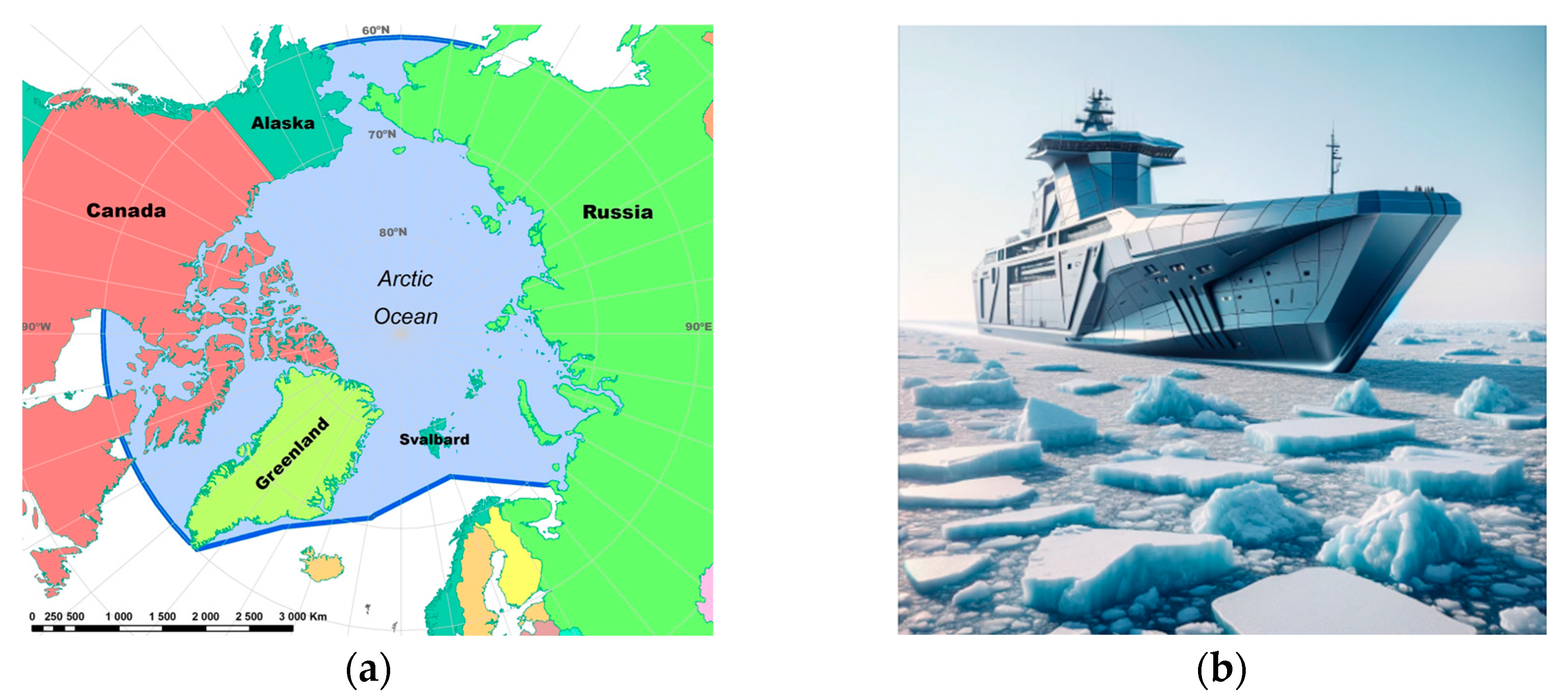
1.1. General Context

In recent years, the study of interactions between ships and ice in cold climate regions has garnered significant interest, driven by the upsurge in commercial activities in these zones. The ongoing effects of global warming, altering the landscape of the Arctic zone, underscore the imperative nature of grasping the intricate dynamics of navigating through ice-infested waters. The interplay between a vessel and ice is contingent on several variables: the nature and thickness of the ice, the vessel’s hull design, and its operational speed [1]. Research highlights that varying ice conditions present distinct challenges for maritime vessels. Comprehending these dynamics is vital for the safety and efficiency of nautical operations [1,2,3,4,5].
To address these challenges and enhance the safety of ships operating in polar waters, the International Maritime Organization (IMO) has developed the Polar Code [6]. The Polar Code provides guidelines and standards for ships operating in polar waters, aiming to ensure the safety of navigation and minimize the environmental impact in these sensitive regions.
To examine the impact of ice on ship structures, analytical methods employing mathematical models have been extensively used. These models elucidate the physical interactions during ship–ice encounters by considering factors like the ice’s strength and deformation attributes, integrated with the ship’s hull design [7].
Advancements in numerical simulation, particularly finite element analysis (FEA), have enhanced our ability to scrutinize ship–ice interactions under diverse conditions. This approach offers nuanced and thorough insights into these complex phenomena. By breaking down the ice and ship structures into smaller segments, these simulations reveal the dynamic responses of the hull to various ice loads [8,9,10,11,12].
In the assessment of the risks associated with these interactions, both deterministic and probabilistic methods have been employed. Deterministic strategies, exemplified by the Finnish–Swedish Ice Class Rules (FSICRs), rely on historical data and empirical evidence to formulate design criteria for ice-resistant ships [13]. However, these methods might not adequately account for the variability and uncertainties in ice conditions, particularly in areas affected by climate change [14,15]. Conversely, probabilistic methods, which consider the statistical distribution of environmental factors, offer a more thorough evaluation of the extreme load scenarios a ship might face [16,17]. By factoring in elements like ice density, thickness, and other environmental variables, these methods calculate the likelihood of surpassing different ice load thresholds (Figure 1). This approach fosters a more resilient and adaptable design strategy for vessels operating in ice-laden waters [13,14,15,16,17].
Simultaneously, it is important to acknowledge that modern vessels, including those intended for navigation in polar regions, are increasingly being constructed from materials other than metals, such as reinforced composites [18]. Fiber-reinforced plastic (FRP) plays a crucial role in meeting the requirements set forth by the Polar Code [19]. FRP materials, known for their lightweight and high-strength characteristics, are increasingly being incorporated into the construction of vessels that navigate polar waters. The use of FRP in shipbuilding enhances the overall structural integrity and resilience of the vessel, better equipping it to handle the challenges posed by ice-infested waters. Incorporating FRP into the construction of ships operating in polar regions aligns with the broader objectives of the Polar Code, emphasizing the importance of adopting materials and technologies that contribute to safe and sustainable navigation in these vulnerable ecosystems.
Given the burgeoning marine industry’s shift towards vessels with composite structures designed for icy conditions, and with the marine composites market projected to grow to 1.5 billion dollars from 2018 to 2024, this research becomes crucial. It aids in determining the extent to which composite materials can be effectively utilized in the marine sector.

1.2. Research Novelty

The current study focuses on investigating the performance of a sandwich structure made of carbon fiber epoxy prepreg and a PVC core under low-velocity impacts by ice wedges. The choice of materials aims to achieve a lightweight but stiff construction that can withstand the localized loads exerted by the ice. The use of smoothed particle hydrodynamic (SPH) modelling techniques, integrated with the finite element method (FEM), enables a detailed analysis of the ice impacts and the resulting response of the sandwich composite structure. This analysis was performed in line with previous investigations present in the literature [20,21,22,23]. By simulating the interactions between the ice and the composite materials, researchers can evaluate the structural integrity and performance of the sandwich structure under realistic ice load conditions. Overall, the application of SPH–FEM interaction to the present research aims to contribute to the development of standardized hull constructions and design guidelines that can enhance the safety and efficiency of vessels navigating through ice-covered waters. By improving our understanding of ship–ice interactions and exploring innovative materials and modeling techniques, we can mitigate the risks associated with ice impacts and ensure the resilience of ships operating in cold climate regions.
An innovative aspect of this research is its unique focus, as there are currently no published studies that explicitly explore the impact of ice on composite marine structures.

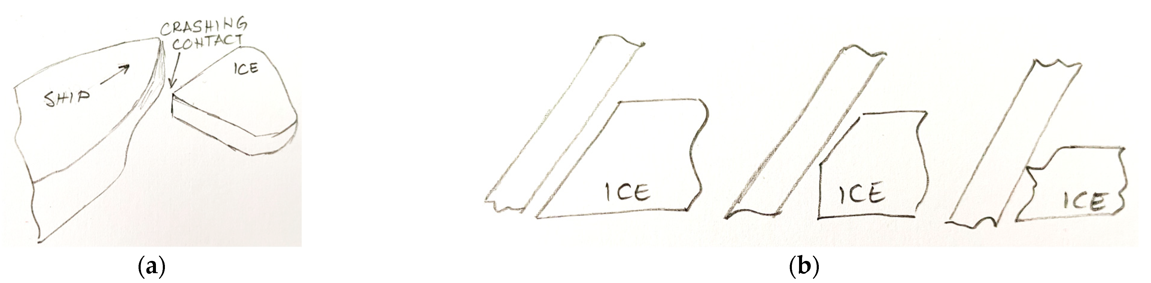
1.3. Ice Interaction

Ice–ship interaction refers to the dynamic interaction between a ship and ice when operating in icy waters (Figure 2a). It involves the forces and phenomena that occur as a vessel moves through or interacts with different types of ice, such as pack ice, brash ice, or ice floes [24,25]. When a ship encounters ice, various factors come into play that influence the interaction, such as:
  • Ice properties: The type and characteristics of the ice significantly impact the interaction. Factors such as ice thickness, ice concentration, ice strength, and ice temperature affect how the ice interacts with the ship;
  • Ship design: The design of the ship’s hull and ice-breaking capabilities play a crucial role in determining how the vessel interacts with the ice;
  • Ship speed and operation: The speed at which the ship moves through the ice affects the magnitude of ice loads and the resulting interaction;
  • Environmental conditions: The environmental conditions, including air temperature, water temperature, wind speed, and ice drift, can influence the ice–ship interaction.
During ice–ship interactions, various phenomena occur, including ice breaking, ice bending, ice crushing, ice loads on the hull, and vibrations induced by ice impacts. These interactions can exert significant forces on the ship, potentially leading to structural damage or changes in the ship’s behavior.
To categorize the impact conditions, in line with the literature [24,25,26], the schemes in Figure 2 can be considered. In Figure 2a, a crushing scenario is depicted where a vessel impacts a relatively thin ice sheet, while Figure 2b details possible contact patterns between the vessel’s keel and the ice surface. The ice surface was presented in three different geometry conditions, as it can be found in the real conditions, while the vessel keeps the same configuration. The three cases also demonstrate the evolution of the rules used when considering vessel–ice impact phenomena, progressing towards the consideration of increasingly focused areas.
Referring to the ice thickness, different authors proposed guidelines for dealing with ice conditions, categorized as young ice 1 and young ice 2 [27,28,29], as a practical method to relate to the most frequent conditions. These categories are based on the Bureau Veritas guidelines [28], which pertain to the design and structural requirements for vessels or structures operating in such ice conditions. In the young ice 1 environment, the maximum thickness of the ice is limited to 300 mm. This suggests that structures or vessels designed to operate in this environment should be able to withstand or navigate through ice thicknesses up to 30 cm. In the young ice 2 environment, the ice is defined in terms of its concentration and refers to the proportion of an area covered by ice compared to open water. In this case, young ice 2 would indicate an ice concentration lower than 3/10, meaning that less than 30% of the area is covered by ice.
The present investigation considers the case of young ice 1 and an impact area, as represented in the second scheme of Figure 2b.

1.4. Using Numerical Methods

When ice undergoes an impact or encounters significant external forces, it can experience large deformations, fractures, and fragmentation. Modelling this complex behaviour with the finite element method (FEM) can be challenging and inefficient due to several factors:
  • Large deformations: Ice can undergo substantial deformations under load, which can result in nonlinear behaviour. FEM typically relies on linear or moderately nonlinear assumptions, making it less suitable for accurately capturing the highly nonlinear response of ice under large deformations;
  • Fracture and failure: Ice is prone to fracturing and failure when subjected to high stress concentrations or sudden impacts. Modelling these fracture mechanisms within the FEM framework can be challenging, as it requires accurately representing the crack initiation, propagation, and interaction;
  • Fragmentation: Ice can fragment into smaller pieces during impact events, creating a complex system of multiple interacting bodies. Modelling this fragmentation process with FEM would require intricate meshing and tracking of individual ice fragments, which can be computationally demanding and impractical.
To address these challenges, researchers often explore alternative numerical methods specifically designed to handle large deformation, fracture, and fragmentation of materials. These methods may include:
5.
Discrete element method (DEM): This simulates the behaviour of individual discrete particles, making it suitable for modelling fragmentation and the interaction between ice fragments. It allows for tracking fractures and the realistic representation of ice behaviour during impact [30,31];
6.
Peridynamics: This is a non-local continuum method that explicitly accounts for crack initiation, propagation, and interaction. It can efficiently handle large deformations and fractures computationally, making it suitable for modelling ice behaviour during impact [32,33];
7.
Smoothed particle hydrodynamics (SPH): This is a meshless method, representing materials as particles. Initially developed as a probabilistic meshfree particle method for simulating astrophysical problems [34], SPH is well suited for simulating fluid behaviour and can accurately capture large deformations, fractures, and fragmentation without the need for complex meshing, as some research demonstrates [20,35,36,37,38,39,40].
These alternative numerical methods offer several advantages over traditional FEM when dealing with the complexities of large deformation, fracture, and fragmentation of ice. However, none have yet emerged as a definitive, leading approach, and researchers continue to explore and develop specialized techniques to improve the accuracy and efficiency of ice modelling under such conditions.
The SPH method is primarily used for hydrodynamic problems. When applied to solid materials, it shows advantages over grid-based numerical methods for large deformations. The spalling of ice, for instance, is an event that can be reproduced by an SPH simulation [41,42]. The spalling effect is particularly distinct for high velocity impacts. A typical application can be the hailstone impact on a structure.
There are different approaches for the numerical investigation of ice, yet there is no method that can be recognized as superior, universally applicable, and reliable. A full- scale simulation can be realized by the DEM which predefines the fracture points of the ice. The local effects and the exact physical material behavior can be described by the FEM, as it can rely on the most experience. Even though the impact of a hailstone has little in common with the natural crushing of sea ice, it demonstrates that the SPH method is preferably used for events connected to large distortions [41,42].
The current study positions itself within this vein of research, introducing a novel and relatively unexplored, yet promising approach. It introduces a hybrid model based on coupling FEM (finite element method) and SPH (smoothed particle hydrodynamics).
Accordingly, the continuum can be decomposed into a set of arbitrarily distributed particles with no connectivity (mesh-free). The integral representation method is adopted for field function approximation. The physical quantities of newly generated particles should be consistent with the corresponding finite elements [43]. The physical variable f ( x ) is a function of the three-dimensional vector x of newly generated SPH particles, which are determined by Equation (1).
f x = Ω f x W x x , h ) d x
where W ( x x , h ) is the smoothing Kernel function that depends on the distance between the studied point and the neighborhood particle, h is the smoothing length which defines the influence area of W. The smooth length of particles can be obtained according to the conservation of particles’ mass, as in Equation (2) [44,45].
h = ( 1 N e ) j N e r o j ( ρ o j ρ j ) 1 / 3
This hybrid approach, initially applied in entirely different contexts such as simulating bird strikes in aviation [46,47,48], has also gained popularity for investigating the interactions between ice and water or between ice and marine structures [49,50,51]. At the same time, there appears to be no existing research on the interaction of ice with composite structures using SPH–FEM coupling. Therefore, this work offers an entirely new perspective on the impact of ice on composite structures.

2. Materials and Methods

2.1. Ice Model Assessment

Model validation is imperative to guarantee the credibility and accuracy of numerical simulations. Considering this, we have chosen to validate the later proposed ice numerical model by replicating the only experimental procedures that were possible to find in the literature, outlined by the authors of article [52].
Two distinct simulations were conducted to validate the ice model. The first simulation treated ice as a rigid body, while the second utilized the SPH method, aligning with the approach adopted in our research. In terms of the ice model, we employed a long conical ice impactor (10J_Con) weighing 2.88 kg and measuring 115 mm in length, impacting the target specimen (100 × 100 mm) at a velocity of 2.64 m/s. The target specimen configuration was based on specifications outlined in the referenced article, comprising Divinycell PVC H100 (6.35 mm) and 0°/90° woven AS-4 carbon fiber/epoxy matrix as top and bottom face sheets (0.762 mm) [52].
Two diagrams (Figure 3—right part) from the article [52] were used to provide a brief comparison of the results (Figure 3—left part), the force–time diagram, and the highest peak force–time diagrams. The force–time diagram reveals that the rigid body (impact with steel adapter) generated a force of 1200 N, whereas in the simulation, we obtained a force of 1117 N. Similarly, the force–time diagram illustrates that the conical ice impact resulted in a peak force of 500 N, consistent with the numerical simulation utilizing the SPH ice model. The highest peak force–time diagrams further confirm that the highest force peak associated with the conical ice shape is approximately 500 N, mirroring the results obtained from the numerical simulation.
This comparison led us to the conclusion that the SPH model that we aimed to use in this research can represent the ice correctly.

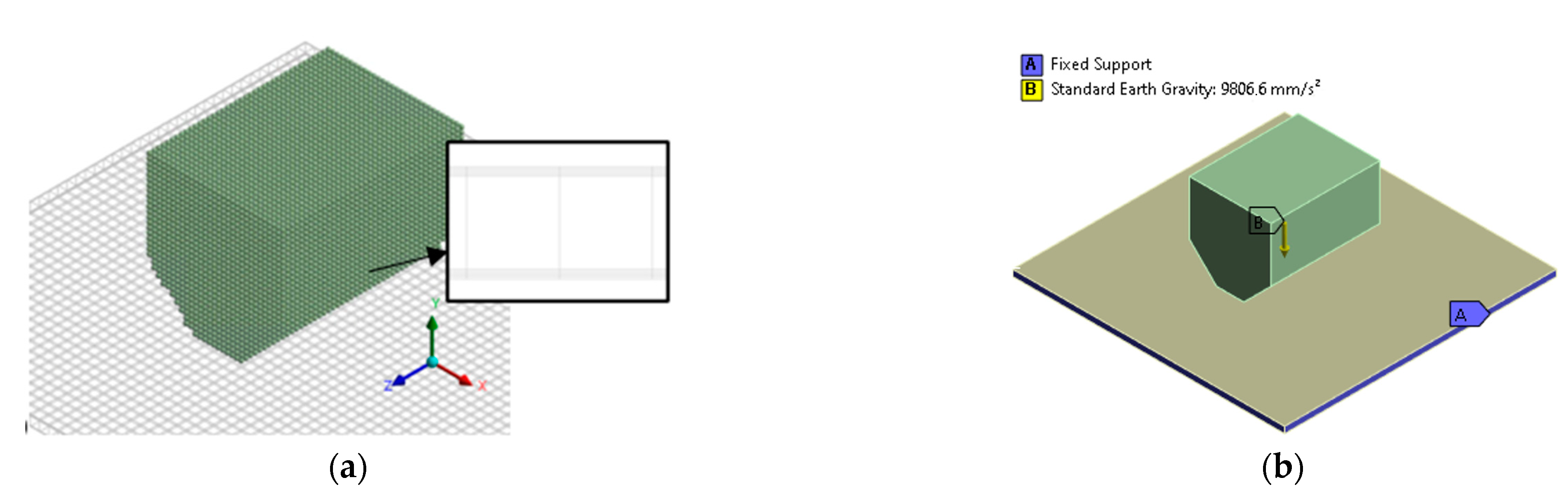
2.2. Geometry and Discretized Model

The present investigation is entirely in line with the expressed concepts in terms of the methodology, but it also proposes several elements of novelty.
The parameters for the velocity, mass, layer thickness, and other factors were selected in close collaboration with the commissioning company, which specializes in vessel production for ice navigation. These parameters were chosen based on their practical relevance and alignment with real-world conditions experienced by the company’s vessels. The velocity and mass represent typical operational scenarios, while the layer thickness reflects the standard design specifications for similar composite structures. This approach ensures that the model is both realistic and applicable to the actual engineering challenges faced in ice–ship interactions.
The geometry of a sandwich structure and an ice block is given in Figure 4. The sandwich structure, representing the boat hull, has a quadratic shape with dimensions of 500 × 500 mm and a total thickness of 12 mm (core with 10 mm and another 8 layers of 2 mm). On the other hand, the ice block has a specific geometry, as indicated in Figure 4, with a thickness of 200 mm (as predicted for young ice 1). This geometry was utilized in the numerical simulations to conduct drop tests on the sandwich structure. Two different masses of ice, 4 kg and 8 kg, were investigated.
The ice block has been discretized with the SPH method, as shown in Figure 5a. The diameter of each particle has been chosen as 5 mm to reduce the computational time. The sandwich structure has been discretized by a shell quadrilateral element, Figure 5a. The size was 10 mm to avoid penetration between the particles and structure. In both cases, explicit physical properties were selected during the Ansys LS-DYNA simulation.
The boundary conditions were set as fixed support on the four faces of the sandwich structure, indicated in blue in Figure 5b. Gravity and velocity of 5 m/s and 10 m/s were applied to the ice block in the Y direction. An impact velocity between 1–10 m/s is usually treated as low-velocity impact (LVI), while the ship–ice interaction occurs at a lower speed, for example 5 knots (2.6 m/s), which falls into the category of LVI [53,54,55,56].
The frictionless contact between the ice and the sandwich structure was defined as *CONTACT_AUTOMATIC_NODES_TO_SURFACE. The explicit Ansys LS-DYNA numerical simulation was performed in 8 ms.
Friction between the ice and the composite material was omitted in this study due to computational time constraints and natural friction reduction conditions, aligning with a comparative analysis of a similar experimental campaign [52] that also did not consider friction.

2.3. Material Model

The composite sandwich structure was arranged using the Ansys Workbanche 2023 R2 composite pre-processor (ACP Pre), a design material software that permitted the definition of the stratification layer per layer.
As constitutive materials, a unidirectional (U.D.) carbon epoxy prepreg of Toray Advanced Composites, Nijverdal, Netherlands (i.e., Toray T700 UD, Toray Advanced Composites, Nijverdal, The Netherlands) (Table 1) was preferred for the carbon fiber-reinforced composites (CFRPs), provided in 2 mm laminates, while a 10 mm PVC sheet was chosen as the sandwich core (Table 2). Four CFRP laminates were placed symmetrically above and below the core for a total of 8 layers. The staking sequence was [0, 45, 90, −45, core, −45, 90, 45, 0] as proposed in [53], to obtain a total thickness of 12 mm by 0.26 mm.
For the ice properties, a density of (ρ) of 900 kg·m−3, Young modulus (E) of 9 GPa, Poisson’sratio (ν) of 0.003, and a maximum principal stress criteria of 10 MPa [40] was used.
In LS-DYNA, the material “crushable foam” (*MAT63) was applied in the ice and PVC in compression simulations. Gagnon [41] was the first to introduce the foam analogue. Kim [42] took up the idea and implemented a failure criterion depending on the maximum principal stress. The ice characteristics were set by the volumetric strain–stress relationship.
In predicting damage initiation within laminated structures, lamina-level failure criteria are common despite their recognized limitations, such as homogenization assumptions, scale effects, anisotropy, multiaxial loading conditions, environmental effects, etc. These criteria usually combine with a degradation scheme that reduces the material properties once failure is initiated. Explicit finite element codes like LS-DYNA solve equations of motion using direct integration with explicit methods. LS-DYNA incorporates various material models (in the form of ‘MAT cards’) for modeling progressive failure and continuum damage mechanics. Some commonly used material models include MAT22, MAT54/55, MAT58, and MAT162 [42,57,58,59,60]. Each material model employs a distinct modeling strategy, including different failure criteria, degradation schemes, material properties, and a set of computation parameters that may not have an immediate physical interpretation. These material models offer flexibility for simulating material behavior under dynamic loading conditions.
ACP (Pre) was used to create the staking sequence, and the material model *MAT055 was preferred. *MAT055, known as enhanced composite damage, is commonly used in dynamic simulations to simulate damage progression. It requires less experimental input parameters compared to other damage mechanic-based material models (such as *MAT54, *MAT22 and others). *MAT055 predictions are based on the Tsai Wu failure criteria model, which is widely used in composite structure design and failure analysis due to its simplicity and accuracy [61,62,63]. This criterion provides a comprehensive framework for assessing failure by considering both the interaction between different types of stresses and the material’s strength properties in various loading conditions. Including an outline of this criterion offers clearer insights into how composite failure is evaluated and how it influences the impact analysis.
However, in the available literature, precise and comprehensive information on the input parameters for *MAT055 is limited. Existing articles often provide sparse and sometimes incompatible information. Even the Ansys LS-DYNA manual does not offer detailed definitions of the input parameters used for this material model.
Therefore, there is a need to evaluate the fundamental elastic behavior, failure initiation, and post-failure characteristics of *MAT055, as well as its suitability for modeling fabric composite material systems. More research and experimentation are required to establish appropriate guidelines and accurate input parameters for this material model to improve the reliability and accuracy of simulations involving fabric composite laminates.

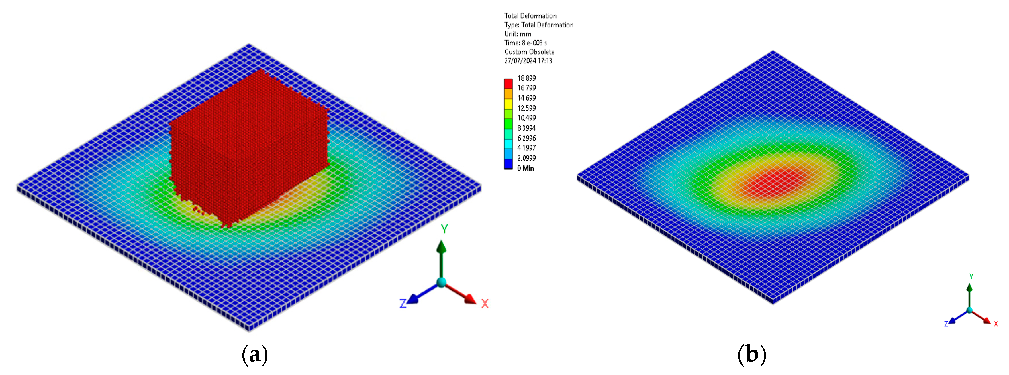
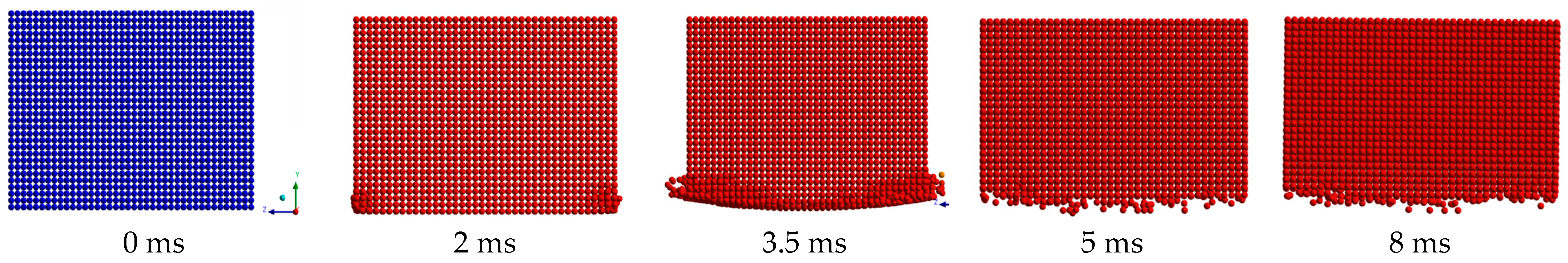
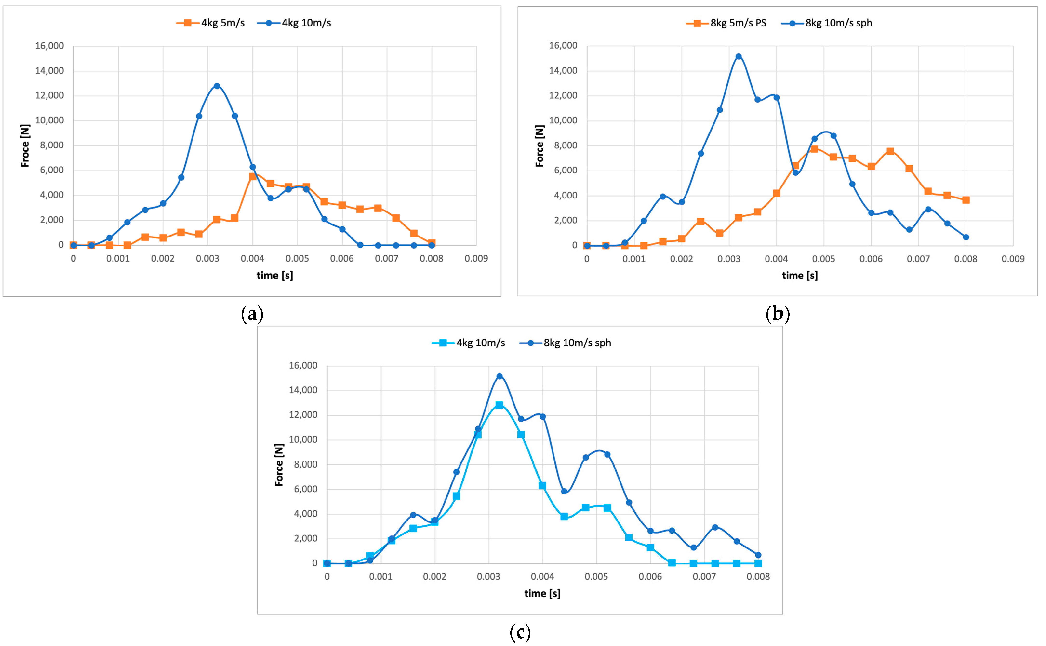
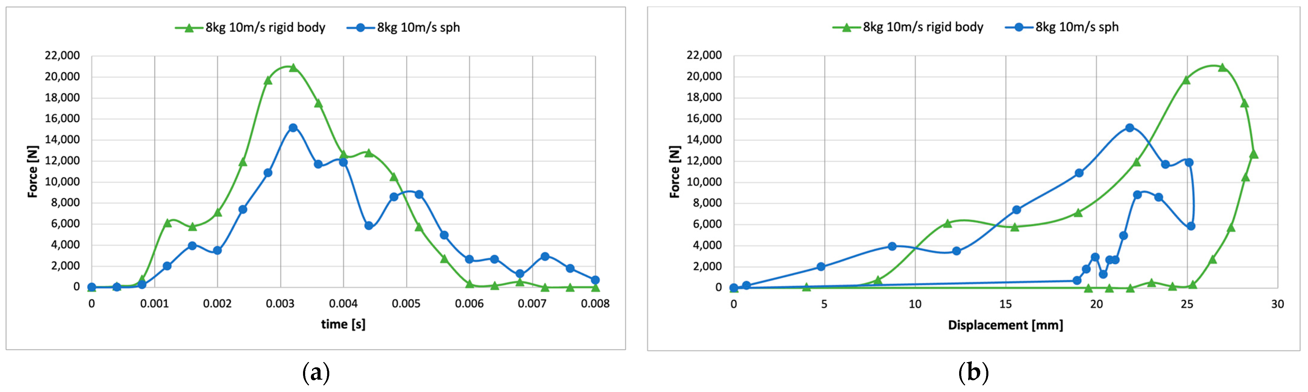
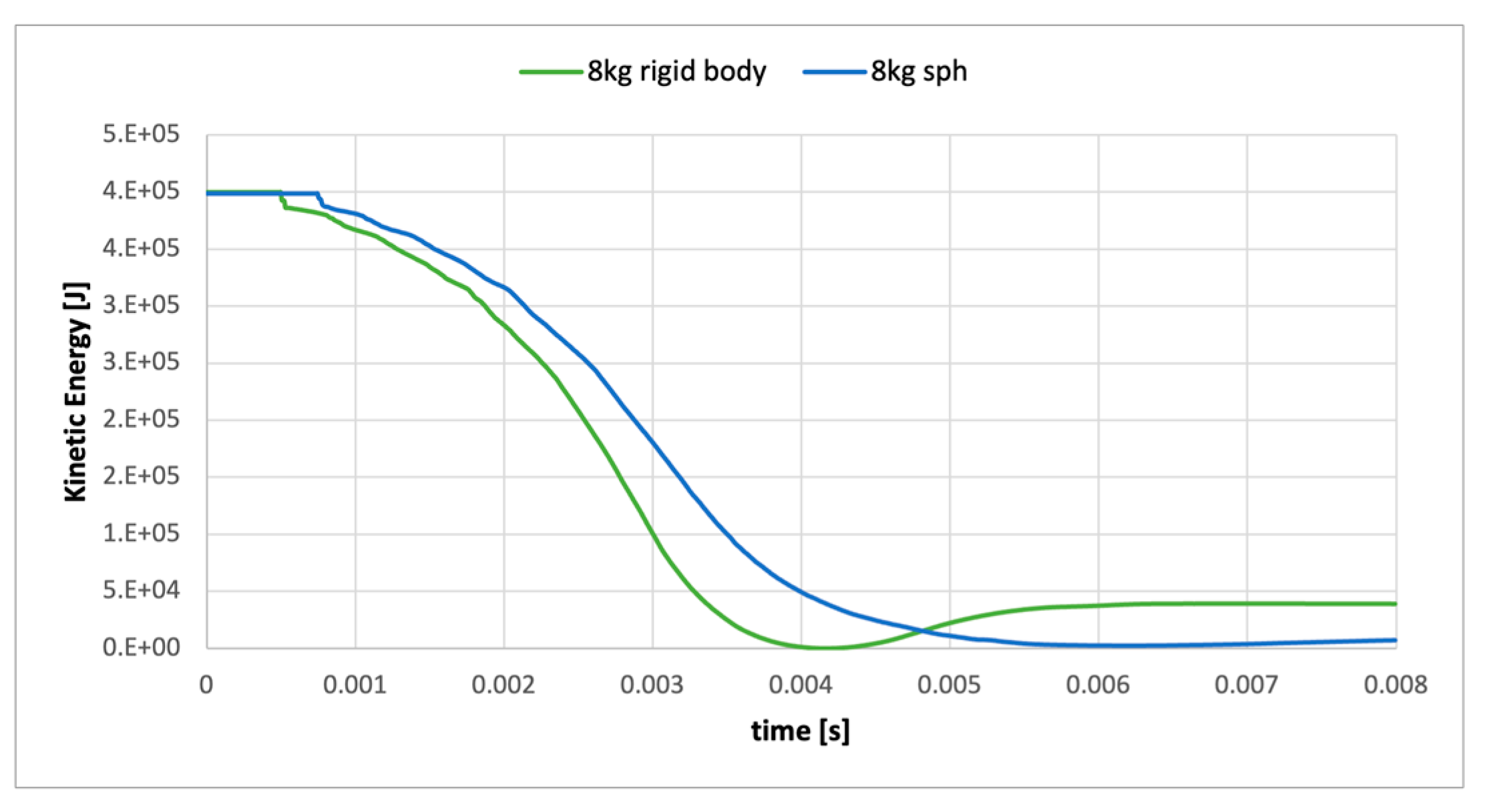
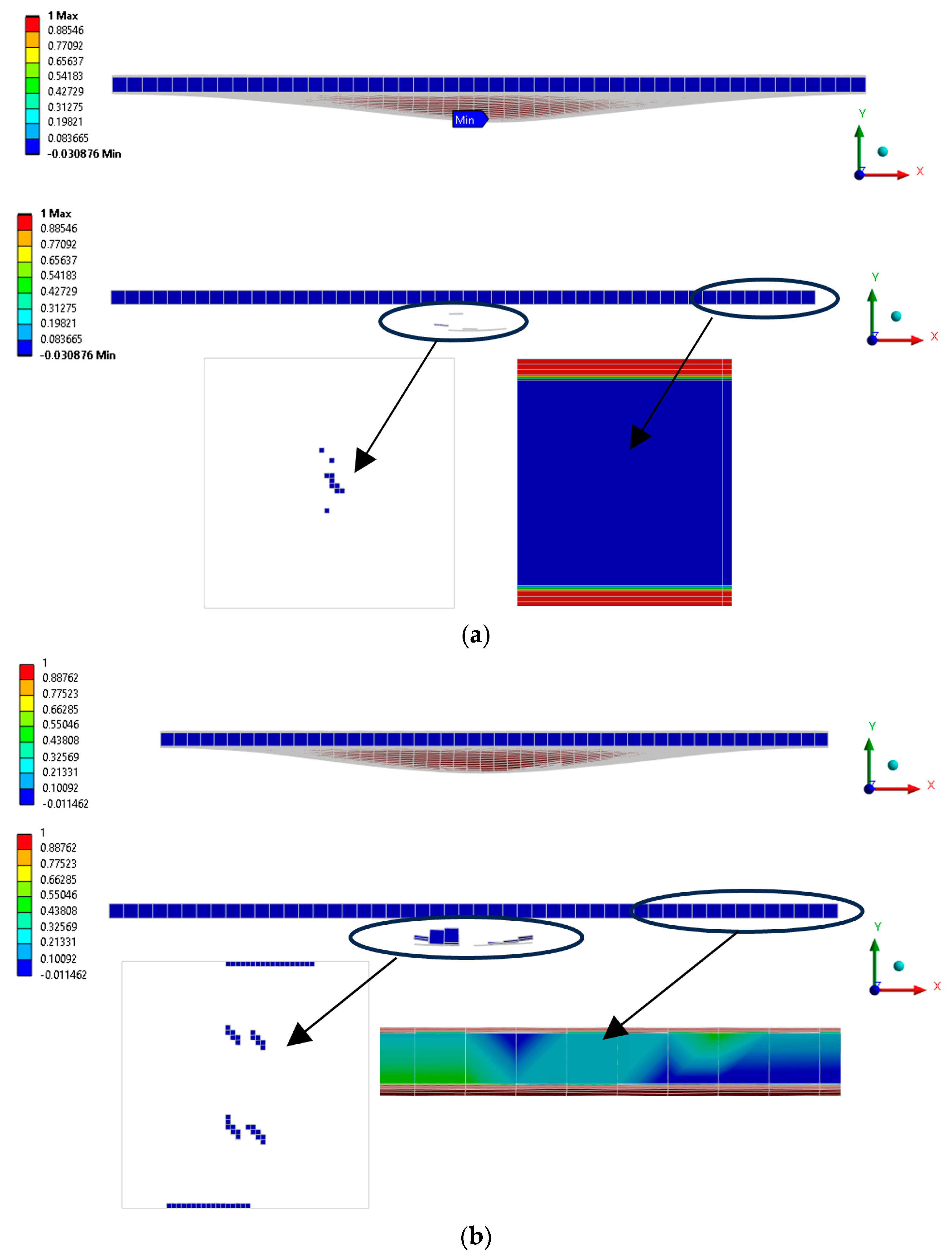
3. Results and Discussion

In this section, the SPH solver inside Ansys LS-DYNA is employed to study the low-velocity ice impact over the sandwich structure. The results obtained with the SPH–FEM approach were compared with the traditional impact of the rigid body on a composite plate. The model’s accuracy was investigated using the force–time, force–displacement, and energy–time curves. The calculation time was 8 ms, capable enough to capture all the effects during the impact. Generally, the impact starts with an elastic wave propagation from the impact point, where the propagation is influenced by the material damping and the attitude regarding energy diffusion. The response is governed by flexural and shear waves when the impact time becomes longer.
The results provided concern a scenario involving an 8 kg mass of ice traveling at a velocity of 10 m/s. In Figure 6a, the overall system’s total deformation is illustrated, revealing a noticeable ice impact. Contemporarily, Figure 6b illustrates the deformation, specifically in the Y-direction of 19 mm of the composite plate. On the other side, Figure 7 illustrates the degradation of the ice under identical impact conditions. The maximum principal stresses in the fiber directions of the composite plate are illustrated in Figure 8, while the shear stress can be observed in Figure 9.
The impact simulations involving 4 kg of ice revealed distinct variations in the impact energy when subjected to velocities of 5 m/s and 10 m/s. Notably, the impact forces ranged significantly, transitioning from 5.5 kN to 12.8 kN within a mere 1 ms of time difference in peak forces (Figure 10a). Similarly, for a heavier 8 kg piece of ice, the impact forces at 5 m/s were calculated to be 7 kN, whereas at 10 m/s, the force escalated to approximately 15 kN (Figure 10b). It is evident that higher impact velocities result in greater impact forces. The practical observation indicates that a velocity of 5 m/s was without a real peak of strength. Comparing the two different ices under the same impact velocity of 10 m/s, it can be observed that the pic is at the same time of 3.2 ms, with a difference in the impact force of 2 kN (Figure 10c).
The data obtained through the smoothed particle hydrodynamics (SPH) method for ice modeling were compared with results from a simulation where the ice was modeled as a rigid body. The higher impact forces observed in the rigid body simulation (Figure 11a) suggest a potential limitation of accurately capturing the internal deformations and interactions within the material. Additionally, Figure 11b illustrates that the rigid body simulation shows significantly greater displacement than the SPH simulation, indicating a potential oversimplification of the material’s behavior in the rigid body model.
The difference in the ice rebound between the rigid body simulations and SPH simulations (Figure 12) underscores the crucial role of accurately capturing the complex physical phenomena. Rigid body simulations, despite their computational efficiency, fail to account for the nuanced behavior of ice rebound that the SPH simulations capture, highlighting that computational cost alone does not justify the choice of rigid body models when precision is critical.
Composite materials, while they offer specific advantages, are inherently susceptible to impact damage due to their brittle nature. Upon impact, composites experience a range of failures including delamination, fiber breakage, matrix cracking, and potentially laminate perforation. The ability to absorb kinetic energy is pivotal to understanding damage; fiber failure generally absorbs a significant amount of energy, whereas matrix cracking and delamination absorb less. During low-velocity impacts, the kinetic energy is absorbed through elastic deformation, resulting in matrix cracking and delamination. In contrast, high-velocity impacts concentrate energy into localized regions, leading to severe and more focused damage. Accurate modeling of these impacts is essential for predicting how kinetic energy translates into structural damage, as failing to do so can lead to underestimations of potential damage and impact resistance.
With Ansys Workbench, post-processing of the results of composite analysis is typically performed using the composite pre-post (ACP) tool. ACP provides a dedicated environment for post-processing results related to composite materials. Unfortunately, the ACP post system cannot post-process all analysis types. Explicit analyses are not supported by ACP post because ACP’s post-processing system predicts a first ply failure and therefore does not consider damage or material degradation.
There are two composite strength models: enhanced composite damage and laminated composite fabric. For either of these two-material models, it is necessary to insert orthotropic elasticity, an orthotropic stress limit, and define the composite control tool (in the mechanical analysis settings) on enhanced composite damage, which is in line with *MAT54/55, or the laminated composite damage in line with the MAT48 material model. The results are written only for the top, bottom, and neutral axis.
In the case of enhanced composite damage, the outcomes are documented in the EPS definition. Typically, EPS represents equivalent plastic strain when applied to metal materials models. However, in the case of the enhanced composite damage material model, the result is expressed as a percentage of the intact layers. In the visual representation (refer to Figure 13), a value of zero means failure (illustrated in blue), while a value of 1 specifies an intact layer (illustrated in red). If we focus on the bottom layer, it provides the percentage of intact layers in the compressive fiber mode. The middle layer corresponds to the tensile fiber mode, and the top layer represents the tensile matrix mode. By selecting the unaverage display option, it is possible to examine a failure result for each finite element (Figure 13 details). The material model *MAT55 incorporates EPSF (damage initiation transverse shear strain) and EPSR (final rupture transverse shear strain) parameters, both of which are set with a value of zero. In practical terms, damage initiation occurs when the effective transverse shear strain reaches EPSF, while final rupture takes place when the effective transverse shear strain reaches EPSR.
Figure 13 illustrates the condition of each layer in the composite plate during the impact of an 8 kg ice mass traveling at a velocity of 10 m/s. Figure 13a provides an overview of the enhanced composite damage when utilizing the smoothed particle hydrodynamics (SPH) method for ice modeling, while Figure 13b presents the outcomes when the ice is modeled as a rigid body. Considering the similarity in the outcomes between the compressive and tensile fiber modes, as well as for the tensile matrix, the results are presented only for the bottom position to maintain brevity.
Upon analyzing Figure 13a, it becomes evident that the first three layers exhibit remarkable robustness across diverse mechanical scenarios, encompassing a compressive fiber, tensile fiber, and matrix in the tensile conditions. It is crucial to acknowledge that these initial layers are highly stable and unlikely to fail under various mechanical conditions. The fourth layer preserves 90% of its integrity in the area closer to the third layer, while reducing up to 50% when approaching the PVC area in the case of the compressive fiber, tensile fiber, and tensile matrix. In comparison, the PVC material demonstrates approximately 50% possible integrity under identical simulation conditions. In all three cases (bottom, middle and top), it is evident that some elements of the central part of the composite plate will reach final rapture. On the other side, Figure 13b reveals a distinctly divergent behavior, attributed to the representation of ice as a rigid body. A notable extent of damage is evident not only in the PVC, but also extends to the two adjacent layers. These findings confirm the appropriateness of modeling ice using the smoothed particle hydrodynamics (SPH) method.
Potential avenues for future research in the study of low-velocity ice impacts on sandwich structures encompass a range of advanced investigations and considerations. These include the exploration of sophisticated material models, examinations of multi-impact scenarios, validation studies through experimental research, analysis of dynamic loading conditions, and integration of thermal effects of ice–structure interactions. These future research directions should aim to deepen our understanding of the complexities involved in ice impacts on sandwich structures, providing insights for improved design methodologies and operational strategies in icy marine environments.

4. Conclusions

Various methods have been employed to study and understand ice–ship interactions, including physical model testing, numerical simulations, and analytical calculations. These approaches help to assess ice loads, analyze the ship’s structural response, and optimize ship design and operational strategies for safe and efficient navigation in icy waters. Ice–ship interaction is significant in polar regions and other areas with seasonal ice cover, where it is necessary to ensure the safety and reliability of maritime operations, such as shipping, resource exploration, and research expeditions.
The superiority of employing the SPH method over modeling ice as a rigid body for numerical simulations lies in its ability to capture the dynamic behavior of ice more accurately. SPH offers a finer-grained representation of the material, allowing for a more realistic simulation of complex phenomena, such as deformation, fragmentation, and fluid–structure interactions. Unlike the simplifications inherent in rigid body modeling, SPH provides a more nuanced and precise depiction of the ice’s response to various forces and conditions, making it a more suitable and robust approach for comprehensive numerical modeling.
In conclusion, the analysis of low-velocity ice impacts on sandwich structures using the SPH solver in Ansys LS-DYNA provided valuable insights. The study, focused on the force–displacement, force–time, and energy–time curves, demonstrated the model’s accuracy in simulating impact dynamics, capturing important phenomena like elastic wave propagation and the role of material damping in energy diffusion. The findings revealed a transition from elastic wave propagation to flexural and shear waves as the impact duration extended.
The material properties of ice and composites play a crucial role in determining the impact strength of the sandwich structure. For ice, properties such as density, compressive strength, and fracture toughness significantly influence the impact force and the extent of the damage inflicted on the composite structure. A higher density and compressive strength of ice generally result in higher impact forces, leading to more severe damage.
For composite materials, factors such as the fiber type, matrix material, and fiber–matrix bonding strength are critical. The high tensile and compressive strength of the composite fibers, combined with strong fiber–matrix bonding, enhance the overall impact resistance of the composite. Additionally, the energy absorption capability of the composite, determined by its toughness and ductility, plays a vital role in mitigating the damage during impact. Variations in these material properties can lead to significant differences in the impact response and damage mechanisms of the composite sandwich structure.
Considering these effects, it is important to select and characterize the material properties accurately to predict the impact behavior and ensure the reliability of the simulation results.
This research underscores the significance of understanding ice–structure interactions, particularly in polar regions and areas with seasonal ice cover. The implications extend to enhancing the safety and reliability of maritime operations, including shipping, resource exploration, and scientific expeditions. The study contributes noteworthy guidance for optimizing the sandwich structure design and operational strategies in ice-laden waters within the field of maritime engineering.
Future work could involve a detailed parametric study to quantify the sensitivity of impact strength to variations in the material properties of both ice and composite components.

Author Contributions

Conceptualization, G.M.; Software, A.P.; Validation, A.P.; Formal analysis, A.P.; Investigation, A.P.; Data curation, A.P.; Writing—original draft, A.P.; Visualization, A.P.; Supervision, G.M.; Project administration, G.M.; Funding acquisition, G.M. All authors have read and agreed to the published version of the manuscript.

Funding

Financed by the European Union—Next Generation EU (National Sustainable Mobility Center CN00000023, Italian Ministry of University and Research Decree n. 1033–17/06/2022, Spoke 11—Innovative Materials and Lightweighting). The opinions expressed are those of the authors only and should not be considered representative of the European Union or the European Commission’s official position. Neither the European Union nor the European Commission can be held responsible for them.

Institutional Review Board Statement

Not applicable.

Informed Consent Statement

Not applicable.

Data Availability Statement

Data are available on request.

Conflicts of Interest

The authors declare no conflicts of interest.

References

  1. Chandrasekaran, S. Ice Forces on Structures; Woodhead Publishing: Cambridge, UK, 2015; ISBN 978-0-08-100655-4. [Google Scholar]
  2. Jordaan, I.J.; Shepherd, I. Ship-Ice Interaction. In Encyclopedia of Ocean Sciences, 3rd ed.; Elsevier: Amsterdam, The Netherlands, 2009; pp. 611–620. [Google Scholar]
  3. Trochim, E.D. Ice Loads on Ships and Structures. In Encyclopedia of Hydrodynamics; National Research Council Canada: Ottawa, ON, Canada, 2008; pp. 1–12. [Google Scholar]
  4. Timco, G.W.; Frederking, R.M. Introduction to Ice Navigation and Ice Mechanics. In Practical Ice Navigation; Springer: Dordrecht, The Netherlands, 2013; pp. 1–19. ISBN 978-94-007-5773-3. [Google Scholar]
  5. Su, B.; Riska, K.; Moan, T. Numerical study of ice-induced loads on ship hulls. Mar. Struct. 2011, 24, 132–152. [Google Scholar] [CrossRef]
  6. Deggim, H. The international code for ships operating in polar waters (Polar Code). In Sustainable Shipping in a Changing Arctic; Springer: Berlin/Heidelberg, Germany, 2018; pp. 15–35. [Google Scholar]
  7. Timco, G.W.; Weeks, W.F. Ice Forces on Structures. In Sea Ice: An Introduction to Its Physics, Chemistry, Biology, and Geology; Wiley-Blackwell: Hoboken, NJ, USA, 2010; pp. 385–421. ISBN 978-1-4051-9632-0. [Google Scholar]
  8. Li, C.; Ehlers, S. Numerical Simulation of Ice-Induced Loads on Ships. Cold Reg. Sci. Technol. 2013, 96, 1–16. [Google Scholar] [CrossRef]
  9. Khedmati, M.R.; Jordaan, I.J. Analysis of Ice Forces on a Ship Using a Coupled Finite Element Model. Ocean. Eng. 2012, 49, 21–29. [Google Scholar] [CrossRef]
  10. Arntsen, A.; Jordaan, I.J. Ice-Induced Structural Loading on a Ship Hull-Comparison Between Model Tests and Numerical Analysis. Cold Reg. Sci. Technol. 2003, 37, 377–397. [Google Scholar]
  11. Brinkmann, P.; Lindqvist, P.A.; Elfving, A. A Numerical Analysis of Ice Loads on Ships Using a Simplified Ice-Ship Interaction Model. Cold Reg. Sci. Technol. 2012, 71, 91–100. [Google Scholar] [CrossRef]
  12. Frederking, R.M.; Jordaan, I.J. Numerical Analysis of Ice Forces on a Ship Hull. Cold Reg. Sci. Technol. 2002, 35, 67–85. [Google Scholar]
  13. Zhang, M.; Cheemakurthy, H.; Ehlers, S.; Polach, R.U.F.v.B.U.; Garme, K.; Burman, M. Ice pressure prediction based on the probabilistic method for ice-going vessels in inland waterways. In Proceedings of the ASME 2018 37th International Conference on Ocean, Offshore and Arctic Engineering, Madrid, Spain, 17–22 June 2018; Volume 8. [Google Scholar] [CrossRef]
  14. Matala, R. Investigation of model-scale brash ice properties. Ocean Eng. 2021, 225, 108539. [Google Scholar] [CrossRef]
  15. Lubbad, R.; Løset, S. A numerical model for real-time simulation of ship–ice interaction. Cold Reg. Sci. Technol. 2011, 65, 111–127. [Google Scholar] [CrossRef]
  16. Erceg, B.; Ralph, F.; Ehlers, S.; Jordaan, I. Structural Response of Ice-Going Ships Using a Probabilistic Design Load Method. In Proceedings of the ASME 2015 34th International Conference on Ocean, Offshore and Arctic Engineering, St. John’s, NL, Canada, 31 May–5 June 2015. [Google Scholar] [CrossRef]
  17. Daley, C.G.; Riska, K. Review of Ship-Ice Interaction Mechanics Report from Finnish-Canadian Joint Research Project No. 5 ‘Ship Interaction with Actual Ice Conditions’ Interim Report on Task 1A; Helsinki University of Technology: Espoo, Finland, 1990. [Google Scholar] [CrossRef]
  18. Rubino, F.; Nisticò, A.; Tucci, F.; Carlone, P. Marine application of fiber reinforced composites: A review. J. Mar. Sci. Eng. 2020, 8, 26. [Google Scholar] [CrossRef]
  19. Chalmers, D. Experience in design and production of FRP marine structures. Mar. Struct. 1991, 4, 93–115. [Google Scholar] [CrossRef]
  20. Zhang, Z.; Li, C.; Ehlers, S. Numerical Simulation of Ice-Structure Interaction Using Smoothed Particle Hydrodynamics. Ocean. Eng. 2015, 107, 1–12. [Google Scholar] [CrossRef]
  21. Vaziri, R.; Dalvand, M.; Mousavizadegan, S.H. A Smoothed Particle Hydrodynamics Model for Analysis of Ice Impact on Ship Structures. Cold Reg. Sci. Technol. 2014, 108, 52–63. [Google Scholar] [CrossRef]
  22. Khedmati, M.R.; Jordaan, I.J. Application of Smoothed Particle Hydrodynamics to Simulate Ice-Structure Interaction. Cold Reg. Sci. Technol. 2015, 118, 111–121. [Google Scholar] [CrossRef]
  23. Grabe, J.; Gjevik, B. Smoothed Particle Hydrodynamics Modelling of Ice-Structure Interaction. Cold Reg. Sci. Technol. 2013, 92, 24–33. [Google Scholar] [CrossRef]
  24. Kendrick, A.M. Polar Ship Design Standards–State of the Art, and Way Forward. Transactions 2014, 122, 428–433. [Google Scholar]
  25. Adams, J.M. Application of an Extended Inverse Method for the Determination of Ice-Induced Loads on Ships. Master’s thesis, Aalto University, Espoo, Finland, 2018. [Google Scholar]
  26. Kõrgesaar, M.; Kujala, P. Validation of the Preliminary Assessment Regarding the Operational Restrictions of Ships Ice-Strengthened in Accordance with the Finnish-Swedish Ice Classes When Sailing in Ice Conditions in Polar Waters; Aalto University: Espoo, Finland, 2017. [Google Scholar]
  27. Dudal, A.; Besse, P.; Yakimov, V.V.; Tryaskin, V.N. Numerical Tool for Basic Design Appraisal of Ice-Going Vessels. In Proceedings of the 109th Session of the Association Technique Maritime et Aéronautique—ATMA 2011, Paris, France, 23–24 May 2011. Bulletin de l’Association Technique Maritime et Aéronautique. [Google Scholar]
  28. Vermel, V.; Poulimenakos, K.; Cambos, P. A Method for Hull Scantlings Calculations for Ships Sailing in Low Salinity Waters. In Proceedings of the International Conference on Port and Ocean Engineering under Arctic Conditions, Trondheim, Norway, 14–18 June 2015. [Google Scholar]
  29. Bureau Veritas—Additional Class Notation Polar Class—Rules for the Classification of Polar Class Ships—February 2021. Available online: https://erules.veristar.com/dy/data/bv/pdf/527-NR_2021-01.pdf (accessed on 20 August 2024).
  30. Dorsk, A. Numerical Simulation of Sea Ice Dynamics with the Discrete Element Method; Internal report; Franklin W. Olin College of Engineering: Needham, MA, USA, 2006. [Google Scholar]
  31. Ji, S. Discrete element modelling of ice loads on ship and offshore structures. In Proceedings of the 7th International Conference on Discrete Element Methods; Springer: Singapore, 2017; pp. 45–54. [Google Scholar]
  32. Lu, W.; Li, M.; Vazic, B.; Oterkus, S.; Oterkus, E.; Wang, Q. Peridynamic modelling of fracture in polycrystalline ice. J. Mech. 2020, 36, 223–234. [Google Scholar] [CrossRef]
  33. Zhang, Y.; Tao, L.; Wang, C.; Sun, S. Peridynamic analysis of ice fragmentation under explosive loading on varied fracture toughness of ice with fully coupled thermos mechanics. J. Fluids Struct. 2022, 112, 103594. [Google Scholar] [CrossRef]
  34. Gingold, R.A.; Monaghan, J.J. Smoothed particle hydrodynamics: Theory and application to non-spherical stars. Mon. Not. R. Astron. Soc. 1977, 181, 375–389. [Google Scholar] [CrossRef]
  35. Zhang, N.; Zheng, X.; Ma, Q.; Hu, Z. A numerical study on ice failure process and ice-ship interactions by Smoothed Particle Hydrodynamics. Int. J. Nav. Arch. Ocean Eng. 2019, 11, 796–808. [Google Scholar] [CrossRef]
  36. Zhang, N.; Zheng, X.; Ma, Q. Updated smoothed particle hydrodynamics for simulating bending and compression failure progress of ice. Water 2017, 9, 882. [Google Scholar] [CrossRef]
  37. Pan, W.; Tartakovsky, A.; Monaghan, J. Smoothed particle hydrodynamics non-Newtonian model for ice-sheet and ice-shelf dynamics. J. Comput. Phys. 2013, 242, 828–842. [Google Scholar] [CrossRef]
  38. Crespo, A.J.C. Application of the Smoothed Particle Hydrodynamics Model SPH Physics to Free-Surface Hydrodynamics. Ph.D. Thesis, Departamento De Fisica Aplicada, Universidade De Vigo, Vigo, Spain, 2008. [Google Scholar]
  39. Fragassa, C.; Topalovic, M.; Pavlovic, A.; Vulovic, S. Dealing with the effect of air in fluid structure interaction by coupled SPH-FEM methods. Materials 2019, 12, 1162. [Google Scholar] [CrossRef] [PubMed]
  40. Pavlović, A.; Minak, G. FEM-SPH Numerical Simulation of Impact Loading on Floating Laminates. J. Mar. Sci. Eng. 2023, 11, 1590. [Google Scholar] [CrossRef]
  41. Gagnon, R. A numerical model of ice crushing using a foam analogue. Cold Reg. Sci. Technol. 2011, 65, 335–350. [Google Scholar] [CrossRef]
  42. Kim, H. Simulation of compressive ‘cone-shaped’ ice specimen experiments using LS-DYNA. In Proceedings of the 13th International LS-DYNA Users Conference, Dearborn, MI, USA, 8–10 June 2014. [Google Scholar]
  43. Zhang, A.; Yang, W.; Huang, C.; Ming, F. Numerical simulation of column charge underwater explosion based on SPH and BEM combination. Comput. Fluids 2013, 71, 169–178. [Google Scholar] [CrossRef]
  44. Zhang, Z.; Qiang, H.; Fu, X.; Xia, W. A 7.62 mm Rifle Bullet Impacting on a 30CrMnSiA Steel Target Plate: SPH-FEM Conversion Algorithm. Chin. J. Comput. Phys. 2012, 29, 73–81. [Google Scholar]
  45. Zhang, Z.; Qiang, H.; Gao, W. Conversion of 3D Distorted Finite Elements into SPH Particles During Impact Dynamic Deformation. J. Xi’an Jiaotong Univ. 2011, 45, 105–110. [Google Scholar]
  46. McCarthy, M.A.; Xiao, J.R.; McCarthy, C.T.; Kamoulakos, A.; Ramos, J.; Gallard, J.P.; Melito, V. Modelling of bird strike on an aircraft wing leading edge made from fibre metal laminates—Part 2: Modelling of impact with SPH bird model. Appl. Compos. Mater. 2004, 11, 317–340. [Google Scholar] [CrossRef]
  47. Zhou, Y.; Sun, Y.; Huang, T. SPH-FEM design of laminated plies under bird-strike impact. Aerospace 2019, 6, 112. [Google Scholar] [CrossRef]
  48. Zhou, Y.; Sun, Y.; Huang, T.; Cai, W. SPH-FEM simulation of impacted composite laminates with different layups. Aerosp. Sci. Technol. 2019, 95, 105469. [Google Scholar] [CrossRef]
  49. Ni, B.-Y.; Han, D.-F.; Di, S.-C.; Xue, Y.-Z. On the development of ice-water-structure interaction. J. Hydrodyn. 2020, 32, 629–652. [Google Scholar] [CrossRef]
  50. Jeon, S.; Kim, Y. Numerical simulation of level ice–structure interaction using damage-based erosion model. Ocean Eng. 2021, 220, 108485. [Google Scholar] [CrossRef]
  51. Chen, Z.; He, Y.; Gu, Y.; Su, B.; Ren, Y.; Liu, Y. A novel method for numerical simulation of the interaction between level ice and marine structures. J. Mar. Sci. Technol. 2021, 26, 1170–1183. [Google Scholar] [CrossRef]
  52. Banik, A.; Zhang, C.; Khan, M.H.; Wilson, M.; Tan, K.T. Low-velocity ice impact response and damage phenomena on steel and CFRP sandwich composite. Int. J. Impact Eng. 2022, 162, 104134. [Google Scholar] [CrossRef]
  53. Olsson, R. Mass criterion for wave controlled impact response of composite plates. Compos. Part A Appl. Sci. Manuf. 2000, 31, 879–887. [Google Scholar] [CrossRef]
  54. Pavlovic, A.; Fragassa, C. Numerical modelling of ballistic impacts on flexible protection curtains used as safety protection in woodworking. Proc. Inst. Mech. Eng. Part C J. Mech. Eng. Sci. 2017, 231, 44–58. [Google Scholar] [CrossRef]
  55. Pavlovic, A.; Fragassa, C. Analysis of flexible barriers used as safety protection in woodworking. Int. J. Qual. Res. 2016, 10, 71–88. [Google Scholar]
  56. Riska, K.; Uto, S.; Tuhkuri, J. Pressure distribution and response of multiplate panels under ice loading. Cold Reg. Sci. Technol. 2002, 34, 209–225. [Google Scholar] [CrossRef]
  57. Di Caprio, F.; Cristillo, D.; Saputo, S.; Guida, M.; Riccio, A. Crashworthiness of wing leading edges under bird impact event. Compos. Struct. 2019, 216, 39–52. [Google Scholar] [CrossRef]
  58. LS-DYNA Keyword User Manual Version 971; Livermore Software Technology Corporation: Livermore, CA, USA, 2007; Volume I.
  59. Song, Z.; Le, J.; Whisler, D.; Kim, H. Skin-stringer interface failure investigation of stringer-stiffened curved composite panels under hail ice impact. Int. J. Impact Eng. 2018, 122, 439–450. [Google Scholar] [CrossRef]
  60. Feraboli, P.; Wade, B.; Deleo, F.; Rassaian, M.; Higgins, M.; Byar, A. LS-DYNA MAT54 modeling of the axial crushing of a composite tape sinusoidal specimen. Compos. Part A Appl. Sci. Manuf. 2011, 42, 1809–1825. [Google Scholar] [CrossRef]
  61. Chen, X.; Sun, X.; Chen, P.; Wang, B.; Gu, J.; Wang, W.; Chai, Y.; Zhao, Y. Rationalized improvement of Tsai–Wu failure criterion considering different failure modes of composite materials. Compos. Struct. 2020, 256, 113120. [Google Scholar] [CrossRef]
  62. Feng, D.; Aymerich, F. Finite element modelling of damage induced by low-velocity impact on composite laminates. Compos. Struct. 2014, 108, 161–171. [Google Scholar] [CrossRef]
  63. Sutherland, L.S.; Soares, C.G. The use of quasi-static testing to obtain the low-velocity impact damage resistance of marine GRP laminates. Compos. Part B Eng. 2012, 43, 1459–1467. [Google Scholar] [CrossRef]
Figure 1. Area for ships operating in ice-covered waters (a) and visual representation of the problem under investigation of a vessel navigating through these polar regions (b).
Applsci 14 07679 g001
Figure 2. Impact on ice: (a) one potential scenario, (b) scheme of ice interaction with hull.
Applsci 14 07679 g002
Figure 3. Numerical validation of the SPH model in comparison with article [52].
Applsci 14 07679 g003
Figure 4. Geometry of sandwich structure (a) and ice block model (b).
Applsci 14 07679 g004
Figure 5. Details about the discretization method: (a) ice in particles (SPH) and sandwich in elements (FEM), (b) application of boundary and load conditions.
Applsci 14 07679 g005
Figure 6. (a) Total deformation, (b) direction deformation of the composite plate.
Applsci 14 07679 g006
Figure 7. Ice deformation during the LVI of 8 kg ice mass with velocity of 10 m/s.
Applsci 14 07679 g007
Figure 8. Maximum principal [MPa] stress in the function of layers.
Applsci 14 07679 g008
Figure 9. Shear stress [MPa] in the function of layers.
Applsci 14 07679 g009
Figure 10. Diagram of impact force vs. time: (a) 4 kg ic, (b) 8 kg ice with 5 m/s and 10 m/s, (c) 4 kg and 8 kg ice with 10 m/s.
Applsci 14 07679 g010
Figure 11. (a) Impact force vs. time. (b) Impact force vs displacement in the case of 8 kg ice, velocity of 10 m/s.
Applsci 14 07679 g011
Figure 12. Kinetic energy of rigid body and SPH ice model.
Applsci 14 07679 g012
Figure 13. Enhanced composite damage results: (a) SPH ice model, (b) rigid body ice model.
Applsci 14 07679 g013
Table 1. T700 UD orthotropic mechanical properties.
PropertySymbolLS-DYNA ParameterExperimental Value
Density ρ RO1.52 kg/m2
Young modulus (parallel to fibers)E1EA127 GPa
Young modulus (transverse to fibers)E2EB/EC8.41 GPa
Shear modulusG12GAB 4.21 GPa
Major Poisson’s ratio υ 12 /0.31
Minor Poisson’s ratio υ 21 PRBA0.02
Strength in 1-direction, tension F 1 t u XT2.20 GPa
Strength in 1-direction, compression F 1 c u XC1.47 GPa
Strength in 2-direction, tension F 2 t u YT48.9 MPa
Strength in 2-direction, compression F 2 c u YC199 MPa
Shear strength F 12 s u SC154 MPa
Table 2. PVC mechanical properties.
DensityYoung ModulusShear ModulusPoisson RatioTensile Ultimate StressCompressive Ultimate StressShear Strength
250 kg m−30.241 GPa0.105 GPa0.147.4 MPa6 MPa4.1 MPa
Disclaimer/Publisher’s Note: The statements, opinions and data contained in all publications are solely those of the individual author(s) and contributor(s) and not of MDPI and/or the editor(s). MDPI and/or the editor(s) disclaim responsibility for any injury to people or property resulting from any ideas, methods, instructions or products referred to in the content.

