Article

A Digital Twin System for Adaptive Aligning of Large Cylindrical Components

by
Wei Fan
1,2,3,*,†,
Ruoyao Xiao
1,†,
Jieru Zhang
4,
Linayu Zheng
1,2,3,* and
Jian Zhou
1
1
School of Mechanical Engineering and Automation, Beihang University, Beijing 100191, China
2
MIIT Key Laboratory of Intelligent Manufacturing Technology for Aeronautics Advanced Equipments, Ministry of Industry and Information Technology, Beijing 100191, China
3
Beijing Key Laboratory of Digital Design and Manufacturing Technology, Beijing 100191, China
4
Beijing Xinfeng Aerospace Equipment Co., Ltd., Beijing 100854, China
*
Authors to whom correspondence should be addressed.
These authors contributed equally to this work.
Appl. Sci. 2024, 14(18), 8307; https://doi.org/10.3390/app14188307
Submission received: 13 August 2024 / Revised: 5 September 2024 / Accepted: 13 September 2024 / Published: 14 September 2024

Abstract

:
Most large aerospace cylindrical components still adopt a manual aligning method with low automation, large manual intervention, and heavy dependence on operator workers, resulting in the low quality and efficiency of large component aligning, which seriously prolongs the manufacturing time of aerospace products. To cope with this issue, based on closed-loop adaptive control and digital twin (DT) technologies, an adaptive aligning system for large cylindrical components, i.e., the DT aligning system, is proposed in this study. For the DT aligning system, through the DT multi-dimensional modeling, i.e., geometric modeling, physical modeling, functional modeling, and data modeling, it can be divided into a physical space, a virtue space, and twin data. Note that the association, mapping, and interaction between physical space and virtual space of the aligning system can be realized via the twin data, thereby realizing real-time virtual display, monitoring, and control of the large component aligning. In addition, based on the measured pose data, aligning stress, and predicted aligning error, an adaptive force/position control method for large component aligning is proposed, and it can achieve real-time decision-making and precise execution of the aligning process. Finally, through application validation, the DT process system can realize the real-time status perception and process execution decision during the large component aligning. Finally, through experimental validation, it is found that the proposed system, i.e., the DT aligning system, can improve the quality and efficiency of the large aerospace cylindrical component aligning, as well as the automation and intelligent level of the aligning system.

1. Introduction

Typical aerospace products, such as rockets, satellites, and missiles are usually composed of several large, elongated cylindrical components (hereinafter referred to as large cylindrical components). The large cylindrical component has the characteristics of a large size and many types, and the production mode of “part assembly—final assembly” is often adopted for it. The part assembly stage is mainly to complete the assembly of large component parts, and the final assembly stage is mainly to complete the aligning assembly between the large cylindrical components. The aligning of these large cylindrical components is a critical procedure in the final assembly, testing, and experimentation stages of aerospace products, with stringent technical and safety requirements, which belongs to high-precision assembly, and is one of the core processes of aerospace manufacturing and also belongs to the small-batch multi-batch production process, and reflects the overall level of spacecraft manufacturing technology [1,2,3,4,5].
During the aligning process of large cylindrical components, it is necessary to align the axes of the aligning cylindrical component and the target cylindrical component using a posture adjustment platform and then apply axial force to achieve the aligning assembly of the two large cylindrical components. These components are positioned using pins and connected with bolts, requiring high positioning accuracy. Currently, most large cylindrical parts in aerospace products still use traditional aligning methods, where the target cylindrical component is fixed on a specific aligning platform, and the component to be assembled is manually moved to the target posture using rails. This method is realized based on analog quantity transfer; it can effectively reduce the internal aligning stress, but the assembly process requires the repeated adjustment of large cylindrical components, which results in a lengthy process that is labor-intensive with a low automation level, heavily relying on the operator’s experience and unable to ensure consistent aligning precision, leading to inefficiency [6,7]. Thus, traditional manual methods cannot meet the needs of the high-precision, high-efficiency, and highly reliable production of spacecraft, as well as the demand for mass production.
With the development of automation and digitalization technologies, automated aligning techniques have been introduced to complete the aligning process of large cylindrical components. Note that Figure 1 shows a typical automated aligning platform for large cylindrical components, which adopts a linear-guide-type CNC aligning platform as the aligning actuator, and its CNC docking platform has certain adjustment ability in six degrees of freedom, which can achieve the pose adjustment of large components in six degrees of freedom, as shown in Figure 1 [8]. In addition, advanced measurement technologies, such as laser tracking, 3D scanning, and visual measurement, combined with automated posture adjustment systems, enable the precise positioning and aligning of large cylindrical components [9,10,11]. However, during the automated aligning process, installation and motion transmission errors can reduce the aligning accuracy. Furthermore, there is still a lack of effective monitoring methods, preventing operators from perceiving real-time changes in the posture and assembly forces of the large cylindrical components, leading to an inability to effectively control the aligning quality, which may ultimately affect the overall performance and quality of aerospace products.
Digital twin (DT) technology [12,13,14] provides an effective solution to these problems. DT constructs a connection between physical entities and virtual models in a digital manner [15], simulating the characteristics, behaviors, processes, and performance of physical entities in the real environment through data interaction between the data model and the physical entity in the digital environment [16,17,18,19]. By leveraging virtual–physical interaction feedback, data fusion analysis, iterative decision optimization, and precise and efficient execution, DT integrates models, data, and intelligent technologies to enable reliable and effective analysis and decision-making in the production process [20,21].
Thus, this paper designs and develops a DT system for large cylindrical components in aerospace applications. This system fully incorporates the DT concept into the adaptive aligning of large cylindrical components, achieving dynamic aligning state monitoring and adaptive control of the aligning process, significantly improving the aligning quality and efficiency, as well as the automation and intelligence levels, of the aligning process for large cylindrical components, which can solve the quality and efficiency issues of large components in manual and automated aligning methods.

2. DT Aligning System for Cylindrical Components

2.1. Aligning System of Large Cylindrical Components

The DT aligning system of the large cylindrical component is composed of four subsystems, i.e., DT process system, control system, process sensing system, and physical execution system, as shown in Figure 2.
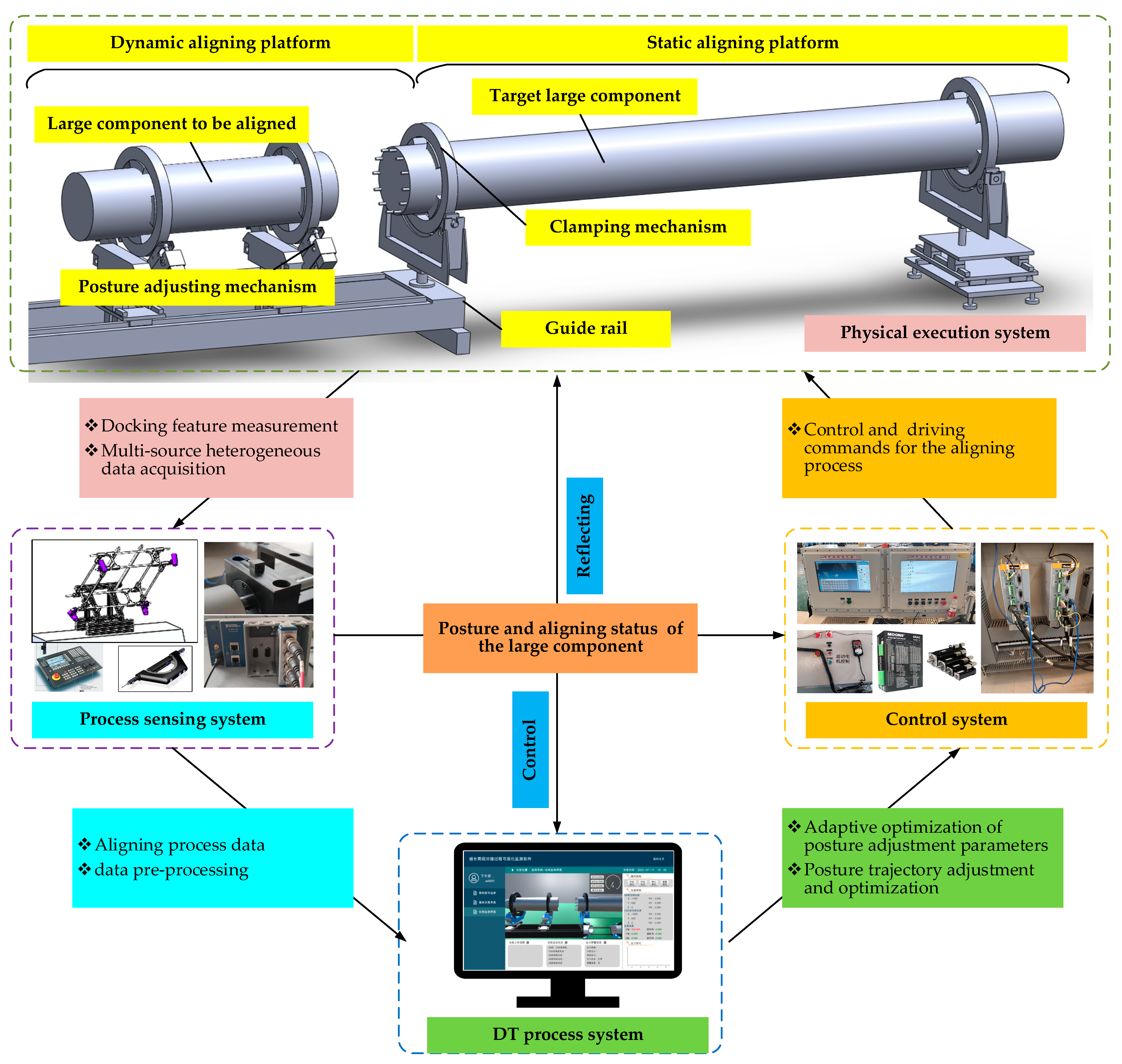
  • The DT process system can achieve the virtual modeling of aligning system entities and plan, adjust, and optimize the aligning process of large cylindrical components. It can also plan the aligning path and perform offline simulation on the generated aligning process. During the process execution, the system can also simulate the aligning process based on real-time process data (e.g., three-dimensional (3D) coordinate data of key measurement points monitored on the large component, aligning force perceived at the aligning surface of the large component) driven by geometric model simulation. In addition, the system also has the functions of the offline simulation and online prediction of aligning errors. Furthermore, based on the prediction of aligning errors, the system can adjust or optimize the posture adjustment parameters of large cylindrical components to generate the adaptive aligning trajectories.
  • The control system mainly generates a motion control code based on the aligning path planned by the DT process system to drive the physical execution system to complete the aligning task of large components. At the same time, according to the adaptive control algorithm designed in the control system, low-level adaptive control of the aligning process can be carried out based on the process execution state, such as adjusting the motor speed and axial feed.
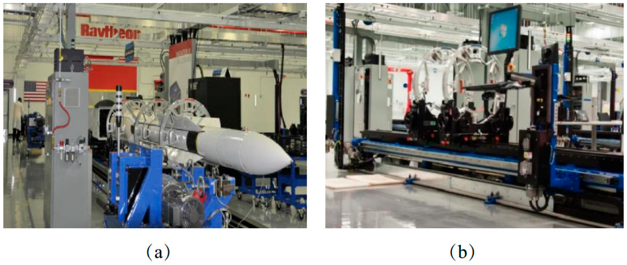
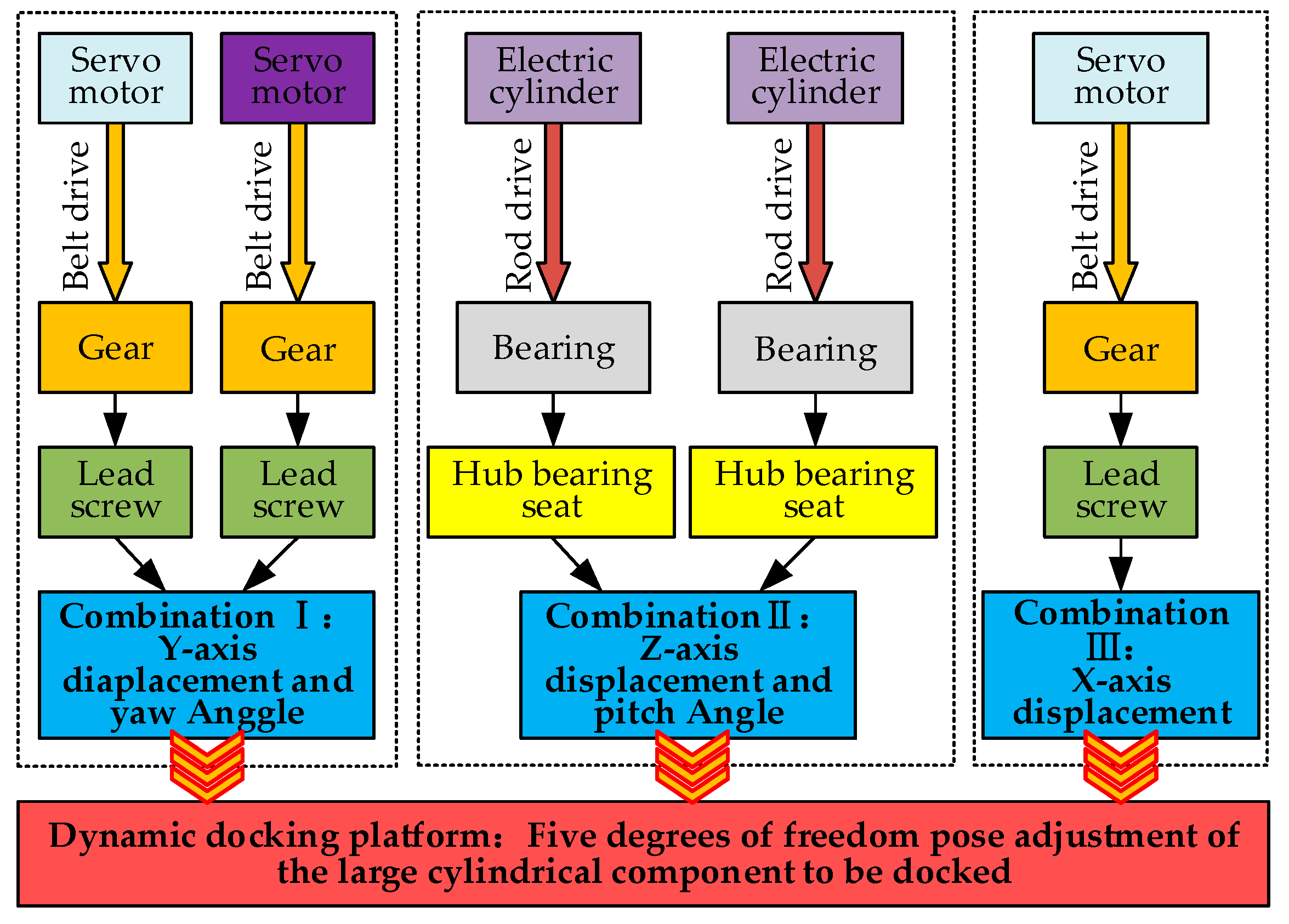
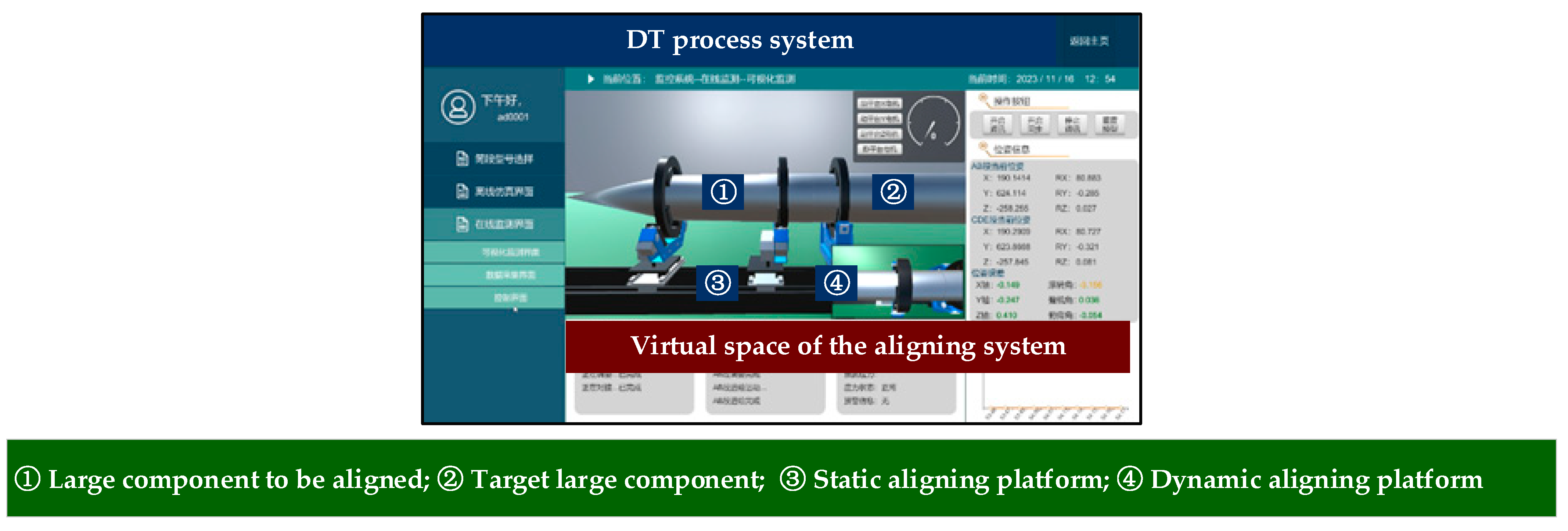
  • The physical execution system refers to the mechanical execution part of the aligning system, which is mainly composed of one static and one dynamic platform system, as shown in Figure 2. The static one is mainly used for installing and positioning the target large cylindrical component, and the dynamic one is mainly used for installing, adjusting, and aligning the large component to be assembled.
  • The process sensing system is mainly responsible for collecting process data during the execution of the aligning process, including the displacement, force, 3D coordinates of key measurement points, etc., so as to realize the adjustment and optimization of the aligning process and thus ensure the aligning quality and efficiency of the large cylindrical component.
In total, through the coordination among the four subsystems mentioned above, the planning and execution control of the aligning process of large components can be realized, and the entire aligning process can be visualized and adjusted or optimized, effectively ensuring the aligning quality and efficiency of large components.

2.2. Aligning Process of Large Cylindrical Components

As shown in Figure 3, the aligning process of the large cylindrical component involves seven sub-processes, i.e., initialization work, installation and clamping of large components, global coordinate system calibration, off-line simulation, rough aligning, finish aligning, and aligning quality evaluation. Each subsystem of the aligning system performs its function in each step of the aligning process and collaboratively realizes the adaptive aligning of large components. Figure 3 illustrates the operational logic of each subsystem in the process and their interrelationships with each other.
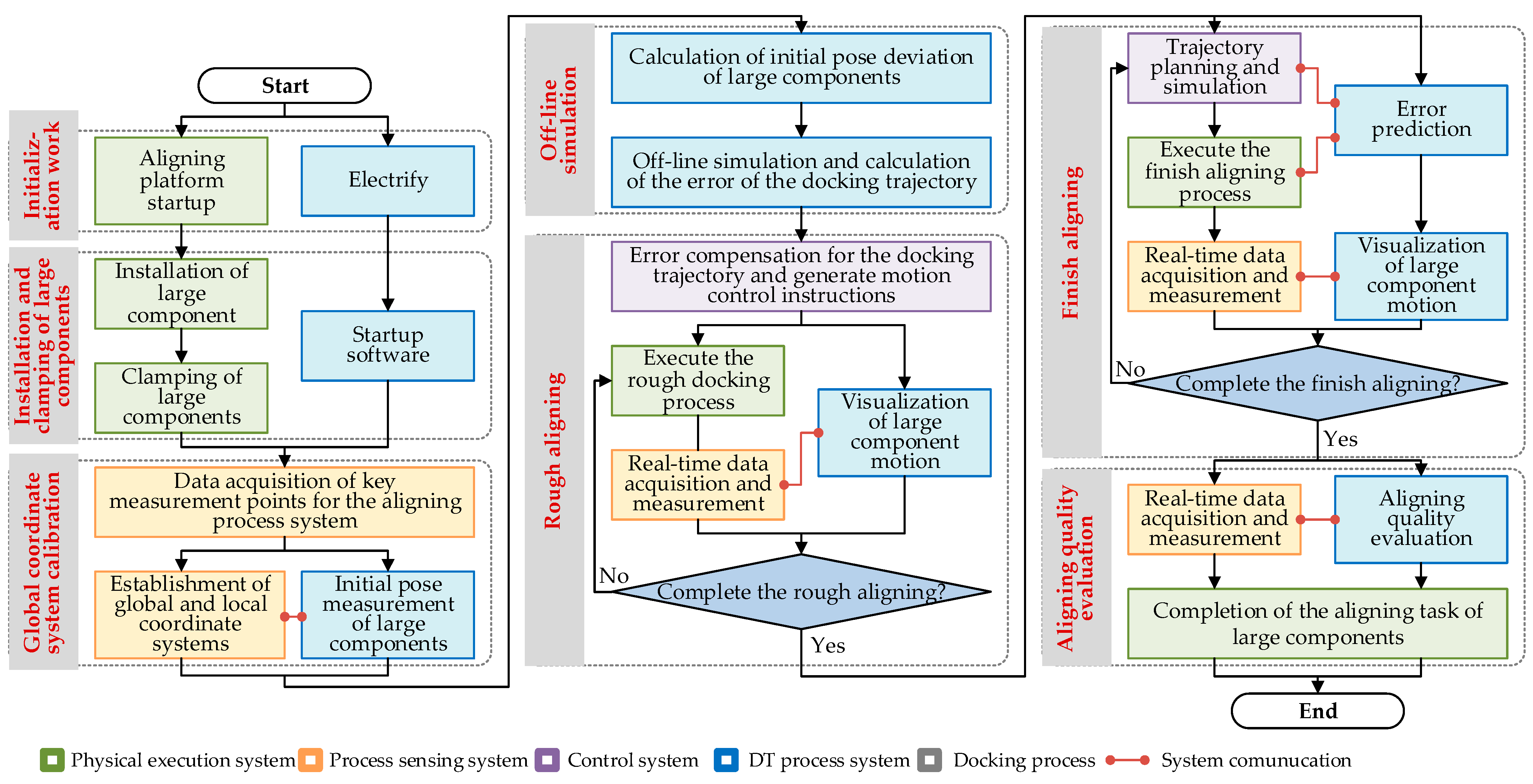
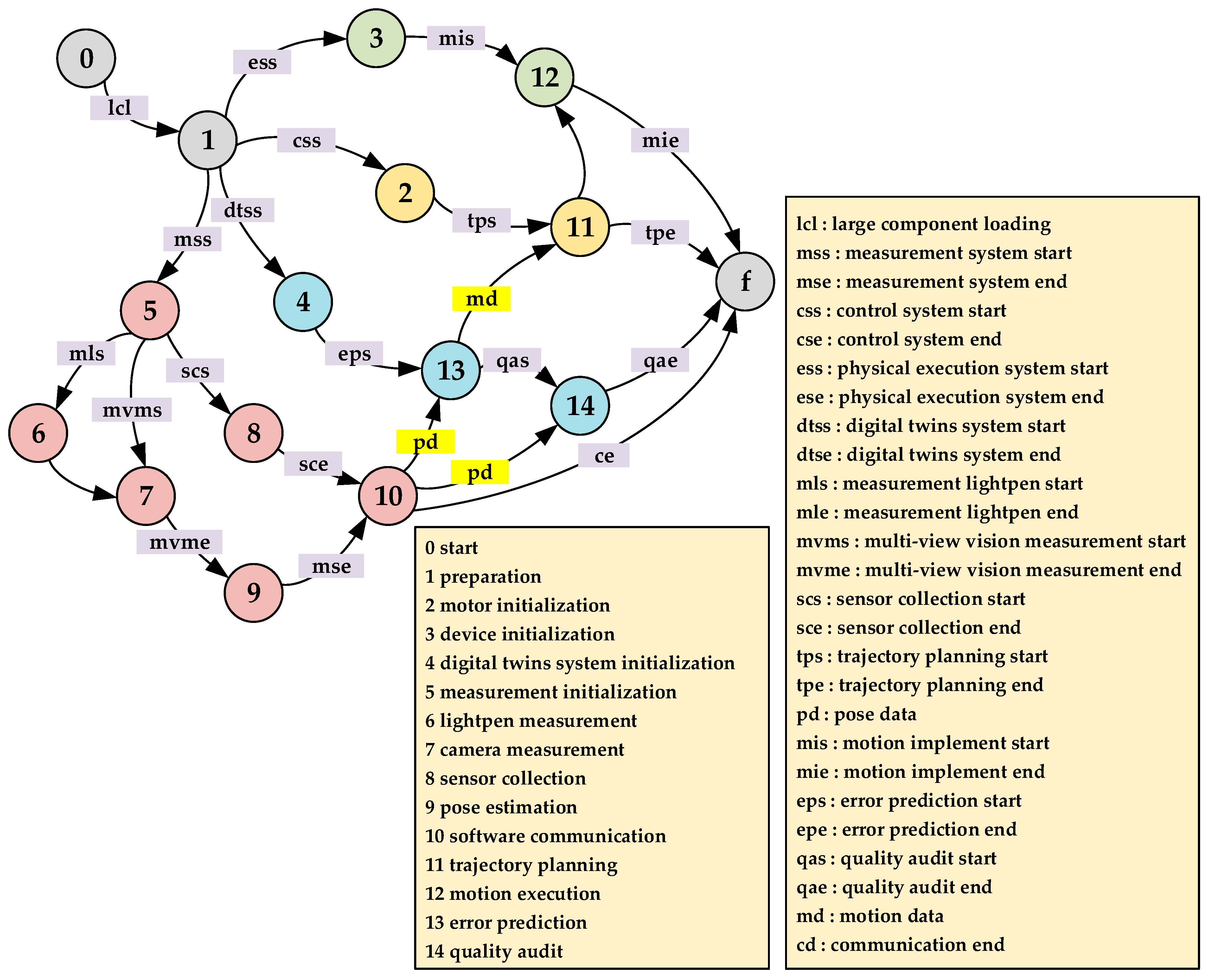
  • Initialization work: the aligning system is turned on and initialized, and the large components are ready to be initially installed and positioned.
  • Installation and clamping of large components: the large components (i.e., the target component and the components to be docked) are respectively placed on the static and dynamic aligning platform and clamped. Meanwhile, the DT process system is opened, and thus, the initial work is completed.
  • Global coordinate system calibration: the vision measurement system is used to measure the 3D coordinates of the key measurement points on the large component and the aligning tool system to construct the local coordinate system of each component (such as the local coordinate system of two large components) and then to construct the global coordinate system of the aligning system, providing a unified coordinate reference for the aligning of large components.
  • Off-line simulation: in the DT process system, the aligning process is simulated based on the measured data, and thus, the error of the aligning trajectory is calculated, which is used to correct the aligning trajectory of the large component to be docked.
  • Rough aligning: based on the off-line simulated and corrected aligning trajectory, the aligning motion control program is generated to perform the rough aligning process. During the rough aligning process execution, the process sensing system collects process information in real time and transmits it to the DT process system for sensing and monitoring the aligning status and quality of large components.
  • Finish aligning: the difference between finish aligning process and rough aligning process lies in the axial feed rate of large components. In the finish aligning stage, the axial feed rate of large components is slower, which effectively protects them from collision and damage. Repeat the above process steps to complete the aligning task of large components.
  • Aligning quality evaluation: after the aligning of large components is completed, the key process data are collected to evaluate the aligning quality, such as whether the axis of the large components is collinear and whether aligning stress is generated. When the aligning quality is satisfied, the aligning process is finished.

2.3. Overall Design of the DT Aligning System

The overall design framework of the DT aligning system is constructed based on the DT modeling method referred in Ref. [21], which integrates physical space, virtual space, and twin data through correlation and fusion, enabling information exchange and virtual-to-physical mapping during the aligning process of the large component. When the performance requirements of the target product are met, the adaptive and optimal operating state of the aligning system is achieved through collaborative control and iterative optimization, as shown in Figure 4.
Physical space: it is the hardware part of the DT aligning system, which is mainly composed of the physical execution system, process sensing system, and the control system. Herein, the dynamic and static platforms, motion control systems, and programmable logic controllers make decisions for aligning tasks and obtain various process data through transmission protocols or multiple sensors to perceive and monitor the aligning status information of large cylindrical components in real time and upload the collected data to virtual space through the network module.
Virtual space: it is the software part of the DT aligning system, which contains the design and modeling modular, and the intelligent decision-making module. The design modeling module maps the properties of physical space devices to virtual space through geometric modeling, physical modeling, data modeling, and functional modeling to construct a twin model of the aligning system. The intelligent decision-making module realizes the consistency between the aligning system in the virtual space and the physical space. The twin model can be continuously improved and optimized through the intelligent decision-making analysis of the algorithm library, and the pre-designed aligning process scheme can be inputted into the intelligent decision-making modular, the aligning program of large cylindrical components can be called, and the interference collision simulation of the aligning trajectory can be carried out to ensure the feasibility of the aligning process scheme. In addition, during the aligning process execution, aligning system calibration, multi-source data processing and fusion, and feedback control can be used to adjust or optimize the aligning process, in order to achieve the closed-loop adaptive aligning of large cylindrical components.
Twin data: there are a large amount of multi-source real-time data in the aligning system. Twin data, as the foundation of the DT aligning system, supports the operation of physical and virtual spaces and is also used for system modeling, feature extraction, and the optimization of decision-making. Data collection, transmission, and storage technologies are crucial for the accuracy and real-time perception of the aligning system information and can achieve the real-time performance monitoring of static and dynamic platforms and the aligning status of large components during the aligning process.
Thus, physical space, virtual space, and twin data combine to form the adaptive aligning system of large cylindrical components, allowing for the high-quality and efficient aligning assembly of large components.

3. Digital Twin Multi-Dimensional Modeling for the DT Aligning System

Through the DT technology, a virtual model of the physical entity of the aligning system can be quickly created, simulated, and analyzed in the virtual space, enabling judgment of the current state, diagnosis of past problems, and prediction of future trends, enhancing analysis and prediction capabilities, providing support for process decision-making for the aligning system, achieving intelligence and efficiency in the aligning process, and improving the quality and efficiency of aligning for large components. Thus, in order to achieve the above objectives, this paper conducts the digital twin modeling of large component aligning systems from four aspects: geometric modeling, physical modeling, data modeling, and functional modeling.

3.1. Geometric Modeling for the DT Aligning System

The geometric model is the main manifestation of studying the aligning process of large components. By establishing a 3D visualized DT model, it describes the geometric properties and motion structure of physical objects, ensuring that the DT model is highly consistent with the physical system in terms of size, material properties, shape, etc., while also reflecting the real assembly relationship and structural subordination relationship of physical objects. Therefore, based on the physical entity of the large component aligning system, a 3D visual virtual model is established to complete the geometric modeling. Specifically, the key transmission parts of the mechanism of the aligning system are retained, and the lightweight CAD modeling of the parts is carried out. Based on the topology model, the assembly structure tree is built to describe the motion structure and transmission relationship of the aligning system. Setting the material and color of the model provides a 3D visual operating environment for the simulation and monitoring of physical objects for the aligning system, as shown in Figure 5.
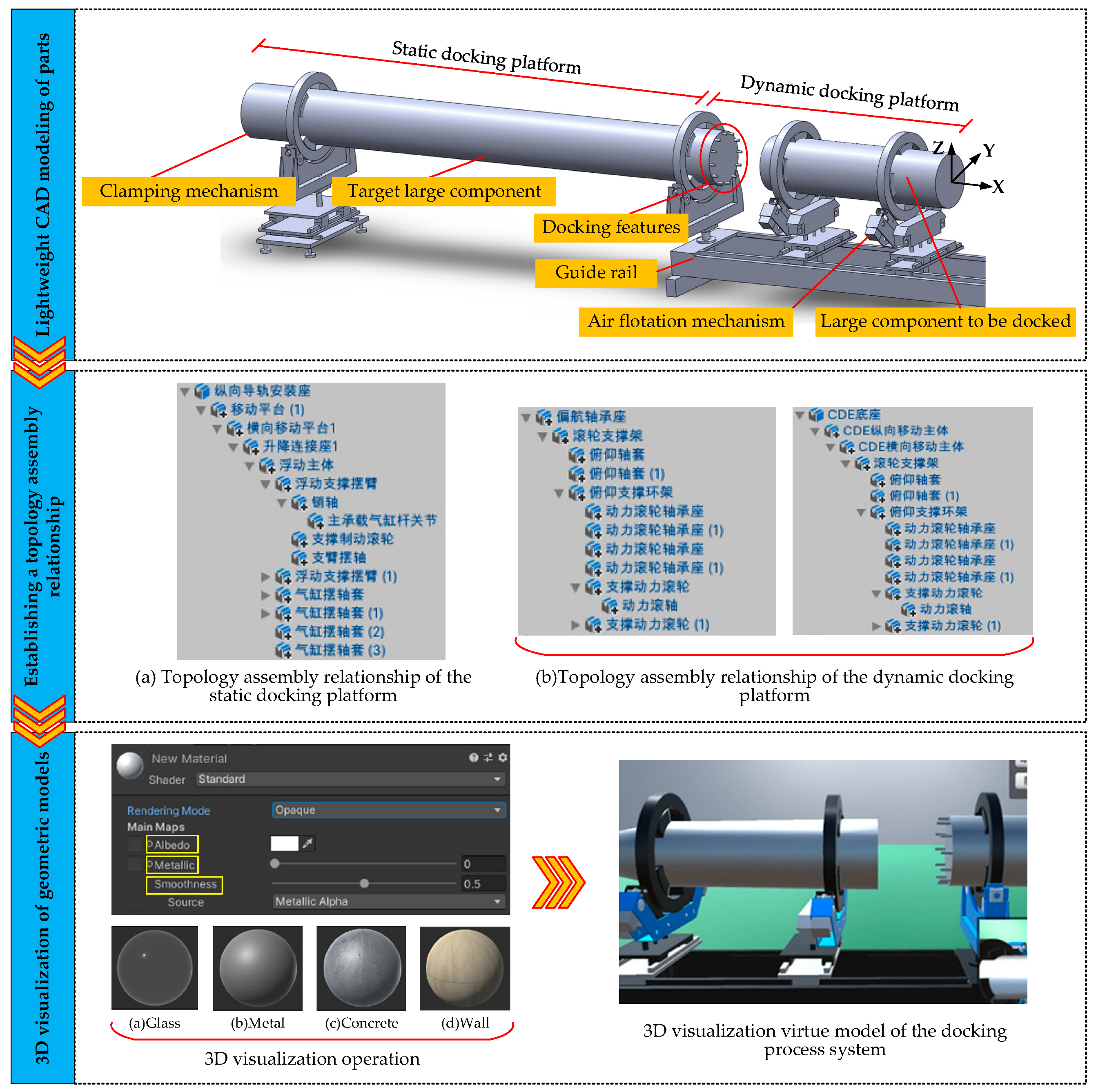
  • Lightweight CAD modeling of parts, in the various modules of the aligning system, there are a large number of small volume components and features (e.g., threads, rounded corners, and grooves) to be designs, which can lead to a sharp increase in the number of modeling grids. On the premise of retaining the key transmission relationships and dimensions of the aligning system, the non-essential components and features are simplified or ignored in accordance with the principle of the model being lightweight. For the posture-adjustment mechanism and guide rail mechanism, the synchronous belt, screw thread, pulley and other components are deleted and merged, and the chamfer features on the guide rail and other components are removed. For the air flotation mechanism, remove components, such as shaft sleeves, bolts, nuts, etc.
  • Establishing a topology assembly relationship: from the kinematic perspective, the physical execution subsystem for the aligning system is a typical multi-body system; therefore, constructing a topological structure chain of the physical execution system can clearly express the relative assembly and transmission relationships between various components of the assembly. At the same time, to ensure that each component model corresponds clearly to the topology nodes, a tree structure is used to store and manage the topology chain during modeling. Importing CAD models as assemblies, the hierarchical nodes of each model are determined by the machine topology, and the 3D solid model is attached to the corresponding topology nodes.
  • 3D visualization of geometric models: according to the physical entity of the aligning system, the model color, material, and other geometric properties are customized. Color, map, and assign material balls to physical entities to change their material properties. At the same time, build a virtual environment scene, perform operations, such as graphics rendering, and restore the physical entity of the interconnecting system.

3.2. Physical Modeling for the DT Aligning System

Physical modeling necessitates that the virtual aligning system model reflects the physical properties of the physical entity system, such as the actual process, process parameters, forces, and so on, and perform dynamic mathematical approximation simulation and characterization at the macro and micro scales. For the aligning system, the physical properties closely related to the aligning process are first selected, i.e., the physical modeling is carried out around the pose adjustment of large components and the feed process of the aligning platform. Note that the aligning process mainly involves the displacement adjustment of the dynamic aligning platform and the pose angle adjustment of large components in the rough aligning process stage; on the other hand, the assembly of the aligning features and the pose fine-adjustment of large components are mainly involved in the finish aligning process stage. In total, the physical properties for the aligning system mainly include the pose information of large components in the whole process and the assembly stress/torque in the finish aligning process stage. Therefore, from the perspectives of kinematics and dynamics, mathematical characterization of the aligning process of the physical execution system is carried out to achieve physical modeling of the aligning system.
The working mechanism of the aligning process platform, as shown in Figure 6, consists of a fixed base, attitude adjustment mechanisms in various directions, and connectors. Note that the motion transmission is from the servo motor to the end of the dynamic aligning platform. The lead screw is divided into three groups according to the combination of the pose-adjustment mechanism and moves along their respective axes to achieve displacement and pose angle changes in that direction, jointly driving the translation and rotation of the dynamic aligning platform and realizing the adjustment of the five degrees of freedom pose of the large component to be docked.
In addition, in the finish aligning stage, the aligning reference of the aligning features is inconsistent under the influence of the aligning error, the aligning stress is generated (e.g., the axis of the pin and the hole of the large cylindrical component are not collinear), which affects the quality of large component aligning. Therefore, it is necessary to analyze the stress conditions of aligning features (i.e., pins and holes) under different poses of large components, establish the relationship between the aligning stress and pose change, and obtain the physical simulation model of contact stress, so as to provide engineering constraint support for the adjustment and optimization of the aligning pose of large components.

3.3. Functional Modeling for the DT Aligning System

Based on the analysis of the full aligning process of large cylindrical components, the basic process units of the aligning process include visual measurement, large component posture adjustment, aligning trajectory planning, aligning process execution, and aligning process monitoring. Based on IEC61499 function block (FB) technology [22,23,24,25], these process units can be designed and packaged into corresponding FBs for adaptive planning and execution control of the aligning process. Thus, pose measurement FB (PM-FB), pose estimation FB (PE-FB), pose adjustment trajectory planning FB (PA-FB), aligning process execution FB (DP-FB), and process monitoring FB (PN-FB) are designed in this research.
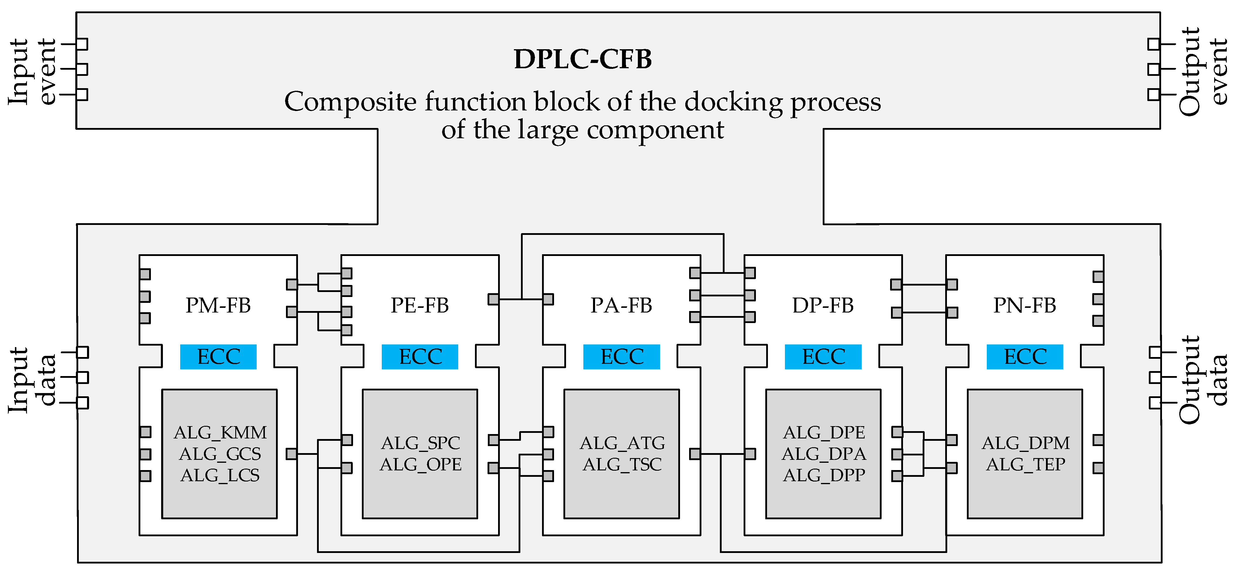
  • PM-FB is used to measure key measurement points of the aligning system, establish coordinate systems for aligning platforms and large components, e.g., the global coordinate system, the workpiece coordinate system for large components, which provides a unified coordinate reference for the aligning process.
  • PE-FB is to evaluate the optimal pose of large components and generate the optimal pose adjustment parameters in terms of considering the engineering constraint conditions of the as-built state of large components.
  • PA-FB is utilized to generate and simulate the pose adjustment trajectory of the large component and transmit the verified adjustment trajectory to DP-FB to enable the control system to generate motion commands to drive the physical execution system to complete the aligning task of large components.
  • PN-FB is mainly used to monitor and control the aligning process of large components, including the real-time monitoring of the pose change and aligning stress, and to predict and compensate for the aligning trajectory error based on the measured pose data, to ensure the quality of large component aligning.
Note that PM-FB, PE-FB, and PA-FB are mainly used to plan the aligning process of the large component; on the other hand, DP-FB and PN-FB are mainly designed for aligning process execution and control, and these FBs are basic function blocks, which are high-level process templates that encapsulate process knowledge and algorithms, and they can be combined into composite functional blocks (CFBs) under a service-oriented event-driven mechanism (as shown in Figure 7); thus, a CFB for the aligning process of the large component is designed, i.e., DPLC-CFB, as shown in Figure 8, which can achieve adaptive aligning process planning and execution control of the large component.

3.4. Data Modeling for the DT Aligning System
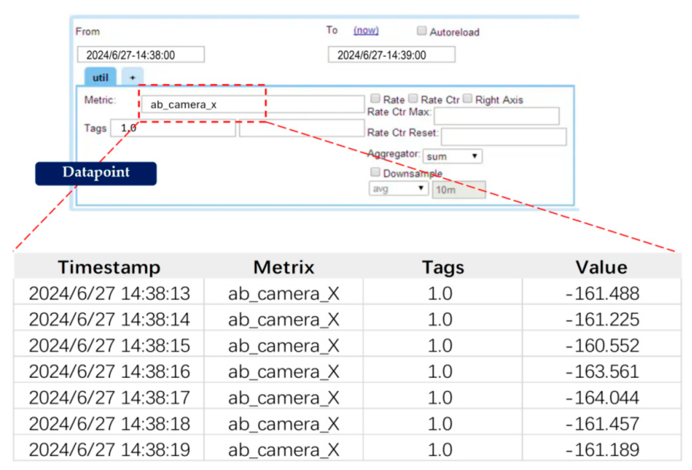
Twin data are an important way to connect physical space and virtual space and are the basis for the mutual mapping between virtual space and physical space. The data obtained during the aligning process will directly affect the process decision output of the DT aligning system, thereby affecting the aligning quality and accuracy of the large component. Therefore, the real-time, accuracy, synchronization, and stability of multi-source data during the aligning process are essential. The main purpose of establishing a twin data model is to achieve the fusion of multi-source data and aligning elements in the aligning process. Regarding the multi-source data obtained based on different acquisition methods during the large component aligning, it can be divided into structured data, parametric data, and monitoring data. The following will introduce from three aspects: data acquisition, data integration, and data storage and management.
  • Data acquisition
As previously mentioned, the physical execution system is mainly composed of mechanical, electrical, control, and others, and its running state and running parameters contain important data information. Thus, this study designed and implemented visual measurement data reading based on the TCP protocol, data reading of the Beckhoff controller based on the ADS protocol, and signal acquisition of the sensor based on the serial port to collect spatial pose data, motor output, and aligning stress during the aligning process, as shown in Table 1.
2.
Data integration
The data collected during the interconnection process are managed in various data formats and methods to facilitate storage, query, and modification. Structured parameter data existing in the aligning system, such as geometric model data (geometric dimensions, assembly relationships, assembly positions, etc., used for virtual model visualization), physical model data (input data required for aligning error prediction mechanism models, relevant data of aligning platform raw errors), user management information, etc., have fixed formats and storage rules, and because they are fixed parameters of the aligning system, they will not be written or modified in batches, which are expressed and managed in a structured manner using tables, as shown in Figure 9.
For the configuration parameter data used in the aligning system, such as the interfaces for transmitting data between subsystems (e.g., communication IP, communication ports), and the parameters required for functional models (e.g., aligning error mechanism model input data, aligning platform raw errors, control algorithm weight coefficients, etc.), it is necessary to be easy to parse, read, write, and modify. Therefore, the XML (eXtensible Markup Language) data format is used for this data modeling, and a unified data format is constructed, achieving the integration and expression of heterogeneous system information. In addition, the relevant algorithm configuration parameter information during the aligning process is stored in an XML format file to achieve the rapid parsing, reading, and modification of key parameter data. For instance, Figure 10 shows some of the system parameter values required for the aligning error prediction and adaptive control algorithm, including assembly constraint information and force-position constraint information for the aligning system. This information is used as the configuration parameter inputs in the algorithm, outputting aligning error, and adaptive control adjustment parameter results for the aligning system of large cylindrical components.
For real-time monitoring data of the aligning system, it refers to all dynamic process data that reflect the operating status, real-time performance, environmental parameters, sudden disturbances, etc. This type of data has the characteristics of large data volume and strong temporal correlation. Therefore, an unstructured data format is used for storage, and the data are defined and managed through timestamps and variable labels (Metrix) in a time-series database for quick writing and querying. For example, Figure 11 shows the displacement of the large cylindrical component in the X direction at different times, i.e., the X-direction displacement values of the same Metrix at different timestamps recorded in a time database, where ab_camera_X represents the displacement of the large component in the X direction measured by the vision measurement system.
3.
Data storage and management
In response to the significant differences in data size, data structure, and data usage among the various types of data analyzed above, appropriate data-storage modes should be selected accordingly. Two types of databases are selected, i.e., SQL Server and OpenTSDB, for deployment and management, and they store XML files to meet the storage requirements of different types of data information. On the basis of successfully obtaining heterogeneous data from multiple sources, data classification, format conversion, and other operations are carried out to provide a data foundation for subsequent research data analysis and application, as shown in Table 2.
In short, based on the constructed data model, the data features of the aligning system are extracted, the mapping between the physical space operating state of the aligning system and the twin data layer is realized, the multi-sensor data and system data of different structures in the aligning process of large components are fused, and the data quality of the aligning process is improved. In summary, by modeling the digital twin of the aligning system in multiple dimensions, the mapping between physical space and virtual space has been achieved, providing system support and an adaptive control decision for the adaptive aligning of large components.

4. Adaptive Control of the Aligning Process for Large Cylindrical Components

The aligning process of large components needs to take into account the positioning accuracy and aligning quality, so it is necessary to combine the measured information and prediction information to carry out the force/position cooperative adaptive control of the aligning system. First, based on the multi-source state information obtained during the aligning process, identify the current assembly status of large components. Then, a mapping model between the aligning state and aligning stress is constructed, based on which the aligning stress of large components under different aligning states can be obtained. Furthermore, by comparing it with the expected position of large components, model reference adaptive control information for large components driven by actual measurement information is obtained. Afterwards, the control information is calculated as the displacement information of the dynamic aligning platform system in the aligning system, and the positioning adjustment of each motion axis in the dynamic platform system is allocated to achieve coordinated control.
  • Aligning status recognition: as shown in Figure 5, the aligning features have multiple holes and pins. To achieve the aligning assembly of large components with multiple pins and holes, it is necessary to first consider the assembly interference problem caused by manufacturing, positioning, and other errors between pins and holes. The geometric analysis of various aligning states is required to obtain the geometric errors of large components in different coordinate directions under different aligning states. Based on the set assembly accuracy constraints in each coordinate direction, the current aligning assembly state of large components can be accurately identified, unassembled, aligning the assembly in progress, aligning the assembly completed, etc. For the aligning assembly in progress, the aligning assembly state is divided and identified based on the translation displacement error or rotation angle error of the coordinate axis, and the discrete aligning assembly states of large components are obtained, such as aligning states with poor translation error along the X-axis, poor rotation angle around the Y-axis together with poor translation error along the Z-axis, etc.
  • Mapping relationship between aligning stress and pose of large component: due to the rather complex force-bearing conditions of the multi-pin-hole assembly, based on the classified types of discrete aligning assembly states, finite element simulations of the aligning stress in various assembly states are necessary. To analyze the displacement, stress, strain, etc., in all assembly states, each unit simulation result needs to be combined to obtain the overall assembly mechanical information. Since the magnitude of the error directly influences the force degree on the contact between the pin and the hole, the independent variable of each simulation is set as a set of discrete pose deviations, and the relationship between the pose deviations and the aligning stress is obtained through parametric scanning. Therefore, based on the discrete pose states of large components, the aligning stress simulations are conducted respectively, and the data are processed by fitting to obtain the mapping relationship between the aligning stress and the pose deviation for the large component.
  • Adaptive control aligning strategy based on geometric and physical aligning state information: the aligning state of large components needs to be characterized simultaneously based on the pose error of geometric quantities and the assembly stress of physical quantities. Thus, in the control strategy, both geometric and physical assembly information, i.e., the basic positioning error constraint and the aligning stress constraint for the large component, need to be considered. A comprehensive evaluation function for the quality of large component aligning is constructed, thereby obtaining the optimal pose-adjustment parameters. The basic positioning error constraint ( e t ( x , y , z , α , β , γ )) is the difference between the current positioning accuracy and the target positioning accuracy of the large component in the current adjustment cycle t. The assembly stress constraint ( F t ( x , y , z , α , β , γ )) refers to the influence of different pose states of the large component on the variation of the aligning stress. Based on the mapping relationship between the pose and aligning stress, the aligning stress at the end of the next cycle is obtained. Therefore, for each control cycle t, the evaluation function for the optimal aligning quality can integrate the above two types of constraints. Thus, the optimization objective function of the quality of large component aligning is expressed as
    P ( x , y , z , α , β , γ ) = M i n [ ω 1 e t ( x , y , z , α , β , γ ) + ω 2 F t ( x , y , z , α , β , γ ) ] S . T . x p t s 1 ,   y p t s 2 ,   z p t s 3 ,   α p t s 4 ,   β p t s 5 ,   γ p t s 6 ,   ω 1 + ω 2 = 1
    where s 1 , s 2 , , s 6 is the maximum allowable change per degree of freedom in the control period. ω 1 , ω 2 are the weights assigned to the positioning accuracy constraint and the aligning stress constraint, respectively. For Equation (1), the multi-gradient descent method can be used to solve it. The Lagrange multiplier method and KKT condition are introduced to transform the optimization problem with constrained inequalities into an unconstrained nonlinear optimization problem, thereby quickly obtaining the local optimal value. Furthermore, the parameter adaptive mechanism is established to adjust the parameters of the process model adaptively according to the errors of the control object and the process model. In the adaptive control strategy with variable weight, the error value is often used as the tuning variable of the rule weight, so as to realize the online self-tuning rule weight allocation. The difference between the execution result and the reference expectation is made, the processed error is superimposed on the current parameter in a certain proportion, and the weight parameters in the multi-objective optimization equation are adjusted based on feedback to realize the self-adaptation of parameter design.
In summary, based on the above algorithm, through the multi-source heterogeneous data acquisition, state perception, pose-adjustment parameter planning and optimization, force position collaborative control, and trajectory error compensation during the aligning process of large cylindrical components, the autonomous decision and accurate execution of the adaptive aligning of large components are realized.

5. DT Aligning System Development and Validation

Based on the aligning process of large cylindrical components of a spacecraft, DT software, i.e., the DT process system, for aligning large cylindrical components was developed, which communicates with the physical execution system, control system, and process sensing system to achieve real-time state perception and process execution decision-making for the aligning assembly of large cylindrical components. Based on the actual aligning process of large cylindrical components, the functionality of the DT aligning system is validated.

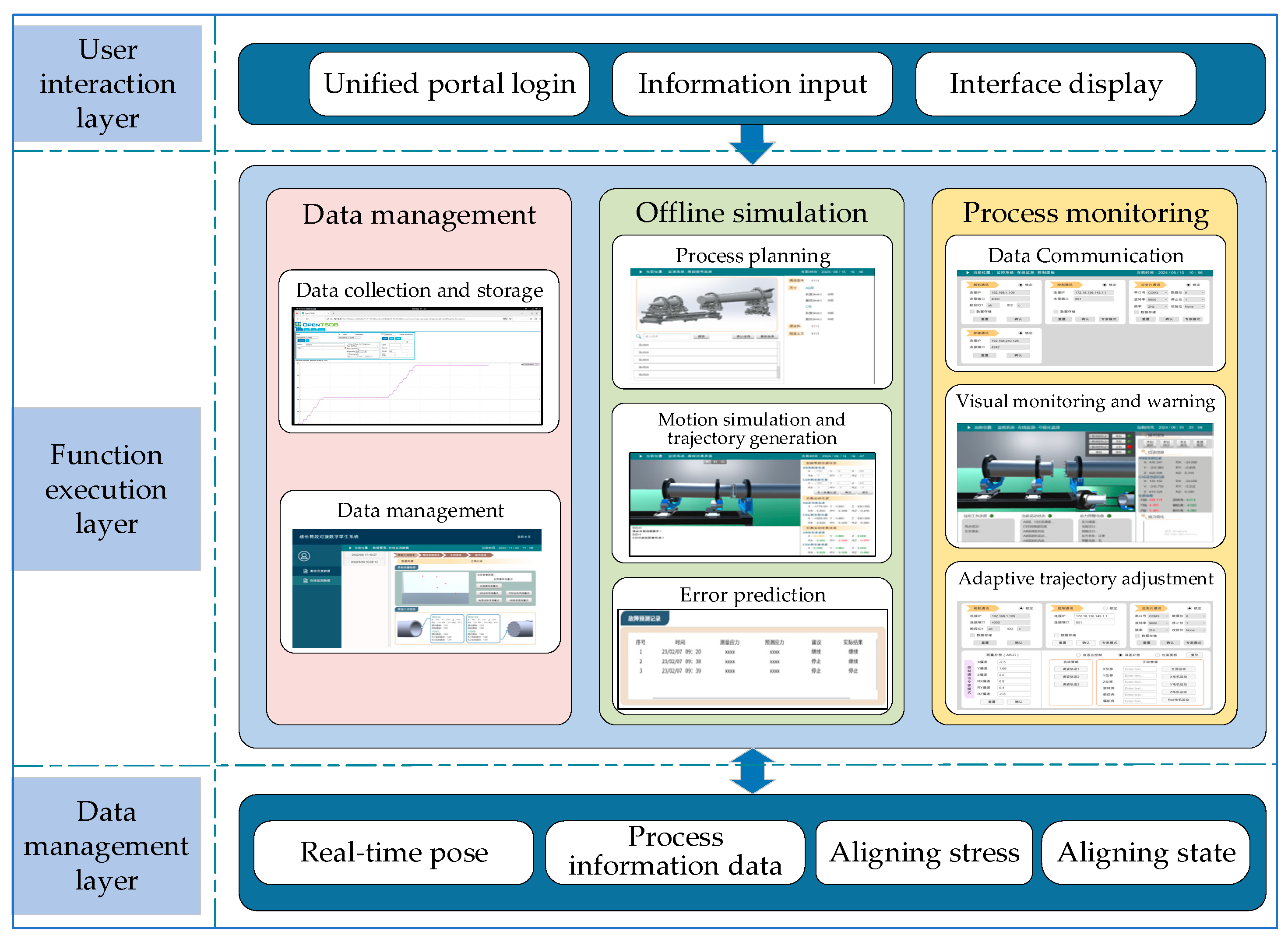
5.1. Software Framework and Development of the DT Process System

For the DT process system, its software architecture consists of a data management layer, a function execution layer, and a user interaction layer, as shown in Figure 12.
  • The data management layer obtains multi-source heterogeneous data in the aligning process and uses different databases to store and manage according to data types and characteristics. In addition, the local area network and HTTP protocol and TCP/IP protocol are applied to achieve data transmission.
  • The functional execution layer provides technical support for the realization of the functional modules and user interface of the DT aligning system. It mainly includes three functional software modules, i.e., data management module, offline simulation module, and process monitoring module. The data management module is mainly used for data collection, storage, and management. The offline simulation module is applied to the aligning process planning and the process performance evaluation, e.g., the aligning error prediction of the large component.
  • The process monitoring module is utilized for the aligning process execution and control. The user interaction interface is implemented based on physical–virtual synchronous mapping, visualizing the simulation and monitoring results of the virtual space digital twin model, transmitting information to the user on the interaction interface, and receiving user interaction and feedback operations.

5.2. Application Validation of the DT Process System

Based on the software framework shown in Figure 12, the Human Machine Interface (HMI) of the developed DT process system is shown in Figure 13, which mainly includes virtual scenes, monitoring function panels, and control panels. The virtual scene reflects the motion state of the twin model of the large component aligning system driven by twin data. The monitoring function panel is responsible for the digital display and control of the aligning status of large components and displays monitoring data in real-time and dynamically. The control panel provides various control functions for the execution control of the large component aligning process.
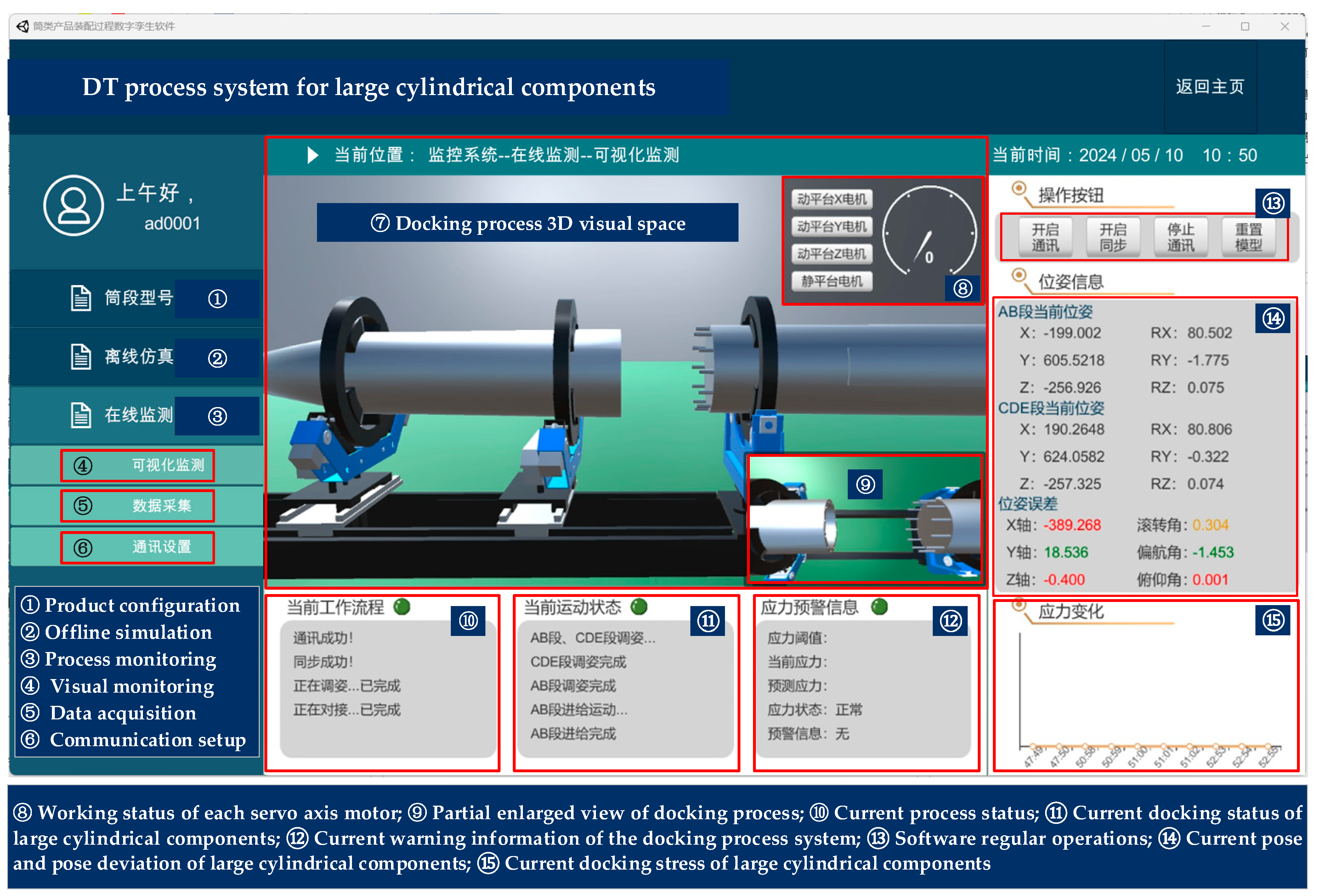
  • Click the action button in the monitoring system to start communication (⑬ in Figure 13); the DT process system establishes communication with the process sensing system, and the sensing system collects multi-source heterogeneous data during the aligning process in real time, including the current pose information of large components and the data of various sensors (e.g., the aligning stress and the servo motor data of the motion shaft).
  • Click the operation button to start synchronization (⑬ in Figure 13); the virtual space of the aligning system synchronizes with its physical space. On the right side of the HMI interface is display information, such as the aligning pose, pose error, and aligning stress of two large components (⑭ and ⑮ in Figure 13).
  • When starting the aligning process, the DT process system synchronously reads the pose and stress state information of large components, displays them on the pose display panel and curve graph, and distinguishes the aligning error of two large components by color. When the error decreases to a controllable range, the error value changes from red to yellow, and when the error meets the aligning accuracy requirements of large components, the error value changes to green. The display of the aligning status also changes with the aligning process of large components. After the aligning process is completed, the process status displays “aligning completed”, and the process status signal indicator light turns green (⑩ in Figure 13).
Finally, as shown in Figure 14, the DT process system was applied to the actual aligning process of large aerospace cylindrical components. The results showed that the DT process system for the aligning process can achieve digital and visual monitoring and control of the aligning process of large components, with low latency and a high degree of visualization and digitization. In addition, the DT process system can achieve the synchronization of virtual and real scenes in the process of large components and multi-perspective monitoring, which has good interactivity and can achieve the adaptive aligning of large components. Finally, in order to verify the effectiveness and practicality of the DT alignment system designed in this paper, a total of 14 aligning experiments were conducted to be compared with the traditional method, and the experimental results are shown in Figure 15.
The experimental results show that the proposed method can greatly enhance the alignment accuracy of large cylindrical components. On the other hand, by analyzing time statistically, the proposed method can considerably reduce the aligning time of large components, enhance aligning efficiency, and significantly boost the level of automation and intelligence for the aligning system.

6. Conclusions

To address the issue of high efficiency and precision in large cylindrical component alignment, a DT aligning system based on digital twin and closed-loop adaptive control technology is proposed in this study, which can improve the quality and efficiency of large component alignment, as well as the level of automation and intelligence. The important contributions of this work are mentioned below.
  • A DT aligning system for large cylindrical components is designed and developed, consisting of a DT process system, a control system, a physical execution system, and a process sensing system, which allows for close-loop adaptive aligning of the large cylindrical component.
  • A multi-dimensional modeling method of the DT aligning system is carried out, including geometric modeling, physical modeling, functional modeling, and data modeling, and is used to realize the association, mapping, and interaction between physical space and virtual space of the aligning system, as well as realize the real-time visual monitoring of physical space aligning.
  • An adaptive aligning control method for the large components based on real-time measured pose data is proposed, allowing for real-time status perception and process execution decision-making while successfully ensuring the quality and efficiency of the large component aligning.
In short, the DT technology was first introduced into the adaptive aligning of large cylindrical components. A DT model of the large component aligning system was constructed from four dimensions: geometric modeling, physical modeling, functional modeling, and data modeling, and the physical entity of the aligning system was comprehensively and realistically depicted and described. On this basis, the DT aligning system for large cylindrical components was designed and developed. And the effectiveness and practicability of the proposed system were experimentally validated, which provides a solution for the real-time monitoring of the large component aligning and can improve the aligning quality and efficiency of large components.

Author Contributions

Conceptualization, W.F., J.Z. (Jieru Zhang) and L.Z.; methodology, W.F., R.X., J.Z. (Jieru Zhang) and L.Z.; validation, W.F., R.X., J.Z. (Jieru Zhang) and L.Z.; data curation, J.Z. (Jian Zhou); software, W.F., R.X., J.Z. (Jieru Zhang) and J.Z. (Jian Zhou); writing—original draft preparation, W.F. and R.X.; writing—review and editing, J.Z. (Jieru Zhang), L.Z. and J.Z. (Jian Zhou); visualization, W.F., R.X., J.Z. (Jieru Zhang), L.Z. and J.Z. (Jian Zhou); supervision, W.F. and L.Z.; funding acquisition, W.F. All authors have read and agreed to the published version of the manuscript.

Funding

This research was funded by the National Natural Science Foundation, China, grant number 52205511.

Institutional Review Board Statement

Not applicable.

Informed Consent Statement

Not applicable.

Data Availability Statement

Data is contained within the article.

Conflicts of Interest

Author Jieru Zhang were employed by the company Beijing Xinfeng Aerospace Equipment Co., Ltd. The remaining authors declare that the research was conducted in the absence of any commercial or financial relationships that could be construed as a potential conflict of interest.

References

  1. Wen, K.; Du, F.Z.; Zhang, T.J.; Xiong, Z.Q. Research on design and experiment for digital flexible aligning system of cabin components. Aeronaut. Manuf. Technol. 2017, 11, 24–31. [Google Scholar]
  2. Dai, W.B.; Hu, R.X.; Yi, W.M. The flexible aligning technology for large spacecraft cabins. Spacecr. Environ. Eng. 2014, 31, 584–588. [Google Scholar]
  3. Jackson, K.; Efthymiou, K.; Borton, J. Digital manufacturing and flexible assembly technologies for reconfigurable aerospace production systems. Procedia CIRP 2016, 52, 274–279. [Google Scholar] [CrossRef]
  4. Luo, Q.; Wang, Q.; Liu, Z.H.; Liu, B.F.; Zhang, Q. Wing-Fuselage Compliant Aligning Assembly and Contact Force Analysis Method. J. Nanjing Univ. Aeronaut. Astronaut. 2022, 54, 439–449. [Google Scholar]
  5. Zhu, X.S.; Chen, X.M.; Xie, Y. Application and development trend of high-precision digital measurement technology in aviation industry. Manuf. Technol. Mach. Tool 2019, 683, 57–63. [Google Scholar]
  6. Qiu, B.G.; Jiang, J.X.; Bi, Y.B. Posture alignment and joining test system for large aircraft fuselages. Acta Aeronaut. Astronaut. Sin. 2011, 32, 908–919. [Google Scholar]
  7. Jiang, J.X.; Bian, C.; Ke, Y.L. A new method for automatic shaft-hole assembly of aircraft components. Assem. Autom. 2017, 3, 64–70. [Google Scholar] [CrossRef]
  8. Bond, J. Mission critical: Precision in the air and on the ground. Mod. Mater. Handl. 2013, 68, 48–50. [Google Scholar]
  9. Jing, X.S.; Zhang, P.F.; Wang, Z.J.; Zhao, G. Digital combined measuring technology assisted quality inspection for aircraft assembly. J. Beijing Univ. Aeronaut. Astronaut. 2015, 41, 1196–1201. [Google Scholar]
  10. Yuan, Z.M.; Han, F.; Li, M.Y. Research on large size shape auxiliary measuring device based on laser tracker. Aviat. Precis. Manuf. Technol. 2014, 50, 9–11. [Google Scholar]
  11. Fan, W.; Zheng, L.Y.; Ji, W.; Xu, X.; Lu, Y.Q.; Wang, L.H. A machining accuracy informed adaptive positioning method for finish machining of assembly interfaces of large-scale aircraft components. Robot. Comput.-Integr. Manuf. 2021, 67, 102021. [Google Scholar] [CrossRef]
  12. Sun, X.; Bao, J.; Li, J.; Zhang, Y.; Liu, S.; Zhou, B. A digital twin-driven approach for the assembly-commissioning of high precision products. Robot. Comput.-Integr. Manuf. 2020, 61, 101839. [Google Scholar] [CrossRef]
  13. Xu, C.; Tang, Z.; Yu, H.; Zeng, P.; Kong, L. Digital twin-driven collaborative scheduling for heterogeneous task and edge-end resource via multi-agent deep reinforcement learning. IEEE J. Sel. Areas Commun. 2023, 10, 41. [Google Scholar] [CrossRef]
  14. Ma, X.; Qi, Q.; Tao, F. An ontology-based data-model coupling approach for digital twin. Robot. Comput. Integr. Manuf. Int. J. Manuf. Prod. Process Dev. 2024, 86, 102649.1–102649.11. [Google Scholar] [CrossRef]
  15. Grieves, M.; Vickers, J. Digital twin: Mitigating unpredictable, undesirable emergent behavior in complex systems. In Transdisciplinary Perspectives on Complex Systems; Kahlen, F.J., Flumerfelt, S., Alves, A., Eds.; Springer: Berlin/Heidelberg, Germany, 2017; pp. 85–113. [Google Scholar]
  16. Tao, F.; Qi, Q. Make more digital twins. Nature 2019, 573, 490–491. [Google Scholar] [CrossRef]
  17. Kritzinger, W.; Karner, M.; Traar, G.; Henjes, J.; Sihn, W. Digital Twin in manufacturing: A categorical literature review and classification. IFAC Pap. Online 2018, 51, 1016–1022. [Google Scholar] [CrossRef]
  18. Qian, W.; Guo, Y.; Zhang, H.; Huang, S.; Zhang, L.; Zhou, H. Digital twin driven production progress prediction for discrete manufacturing workshop. Robot. Comput.-Integr. Manuf. 2023, 80, 102456. [Google Scholar] [CrossRef]
  19. Mashaly, M. Connecting the twins: A review on digital twin technology & its networking requirements. Procedia Comput. Sci. 2021, 184, 299–305. [Google Scholar]
  20. Jiang, H.; Qin, S.; Fu, J.; Zhang, J.; Ding, G. How to model and implement connections between physical and virtual models for digital twin application. J. Manuf. Syst. 2021, 58, 36–51. [Google Scholar] [CrossRef]
  21. Tao, F.; Ma, X.; Qi, Q.; Liu, W.; Zhang, K.; Zhang, C. Theory and key technologies of digital twin connection and interaction. Comput. Integr. Manuf. Syst. 2023, 29, 1–10. [Google Scholar]
  22. Fan, W.; Zheng, L.; Ji, W.; Xu, X.; Zhao, X. Function block-based closed-loop adaptive machining for assembly interfaces of largescale aircraft components. Robot. Comput. -Integr. Manuf. 2020, 66, 101994. [Google Scholar] [CrossRef]
  23. Adamson, G.; Wang, L.; Moore, P. Feature-based function block control framework for manufacturing equipment in cloud environments. Int. J. Prod. Res. 2019, 57, 3954–3974. [Google Scholar] [CrossRef]
  24. Wang, L.; Schmidt, B.; Givehchi, M.; Adamson, G. Robotic assembly planning and control with enhanced adaptability through function blocks. Int. J. Adv. Manuf. Technol. 2015, 77, 705–715. [Google Scholar] [CrossRef]
  25. Wang, L. An overview of function block enabled adaptive process planning for machining. J. Manuf. Syst. 2015, 35, 10–25. [Google Scholar] [CrossRef]
Figure 1. A typical automated aligning platform for large cylindrical components [8]. (a) Aligning system view 1. (b) Aligning system view 2.
Applsci 14 08307 g001
Figure 2. Overall framework of the DT aligning system.
Applsci 14 08307 g002
Figure 3. Aligning process of large cylindrical components.
Applsci 14 08307 g003
Figure 4. Overall design framework of the DT aligning system.
Applsci 14 08307 g004
Figure 5. Geometric modeling for the DT aligning system.
Applsci 14 08307 g005
Figure 6. Working mechanism of the aligning process platform.
Applsci 14 08307 g006
Figure 7. Service-oriented event-driven mechanism for the designed FBs.
Applsci 14 08307 g007
Figure 8. Graphical definition mode of DPLC-CFB.
Applsci 14 08307 g008
Figure 9. Structured data representation.
Applsci 14 08307 g009
Figure 10. Data expression in XML format.
Applsci 14 08307 g010
Figure 11. Data expression in temporal format.
Applsci 14 08307 g011
Figure 12. Software framework of DT process System.
Applsci 14 08307 g012
Figure 13. HMI of the developed DT process system.
Applsci 14 08307 g013
Figure 14. Practical application scenarios of the DT process system.
Applsci 14 08307 g014
Figure 15. Comparison of experimental results between traditional methods and the proposed method. (a) Aligning error in the X−direction of large cylindrical components. (b) Aligning error in the Y−direction of large cylindrical components. (c) Aligning error in the Z−direction of large cylindrical components. (d) Total aligning error of large cylindrical components.
Applsci 14 08307 g015
Table 1. Multi-source heterogeneous data of aligning system.
Data NameData TypeCommunication Interface
Visual measurement dataMeasure the position coordinates of spatial points and solve the spatial pose of large componentsThe measurement software communicates with the device via Bluetooth
Strain gauge sensor dataMonitoring the aligning stress changes at the interface of large componentsRS485 Serial port for communication over MODBUS
Beckhoff controller dataObtain information, such as relative displacement of the driver, motor movement, speed, etc.TwinCAT development platform to read the PLC address, need to know the target amount of PLC address in advance
Table 2. Characteristics of different types of databases for the aligning system.
Data Storage TypeCharacteristicOptional Storage Form
Relational dataStructured, business data storageSQL Server
Time serial dataLarge-scale data storage, efficient queryOpenTSDB
Configuration dataEasy to parse and fast read/writeXML
Disclaimer/Publisher’s Note: The statements, opinions and data contained in all publications are solely those of the individual author(s) and contributor(s) and not of MDPI and/or the editor(s). MDPI and/or the editor(s) disclaim responsibility for any injury to people or property resulting from any ideas, methods, instructions or products referred to in the content.

