Review

Critical Review and Potential Improvement of the New International Airport Pavement Strength Rating System

School of Science, Technology and Engineering, University of the Sunshine Coast, Sippy Downs, QLD 4556, Australia
Appl. Sci. 2024, 14(18), 8491; https://doi.org/10.3390/app14188491
Submission received: 14 August 2024 / Revised: 29 August 2024 / Accepted: 9 September 2024 / Published: 20 September 2024

Abstract

:
Most airports rate and publish the strength of their runway pavement using the international system known as Aircraft Classification Number–Pavement Classification Number (ACN–PCN). The ACN–PCN system has been in place since 1981 and includes many simplifications that were necessary at the time of its development, primarily due to the general absence of computer power to support more sophisticated analysis. However, airport pavement thickness determination has evolved since that time and now includes much more sophisticated analysis methods. To bring the strength rating system into line with contemporary pavement thickness determination methods, a new system has been developed, known as Aircraft Classification Rating–Pavement Classification Rating (ACR–PCR). This critical review found that ACR–PCR provides many improvements over ACN–PCN, including minimizing anomalies between pavement thickness design and subsequent pavement strength rating, the use of more representative aircraft traffic loadings and pavement structures, and the alignment of rigid and flexible subgrade support categories. However, ACR–PCR could be improved with regard to the representative subgrade characteristic values, the retention of an overly simple tire pressure category limit approach for surface protection, the provisions for single-wheeled light aircraft pavements, and the absence of a rational approach to strength rating that is substantially better than a usage-based approach but does not necessarily follow the formalized technical rating protocol. Despite these limitations, the current ACN–PCN system has been in place for over 40 years without significant change, so it is expected that ACR–PCR will be in place for many years as well. Consequently, airports should prepare for its imminent introduction, regardless of the associated limitations.

1. Introduction

Since their first introduction in the early 1900s, aircraft have become larger and heavier. Particularly since WWII, aircraft wheel loads and tire pressures have increased significantly [1,2] and this requires ever-stronger pavements to be provided by airports. In 1958, the USA Federal Aviation Administration (FAA) of the United States of America (USA) implemented a policy to restrict the development of new aircraft that stressed pavements more than a DC8-50 aircraft operating at 159 t. In 2009, the FAA pavement protection policy was withdrawn, effectively allowing more demanding aircraft to be developed without restriction [3]. Consequently, the provision of airport pavements capable of accommodating any more demanding future aircraft became the responsibility of airport owners. The trend of increasing aircraft tire pressures and individual wheel loads has continued since that time and is not expected to abate in the future [4].
To assist airport owners and operators in controlling and managing the impact of different aircraft on their pavements, the International Civil Aviation Organization (ICAO) introduced an internationally recognized system for airport pavement strength rating in 1981 [5]. The current system is known as Aircraft Classification Number–Pavement Classification Number (ACN–PCN). As explained in detail below, each aircraft, at a specific weight and tire pressure, has a mathematically exact ACN value, depending on the type of pavement and level of subgrade support. The ACN is compared to the PCN value assigned to a specific runway pavement, which represents the bearing strength of the pavement. The PCN is more subjective and can be assigned using a technical or rational basis or via performance-based experience or usage. When the ACN is equal to or below the PCN, the aircraft can operate in an unrestricted manner. However, when the ACN exceeds the PCN, permission must be sought and granted from the airport operator before that aircraft can operate, referred to as a pavement concession or an overload operation.
When ACN–PCN was developed in the 1970s, pavement design processes were based on simple mathematics, such as a standard pavement composition, Boussinesq’s single layer theory of stress distribution within a pavement, the equivalent aircraft concept, where other aircraft are converted to an equivalent number of the critical aircraft, and the CBR method of pavement thickness determination [6]. Consequently, ACN–PCN was also based on the same simple mathematics. Since that time, pavement design methods have developed, with modern aircraft pavement design methods routinely based on layered elastic analysis and more sophisticated methods for combing the effect of different aircraft, known as the cumulative damage factor, which relies on Miner’s law of damage superposition [7]. Some pavement design methods, including rigid pavement design using the software known as FAARFIELD [8], also use finite element methods [9]. Despite this, ACN–PCN has remained largely as it was when it was originally developed, with only minor changes over time [7].
Some countries provide only limited guidance on the calculation of a PCN for any given runway. For example, Australian regulations only require a runway to be strong enough for the aircraft that operate on it [10]. This largely reflects the focus on the safety of many modern airport regulators, the fact that pavement strength is rarely the cause of a safety-related issue, and the general transition from state ownership of airports to a combination of private airport ownership of major airports and local government management of regional airports [11]. In contrast, some countries mandate specific protocols for PCN calculation, which is more appropriate in locations where the same regulator also has a prescribed pavement design and specification system in place and provides a significant portion of the funding for new pavement development and existing pavement rehabilitation. The PCN calculation protocol published by the FAA is a good example [12]. However, the combination of sophisticated modern airport pavement design methods, with the simpler methods embedded in ACN–PCN for pavement strength rating, has resulted in anomalies. The most common example is where a pavement is appropriately designed for a fleet of aircraft, but when the design is complete and the strength rating is assigned, the simpler mathematics associated with ACN–PCN results in a strength rating that does not allow all the aircraft in that fleet to operate in an unrestricted manner. For example, a B777-300ER has an ACN of 121 on a flexible pavement with a subgrade category D. When a pavement is designed using the layered elastic software FAARFIELD [8] but is rated by the software COMFAA [13] according to the FAA method, it is possible that a PCN of 118 is assigned, and an unintended operational restriction is triggered. In theory, that requires a pavement concession for the B777-300ER, even though it was appropriately provided for in the pavement thickness design.
The most concerning example of these potential anomalies occurred in new airport developments in India, where private entities were contracted to construct new airports to cater to certain numbers and types of aircraft, with all pavements designed and constructed according to the requirements of the FAA. When the construction was complete and the pavement strength rating was performed for the airport authority, the anomalies had the potential to cause some runways to need to provide a pavement concession for the most damaging aircraft in the design aircraft fleet [14]. This could have been interpreted to mean that the private contractor had failed to deliver on the project requirements, and this could have resulted in contractual disagreement. In reality, the contractor would have designed and constructed the pavements as required, but differences between pavement design and pavement strength rating potentially resulted in some runways being rated slightly below that required to allow all the aircraft in the design traffic fleet to operate in an unrestricted manner. Tipnis and Patil [14] subsequently recommended that future pavement strength ratings be performed in FAARFIELD, taking advantage of the more sophisticated mathematics already being used for pavement thickness design.
In response to these anomalies between pavement thickness design and pavement strength rating, ICAO developed a new strength rating system that uses more sophisticated mathematics aligned to those used in modern pavement thickness determination software [15]. The new system, known as Aircraft Classification Rating–Pavement Classification Rating, or ACR–PCR [16], operates in a similar manner to ACN–PCN [17]. However, every aircraft has a new ACR value that cannot be uniquely scaled from the equivalent ACN. As a result, each airport must determine and publish a new PCR to replace the current PCN for each of their runways, and this is due to be implemented by November 2024 [18].
The aim of this research was to review the new international airport pavement strength rating system, known as ACR–PCR. Potential improvements to the system are then explored to address any issues or missed opportunities. It is hoped that the identified issues and potential improvements will increase the usefulness of the new system and reduce the burden associated with the transition from the existing system to the new one.

2. Background

2.1. Airport Pavements

Like road and highway pavements, airport pavements are designed to protect the natural or imported subgrade from the traffic loads they are expected to support over their design life. Furthermore, airport pavements are generally either rigid or flexible in nature, although some composite pavements are also used [19]. Traditionally, flexible airport pavements were designed to comprise thick layers of well-compacted and high-quality crushed rock base over uncrushed gravel sub-base, with a thin bituminous surfacing. The pavement thickness was determined using the methods developed by the US Army Corps of Engineers between the 1940s and 1970s [20].
Since that time, many counties have developed significantly different flexible pavement styles, with much thicker asphalt, bound or stabilized sub-base layers, and some use full-depth asphalt structures [21]. In contrast, Australia has largely retained flexible pavement comprised of relatively thin asphalt surfaces, often 60 mm or 120 mm thick, over high-quality crushed rock base and sub-base layers [7].
Furthermore, rigid airport pavements have changed little since their original development. Rigid airport pavements in most parts of the world remain constructed of unreinforced concrete slabs on a cement-bound or crushed rock sub-base layer [22]. The joints are generally spaced to form 4 m to 7.5 m and approximately square slabs and are detailed to provide partial load transfer from one slab to the next, in order to avoid the need to thicken the slab edges [23]. There are also hybrid or composite pavements, usually where old concrete slabs are overlayed with an asphalt concrete surface [19]. However, these pavements are not common.
Regardless of the type of pavement, most airports subscribe to a standard international aircraft pavement strength rating system. Although there are other systems available and historically used, the most common system is ACN–PCN [5]. As stated above, ACN–PCN was developed and implemented by ICAO in the 1980s and is being replaced by the ACR–PCR system in 2024 [17].

2.2. International Civil Aviation Organisation

ICAO is the arm of the United Nations responsible for international civil aviation [24]. This includes aircraft certification, airport operations, aircraft flight operations, and airport infrastructure design and management. Airport pavement design includes airport pavement requirements, which are generally covered by the ICAO Annex 14 [25]. The requirements of Annex 14 are detailed in the Aerodrome Design Manual Part 3–Airport Pavements [16]. This includes the requirements of the current ACN–PCN system [5] as well as the replacement ACR–PCR system [16]. ICAO represents approximately 190 member states [26] that are required to implement the requirements of Annex 14 in their respective countries, except where a local exception is filed. Consequently, most airports, in most parts of the world, are required to transition to the new airport pavement strength rating system in November 2024.

2.3. Pavement Strength Rating Systems

The aim of any pavement strength rating system is to manage the vehicle (or aircraft) loads that are applied to the pavement, so as not to overload and fail the pavement, for both vehicle/aircraft safety, as well as for the provision of cost-effective infrastructure [27]. In the road and highway context, axle load limits are often placed on trucks, with single-axle, dual-axle, and tri-axle vehicles assigned different axle group weight limits. The different limits reflect the ability of multiple axles to spread the total load more effectively, but not as effectively as the same number of broadly spaced single axles [7]. Axle load limits are usually controlled by the road pavement authority and reflect the combination of road pavement design in that State, as well as the licensing of truck vehicles in that State. Localized reductions in the load limits may also apply to local streets, urban areas, and bridges that have a reduced load-carrying capacity [28]. However, the physical limits of road, bridge, and truck design mean that similar axle load limits apply in many parts of the world.
In contrast to road vehicles, aircraft wheel and axle loads vary greatly. A small regional aircraft might have a total weight of 10 tones on four main gear wheels, resulting in approximately 2.5 tones per wheel being applied to the pavement. In contrast, large commercial aircraft support up to 575 tones on 20 main wheels (A380) and some aircraft have individual wheel loads of up to 34 tonnes (A350-900).
The other element of the airport pavement strength rating system is the surface protection element. This was introduced with ACN–PCN because aircraft have high tire pressures compared to road vehicles, with 1650 kPa now common for large commercial aircraft (A350-900) and over 2000 kPa common for small military jet fighter aircraft (F-15C). Because of the importance of tire pressure to pavement surface damage, in combination with the low tolerance of airport pavement surface distress [29], controlling the impact of the aircraft loading on the pavement surface is important.

3. Review of the ACN–PCN and ACR–PCR Systems

3.1. Existing Strength Rating System

The current ACN–PCN system was developed in the late 1970s and implemented in 1981. Under the current system, aircraft loads are expressed by an ACN, which allows no discretion. The ACN is defined as twice the wheel load (in tones), which, on a single wheel, inflated to 1.25 MPa, causes vertical pavement deflection (calculated at the top of the subgrade) equal to that caused by the actual multi-wheel aircraft gear at its actual gear load and its actual tire pressure [25]. The more wheels in the wheel load group, which is usually a single main gear leg or strut on an aircraft, the more load the wheel group can carry before causing a particular amount of deflection at the subgrade, in a similar manner to multiple axles gear of large trucks being associated with a higher axle group load limit.
Importantly, aircraft wheels interact and cause different amounts of relative damage differently for flexible and rigid pavement structures. This reflects the different ways in which the two pavement types resist and accommodate aircraft loads, with flexible pavements spreading the load and dissipating the resulting stress with increasing depth, while rigid pavements bend to resist the load internally, with the highest stress usually occurring at the joints [30]. Because of the different relative effects of different aircraft on these two pavement types, each aircraft has a different ACN for a rigid pavement than it does for a flexible pavement [7].
The interaction between the multiple wheels on an aircraft landing gear also changes with pavement depth. This means that two aircraft with different landing gear configurations but the same ACN for a particular subgrade category will cause relatively different damage to pavements with different thicknesses, where the wheels interact less (thinner pavement) or more (thicker pavement). Furthermore, pavement thickness is significantly affected by subgrade bearing capacity, commonly expressed as the California Bearing Ratio (CBR). Consequently, the application of ACN–PCN therefore changes with subgrade bearing capacity, as a proxy for the pavement thickness, to reflect the degree of wheel interaction at the critical top of subgrade depth below the pavement surface.
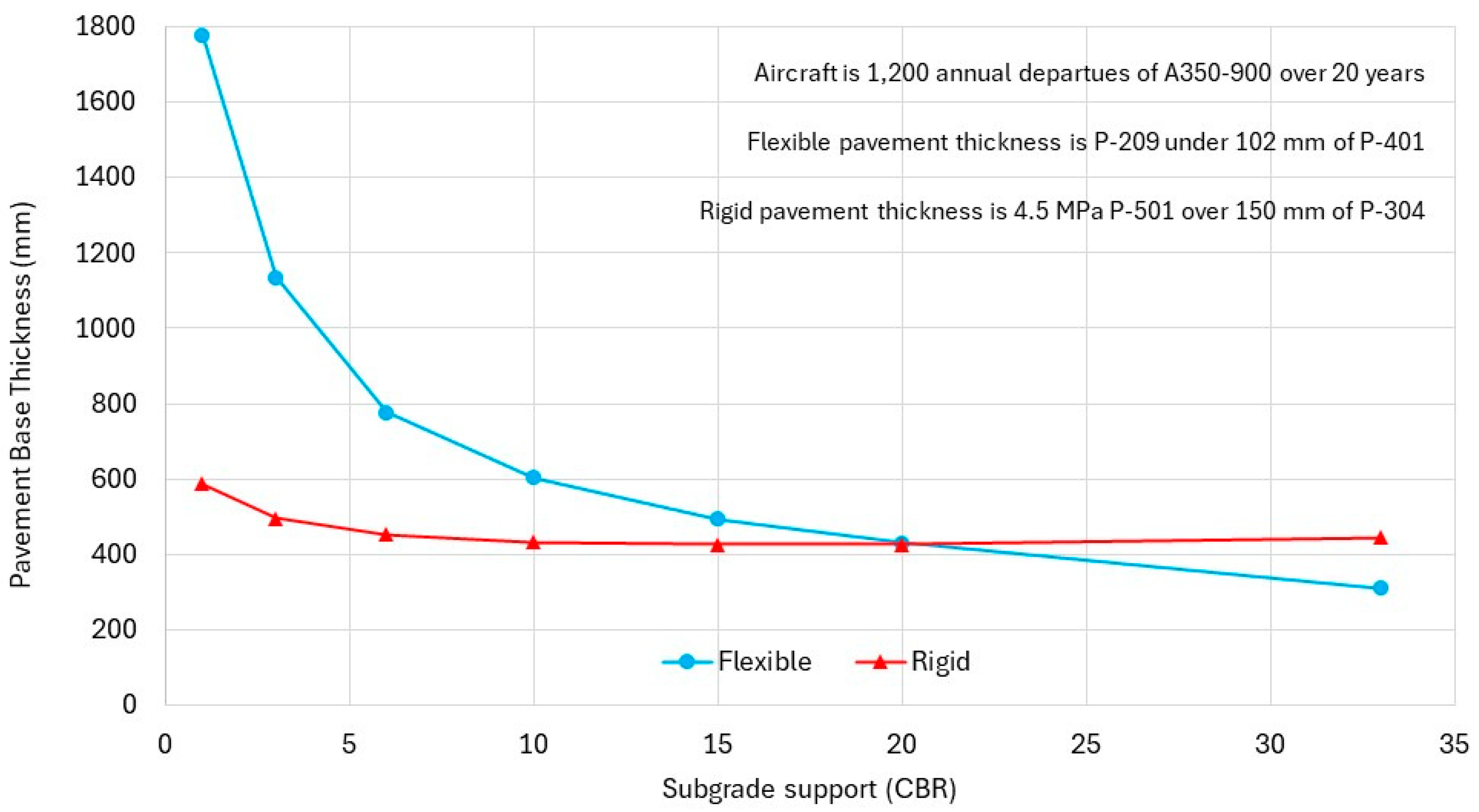
In the 1970s, when ACN–PCN was developed, the practical calculation of ACN was usually performed using charts, with the subgrade bearing capacity and aircraft weight varying, but for a fixed tire pressure, as shown in the example in Figure 1. Rather than a continually varying ACN across all possible CBR values, subgrades were categorized and a representative CBR value was adopted for each category [25]:
  • Category A. High strength. Represented as CBR 15;
  • Category B. Medium strength. Represented by CBR 10;
  • Category C. Low strength. Represented by CBR 6;
  • Category D. Ultra-low strength. Represented by CBR 3.
These subgrade categories remain in the current ACN–PCN system today. The representative values generally reflect the range of CBR values that are generally adopted for pavement thickness determination, with values below CBR 3 generally being improved prior to pavement construction and higher strength subgrades generally categorized with a capped value of CBR 15 (Australia) or CBR 20 of fine-grained soils and CBR 33 for gravelly subgrades (USA) [30].
Similar to the subgrade category simplification, the ACN–PCN system also categorized the tire pressure limits. The limits were (and remain) inherently empirical, in that there is no rational or design-based approach for assessing the allowable tire pressure for any given pavement surface, nor for quantifying the risk of exceeding that limit. In 2008, increases in the tire pressure limits were proposed by aircraft manufacturers [3]. In 2013, the proposed increase in the categorical tire pressure limits of the ACN–PCN system was approved [31]. Table 1 provides the original and revised tire pressure limits. This change allowed an increase in aircraft tire pressure from 1.50 MPa to 1.75 MPa to operate on airports with a Category X tire pressure limit. This affected over 40% of runways around the world at that time [32] and was supported by only minimal physical testing for relative rut resistance, at an outdoor test track in southern France during winter [33]. Consequently, the justification for these changes has been questioned [34] but they are now well-established and accepted as part of the ACN–PCN system. Some ICAO member states, such as Australia, prefer to publish an actual aircraft tire pressure limit rather than a category [35] and this reflects the common use of chip seals [36] for runway surfacing in regional parts of Australia [37].
The full PCN description for any given runway is a multi-element expression, such as the example in Equation (1). The main element is the number against which the ACN is compared. It is intended to protect the pavement structure from overload, primarily based on permanent subgrade deformation, also known as pavement rutting. The tire pressure limit is secondary, is compared to the operating tire pressure of the aircraft, and is intended to protect the surface from high near-surface stress. For an aircraft to operate in an unrestricted manner, the ACN must not exceed the PCN and the aircraft tire pressure must not exceed the tire pressure category or limit. When operating in an unrestricted manner is not permitted, either because of a higher ACN number or a higher tire pressure, a pavement concession must be sought by the aircraft operator and granted (or denied) by the airport owner or manager.
PCN 58/F/A/X/T
where:
58 is the numerical element against which the ACN is compared.
F is to indicate a Flexible pavement, rather than R for Rigid.
B is the category of subgrade category detailed above.
X is the tire pressure limit category (Table 1).
T is to indicate a technical assessment rather than a U for a usage-based assessment.
Unlike the ACN of an aircraft, the PCN of a runway is more open to interpretation. The optional usage-based assignment of the PCN effectively allows an airport to assign any PCN desired to any given runway. If an over-rating results in accelerated pavement damage, the airport is responsible for rectifying that. In contrast, in the USA, the FAA requires the use of a standardized and prescriptive method of PCN determination, based on software known as COMFAA [13]. This ensures that all airports in the USA have a consistent approach to their aircraft pavement strength rating and minimizes the risk of accelerated pavement deterioration.
The ACN–PCN system generally applies to pavements supporting critical aircraft with a mass of 5700 kg and above. For pavements that are designed for aircraft below that weight, a 5700 kg or lower total aircraft mass restriction is generally applied. That reflects the fact that most aircraft with a weight of 5700 kg or below have only a single wheel in each of the two main aircraft gears. For single-wheeled aircraft, the depth of pavement makes no difference to the relative effect of the aircraft because there are no other wheels for that single wheel to interact with. Consequently, for aircraft with a single main gear wheel, there is no practical benefit of determining an ACN, compared to a simple aircraft weight limit.

3.2. New Strength Rating System

As stated above, to reduce the occurrence of minor contradictions between pavement thickness determination and pavement strength rating, ICAO developed a new pavement strength rating system, known as ACR–PCR. The new system is due to be implemented by member states in November 2024 [18] although some member States have already declared a delay to the transition.
The ACR–PCR system is designed to operate and function in the same way that the ACN–PCN system has operated since 1981. That is, every aircraft will have an ACR value at a given aircraft weight and subgrade support, and this ACR will be compared to the PCR assigned to a given pavement. Consistent with ACN–PCN, when the ACR exceeds the PCR or the assigned tire pressure limit is exceeded by the aircraft tire pressure, a pavement concession is required. Despite the apparent similarities in the two systems, the ACR–PCR system includes significant changes [38].
  • Strain is used as the relative damage indicator, rather than deflection;
  • All wheels are considered explicitly, rather than being converted to an equivalent single wheel;
  • Actual pavement materials and composition are considered explicitly, rather than being converted to a standard composition;
  • Load repetitions, tire pressures, and pavement structures are more comparable to typical modern airport pavement structures;
  • Elastic modulus is used as the subgrade bearing capacity characteristic, replacing CBR for flexible pavements and the modulus of subgrade reaction (k-value) for rigid pavements;
  • Rigid and flexible pavement subgrade categories use the same elastic modulus ranges and characteristics values for subgrade characterization.
The term ACR–PCR was adopted to avoid confusion with ACN and PCN values [17]. Furthermore, the ACR is defined as twice the equivalent wheel load in hundreds of kilograms, rather than in tones. This means that ACR values generally range from 50 to 1000, compared to ACN values, which generally range from 5 to 100. This change was also designed to avoid confusion between the two systems [15].
For rigid pavements, a stress-to-strength ratio is used to determine ACR values for aircraft, so the number of traffic repetitions is not relevant. However, for flexible pavements, 36,500 passes of the aircraft are used to calculate the ACR [16]. That is an increase from the 10,000 passes used in ACN–PCN and is intended to reflect the increase in aircraft traffic at airports. However, this remains an arbitrary value because many runways are exposed to much higher traffic loadings. For example, the busiest airport in the world by aircraft movements in 2023, was Atlanta in the USA. This is based on the 775,000 annual movements at Atlanta airport [39], assuming equal distribution across the five runways. Assuming a pavement life of 20 years [30] that is over 3,000,000 passes of a runway cross-section, which is 82 times greater than the 36,500 adopted by ACR–PCR. Despite this, standardization is necessary, but a high number of passes would have been more representative of most major international airports.
The standard wheel load, to which other landing gear loads are converted, now has a 1.50 MPa tire pressure to better reflect large modern aircraft, compared to the 1.25 MPa tire pressure used to calculate ACN values [16]. The flexible standard pavement structure also has greater asphalt thickness and for flexible pavements that now depends on the number of wheels in the landing gear being considered. Table 2 shows the standard flexible pavement structures used in ACN–PCN and in ACR–PCR. For rigid pavements, the sub-base is now explicitly considered under ACR–PCR, whereas the effect of the sub-base was combined with the subgrade support condition, expressed as a k-value, under ACN–PCN. The rigid pavement structure is not affected by the number of wheels in the landing gear, as shown in Table 3.
The subgrade categories have also been adjusted to be the same for rigid and flexible pavements [17] and now correspond to subgrade categories used in France for road and highway pavement design [15]. The current and new subgrade categories are summarized in Table 4. For simplicity, equivalent CBR values are shown, even though ACR–PCR uses elastic modulus as the subgrade characteristic for ACR calculation. Figure 2 compares the subgrade categories, also as equivalent CBR values, and highlights the representative values used for each category in the respective systems. Figure 2 also highlights the equivalent CBR values that will necessitate airports changing from one subgrade category to another, such as CBR 5, 9, 13, and 14.
Furthermore, as stated above, the ACR–PCR system now uses the elastic modulus of the subgrade (expressed in MPa) to characterize subgrade bearing capacity. This better reflects the input into modern pavement thickness design software. Furthermore, the use of elastic modulus for both rigid and flexible pavement types avoids the need to estimate k-values for rigid pavements, which simplifies the ACR–PCR system for rigid pavements.
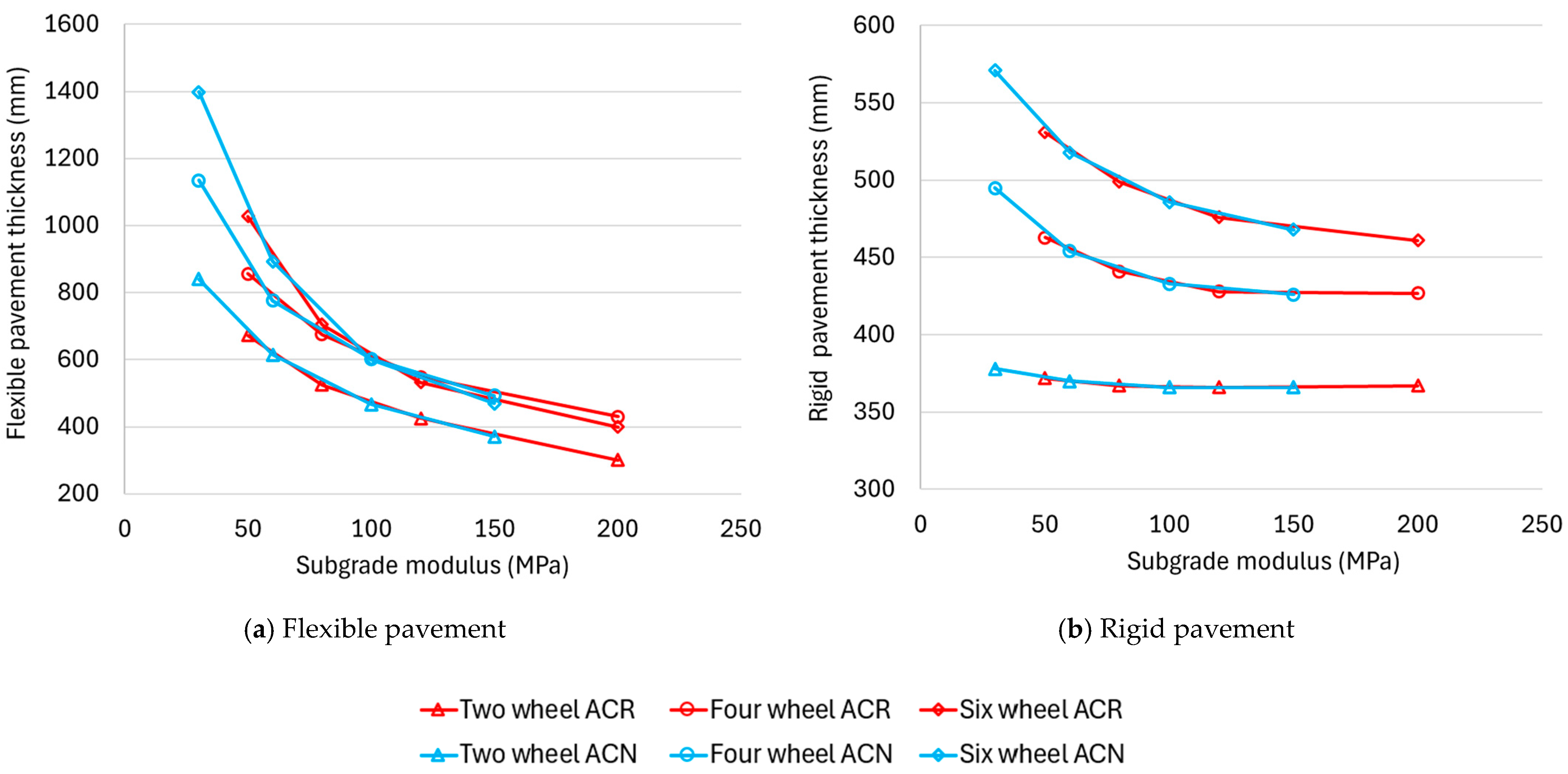
The ACR–PCR indicator of relative damage caused by different aircraft is vertical strain at the top of the subgrade, instead of maximum deflection at the top of the subgrade. Furthermore, the layered elastic models in FAARFIELD [8] are used to calculate the magnitudes of strain, rather than the simpler (Boussinesq) models used in COMFAA. This change reflects the more sophisticated computer power that is now readily accessible and greatly reduces the potential for anomalies between pavement thickness determination and strength rating. However, it means that the relationship between ACN and ACR is not fixed. In fact, the ratio of ACR to ACN for any given aircraft, pavement type, and subgrade category varies from approximately 7.5 to 12.5, as shown in Figure 3.
The change from ACN–PCN to ACR–PCR includes many improvements in the strength rating of aircraft pavements. The adoption of consistent and elastic modulus-based values for subgrade characterization for both flexible and rigid pavements is a good simplification and aligns strength rating with modern airport pavement thickness design practices. Similarly, the changes to the representative rigid and flexible pavement structures, as well as the aircraft traffic loadings, are more representative of typical airport pavement design scenarios, and this can only reduce anomalies between pavement strength rating and pavement thickness design. However, the adoption of strain as the indicator of relative damage caused by different aircraft rather than deflection, the avoidance of the equivalent aircraft concept by considering all the aircraft in the traffic loading, and the use of layered elastic methods for the calculation of critical damage indicators at critical locations with the pavement are the changes with the greatest potential to reduce anomalies between pavement design and pavement strength rating. The result is a modernized strength rating system that is far more aligned with the methods used in contemporary pavement thickness determination, which is a scientific improvement and provides many practical advantages.
Despite these improvements, some have criticized the change from ACN–PCN to ACR–PCR because it places a change-management burden on most airports around the world but provides no improvement in safety or operational efficiency. Consequently, some promoters of the change have made claims that ACR–PCR will provide benefits that are not realistic. For example, it has been claimed or implied that ACR–PCR will
  • Increase the knowledge of pavement thickness, material characteristics, and bearing capacity [40];
  • Reduce greenhouse gas emissions [40];
  • Prevent underestimation of pavement strength that is associated with ACN–PCN [40,41];
  • Result in an extended pavement design life [42];
  • Provide reduced pavement thicknesses for new pavement construction [40];
  • Improve pavement life prediction [40,41,43];
  • Provide more sustainable airport pavements [42,43].
In reality, it is not possible for a pavement strength rating system to increase the knowledge of the pavement thickness, material characteristics, or bearing capacity of the pavement owner. The knowledge of the pavement characteristics is a function of historical and contemporary design and construction records, as well as any investigation and testing results. A strength rating system cannot change the existence (or not) of those factual information sources. Furthermore, reduced greenhouse gas emissions, extended pavement design life, and reduced pavement thickness all relate to the avoidance of underestimated pavement strength ratings, by removing conservativism in historical pavement thickness design methods. However, ACR–PCR (just like ACN–PCN) is not (and was not) a pavement design method [16]. That is, a pavement that is designed for a specific aircraft will be equally strong enough to support that aircraft, no matter whether it is subsequently strength-rated by ACN–PCN or by ACR–PCR. The strength, structural life, predictability, and embodied greenhouse gas emissions associated with that pavement will be no different under ACR–PCR than it was under ACN–PCN. Similarly, the sustainability of that pavement will be unaffected by the strength rating system that is adopted for the management of its aircraft traffic loadings. Any claim that ACR–PCR will provide stronger, thinner, more sustainable, lower carbon content, or more predictable aircraft pavement structures is simply not true.
In addition to these unreasonable claims regarding safer, more efficient, and more predictable airport pavements under the ACR–PCR system, the new system also includes some changes that are not optimal, and some elements fail to incorporate additional potential benefits. These sub-optimal protocols and missed opportunities are discussed in detail below and include
  • Representative subgrade characteristics;
  • The number of subgrade categories;
  • Tire pressure limits for surface protection;
  • Light aircraft provision;
  • The rational basis for strength rating.

4. Potential Improvements to ACR–PCR

4.1. Representative Subgrade Characteristic

As shown in Figure 2, there are new limits and representative values for the subgrade bearing capacity associated with the transition from ACN–PCN to ACR–PCR. Under ACR–PCR, there is also consistency between characteristic subgrade bearing capacity values for flexible and rigid pavements, which is an improvement. Furthermore, the transition to layered elastic methods for ACR calculation, for consistency with contemporary pavement thickness determination software, means that an elastic modulus is a new characteristic used to represent different subgrades [16]. The transition to elastic modulus as the subgrade bearing capacity characteristic is supported, and the simple 10 times CBR provides for a convenient, albeit approximate, conversion for those that prefer to continue to think about subgrade support in CBR, which is how it is commonly measured in the laboratory [7,30]. The alignment of flexible and rigid subgrade bearing limits and representative values is also supported, as this simplifies the strength rating system, particularly for airports with both flexible and rigid runway pavements in close proximity, because it is reasonable to expect both to have the same subgrade category for pavement strength rating.
Despite these improvements, the change in subgrade category limits and representative values is a different matter. First, there is the potential to confuse airports, particularly those that will change the subgrade category when they transition from ACN–PCN to ACR–PCR. That includes those with an actual subgrade value equivalent to CBR 5, CBR 9, CBR 13, and CBR 14. The technical or operational benefit associated with aligning the representative subgrade support values to those used in French road pavement design methods [15] is questionable. Furthermore, as stated above, airport pavement thickness determination is generally performed over the range of CBR 3 to CBR 15 in Australia [7] and of CBR 3 to CBR 20 in the USA [30]. For subgrades with lower bearing capacity, improvement by stabilization or deep filling is common, allowing a CBR 3 or better value to be used in the design and to provide a platform able to support construction vehicles [7]. For subgrades that exceed CBR 15 (Australia) and CBR 20 (USA), a cap is usually placed on the value used for pavement thickness determination [30]. This upper-value capping reflects the minimum practical pavement thickness that should be provided for practicality and constructability. It also acknowledges that the effect of subgrade bearing capacity on flexible pavement thickness is greater at lower CBR values than at higher CBR values, as shown in Figure 4. Figure 4 also shows a similar trend for rigid pavements, with an actual increase in required slab thickness at subgrade support values above CBR 10, which is an illogical anomaly of FAARFIELD for some dual and dual-tandem wheeled aircraft. The greater influence of subgrade support on flexible pavements, compared to rigid pavements, is well established [7] and is also clear in Figure 4.
The consequence of the change in representative subgrade support values associated with the transition to ACR–PCR, towards higher equivalent CBR values than those used for ACN–PCN, is to reduce the ability of the strength rating system to represent the significantly greater level of aircraft wheel interaction effects for pavements with low subgrade bearing capacity. This is because the difference between the actual pavement thickness and the representative or standard pavement thickness will be greater than it would have been under ACN–PCN. For example, under ACN–PCN, subgrade category D was represented by CBR 3 and represented all subgrades up to and including CBR 4. Given the practically viable minimum design subgrade support is CBR 3, the maximum difference was when CBR 3 was used to represent an actual CBR 4 subgrade. Using FAARFIELD for the A350-900, this is a difference in pavement thickness, and therefore the potential degree of wheel interaction, of 1135 mm representing 975 mm, which is 160 mm, or a 14% thicker pavement base, resulting in only a minor and over-estimated potential for wheel interaction compared to the actual pavement. In contrast, under ACR–PCR, subgrade D represents all of the subgrade support levels of 50 MPa (CBR 5) and below, by a modulus of 50 MPa (CBR 5). For a pavement with an actual subgrade design modulus of 30 MPa (CBR 3), a difference in A350-900 pavement base thickness of 858 mm representing the wheel interaction potential of an 1135 mm thick pavement base, which is a 277 mm, or a 32% thinner pavement. This will significantly underestimate the potential for wheel interaction at subgrade depth. The impact of the overall increase in representative subgrade bearing capacity characteristics under ACR–PCR is less for rigid pavements because of the reduced effect of subgrade bearing capacity on rigid pavement thickness, compared to flexible pavement thickness. This is shown in Figure 5, which was generated in FAARFIELD, so uses the elastic modulus as the subgrade bearing capacity characteristic.
For countries with significant areas of low soil strength, represented by subgrade category D under ACN–PCN, the new subgrade category D in ACR–PCR will not represent the significant wheel interaction that will occur at the subgrade level of flexible pavements, associated with very low subgrade bearing capacity levels. Australia is an example of a country with old and generally low-bearing capacity soils [44], in combination with approximately 98% flexible pavements making up the airport pavement asset base [11]. Countries like Australia will be adversely affected by the change in subgrade category limits and representative values associated with ACR–PCR.

4.2. Number of Subgrade Categories

Further to the above discussion regarding the subgrade categories, limits, and representative values, the actual need for subgrade categories is also questioned. As stated above, the representation of the various subgrade categories each by single modulus or CBR value creates the potential for errors in the degree of represented wheel interaction at depth. Given that one of the aims of the transition from ACN–PCN to ACR–PCR was to avoid anomalous differences between design and strength rating, such differences should have been avoided whenever practically possible.
In the case of subgrade bearing capacity, the category-based approach was necessary when ACN–PCN was developed in the late 1970s. That is because, at that time, the mathematics required to calculate the interaction between aircraft wheels on a landing gear was performed manually and was time-consuming. Consequently, most ACN values were calculated by a formula or from a simple graph, such as the example in Figure 1. Similarly, routine pavement design was performed using charts or nomographs published by local authorities, such as the FAA [6]. In fact, it was not until 2002 that the FAA made the software known as COMFAA [13] available for ACN calculation, along with LEDFAA in 2014 for pavement thickness determination [45]. Because of the different degrees of wheel interaction for pavements of different thicknesses, multiple formulae of charts were required for different degrees of subgrade support. To simplify the publication of formulae or charts for routine ACN calculation, the four subgrade categories were established to span the range of reasonable subgrade bearing capacity levels expected in common pavement design methods.
In contrast, contemporary pavement thickness determination is predominantly performed in software, with APSDS [46], Alize-Airport [47], and FAARFIELD [8] being common examples. This software generally uses subgrade modulus values for subgrade support characterization, generally rounded to the nearest 10 MPa, equivalent to a whole CBR value. Once this subgrade elastic modulus used for design purposes is known, it could easily be entered into software for ACR calculation. The software known as ICAO-ACR [48] has already been made available by the FAA for the calculation of ACR values. Once the aircraft and pavement are selected, the software generates an ACR value for each of the four subgrade categories almost instantly. However, it would be just as reasonable to calculate ACR values for any other subgrade modulus, from the equivalent of CBR 3 to CBR 15, with lower and higher CBR-equivalent values combined with the minimum and maximum values, respectively. Alternatively, the user could enter their subgrade modulus and ICAO-ACR could generate an ACR value for a rigid and flexible pavement at that subgrade modulus value only. Either way, the calculation time would remain almost instant because the time-consuming manual calculations required in the 1970s are now performed so quickly by the software.
By increasing the precision of the subgrade support characteristic, from a broad category to the actual modulus of CBR value, anomalies resulting from differences in the aircraft wheel interaction, due to the different depths of the subgrade under the different pavement thicknesses required, would be further reduced. Given that reducing such anomalies was one aim of the transition from ACN–PCN to ACR–PCR, it would be advantageous if it is practically implementable. Contemporary computer power and the cessation of the need to manually determine wheel interactions at depth with laborious manual mathematics enables ACN (and ACR) values to be determined almost instantly. Consequently, there is no barrier to adopting actual subgrade support modulus or CBR value, which should be known from pavement thickness determination anyway. The only change to the ACR–PCR system required to implement this improvement is the replacement of the subgrade category with the actual subgrade elastic modulus value and the format for reporting aircraft ACR values by aircraft manufacturers in the airport planning manuals.

4.3. Tire Pressure Limits for Surface Protection

The tire pressure limit element of ACN–PCN, intended to protect flexible pavement surfaces from over-stress, does not change with the transition from ACN–PCN to ACR–PCR. That is, the tire pressure limit remains a category of acceptable tire pressure, which is compared to the tire pressure of the main landing gear of the aircraft, as detailed in Table 1.
Limiting tire pressure is a simple approach, although it does not capture the interaction between tire pressure and wheel load when determining the relative damaging stresses and strains in flexible airport pavement surfaces. For example, a military jet with 2300 kPa tire pressure may only have a relatively modest wheel load. However, under ACR–PCR (and ACN–PCN), these are considered to be more damaging to an asphalt surface than a B777-300ER (29.3 tones per wheel at 1524 kPa) or an A350-900 (34.1 tones per wheel at 1662 kPa) because of the higher tire pressure. This is not actually the case.
White [29] determined the relative damage caused to asphalt surfaces by different aircraft, using octahedral shear stresses induced by braking and turning aircraft as the indicator of relative damage [49]. It was concluded that an index, called the Wheel Classification Number (WCN) based on equal octahedral shear stress, should be used to replace the tire pressure limit. The importance of wheel load, in combination with tire pressure, is shown in Figure 6, and the recommended WCN index values for different categories of wheel load and tire pressure are in Table 5.
The retention of the simple tire pressure categories and limits, rather than the adoption of a WCN or a similar index, based on both tire pressure and wheel load, is a missed opportunity for improving the airport pavement strength rating system. In light of the irrelevance of tire pressure on its own, combined with the general absence of surface distress from contemporary pavement design methods [7], it is recommended that either a WCN (or similar) be adopted, or the otherwise meaningless tire pressure limited be removed from ACR–PCR.

4.4. Light Aircraft Provision

The strength rating of pavements for light aircraft is generally not an issue for rigid pavements, because even the minimum practically constructable concrete thickness is likely to be adequate for all light aircraft. However, it is an issue for flexible pavements, which are far more common for airports that cater to light aircraft, either for flight training or in remote and regional areas [7].
The ACN–PCN method of pavement strength rating applies to pavements intended to support aircraft exceeding 5700 kg in total weight. That is, it does not apply to aircraft up to 5.7 tones [5]. Pavements for the lighter aircraft are instead rated using a simple weight limit, usually 5700 kg, or are considered to be unrated. The reason for this is that most aircraft with a total weight of up to 5700 kg are supported by single main gear wheels. Recalling that the different subgrade categories are primarily to reflect the different interaction between the multiple wheels on larger aircraft, the pavement thickness, and therefore the subgrade category, is not important for single wheeled aircraft, because single wheels can not interact with other wheels. Consequently, for single-wheeled aircraft, a total aircraft mass is just as effective as a more complex ACN (or ACR) in representing the relative amount of pavement damage caused by the aircraft.
The first challenge with this system, which is not changing under ACR–PCR, is the potential for confusion between a 5700 kg rating, a pavement that is unrated, and a pavement that leaves the element of the aerodrome information publication blank. A review of smaller airport entries from the Australian aerodrome information publication [50] shows examples of all three of these entries. There are subtle differences between a blank space where the rating should be, a declaration of unrated, and a 5700 kg rating. However, in practice, these all have the same effective outcome, which is a default 5700 kg limitation. The publication of the strength rating for these light aircraft pavements should be made clear, so there is consistency and clarity.
The second challenge for these light pavements is that the FAA’s FAARFIELD [8] software, which is the most accessible and most commonly used airport pavement thickness method in the world, does not cater to pavements intended only for these light aircraft. The simplest and thinnest flexible pavement that can be considered in thickness design mode in FAARFIELD is 102 mm of P-401 (asphalt concrete) over 152 mm of P-209 (crushed rock base). For a standard 20-year design life and a low 1200 annual departures, the weight of a single-wheeled aircraft that can be supported by this minimum pavement is 7.4 tones up to 26 tones, depending on the subgrade bearing strength, as detailed in Table 6. Consequently, there is a gap between the lowest-strength pavements that can be designed using FAARFIELD and pavements that are considered to be too low in strength for the ACR–PCR method to apply. Furthermore, the gap is larger for pavements with higher levels of subgrade bearing capacity, because the minimum pavement thickness can support a much larger aircraft when the subgrade support is high. As an example of this challenge, for a typical subgrade with modulus 80 MPa (CBR 8), the minimum 256 mm thick flexible FAARFIELD pavement can support single-wheel aircraft up to 9.9 tones. There is no effective way to design and rate a pavement, using FAARFIELD, for an aircraft between 5700 kg and 9900 kg. Similarly, for a 200 MPa subgrade (CBR 20), this gap increases to between 5700 kg and 26,000 kg. There are many aircraft that fall into this range, including Cessna Citation V, Shorts 360, BeechJet-400, and military jets such as the F-16 and F/A-18. FAARFIELD must be amended to allow reduced thicknesses and removal of the currently mandatory asphalt surface, for the design of flexible pavements for light aircraft, which rarely have two layers (100 mm) of asphalt concrete surface [7] and instead make significant use of sprayed seal or chip seal surfaces [36]. The alternate would be to increase the aircraft mass below which the ACR–PCR system does not apply, to reduce the gap between minimum pavement design and maximum aircraft weight-based rating.
The third challenge is that a two-wheeled aircraft can be heavier than 5700 kg, but can cause the same amount of damage as the 5700 kg aircraft supported by a single wheel. This is difficult to quantify because, as detailed above, the minimum thicknesses of flexible pavement layers in FAARFIELD result in the thinnest practical pavement being adequate for aircraft much heavier than 5700 kg. However, Figure 7 shows the weight of single and dual-wheel aircraft that can use the minimum thickness FAARFIELD pavement, based on the ACR–PCR characteristic subgrade support levels. The dual-wheeled aircraft were 43% to 86% heavier than the single-wheeled aircraft, for the same minimum pavement and the same subgrade bearing capacity. If the 5700 kg aircraft mass limit for ACR–PCR was increased to the minimum weight that can be designed for in FAARFIELD, 26,000 kg, then a 40,400 kg aircraft on dual wheels could also be accommodated on the same pavement. Given the significant number of aircraft that have dual wheels and a weight of up to 40.4 tonnes, excluding these aircraft from the ACR–PCR is not reasonable. Consequently, the only viable option is to amend FAARFIELD so that pavement thicknesses can be determined for all aircraft that exceed the current 5700 kg non-PCR strength rating approach. That would mean that the instances of heavier dual-wheel aircraft not being permitted to operate on a pavement that they would not in fact overload would be limited to the few aircraft that have dual wheels and a weight of approximately 8000 kg, depending on the subgrade support level. There are only a few dual aircraft with such a low operating weight, meaning this anomaly associated with 5700 kg restrictions will be minimized.

4.5. Rational Basis for Strength Rating

Consistent with the ACN–PCN system, ACR–PCR provides for two bases of strength rating: technical (T) and usage-based (U) [16]. However, under ACR–PCR, the method for determining a technically based PCR is a prescriptive protocol [16] that is similar to the PCN calculation method currently required by the FAA for airports in the USA, under ACN–PCN [12]. This leaves airports with a binary choice between a highly prescriptive approach and an informal approach that might be viewed as less valid.
Somewhere in between these two extremes is a process for determining a PCR value for a runway that is based on pavement design and evaluation, whether finite element based, layered elastic based, or otherwise, that determines that a pavement is adequate for a certain aircraft traffic loading and then assigns a PCR value that is equal to the highest ACR value associated with the aircraft in the designed or evaluated aircraft traffic load. This is a rational approach that is far more technical than a usage-based assessment but does not necessarily use the formal and prescriptive protocols of the technical assessment under the new ICAO guidance [16]. It has previously been suggested that most airports will follow some form of rational approach that does not comply with the ICAO technical rating protocol [15] and consequently, the absence of a third rational (R) basis of strength rating is a missed opportunity under the new ACR–PCR system.

5. Conclusions

Based on a critical review of the new international airport pavement strength rating system, it was concluded that a number of improvements have been made, including the alignment of rigid and flexible pavement subgrade support characteristics and category values, as well as more representative pavement structures and aircraft traffic frequencies. However, the new system misses some important opportunities and includes some questionable and valueless changes, including the trend to higher representative subgrade characteristic values, the retention of subgrade support categories rather than actual design subgrade support characteristic values, and the retention of a simple tire pressure category limit approach for surface protection. Furthermore, the single wheel-based light aircraft provisions and the absence of a rational approach to strength rating that is substantially better than a usage-based approach, but which does not necessarily follow the formal technical rating protocol, are also missed opportunities. Although the new strength rating system will significantly decrease the occurrence of anomalous differences between the design of aircraft pavements and their subsequent strength rating, it retains a number of issues that should be improved in the future. Despite this, and in light of the fact the current ACN–PCN system was in place for over 40 years without significant change, it is expected that ACR–PCR will be in place for many years and that airports should prepare for its imminent introduction, regardless of the associated limitations. A strategy to simplify that transition, particularly for smaller airports, is now required to improve implementation efficiency.

Funding

This research received no external funding.

Conflicts of Interest

The author declares no conflicts of interest.

References

  1. Fabre, C.; Balay, J.; Lerat, P.; Mazars, A. Full-scale aircraft tire pressure test. In Proceedings of the Eight International Conference on the Bearing Capacity of Roads, Railways and Airfields, Urbana-Champaign, IL, USA, 29 June–2 July 2009; pp. 1405–1413. [Google Scholar]
  2. Roginski, M.J. Effects of aircraft tire pressures on flexible pavements. In Proceedings of the Advanced Characterisation of Pavement and Soil Engineering Materials Conference, Athens, Greece, 20–22 June 2007; pp. 1473–1481. [Google Scholar]
  3. Rodway, B. Asphalt deformation due to high tyre pressure. In Proceedings of the FAA Airport Pavement Working Group Annual Meeting, Federal Aviation Administration, Atlantic City, NJ, USA, 21–23 July 2009. [Google Scholar]
  4. Anstee, H.; White, G. Defining the gap associated with compacting and proving granular layers and fills for airport pavement construction. In Proceedings of the International Conference on Transport and Development, Seattle, WA, USA, 31 May–3 June 2022. [Google Scholar]
  5. International Civil Aviation Organization. Aerodrome Design Manual: Part 3, 2nd ed.; ICAO 9157; International Civil Aviation Organization: Montreal, QC, Canada, 1983. [Google Scholar]
  6. Federal Aviation Administration. Airport Pavement Design and Evaluation; AC 150/5320-6C; Federal Aviation Administration: Washington, WA, USA, 1978. [Google Scholar]
  7. Australian Airports Association. Airport Practice Note 12—Airfield Pavement Essentials; Australian Airports Association: Canberra, ACT, Australia, 2017; Available online: www.scribd.com/document/596050238/Australian-Airports-Asscociation-2017-Manual-Airfield-Pavement-Essentials (accessed on 1 January 2023).
  8. Federal Aviation Administration. FAARFIELD 2.1.1; Airport Design Software FAARFIELD 2.1.1; Federal Aviation Administration: Washington, WA, USA, 22 December 2023. Available online: www.airporttech.tc.faa.gov/Products/Airport-Safety-Papers-Publications/Airport-Safety-Detail/ArtMID/3682/ArticleID/2841/FAARFIELD-20 (accessed on 11 August 2024).
  9. Brill, D.R.; Kawa, I. Advances in FAA pavement thickness design Software: FAARFIELD 1.41. In Proceedings of the International Conference on Highway Pavements and Airfield Technology, Philadelphia, PA, USA, 27–30 August 2017. [Google Scholar]
  10. Civil Aviation Safety Authority. Part 139 (Aerodromes) Manual of Standards 2019: Amendments to F2024L00292; Civil Aviation Safety Authority: Canberra, ACT, Australia, 13 March 2024. Available online: www.legislation.gov.au/F2019L01146/latest/text (accessed on 11 August 2024).
  11. White, G.; Farelly, J.; Jamieson, S. Estimating the value and cost of Australian aircraft pavement assets. In Proceedings of the International Airfield and Highway Pavement Conference, American Society of Civil Engineersa, Virtual, 8–10 June 2021. [Google Scholar]
  12. Federal Aviation Administration. Standardized Method of Reporting Aircraft Pavement Strength—PCN; Advisory Circular 150/5335-5C; Federal Aviation Administration: Washington, WA, USA, 14 August 2024. [Google Scholar]
  13. Federal Aviation Administration. COMFAA 3.0; Federal Aviation Administration, 14 August 2014. Available online: www.airporttech.tc.faa.gov/Products/Airport-Pavement-Software-Programs/Airport-Software-Detail/ArtMID/3708/ArticleID/10/COMFAA-30) (accessed on 11 August 2024).
  14. Tipnis, M.; Patil, M. Design program based PCN evaluation of aircraft pavements’. In Proceedings of the FAA World Wide Airport Technology Transfer, Galloway, NJ, USA, 5–7 August 2014. [Google Scholar]
  15. White, G. Practical implications for the implementation of the new international airport pavement strength rating system. In Proceedings of the 11th International Conference on the Bearing Capacity of Roads, Railways and Airfields, Trondheim, Norway, 28–30 June 2022; Volume 1, pp. 210–225. [Google Scholar]
  16. International Civil Aviation Organization. Aerodrome Design Manual: Part 3, 3rd ed.; ICAO 9157; International Civil Aviation Organization: Montreal, QC, Canada, 2022. [Google Scholar]
  17. Brill, D.R.; Garg, N. Airport Pavement Design and Evaluation Workshop—Introduction to FAARFIELD2.0 and ICAO’s ACRPCR System. In Proceedings of the International Airfield & Highway Pavements Conference, Austin, TX, USA, 12–14 June 2023. [Google Scholar]
  18. Honey, H.; Crislip, J. ICAO ACR-PCR Procedure of Reporting Airport Pavement Stregth. In Proceedings of the Fourth Meeting of the Asia/Pacific Aerodrome Design and Operations Task Force, Chiang Rai, Thailand, 10–13 January 2023; Available online: www.icao.int/APAC/Meetings/2023%20APADOTF4 (accessed on 11 August 2024).
  19. Deilami, S.; White, G. Review of reflective cracking in composite pavements. Int. J. Pavement Res. Technol. 2020, 13, 524–535. [Google Scholar] [CrossRef]
  20. Ahlvin, R.G. Origin of Developments for Structural Design of Pavement; In Technical Report GL91-26; US Army Corps of Engineers Waterways Experiment Station: Vicksburg, MS, USA, 1991. [Google Scholar]
  21. White, G.; Kelly, G.; Fairweather, H.; Jamshidi, A. Theoretical socio-enviro-financial cost analysis of equivalent flexible aircraft pavement structures. In Proceedings of the 99th Annual Meeting of the Transportation Research Board, Washington, WA, USA, 12–16 January 2020. [Google Scholar]
  22. Jamieson, S.; White, G. Defining Australian rigid aircraft pavement design and detailing practice. In Proceedings of the International Airfield and Highway Pavement Conference, American Society of Civil Engineers, Virtual, 8–10 June 2021. [Google Scholar]
  23. Jamieson, S.; White, G. Review of rigid aircraft pavement joint types, effectiveness, distress, maintenance and analysis. In Proceedings of the International Airfield & Highway Pavements Conference, Austin, TX, USA, 12–14 June 2023. [Google Scholar]
  24. International Civil Aviation Organization. About ICAO; International Civil Aviation Organization: Montreal, QC, Canada. Available online: www.icao.int/about-icao/Pages/default.aspx (accessed on 11 August 2024).
  25. International Civil Aviation Organization. Aerodrome Design and Operations; Annex 14, Volume 1, to the Conventions on International Civil Aviation; International Civil Aviation Organization: Montreal, QC, Canada, 2013. [Google Scholar]
  26. International Civil Aviation Organization. Member States; International Civil Aviation Organization: Montreal, QC, Canada; Available online: www.icao.int/about-icao/Pages/member-states.aspx (accessed on 11 August 2024).
  27. Armeni, A.; Loizos, A. Reporting the bearing capacity of airfield pavements using PCR index. NDT 2024, 2, 16–31. [Google Scholar] [CrossRef]
  28. Federal Highway Administration. Bridge Formula Weights; FHWA-HOP-19-028; Federal Highway Administration: Washington, WA, USA, 2019. Available online: https://ops.fhwa.dot.gov/freight/publications/brdg_frm_wghts/fhwahop19028.pdf (accessed on 11 August 2024).
  29. White, G. Shear stresses in an asphalt surface under various aircraft braking conditions. Int. J. Pavement Res. Technol. 2016, 9, 89–101. [Google Scholar] [CrossRef]
  30. Federal Aviation Administration. Airport Pavement Design and Evaluation; AC 150/5320-6G; Federal Aviation Administration: Washington, WA, USA, 7 June 2021. [Google Scholar]
  31. Roginski, M.J. ICAO update—Status of high tyre pressure revision to Annex 14. In Proceedings of the FAA Working Group Meeting, Federal Aviation Administration, Atlantic City, NJ, USA, 15–17 April 2013. [Google Scholar]
  32. Shepson, O. Boeing and Airbus tire pressure test programs. In Proceedings of the ALACPA Airport Pavement Seminar and FAA Workshop, Sao Paulo, Brazil, 26–30 October 2009. [Google Scholar]
  33. Fabre, C. The Airbus high tyre pressure test. Flight Airworth. Support Technol. 2011, 48, 2–9. [Google Scholar]
  34. White, G. Limitations and potential improvement of the aircraft pavement strength rating system. Int. J. Pavement Eng. 2017, 18, 1111–1121. [Google Scholar] [CrossRef]
  35. Civil Aviation Safety Authority. Strength Rating of Aerodrome Pavements; AC139.C-07; Civil Aviation Safety Authority: Canberra, ACT, Australia, 2021. Available online: www.casa.gov.au/rules/regulatory-framework/casr/part-139-casr-aerodromes#Guidancematerial (accessed on 13 August 2024).
  36. White, G. Spray seals for airports. In Proceedings of the 2nd International Sprayed Sealing Conference, Melbourne, VIC, Australia, 10–12 October 2010. [Google Scholar]
  37. White, G. Comparison of bituminous surface options for regional airport runway pavements. In Proceedings of the 8th International Conference Bituminous Mixtures and Pavements, Thessaloniki, Greece, 12–14 June 2024. [Google Scholar]
  38. Fabre, C. The ACR-PCR Method; International Coordinating Council of Aerospace Industries Association: Montreal, QC, Canada, 2019. [Google Scholar]
  39. Airports Council International. Top 10 Busiest Airports in the World Shift with the Rise of International Air Travel Demand; 14 April 2024. Available online: www.aci.aero/2024/04/14/top-10-busiest-airports-in-the-world-shift-with-the-rise-of-international-air-travel-demand (accessed on 11 August 2024).
  40. International Civil Aviation Organisation. Pavement Asset Optimisation of the Overall Lifecycle of Pavement for Mastering Airports Operations, Cost Efficiency and GHG Footprint; Working Paper WPA41-WP/269; International Civil Aviation Organisation: Montreal, QC, Canada, 2022. [Google Scholar]
  41. Fabre, C. Aircraft/pavement classification rating ACR-PCR. In Proceedings of the Central American and Caribbean Working Group (NACC/WG) Aerodromes and Ground Aids (AGA) Implementation Task Force Meeting, NACC/WG/AGA/TF/2, Mexico City, Mexico, 15–17 May 2024; Available online: www.icao.int/NACC/Documents/Meetings/2024/AGATF2/AGATF2-P02.pdf (accessed on 11 August 2024).
  42. Pavement Management Services. ACR-PCR: The New Airport Pavement Rating Method Explained; Pavement Management Services: Sydney, NSW, Australia; Available online: www.pavement.com.au/news/acr-pcr-the-new-airport-pavement-rating-method-explained#:~:text=The%20ACR-PCR%20system%20enhances%20pavement%20use%20and%20ensures,life%20cycle%20through%20predictive%20maintenance%20and%20usage%20optimisation (accessed on 11 August 2024).
  43. New Method to Report Pavement Strength (ACR-PCR); Webinar Presentation, 6 October 2022. Available online: www.easa.europa.eu/en/newsroom-and-events/events/new-method-report-pavement-strength-acr-pcr-webinar (accessed on 11 August 2024).
  44. Australia: State of the Environment 2021; Department of Climate Change, Energy, the Environment and Water: Canberra, ACT, Australia. 2021. Available online: https://www.dcceew.gov.au/science-research/soe (accessed on 12 August 2024).
  45. LEDFAA 1.3; Federal Aviation Administration, 4 March 2012. Available online: www.airporttech.tc.faa.gov/Airport-Pavement-OLD/Pavement-Design-and-Evaluation/Advanced-Pavement-Design/LEDFAA) (accessed on 12 August 2024).
  46. APSDS—Airport Pavement Design Software; Pavement Science. Available online: https://pavement-science.com.au/softover/apsds/ (accessed on 12 August 2024).
  47. Alize LCPC; Ifstar. Available online: www.alize-lcpc.com (accessed on 12 August 2024).
  48. Federal Aviation Administration. ICAO-ACR 1.4; Federal Aviation Administration: Washington, WA, USA, 16 March 2020. Available online: www.airporttech.tc.faa.gov/Products/Airport-Pavement-Papers-Publications/Airport-Pavement-Detail/ArtMID/3684/ArticleID/2838/ICAO-ACR-13 (accessed on 13 August 2024).
  49. White, G. Modification of the airport pavement strength rating system for improved protection of asphalt surfaces. Int. J. Pavement Eng. 2019, 20, 519–529. [Google Scholar] [CrossRef]
  50. Airservices Australia. Aeronautical Information Package; Airservices Australia: Canberra, ACT, Australia. Available online: www.airservicesaustralia.com/aip/aip.asp (accessed on 14 August 2024).
Figure 1. Example of an ACN chart for the B737-800.
Applsci 14 08491 g001
Figure 2. Flexible subgrade category ranges for ACN–PCN and for ACR–PCR.
Applsci 14 08491 g002
Figure 3. Relationship between ACR and ACN values for common aircraft.
Applsci 14 08491 g003
Figure 4. Flexible and rigid pavement thickness for A350-900 on different subgrade supports.
Applsci 14 08491 g004
Figure 5. Pavement thickness for A350-900 on different subgrade supports.
Applsci 14 08491 g005
Figure 6. Iso-octahedral shear stress and WCN index for different wheel loads and tire pressure (adapted from [29]).
Applsci 14 08491 g006
Figure 7. Allowance single and dual wheel aircraft mass on the minimum FAARFIELD pavement.
Applsci 14 08491 g007
Table 1. Tire pressure category limits.
CategoryOriginal Tire Pressure LimitsRevised Tire Pressure Limits
WUnlimitedUnlimited
X1.50 MPa1.75 MPa
Y1.10 MPa1.25 MPa
Z0.50 MPa0.50 MPa
Table 2. ACN–PCN and ACR–PCR standard flexible pavement structures.
LayerThickness under ACN–PCN SystemThickness under ACR–PCR System
For Aircraft with 1–2 WheelsFor Aircraft with 3 or More Wheels
Asphalt surface (P-401)75 mm76 mm127 mm
Crushed rock (P-209)150 mmAs requiredAs required
Uncrushed gravel (P-154)As requiredNot usedNot used
SubgradeInfiniteInfiniteInfinite
Table 3. ACN–PCN and ACR–PCR standard rigid pavement structures.
LayerThickness under ACN–PCN SystemThickness under ACR–PCR System
Concrete base (P-501)As requiredAs required
Crushed rock (P-209)Combined with subgrade200 mm
SubgradeInfiniteInfinite
Table 4. ACN–PCN and ACR–PCR flexible subgrade categories.
Subgrade CategoryACN–PCN SystemACR–PCR System
Nominal CBRCBR RangeNominal CBRCBR Range
A1513 and above2015 and above
B108–121210–14
C64–886–9
D34 and below55 and below
Note: elastic modulus (MPa) is commonly calculated as 10 × CBR.
Table 5. Wheel Classification Numbers (adapted from [49]).
Wheel Load (t)Tire Pressure (kPa)
<500500–750750–10001000–12501250–15001500–17501750–20002000–2250>2250
<5111416171819191920
5–10131719212223242424
10–15141821232426272727
15–20151922242627282931
20–25151923252728293031
25–30152023262829303233
30–35152024262830323234
>35152024262931323335
Table 6. Single-wheel aircraft mass for minimum FAARFIELD pavement thickness.
ACR–PCR Subgrade CategoryRepresentative Modulus Value (MPa)Allowable Aircraft Mass (Tonnes)
A20026.0
B12015.1
C809.9
D507.4
Disclaimer/Publisher’s Note: The statements, opinions and data contained in all publications are solely those of the individual author(s) and contributor(s) and not of MDPI and/or the editor(s). MDPI and/or the editor(s) disclaim responsibility for any injury to people or property resulting from any ideas, methods, instructions or products referred to in the content.

