Article

Artificial Intelligence Model Used for Optimizing Abrasive Water Jet Machining Parameters to Minimize Delamination in Carbon Fiber-Reinforced Polymer

by
Ioan Alexandru Popan
1,*,
Vlad I. Bocăneț
1,
Selver Softic
2,
Alina Ioana Popan
1,
Nicolae Panc
1 and
Nicolae Balc
1
1
Department of Manufacturing Engineering, Technical University of Cluj-Napoca, B-dul. Muncii, No. 103-105, 400641 Cluj-Napoca, Romania
2
CAMPUS 02, University of Applied Sciences, Körblergasse 126, 8010 Graz, Austria
*
Author to whom correspondence should be addressed.
Appl. Sci. 2024, 14(18), 8512; https://doi.org/10.3390/app14188512
Submission received: 29 July 2024 / Revised: 11 September 2024 / Accepted: 19 September 2024 / Published: 21 September 2024
(This article belongs to the Special Issue Advancement in Smart Manufacturing and Industry 4.0)

Abstract

:
This study introduces an artificial neural network (ANN) model for optimizing process parameters to reduce the chances of delamination in carbon fiber-reinforced polymer (CFRP) materials during abrasive water jet (AWJ) piercing. AWJ is a proper method for cutting CFRP. The initial step in this process is AWJ piercing, which creates entry holes in the material to facilitate further cutting operations. However, AWJ piercing is particularly challenging due to the high energy applied to the material. If it is not properly controlled, this high-energy impact can cause material delamination. Avoiding CFRP delamination is a critical aspect when expensive parts are processed with AWJ, particularly in the aerospace and automotive industries. This can compromise the CFRP workpiece, and this induces extra costs for rework. The ANN model was trained using backpropagation to predict delamination. It features a feed-forward architecture that balances model complexity and performance. Validation showed that the ANN model effectively predicted optimal process parameters, eliminating delamination in machined CFRP parts. This study underscores the potential of ANNs in enhancing AWJ piercing processes and provides a robust and reliable method of improving the quality of CFRP parts.

1. Introduction

Carbon fiber-reinforced polymer is a composite material known for its remarkable strength-to-weight ratio, rigidity, and resistance to fatigue and environmental degradation [1]. These properties make CFRP a material used across many high-performance applications, including the aerospace [2], automotive [3], sporting goods, and construction industries [4]. CFRP is composed of carbon fibers embedded in a polymer matrix, typically an epoxy resin. The carbon fibers provide high tensile strength and stiffness, while the polymer matrix protects the fibers and helps transfer loads between them [5,6]. This combination results in a composite that is not only lightweight but also very strong and durable [7,8]. The alignment of carbon fibers within the matrix can be tailored to optimize mechanical properties in specific directions, allowing for the design of components that meet demanding performance criteria [7,9,10].
In the aerospace industry, CFRP has revolutionized the design and manufacture of aircraft components. Its low weight contributes significantly to fuel efficiency and performance. This enables the creation of lighter, more efficient airframes and structural components [11]. The automotive industry has also embraced CFRP for its potential to reduce vehicle weight, which improves fuel efficiency and performance overall [8]. Luxury and high-performance cars frequently use CFRP for body panels, chassis components, and interior structures. CFRP is also the material of choice for high-performance equipment, such as bicycles, tennis rackets, and golf clubs [1].
The heterogeneous nature of CFRP, characterized by the distinct properties of its fiber and matrix components, makes the machining process more complex [5,12]. Unlike metals, CFRP does not deform plastically; instead, it tends to fracture, which can lead to various defects [7,13]. The most damaging issue is delamination, in which layers of the composite separate due to the stresses induced during machining [14].
Abrasive water jet (AWJ) machining has emerged as a promising technique for processing CFRP due to its ability to cut without inducing significant thermal stresses [15,16]. The principle of AWJ cutting is based on the use of high-pressure water combined with abrasive particles to precisely cut and shape various materials [17,18]. Figure 1 illustrates the AWJ processing principle. A high-pressure pump is used to pressurize water to extremely high levels, typically between 100 and 600 MPa [19]. This pressurized water is then directed through a small orifice, creating a focused, high-velocity jet of water. Once the high-velocity water jet is formed, abrasive particles, such as garnet, are introduced into the stream. This mixture is created in a mixing chamber where the abrasive particles are set into motion in the water jet [17,20]. The addition of abrasive particles significantly enhances the cutting capabilities of the water jet, allowing it to cut through tougher and thicker materials that pure water jets alone could not handle. The mixture of high-velocity water and abrasive particles exits through a focusing tube, forming the abrasive water jet [21,22]. When the AWJ is directed toward the material to be cut, the high kinetic energy of the abrasive particles hits the surface [23].
Abrasive water jet cutting (AWJC) offers many advantages over traditional cutting methods. It is highly versatile and capable of cutting a wide range of materials, including metals, composites, ceramics, glass, and stone [24]. AWJC is a cold-cutting process, which means that it generates no significant heat during the cutting operation. This is especially advantageous when cutting CFRP, as it eliminates the risk of heat-induced damage, such as thermal degradation, preserving the material’s integrity and mechanical properties [17,25,26]. AWJC offers good precision, allowing for intricate and complex shapes to be cut with high accuracy [27,28]. This level of precision is particularly beneficial for CFRP components used in aerospace, automotive, and other high-performance industries, where tight tolerances and detailed geometries are often required [3,29]. The AWJ produces clean and smooth edges on CFRP components. The narrow kerf width of AWJC results in minimal waste of material. This is particularly important for expensive materials like CFRP, for which reducing waste can lead to significant cost savings and more efficient use of resources [11].
The main process is AWJ cutting, in which internal and external contours are precisely machined [1,30]. The initial step is AWJ piercing, which creates entry holes in the material to facilitate further cutting and shaping operations. AWJ piercing is very challenging due to the high energy applied to the material. This high-energy impact can lead to issues such as delamination if not properly controlled. Delamination refers to the separation of the layers within the composite material, which can significantly compromise the structural integrity and performance of the CFRP component (Figure 1b) [14,31].
Avoiding CFRP delamination is especially important when cutting expensive parts, like airplane components (the fuselage, wings, and tail) [2] and car body components (the cockpit, doors, hood, and bumpers) [3]. Delamination can compromise the structural integrity and functionality of the CFRP workpiece, leading to significant quality issues. This not only affects the performance of the final product but also results in additional costs due to the need for rework or the replacement of the damaged workpiece.
Proper parameter optimization and control ensure precise AWJ piercing in CFRP components. AWJ piercing parameters such as water pressure, standoff distance, abrasive mass flow, delay time, material thickness, orifice diameter, and focusing tube diameter can significantly influence CFRP delamination [17,32]. The water jet pressure significantly impacts CFRP delamination during piercing [14,17,31]. Higher pressures increase the impact force of the AWJ on the processed material, which can lead to greater delamination [14]. Popan et al., in their experimental studies, observed that decreasing the water pressure from 350 to 100 MPa resulted in reduced delamination [17]. Kim et al. recommended using a pressure below 148 MPa for the piercing phase to minimize delamination and then increasing the pressure for the cutting process [32]. Another important parameter of the piercing process is the distance between the cutting head and the workpiece, called standoff distance. A decrease in standoff distance was shown to reduce delamination, with recommended values between 0.5 and 4 mm [17]. Increasing the abrasive mass flow was shown to slightly reduce delamination [14]. Ensuring the homogeneity of the abrasive water jet during the initial stages of the piercing process can also prevent delamination. The abrasive start must synchronize with the water jet start [17]. There are three main types of piercing methods used in AWJ machining: stationary piercing, dynamic piercing, and drilling [17,32]. Drilling a starter hole can prevent the delamination of composite materials. Some AWJ machines can be fitted with an additional spindle for drilling, though this can lead to increased machining time and costs [32].
The development of mathematical models based on physical phenomena occurring inside the AWJ piercing process is a very complicated task because of the process complexity and the large number of variables involved [20,23,33]. Artificial neural networks (ANNs) are computational models inspired by the neural networks of the human brain and are particularly suited for modeling complex processes [34,35,36]. They consist of interconnected layers of nodes or “neurons,” which process input data and learn patterns through training [34,37,38,39]. ANNs are particularly effective for complex tasks for which traditional models fall short, such as pattern recognition, classification, and nonlinear problem-solving [40,41]. This artificial intelligence modeling technique is highly suitable for digitalization in the context of Industry 4.0 [42,43,44].
ANNs have been successfully used to model and predict the performance of AWJ processes (cutting and milling) [45], including surface quality, accuracy, and cutting efficiency [34,37,38,39]. Unlike traditional regression models, ANNs can handle many variables and complex interactions without requiring explicit equations to describe the underlying processes [45,46].
Katarzyna Biruk-Urban et al. successfully developed an ANN model capable of predicting the vibration and surface roughness in AWJC [47]. R. Prabhu et al. used a machine learning approach to predict surface roughness in the abrasive waterjet milling of alumina ceramic. Their study investigated the individual and interactive effects of process parameters on surface roughness [48]. Ficko et al. used ANN to predict the surface roughness in the AWJ cutting of stainless steel. The ANN model, trained on data from varying traverse speeds, depths of cut, and abrasive flow rates, was validated through cross-validation, showing that it could reliably predict surface roughness, thus reducing the need for extensive experimental trials and optimizing the cutting process [38]. ANN is used to predict the geometric characteristics (width, depth, and taper) of a microchannel fabricated through AWJ milling. This prediction considers process parameters such as abrasive size, traverse speed, abrasive flow rate, and standoff distance [49]. Aydin et al. developed ANN models to predict performance metrics like material removal rate and surface roughness in rock cutting using AWJ. By training the models with experimental data on parameters such as water pressure, abrasive flow rate, and traverse speed, they demonstrated that ANNs could accurately forecast these outcomes, aiding in process optimization [39].
Although many ANN models have been used in the literature to model AWJ cutting and milling, an ANN model for optimizing the AWJ piercing process has yet to be developed.
The present paper proposes an artificial neural network (ANN) model to optimize process parameters for eliminating delamination in carbon fiber-reinforced polymer (CFRP) materials during abrasive water jet (AWJ) piercing. By preventing delamination, the model helps avoid costly rework and the replacement of large expensive components, particularly in the aerospace and automotive industries. This study demonstrates how ANNs can improve AWJ machining processes, reducing material waste, downtime, and overall production costs, making it a valuable tool for enhancing both the quality and economic efficiency of CFRP manufacturing.

2. Materials and Methods

2.1. Design of Experiments

The AWJ piercing process is complex due to its large number of variables. In this experimental investigation, the central composite design (CCD) methodology was used. The CCD methodology for the design of experiments is an appropriate solution for AWJ machining optimization [27]. On the basis of industrial practice and a literature review, the main process parameters were varied to cover the entire variation space. The independent variables were water pressure (P), stand-off distance (SOD), abrasive start synchronization (ASS), and material thickness (t). The parameters related to the cutting head (orifice diameter, focusing tube diameter, and length) and abrasive material (abrasive mass flow and abrasive size and type) were kept constant. The output variable was the delamination extent (Dext) of the composite material during AWJ piercing. The experimental parameters involved in these experiments are presented in Table 1.
A total of 51 combinations of the independent variables were generated to elucidate the interactions between variables and their combined effects on the output variable.

2.2. Materials

For this experimental investigation, a CFRP sheet from ECOTECH was used. The sheet was produced using unidirectional prepreg carbon fiber (CE 8201-200-45) aligned at 0°/90° angles and combined with a 364 g/m² epoxy resin. The important material mechanical properties included a Young’s modulus of 230 to 294 GPa and a tensile strength of 3530 to 5490 MPa [50]. Hot pressing was used in production to ensure proper consolidation and material characteristics. The initial dimensions of the CFRP sheet were 350 mm × 150 mm, making it ideal for machining and various application tests.
The abrasive grain material used in this investigation was Barton garnet. It is a mineral material that has high performance and is widely used in AWJC due to its good cutting properties. This abrasive is known for its hardness, durability, and efficiency in cutting a variety of materials, including metals, composites, and ceramics. The material composition features almandine garnet (chemical formula Fe3Al2(SiO4)3), a hardness of 7.5–8.0 on the Mohs scale, and a specific gravity of 4.0–4.2 g/cm3. Physically, Barton garnet exhibits an angular grain shape, which improves its cutting ability.

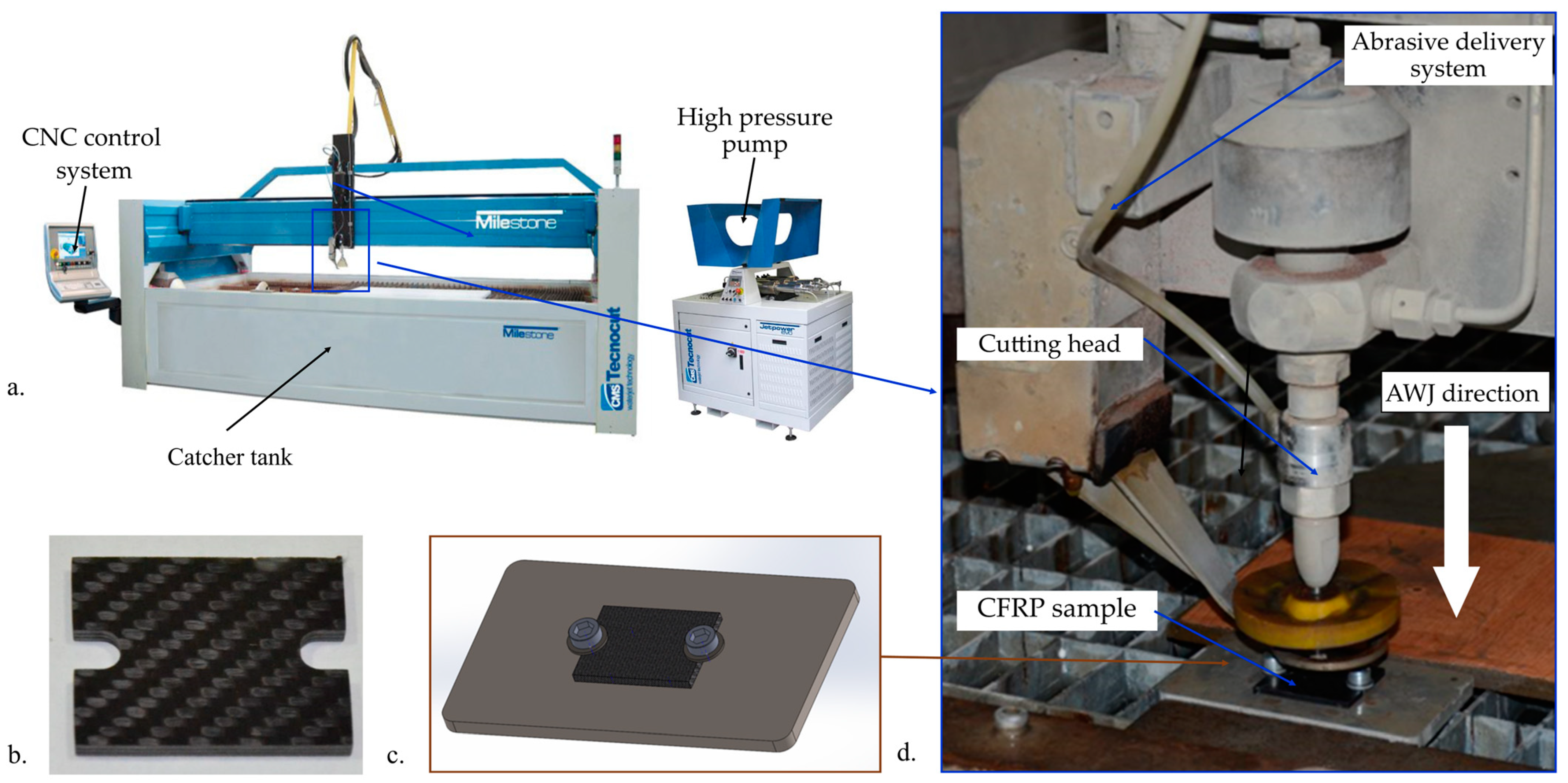
2.3. Experimental Procedure and Results

The experimental study employed an industrial AWJ machine, the Tecnocut Milestone 1740 model, as illustrated in Figure 2a. The Tecnocut Milestone 1740 is a state-of-the-art high-precision AWJ machine engineered for industrial applications. It has a robust high-pressure pump capable of delivering up to 4150 bar (60,000 psi) of water pressure. It can cut through an extensive range of materials with remarkable efficiency. The machine has a cutting area of 4000 mm × 1700 mm × 250 mm. It also has good accuracy (±0.01 mm) and repeatability [51].
Figure 2 illustrates the experiment setup. Table 2 presents the experimental parameters used in this study. The CFRP specimens were cut using AWJ at dimensions of 60 mm × 60 mm (Figure 2b) and clamped using screws in a custom clamping system (Figure 2c).
The PG 2000 Cutting Tool Inspection System produced by Guhring was the optical microscope employed for investigating the holes made by AWJ piercing. The PG 2000 offers high-precision measurement capabilities, with a resolution of up to 0.1 μm and an accuracy of ±1 micrometer. Its high-quality lenses are ideal for capturing images of workpiece edges, with magnification settings ranging from 10× to 2000×.
CFRP samples were cut with AWJ into two pieces, and the delamination extent (Dext) was measured on the cross-section. The Dext was calculated using the following formula:
Dext = (Ddel − Dhole)/2
where Ddel is the maximum diameter of the delamination area and Dhole is the pierce hole diameter. Table 3 presents the experimental results.

2.4. Artificial Neural Network (ANN) Model

The present study proposes the use of a vanilla artificial neural network (ANN) to identify the optimal combination of process parameters that would prevent the delamination of composite materials during AWJ piercing. In this study, the network was trained using the backpropagation method using MATLAB’s neural network toolbox (MATLAB R2024a). Backpropagation is a supervised learning technique used for training artificial neural networks (ANNs). It involves a two-phase cycle: forward propagation of input data to generate output and backward propagation of error to adjust weights and biases in the network.
The network architecture consists of a hidden layer and an output layer. The sigmoid activation function was used in the hidden layer. This configuration captures the non-linear relationships and provides linear predictions suitable for regression tasks.
The network architecture is composed of an input layer, which consists of neurons representing the process parameters; a hidden layer, which contains 10 neurons with a sigmoid activation function; and an output layer, which comprises neurons with linear activation functions to predict the extent of delamination.
Initially, the data were imported from an Excel file where the training data were stored. The data were then divided into distinct subsets for training (70%), validation (15%), and testing (15%). A neural network was defined (Figure 3) and trained for a number of epochs until the change in error was very small. The performance of the trained network was then evaluated through metrics such as mean squared error and regression analysis. Finally, the results were analyzed using visualization techniques, including regression fit plots and error histograms.
The main steps of modeling the process for AWJ piercing optimization are:
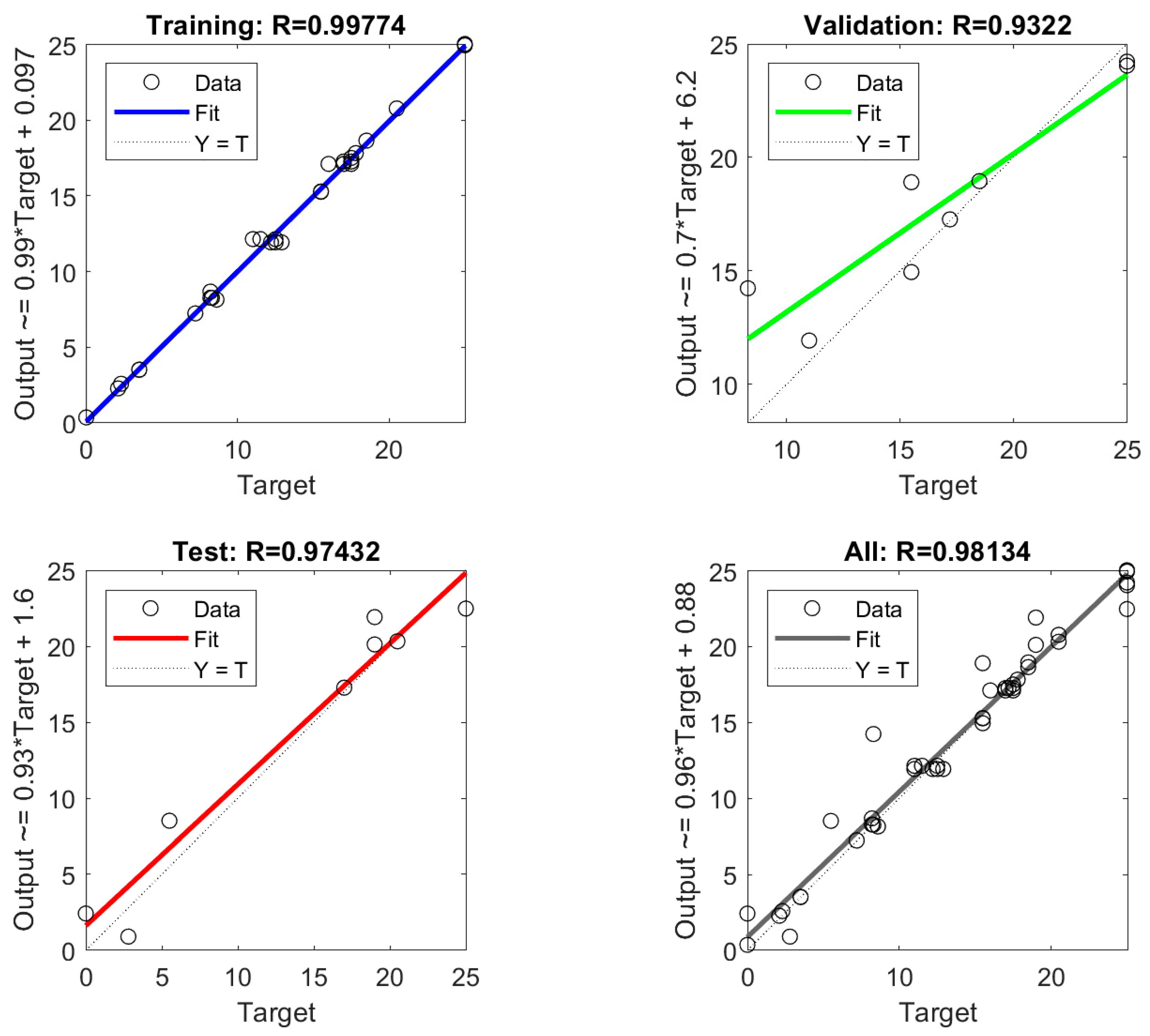
  • Data input. The first step in the modeling process involves feeding the process parameters into the neural network. The dataset consists of predictors (input data) and responses (target data). A double array with 51 samples and 4 features representing the process parameters (water jet pressure P, standoff distance SOD, material thickness t, and abrasive start synchronization ASS) comprises the predictors. The response consists of a double array with 51 samples and 4 features representing the delamination extent (Dext). Each feature in the predictor array is represented as a neuron in the input layer of the network, which serves as the starting point for data processing. The data input (51 samples) was split, with 70% used for ANN model training, 15% for model validation, and 15% for model testing.
  • Hidden layer processing. After the input data enter the network, they are processed by the hidden layer, which contains 10 neurons. These neurons use a sigmoid activation function to introduce non-linearity into the model. Each hidden neuron calculates a weighted sum of the input values, adding a bias term to this sum. The sigmoid function is then applied to this weighted sum, which helps the network learn complex patterns and relationships between the input parameters and the desired output.
  • Output layer processing. The processed data from the hidden layer are then passed to the output layer. The neurons in the output layer use a linear activation function suitable for producing continuous output values. Each output neuron calculates a weighted sum of the outputs from the hidden layer neurons, including a bias term. The linear function is then applied to this weighted sum to produce the final output, which in this case is a prediction of delamination.
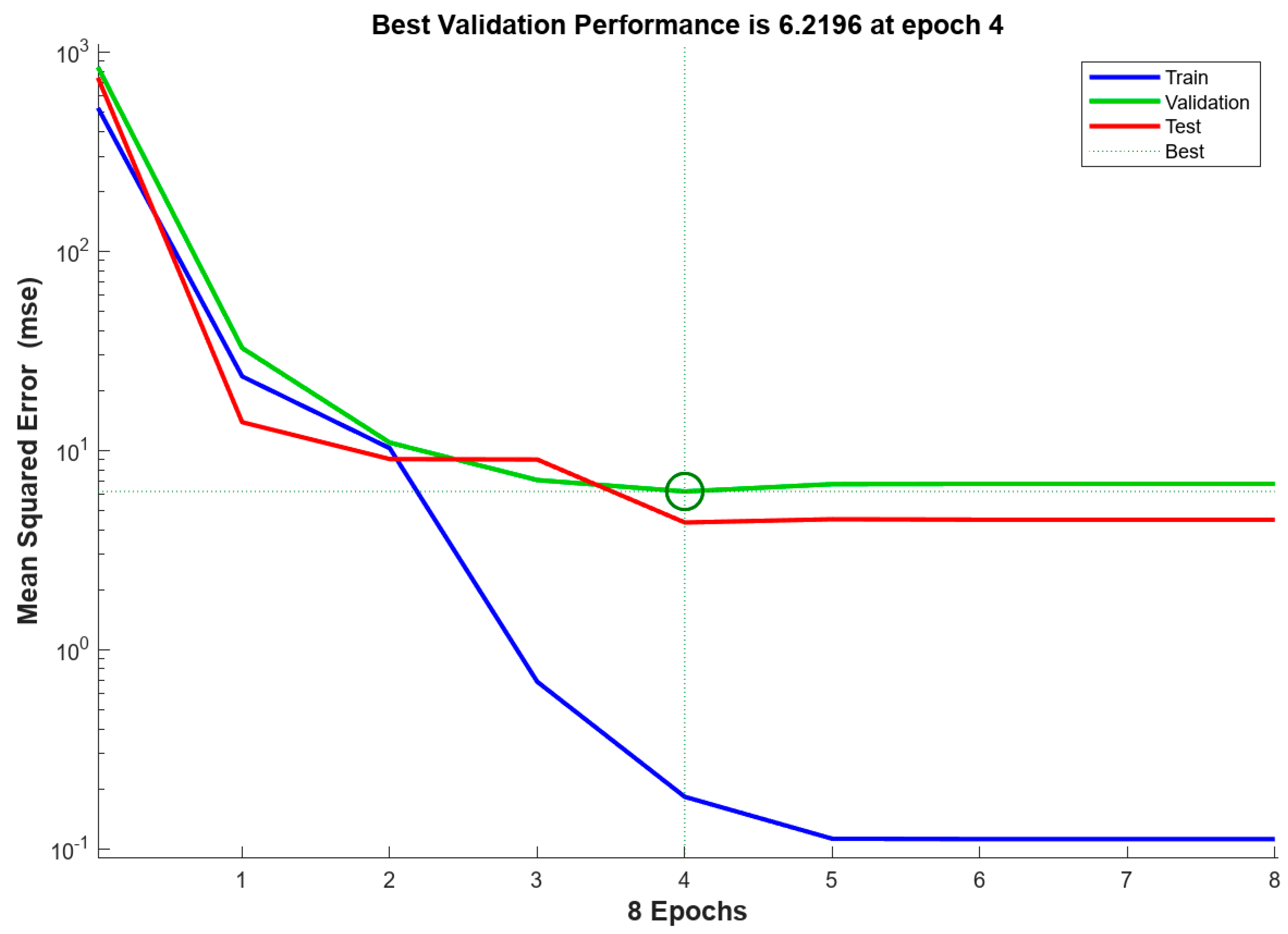
  • Loss calculation. The network’s predicted output is compared with the actual measurements of delamination. The difference between these values is quantified using the mean squared error (MSE) loss function, which measures how well the network’s predictions match the real data. This loss value indicates the network’s performance and guides further adjustments.
  • Backward propagation. To improve the network’s performance, backpropagation is used; this calculates how much each weight and bias contributes to the total error. The error at the output layer is determined by comparing the predicted and actual values. It is then used to calculate the error for each neuron in the hidden layer, considering how the output of each hidden neuron influences the final prediction.
  • Parameter update. Using the errors calculated during backpropagation, the network updates its weights and biases to reduce the loss. This is accomplished using a technique called gradient descent, which adjusts each parameter slightly in the direction that will decrease the error. The learning rate determines the size of these adjustments. In this study, the Levenberg–Marquardt algorithm is used for training, which is known for its efficiency in handling non-linear least squares problems.
  • Iteration. The entire process of forward propagation, loss calculation, backward propagation, and parameter update is repeated for many iterations, known as epochs. This iterative process continues until the network’s performance stabilizes and the loss converges to a minimum value, indicating that the network has been effectively trained.
The MATLAB program developed for ANN modeling of AWJ piercing is presented in Appendix A.

3. Results and Discussions

3.1. Performance of the ANN Model in Predicting Delamination

To investigate the neural network performance, the mean squared error (MSE) was involved. The performance plot graph (Figure 4) represents the MSE of the neural network during the training, validation, and testing phases.
The point at which the validation MSE is at its lowest is considered the best validation performance, marked by the green circle on the plot. In this case, the best validation performance is 6.2196 at epoch 4.
The decreasing trend of the training and validation MSE indicates effective learning. The training MSE continues to decrease significantly, suggesting that the model fits the training data well.
The validation MSE stabilizes after epoch 4, indicating that further training does not significantly improve the model’s performance on validation data and helps in identifying the optimal stopping point to avoid overfitting.
The test MSE aligns closely with the validation MSE, indicating that the model generalizes well to new, unseen data and that the training process is effective.
The set of plots shown in Figure 5 illustrates the regression analysis of the neural network’s performance across different phases: training, validation, testing, and overall. Each plot compares the network’s predicted outputs to the actual target values and provides the correlation coefficient (R), which indicates how well the predicted outputs match the actual targets.
All R-values are close to 1, which translates into a strong linear relationship between the predicted outputs and the actual targets. The neural network model captures the underlying patterns in the data. The high R-values in the training (0.99774), validation (0.9322), and testing (0.97432) phases also suggest that the model performs consistently well. This minimizes overfitting and maintains generalization to new data. The fit lines also indicate that the model has a good performance.

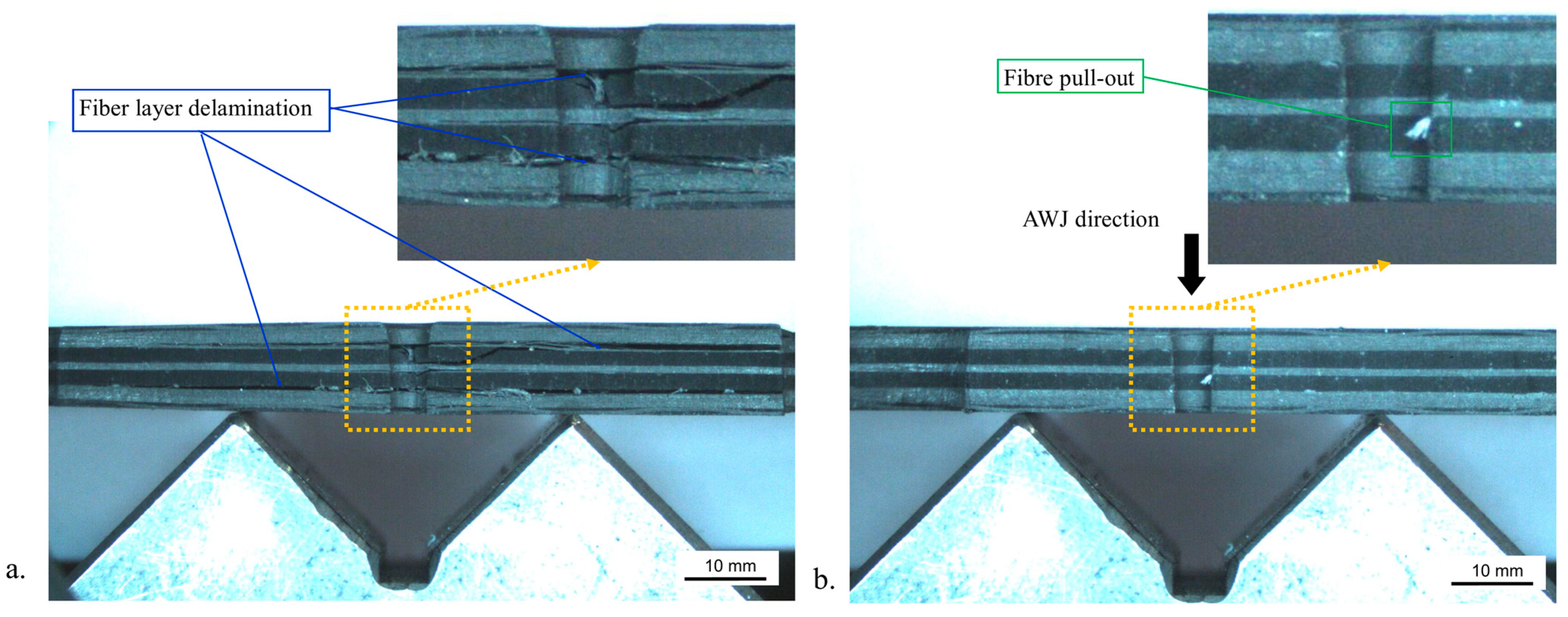
3.2. The Morphology of the Machined Surfaces Investigation

The machined surfaces were examined under a microscope to study the behavior of CFRP during the piercing process, focusing on aspects such as delamination, uncut fibers, and abrasive particle embedment.
The microscope images of the specimen shown in Figure 6a highlight the general form of composite material delamination. This specimen was machined during experimental run number 3 using 250 MPa water pressure, a 5.5 mm stand-off distance, and a 5 mm material thickness, without abrasive start synchronization. The observed delamination extend (Dext) was 17.5 mm wide. The delamination appeared throughout the entire thickness of the composite material, not just as a single crack.
Figure 6b shows the morphology of a hole created by AWJ piercing without delamination. It was machined during experimental run number 38 using 100 MPa water pressure, a 5.5 mm stand-off distance, and a 5 mm material thickness, and the abrasive start was synchronized with the water start. The hole’s dimensions were determined by measuring the hole dimensions at the top (Ø1.2 mm) and at the bottom (Ø1.1 mm). The fillet radius in the bottom area was 0.18 mm. Carbon fiber pull-out was also observed on a few of the machined surfaces.

3.3. ANN Model Validation

The new ANN model developed was validated in an experimental study and by manufacturing a CFRP part in an industrial application. To validate the model, the Simulink platform 2023 was used. In Figure 7, the Simulink diagram designed for this test is shown. The input block (the constant block—x1) was configured using the validation input data. The neural network block was then loaded with the trained network parameters. The output block (y1) was set up to capture the model’s predictions.
After executing the simulation in Simulink, the predicted outputs for the validation inputs were generated. These outputs were then compared with actual measurements from the validation dataset. The AWJ equipment used in this validation was the same industrial equipment used in the primary experiments, the Tecnocut Milestone 1740 machine.
The ANN model’s predictions were compared with the values obtained during the experimental tests. Table 4 presents the process parameters used and the experimental results.
A paired-sample t-test was conducted to compare the predicted values and the measured test values. There was no significant difference in the scores for the predicted values (M = 12.56, SD = 9.77) and measured values (M = 12.08, SD = 9.82); (t (9) = 0.496), (p = 0.632). A two-tailed test was used with a significance level of α = 0.05. This confirmed the reliability of the ANN in predicting delamination extent values.
The proposed model was applied to identify optimal process parameters for machining 50 CFRP industrial parts with a thickness of 6 mm with AWJ. Both the external contours and two slots were machined with AWJ, as illustrated in Figure 8a.
In the first setup, the process parameter selection was made on the basis of the recommendations provided by the manufacturer of the AWJ Tecnocut equipment for piercing general brittle material. The process parameters for AWJ piercing were P = 150 MPa (low pressure for piercing), SOD = 1 mm, ma = 0.45 kg/min, t = 6 mm, and abrasive start synchronization OFF; for AWJ cutting, the process parameters were P = 350 MPa (high pressure for cutting) and V = 300 mm/min. The part was processed in 1.8 min, resulting in significant fiber layer delamination, as shown in Figure 8b.
On the basis of the optimization made with the new ANN model, the following process parameters were used for piercing: P = 100 MPa, ma = 0.45 kg/min, SOD = 0.5 mm, and abrasive start synchronization ON. These parameters resulted in a predicted delamination extent (Dext) of 0 mm. For cutting, the parameters were P = 350 MPa, ma = 0.45 kg/min, SOD = 0.5 mm, and V = 300 mm/min. Figure 8c shows the part produced with the proposed piercing method. This part was processed in the same machining time with no delamination and met the required quality characteristics.
The optimized parameters ensure AWJ piercing without delamination, validating the ANN model’s industrial applicability.

4. Conclusions

In this study, an artificial neural network model was used to identify the optimal combination of process parameters for eliminating delamination in composite materials during AWJ piercing. The model was trained using backpropagation with MATLAB’s neural network toolbox and validated through both experimental studies and industrial applications.
The developed ANN model accurately predicts the delamination extent (Dext) during AWJ piercing. The high correlation between predicted and actual values (training R = 0.97843, validation R = 0.97572, testing R = 0.96891) shows the model’s reliability and effectiveness in optimizing process parameters. The validation tests showed that there are no statistically significant differences between test results and predictions, qualifying the model as a reliable basis for process optimization.
The ANN model can help in identifying optimal process parameters (water pressure, standoff distance, and abrasive start synchronization) and ensure piercing without delamination. This optimization helps to maintain the structural integrity and performance of CFRP components in industrial applications.
The Simulink platform was effectively utilized to validate the ANN model. The validation process included configuring input and output blocks and ensuring the neural network block was loaded with trained parameters. This platform can be easily used for developing real-time monitoring and control systems for industrial implementation.
The ANN model was successfully applied to the machining of 50 CFRP industrial parts without delamination. This real-world application confirmed the model’s robustness and practical utility.
Future research should focus on incorporating additional process parameters, such as abrasive characteristics, cutting head dimensions, and material characteristics, to enhance the ANN model’s generalizability. Also, with a larger dataset, the ANN should be able to identify more intricate patterns in the data and make better predictions. Additionally, integrating the model into the AWJ equipment control software could help determine the optimal combination of process parameters.
The authors of the current study acknowledge some limitations of the current study. Firstly, the number of experiments used to train the model was quite low compared with regular datasets used with ANNs. The collection of data was constrained by time and material limitations. Nevertheless, other studies [49,52,53,54] have successfully trained neural networks using a limited sample. The focus of this study was more data-centric and was aimed at obtaining high-quality data and the correct data using DoE. Also, a vanilla neural network was used instead of a custom-built architecture. As this was an exploratory study, the authors considered it appropriate to test a basic model and adapt it in future studies depending on the results obtained herein.
Artificial intelligence can be successfully applied to optimize AWJ machining processes. This research demonstrates the potential of AI-driven solutions to improve the quality and efficiency of CFRP machining, opening new directions for broader applications and continuous improvement in the field.

Author Contributions

Conceptualization, methodology, investigation, I.A.P., V.I.B., S.S. and A.I.P.; validation, I.A.P. and A.I.P.; software, I.A.P. and V.I.B.; writing-original draft, I.A.P., V.I.B. and A.I.P.; writing—review and editing, S.S., N.B. and N.P.; research funding, N.B. All authors have read and agreed to the published version of the manuscript.

Funding

This research was supported by the HORIZON 2020–DiCoMI Project “Directional Composites through Manufacturing Innovation”, GA Nr. 778068.

Institutional Review Board Statement

Not applicable.

Informed Consent Statement

Not applicable.

Data Availability Statement

The original contributions presented in the study are included in the article, further inquiries can be directed to the corresponding author.

Conflicts of Interest

The authors declare no conflicts of interest.

Appendix A

The MATLAB program developed for the ANN modeling of AWJ piercing:
  • function [y1] = myNeuralNetworkFunction(x1)
  • %MYNEURALNETWORKFUNCTION neural network simulation function.
  • % Auto-generated by MATLAB, 23-Jul-2024 13:01:05.
  • % [y1] = myNeuralNetworkFunction(x1) takes these arguments:
  • % x = Qx4 matrix, input #1
  • % and returns:
  • % y = Qx1 matrix, output #1
  • % where Q is the number of samples.
  • %#ok<*RPMT0>
  • % ===== NEURAL NETWORK CONSTANTS =====
  • % Input 1
  • x1_step1.xoffset = [100;1;0;2];
  • x1_step1.gain = [0.00666666666666667;0.222222222222222;2;0.666666666666667];
  • x1_step1.ymin = −1;
  • % Layer 1
  • b1 = [3.0942814848929001137;−1.6412631940412265585;−1.7357019482919628928;0.0046341803092739136671;−0.12092182611574373019;0.0017721478219405242815;−0.73329001720699682476;0.89508232533568099498;1.871406632027108774;−2.2806622933958196064];
  • IW1_1 = [−1.3180624629005928128 −1.3806326862996611826 0.80956172730409159399 0.24635899622397591791;1.1998835046210121202 −0.76280403929718321177 1.9324656114513456551 0.80216733375313908905;0.40939565241548864227 −2.3991523673818146989 −0.97839919126131558169 −0.29980263631366899091;3.0237925270406353917 −0.1146067506786898893 0.38968148073836933465 −0.25453631251896452481;0.85283782903481264448 −0.47911720974742144641 −1.2273801839673017522 2.1822395897464237358;−0.44452333762914120197 0.046225899173519845176 0.31531716693307315635 −2.6451698302159476484;−2.082201349833978643 −0.76346898345159097676 0.80987596832556574267 −0.26354987734844792513;0.23328632180445929567 1.9398593712767222552 −2.1170295819115390046 −0.95572595759438017105;1.2950325142995149363 −0.40655955776770902332 −1.3348898800375803564 1.9412701409376558193;0.2620678477346494728 1.4222211061809311161 −1.0819256332215649863 −1.8734496430651590426];
  • % Layer 2
  • b2 = 0.037914970571524556076;
  • LW2_1 = [−0.3338122113448129813 −0.062787018149683293533 −0.023067778401084607087 0.30886252071691638887 0.11947332736834551103 0.25517375503750572285 −0.46461748677279546271 0.073666775477091439583 0.15553036075489234946 −0.23597420977667460384];
  • % Output 1
  • y1_step1.ymin = −1;
  • y1_step1.gain = 0.08;
  • y1_step1.xoffset = 0;
  • % ===== SIMULATION ========
  • % Dimensions
  • Q = size(x1,1); % samples
  • % Input 1
  • x1 = x1’;
  • xp1 = mapminmax_apply(x1,x1_step1);
  • % Layer 1
  • a1 = tansig_apply(repmat(b1,1,Q) + IW1_1*xp1);
  • % Layer 2
  • a2 = repmat(b2,1,Q) + LW2_1*a1;
  • % Output 1
  • y1 = mapminmax_reverse(a2,y1_step1);
  • y1 = y1’;
  • end
  • % ===== MODULE FUNCTIONS ========
  • % Map Minimum and Maximum Input Processing Function
  • function y = mapminmax_apply(x,settings)
  • y = bsxfun(@minus,x,settings.xoffset);
  • y = bsxfun(@times,y,settings.gain);
  • y = bsxfun(@plus,y,settings.ymin);
  • end
  • % Sigmoid Symmetric Transfer Function
  • function a = tansig_apply(n,~)
  • a = 2 ./(1 + exp(−2*n)) − 1;
  • end
  • % Map Minimum and Maximum Output Reverse-Processing Function
  • function x = mapminmax_reverse(y,settings)
  • x = bsxfun(@minus,y,settings.ymin);
  • x = bsxfun(@rdivide,x,settings.gain);
  • x = bsxfun(@plus,x,settings.xoffset);
  • end

References

  1. Geier, N.; Xu, J.; Poór, D.I.; Dege, J.H.; Davim, J.P. A review on advanced cutting tools and technologies for edge trimming of carbon fibre reinforced polymer (CFRP) composites. Compos. Part B Eng. 2023, 266, 111037. [Google Scholar] [CrossRef]
  2. Aamir, M.; Tolouei-Rad, M.; Giasin, K.; Nosrati, A. Recent advances in drilling of carbon fiber–reinforced polymers for aerospace applications: A review. Int. J. Adv. Manuf. Technol. 2019, 105, 2289–2308. [Google Scholar] [CrossRef]
  3. Miron, A.; Balc, N.; Popan, A.; Cristina, B.; Paul, B. Studies on Water Jet Cutting of 2D Parts Made from Carbon Fiber Composite Materials. Acad. J. Manuf. Eng. 2013, 11, 87. [Google Scholar]
  4. Bere, P.; Popescu, A.; Dudescu, C.; Hancu, L. Influence of the stacking sequence on the mechanical proprieties of glass fiber reinforced polymer. MATEC Web Conf. 2017, 112, 04006. [Google Scholar] [CrossRef]
  5. Vasile Adrian, C.; Paul, B.; Marian, B.; Sorin, G.; Cristina, B. Development of Environmental Technology for Carbon Fibre Reinforced Materials Recycling. Mater. Plast. 2013, 50, 79–83. [Google Scholar]
  6. Birleanu, C.; Pustan, M.; Pop, G.; Cioaza, M.; Popa, F.; Lazarescu, L.; Contiu, G. Experimental Investigation of the Tribological Behaviors of Carbon Fiber Reinforced Polymer Composites under Boundary Lubrication. Polymers 2022, 14, 3716. [Google Scholar] [CrossRef]
  7. Ding, J.; Cheng, L.; Chen, X.; Chen, C.; Liu, K. A review on ultra-high cycle fatigue of CFRP. Compos. Struct. 2021, 256, 113058. [Google Scholar] [CrossRef]
  8. Bere, P.; Neamtu, C.; Udroiu, R. Novel Method for the Manufacture of Complex CFRP Parts Using FDM-based Molds. Polymers 2020, 12, 2220. [Google Scholar] [CrossRef] [PubMed]
  9. Golewski, P.; Sadowski, T.; Kneć, M.; Budka, M. The effect of thermal aging degradation of CFRP composite on its mechanical properties using destructive and non-destructive methods and the DIC system. Polym. Test. 2023, 118, 107902. [Google Scholar] [CrossRef]
  10. Qin, G.; Zheng, L.; Mi, P.; Zhu, Y.; Li, M.; Na, J.; Wang, Y. Influence of single or multi-factor coupling of temperature, humidity and load on the aging failure of adhesively bonded CFRP / aluminum alloy composite joints for automobile applications. Int. J. Adhes. Adhes. 2023, 123, 103345. [Google Scholar] [CrossRef]
  11. Mohamed, H. Trimming of CFRP aircraft components. In Proceedings of the WJTA-IMCA Conference and Expo, Houston, TX, USA, 9–11 September 2013. [Google Scholar]
  12. Popan, I.A.; Bocanet, V.; Balc, N.; Popan, A.I. Investigation on Feed Rate Influence on Surface Quality in Abrasive Water Jet Cutting of Composite Materials, Monitoring Acoustic Emissions. In Advances in Manufacturing Engineering and Materials; Hloch, S., Klichová, D., Krolczyk, G.M., Chattopadhyaya, S., Ruppenthalová, L., Eds.; Springer International Publishing: Cham, Switzerland, 2019; pp. 105–113. ISBN 978-3-319-99352-2. [Google Scholar]
  13. Sabău, E.; Udroiu, R.; Bere, P.; Buranský, I.; Miron-Borzan, C.-Ş. A Novel Polymer Concrete Composite with GFRP Waste: Applications, Morphology, and Porosity Characterization. Appl. Sci. 2020, 10, 2060. [Google Scholar] [CrossRef]
  14. Shanmugam, D.K.; Nguyen, T.; Wang, J. A study of delamination on graphite/epoxy composites in abrasive waterjet machining. Compos. Part A Appl. Sci. Manuf. 2008, 39, 923–929. [Google Scholar] [CrossRef]
  15. Popan, I.A.; Cosma, C.; Popan, A.I.; Bocăneț, V.I.; Bâlc, N. Monitoring Equipment Malfunctions in Composite Material Machining: Acoustic Emission-Based Approach for Abrasive Waterjet Cutting. Appl. Sci. 2024, 14, 4901. [Google Scholar] [CrossRef]
  16. Hloch, S.; Svobodová, J.; Srivastava, A.K.; Srivastava, M.; Poloprudský, J.; Nag, A. Submerged pulsating water jet erosion of ductile material. Wear 2024, 538–539, 205243. [Google Scholar] [CrossRef]
  17. Popan, I.A.; Balc, N.; Popan, A.I. Avoiding carbon fibre reinforced polymer delamination during abrasive water jet piercing: A new piercing method. Int. J. Adv. Manuf. Technol. 2022, 119, 1139–1152. [Google Scholar] [CrossRef]
  18. Stolárik, G.; Klichová, D.; Poloprudský, J.; Chlupová, A.; Nag, A.; Hloch, S. Submerged surface texturing of AISI 304L using the pulsating water jet method. Arch. Civ. Mech. Eng. 2024, 24, 207. [Google Scholar] [CrossRef]
  19. Popan, A.; Cosma, C.; Popan, A.I.; Trif, A.; Nicolae, P. Abrasive Water Jet Piercing Simulation of Carbon Fibre Reinforced Polymer. Acta Tech. Napoc. Ser. Appl. Math. Mech. Eng. 2023, II, 209–214. [Google Scholar]
  20. Kong, M.C.; Anwar, S.; Billingham, J.; Axinte, D.A. Mathematical modelling of abrasive waterjet footprints for arbitrarily moving jets: Part I—Single straight paths. Int. J. Mach. Tools Manuf. 2012, 53, 58–68. [Google Scholar] [CrossRef]
  21. Basarman, A.-P.; Lobonțiu, M. Kerf variation analysing for abrasive water jet cutting of a steel square part. MATEC Web Conf. 2017, 112, 03002. [Google Scholar] [CrossRef]
  22. Filip, A.C.; Mihail, L.A.; Vasiloni, M.A. An experimental study on the dimensional accuracy of holes made by abrasive waterjet machining of Hardox steels. MATEC Web Conf. 2017, 137, 02003. [Google Scholar] [CrossRef]
  23. Ozcan, Y.; Tunc, L.T.; Kopacka, J.; Cetin, B.; Sulitka, M. Modelling and simulation of controlled depth abrasive water jet machining (AWJM) for roughing passes of free-form surfaces. Int. J. Adv. Manuf. Technol. 2021, 114, 3581–3596. [Google Scholar] [CrossRef]
  24. Chen, M.; Zhang, S.; Zeng, J.; Chen, B. Correcting shape error located in cut-in/cut-out region in abrasive water jet cutting process. Int. J. Adv. Manuf. Technol. 2019, 102, 1165–1178. [Google Scholar] [CrossRef]
  25. Zou, X.; Fu, L.; Wu, L.; Zuo, W. Research on Multiphase Flow and Nozzle Wear in a High-Pressure Abrasive Water Jet Cutting Head. Machines 2023, 11, 614. [Google Scholar] [CrossRef]
  26. Bañon, F.; Sambruno, A.; Batista, M.; Simonet, B.; Salguero, J. Study of the surface quality of carbon fiber–reinforced thermoplastic matrix composite (CFRTP) machined by abrasive water jet (AWJM). Int. J. Adv. Manuf. Technol. 2020, 107, 3299–3313. [Google Scholar] [CrossRef]
  27. Perec, A. Experimental research into alternative abrasive material for the abrasive water-jet cutting of titanium. Int. J. Adv. Manuf. Technol. 2018, 97, 1529–1540. [Google Scholar] [CrossRef]
  28. Alexandru, P.I. Modeling and Optimization of the Abrasive Water Jet Cutting Process. In Modeling and Optimization in Manufacturing, 1st ed.; Pruncu, C.I., Jiang, J., Eds.; Wiley: Hoboken, NJ, USA, 2021; pp. 113–131. ISBN 978-3-527-34694-3. [Google Scholar]
  29. Nasulea, D.; Filip, A.C.; Zisu, S.; Oancea, G. Research Regarding the Dimensional Precision of Electrical Steel Strips Machined by Waterjet Cutting in Multilayer Packages. Processes 2023, 11, 2788. [Google Scholar] [CrossRef]
  30. Natarajan, Y.; Murugesan, P.K.; Mohan, M.; Liyakath Ali Khan, S.A. Abrasive Water Jet Machining process: A state of art of review. J. Manuf. Process. 2020, 49, 271–322. [Google Scholar] [CrossRef]
  31. Dhanawade, A.; Kumar, S. Experimental study of delamination and kerf geometry of carbon epoxy composite machined by abrasive water jet. J. Compos. Mater. 2017, 51, 3373–3390. [Google Scholar] [CrossRef]
  32. Kim, G.; Denos, B.R.; Sterkenburg, R. Influence of different piercing methods of abrasive waterjet on delamination of fiber reinforced composite laminate. Compos. Struct. 2020, 240, 112065. [Google Scholar] [CrossRef]
  33. Hlaváč, L.M. Revised Model of Abrasive Water Jet Cutting for Industrial Use. Materials 2021, 14, 4032. [Google Scholar] [CrossRef] [PubMed]
  34. Caggiano, A.; Nele, L. Artificial Neural Networks for Tool Wear Prediction Based on Sensor Fusion Monitoring of CFRP/CFRP Stack Drilling. IJAT 2018, 12, 275–281. [Google Scholar] [CrossRef]
  35. Rakic, S.; Softic, S.; Vilkas, M.; Lalic, B.; Marjanovic, U. Key Indicators for Student Performance at the E-Learning Platform: An SNA Approach. In Proceedings of the 2018 16th International Conference on Emerging eLearning Technologies and Applications (ICETA), Stary Smokovec, Slovakia, 15–16 November 2018; IEEE: Piscataway, NJ, USA, 2018; pp. 463–468. [Google Scholar]
  36. Mitić, J.; Vitković, N.; Trajanović, M.; Górski, F.; Păcurar, A.; Borzan, C.; Sabău, E.; Păcurar, R. Utilizing Artificial Neural Networks for Geometric Bone Model Reconstruction in Mandibular Prognathism Patients. Mathematics 2024, 12, 1577. [Google Scholar] [CrossRef]
  37. Grozav, S.D.; Sterca, A.D.; Kočiško, M.; Pollák, M.; Ceclan, V. Feasibility of Predictive Models for the Quality of Additive Manufactured Components Based on Artificial Neural Networks. Machines 2022, 10, 128. [Google Scholar] [CrossRef]
  38. Ficko, M.; Begic-Hajdarevic, D.; Cohodar Husic, M.; Berus, L.; Cekic, A.; Klancnik, S. Prediction of Surface Roughness of an Abrasive Water Jet Cut Using an Artificial Neural Network. Materials 2021, 14, 3108. [Google Scholar] [CrossRef]
  39. Aydin, G.; Karakurt, I.; Hamzacebi, C. Artificial neural network and regression models for performance prediction of abrasive waterjet in rock cutting. Int. J. Adv. Manuf. Technol. 2014, 75, 1321–1330. [Google Scholar] [CrossRef]
  40. Teti, R.; Mourtzis, D.; D’Addona, D.M.; Caggiano, A. Process monitoring of machining. CIRP Ann. 2022, 71, 529–552. [Google Scholar] [CrossRef]
  41. Bilal, D.K.; Unel, M.; Tunc, L.T. Improving Vision Based Pose Estimation Using LSTM Neural Networks. In Proceedings of the IECON 2020 The 46th Annual Conference of the IEEE Industrial Electronics Society, Singapore, 18–21 October 2020; IEEE: Piscataway, NJ, USA, 2020; pp. 483–488. [Google Scholar]
  42. Basulo Ribeiro, J.; Amorim, M. How To Accelerate Digital Transformation in Companies With Lean Philosophy? Contributions Based on a Practical Case. Int. J. Ind. Eng. Manag. 2023, 14, 94–104. [Google Scholar] [CrossRef]
  43. Cardoso, M.; Ares, E.; Ferreira, L.P.; Pelaez, G. Using Index Function and Artificial Intelligence to assess Sustainability: A Bibliometric analysis. Int. J. Ind. Eng. Manag. 2023, 14, 311–325. [Google Scholar] [CrossRef]
  44. Mattera, G.; Polden, J.; Caggiano, A.; Nele, L.; Pan, Z.; Norrish, J. Semi-supervised learning for real-time anomaly detection in pulsed transfer wire arc additive manufacturing. J. Manuf. Process. 2024, 128, 84–97. [Google Scholar] [CrossRef]
  45. Zain, A.M.; Haron, H.; Sharif, S. Estimation of the minimum machining performance in the abrasive waterjet machining using integrated ANN-SA. Expert Syst. Appl. 2011, 38, 8316–8326. [Google Scholar] [CrossRef]
  46. Grozav, S.D.; Sterca, A.D.; Kočiško, M.; Pollák, M.; Ceclan, V. Artificial Neural Network-Based Predictive Model for Finite Element Analysis of Additive-Manufactured Components. Machines 2023, 11, 547. [Google Scholar] [CrossRef]
  47. Biruk-Urban, K.; Zagórski, I.; Kulisz, M.; Leleń, M. Analysis of Vibration, Deflection Angle and Surface Roughness in Water-Jet Cutting of AZ91D Magnesium Alloy and Simulation of Selected Surface Roughness Parameters Using ANN. Materials 2023, 16, 3384. [Google Scholar] [CrossRef] [PubMed]
  48. Prabhu, R.; Kanthababu, M. Prediction of surface roughness and depth of cut in abrasive waterjet milling of alumina ceramic using Machine learning algorithms. Expert Syst. Appl. 2024, 246, 123168. [Google Scholar] [CrossRef]
  49. Gupta, T.V.K.; Ramkumar, J.; Tandon, P.; Vyas, N.S. Application of Artificial Neural Networks in Abrasive Water Jet Milling. Procedia CIRP 2015, 37, 225–229. [Google Scholar] [CrossRef]
  50. ECOTECH—CFRP Manufacturer. 2024. Available online: https://www.r-g.de (accessed on 1 July 2024).
  51. Tecnocut Milestone 1740—Equipment Specifications. 2024. Available online: www.scmgroup.com (accessed on 1 July 2024).
  52. Kayabasi, E.; Ozturk, S.; Celik, E.; Kurt, H. Determination of cutting parameters for silicon wafer with a Diamond Wire Saw using an artificial neural network. Sol. Energy 2017, 149, 285–293. [Google Scholar] [CrossRef]
  53. Djurović, S.; Lazarević, D.; Ćirković, B.; Mišić, M.; Ivković, M.; Stojčetović, B.; Petković, M.; Ašonja, A. Modeling and Prediction of Surface Roughness in Hybrid Manufacturing–Milling after FDM Using Artificial Neural Networks. Appl. Sci. 2024, 14, 5980. [Google Scholar] [CrossRef]
  54. Bedelean, B.; Ispas, M.; Răcășan, S. Applying the Artificial Neural Network and Response Surface Methodology to Optimize the Drilling Process of Plywood. Appl. Sci. 2023, 13, 11343. [Google Scholar] [CrossRef]
Figure 1. The AWJ process applied for CFRP machining: (a) The AWJ process; (b) the CFRP delamination mechanism.
Applsci 14 08512 g001
Figure 2. The experiment setup: (a) the Tecnocut Milestone 1740 AWJ equipment, (b) the CFRP workpiece, (c) the clamping system, and (d) the cutting head.
Applsci 14 08512 g002
Figure 3. The neural network presentation.
Applsci 14 08512 g003
Figure 4. The neural network performance graph.
Applsci 14 08512 g004
Figure 5. The regression analysis of the neural network’s performance.
Applsci 14 08512 g005
Figure 6. The morphology of the machined surfaces: (a) the delaminated specimen and (b) the specimen with free delamination.
Applsci 14 08512 g006
Figure 7. The Simulink diagram for ANN validation.
Applsci 14 08512 g007
Figure 8. The CFRP cut for the validation of the proposed method.
Applsci 14 08512 g008
Table 1. Experimental parameters.
ParametersValue
Water jet pressure (P)100, 143.93, 250, 356.07, 400 MPa
Standoff distance (SOD)1, 2.32, 5.5, 8.68, 10 mm
Material thickness (t)2, 5 mm
Abrasive start synchronization (ASS)On/Off
Abrasive mass flow (ma)0.45 kg/min
Abrasive size80 mesh
Focusing tube diameter0.76 mm
Orifice diameter0.35 mm
Table 2. Cutting head characteristics.
ParametersValue
Cutting headCarat 3.0 Gardella
Abrasive inlet angleΨ = 40 deg.
OrificeDiamond, do = 0.35 mm
Focusing tubeCeratizit WJNS (df = 0.76 mm/lf = 101.6 mm)
Table 3. Experimental results.
RunPSODASStDextRunPSODASStDext
MPammOn/Offmmmm MPammOn/Offmmmm
12505.5Off217.526356.072.32Off225
22505.5On212.5272505.5On212.5
32505.5Off517.52825010Off517.8
4143.932.32Off58.6292505.5Off216.1
52501Off515.5302505.5On511.2
6143.938.68Off58.331356.078.68On520.5
7356.078.68Off52532356.078.68On220.5
81005.5On203325010On215.5
92501On58.234356.078.68Off225.2
10356.072.32Off525351005.5Off55.5
112505.5Off217.536143.932.32On52.8
122505.5Off217.5372505.5On512.5
13356.072.32On218.5381005.5On50
14143.938.68On52.33925010On515.5
154005.5Off525402505.5On211
162505.5Off517.5414005.5On519
172501On28.2422505.5On512.5
18143.932.32On22.1432505.5Off517.1
192505.5Off517.2442505.5On211.5
202501Off215.5452505.5Off517.1
2125010Off217.5462505.5On512.2
224005.5On21947143.938.68Off28.3
232505.5Off217.148143.932.32Off27.2
244005.5Off225491005.5Off23.5
252505.5On212.550143.938.68On23.5
Table 4. Experimental results.
RunPSODASStPredicted DextMeasured Dext
MPammOn/Offmmmmmm
13508Off224.125
21008Off23.68
33508On22117.8
41008On21.90
53501Off521.918
61001Off54.10
73505Off52325
81005Off58.111.5
93500.5On517.515.5
101000.5On50.380
Disclaimer/Publisher’s Note: The statements, opinions and data contained in all publications are solely those of the individual author(s) and contributor(s) and not of MDPI and/or the editor(s). MDPI and/or the editor(s) disclaim responsibility for any injury to people or property resulting from any ideas, methods, instructions or products referred to in the content.

