1. Introduction
Hydraulic positioning systems (HPS) are used to accurately and precisely position heavy loads in various industries [
1]. Fast and precise movement of a HA usually requires a position measurement and a specialized controller [
2]. Traditional hydraulic positioning control systems consist of actuators, proportional or servo valves, position sensors, and controllers [
3]. The main problem with traditional hydraulic positioning systems is their low energy efficiency and the high cost of the control valves. In hydraulic servo drives, in which the HA is controlled in a closed loop, the positioning accuracy under heavy loads is better than 0.01 mm. The application of hydraulic servo drives in position control systems requires solving the problem of dynamic response time, position precision, and anti-interference [
4]. Solutions are sought for precise control of the position of HAs under heavy loads [
5].
In hydraulic positioning systems, fast on/off valves with pulse width modulation (PWM) control are used to control the HA instead of servo valves [
6]. In [
7], a novel hydraulic valve system was proposed, using multiple on/off valves of equal size for the control of the circulation switching of hydraulic systems.
In [
8], a method was presented to control the position of the HA using on/off valves with an appropriate digital control strategy. Precise position control of HAs can be achieved without position sensors by using stepper drives. Stepper drives are an obvious concept for sensorless position control of linear or rotary hydraulic actuators [
9,
10,
11]. In these stepper drives, the impulses sent to the switching valves are converted into precise steps of the HA displacement.
Sensorless position control is particularly desirable in the field of heavy hydraulic industrial automation. In complex machine systems with multiple hydraulic position actuators, the avoidance of position sensors and measuring accessories is important [
12]. Sensorless positioning has great advantages because it does not generate high costs, does not pose a risk of failure, and does not require wiring and controller input modules. The most popular hydraulic step positioning technology is based on rotary stepper motors and linear stepper cylinders controlled by discrete digital signals [
13,
14]. In [
15], the structure and working principle of the hydraulic stepper drive (HSD) based on the stepper motor, the HA, the three-way valve, and the screw feedback mechanism were introduced. In [
16], electrohydraulic spool valves with step motors used as electromechanical transducers were described. The new concept of a proportional valve in which two-stepping motors work differentially is introduced. In [
17], HSD was proposed based on five high-speed on/off valves and two miniature plunger cylinders. HSD discretizes the continuous flow rate into fixed small flow steps through the miniature plunger cylinder and realizes the state control of the drive through the logic action of the high-speed on/off valves. In [
18], the modeling and control of an HSD were presented, which involved a standard differential cylinder controlled by four on/off valves in a complete bridge circuit.
Digital control is now becoming an inevitable direction of HSD development. In the control of hydraulic drives, there has been a tendency to digitize hydraulic components, which has been called digital hydraulics (DH) [
19,
20,
21,
22,
23,
24]. Hydraulic digital components include switch valves based on binary-valued on/off valves, also called digital valves (DVs). The use of DH with DV is a cost-effective method of replacing expensive and sensitive hydraulic servo valves to control hydraulic stepper actuators. Mass-produced DVs are the most robust, small, and inexpensive compared to proportional and servo valves, contributing to lower investment and production costs. DVs will play an important role in intelligent manufacturing with the development of Industry 4.0 [
25,
26]. DVs as a BV has two states, open state 1 (on) and closed state 0 (off). For state 1, the output signal, that is, the pressure and flow rate at the output of the hydraulic BV, is 1. For state 0, the output signal, that is, the pressure and flow rate at the output of the hydraulic BV, is 0. The use of BVs enabled the creation of new and more effective versions of hydraulic stepper drives and discrete incremental positioning. Digital control with hydraulic BVs, compared to hydraulic proportional and servo valves, is inexpensive, reliable, and robust. The BVs are also simpler and easier to connect to digital controllers. The on/off of the BVs is high frequency, typically 50 Hz or more, and these are these are high-speed on/off valves [
27]. BVs are insensitive to contamination and leak-free in state 0. The use of high-speed BVs to control hydraulic stepper actuators (HSAs) results in greater reliability, lower energy consumption, improved positioning accuracy, shorter downtime, lower losses, and lower investment costs. However, the control of high-speed BVs is associated with many negative features, such as noise, pressure peaks, jerky motion, poor controllability, and other problems caused by their frequent opening and closing. In summary, the development of HPS is related to sensorless HSD with the use of DH with BVs.
HSAs are of limited use when moving at high speeds as they are susceptible to loss of steps. In this case, the best solution is to use incremental HSAs. Incremental actuators may perform discrete incremental or continuous incremental motion. The distinguishing feature of discrete incremental linear HSAs is a relative stepper positioning. Discrete incremental positioning means that the HSA position does not depend on the absolute position but only on the position in the previous step. Discrete incremental HSAs do not have an inherent limitation in stroke length because each subsequent step begins from the previous step. Discrete incremental HSAs perform discrete positioning, the same as in stepper drives. A discrete incremental HSA produces force and motion along a linear path. In [
28], the author developed linear incremental HAs, which are a class of actuators consisting of one or more double-acting cylinders with an engaging/disengaging mechanism.
In this article, the author extends the basic concept of sensorless step positioning for linear HAs [
29,
30] with new and original solutions, such as the operation principle, dynamic modeling, simulation, and damping of DIHPS. The bond graph method previously used for modeling of sensorless hydraulic linear stepper actuators does not correspond to the principle of operation of DIHPS, and the simulation results refer only to the step response. The new original solutions focus on the DIHPS operating principle, its incremental step shift dynamic model with a simulation solution, and the HA stiffness model that incorporates an HPA.
Section 2 contains the conceptual design and basic operation of DIHPS controlled by BVs. In
Section 3, an incremental step shift dynamic model of DIHPS was developed, consisting of models of individual elements such as a flow gap, BVs, TRVs, and HAs. In
Section 4, simulation tests were carried out to confirm the design assumptions, dynamic models, and discrete incremental positioning of the DIHPS.
Section 5 discusses the effects of the hydraulic stiffness of the HA on its stop position.
Section 6 discusses the DIHPS dynamic model with excitation force.
Section 7 discusses the impact of HPA on the effective damping of piston vibrations and pressure peaks in actuator chambers.
Section 8 summarizes the conceptual design of DIHPS, its operating principle, dynamic modeling and simulation results, and a discussion of vibration damping.
2. Concept of DIHPS Solution
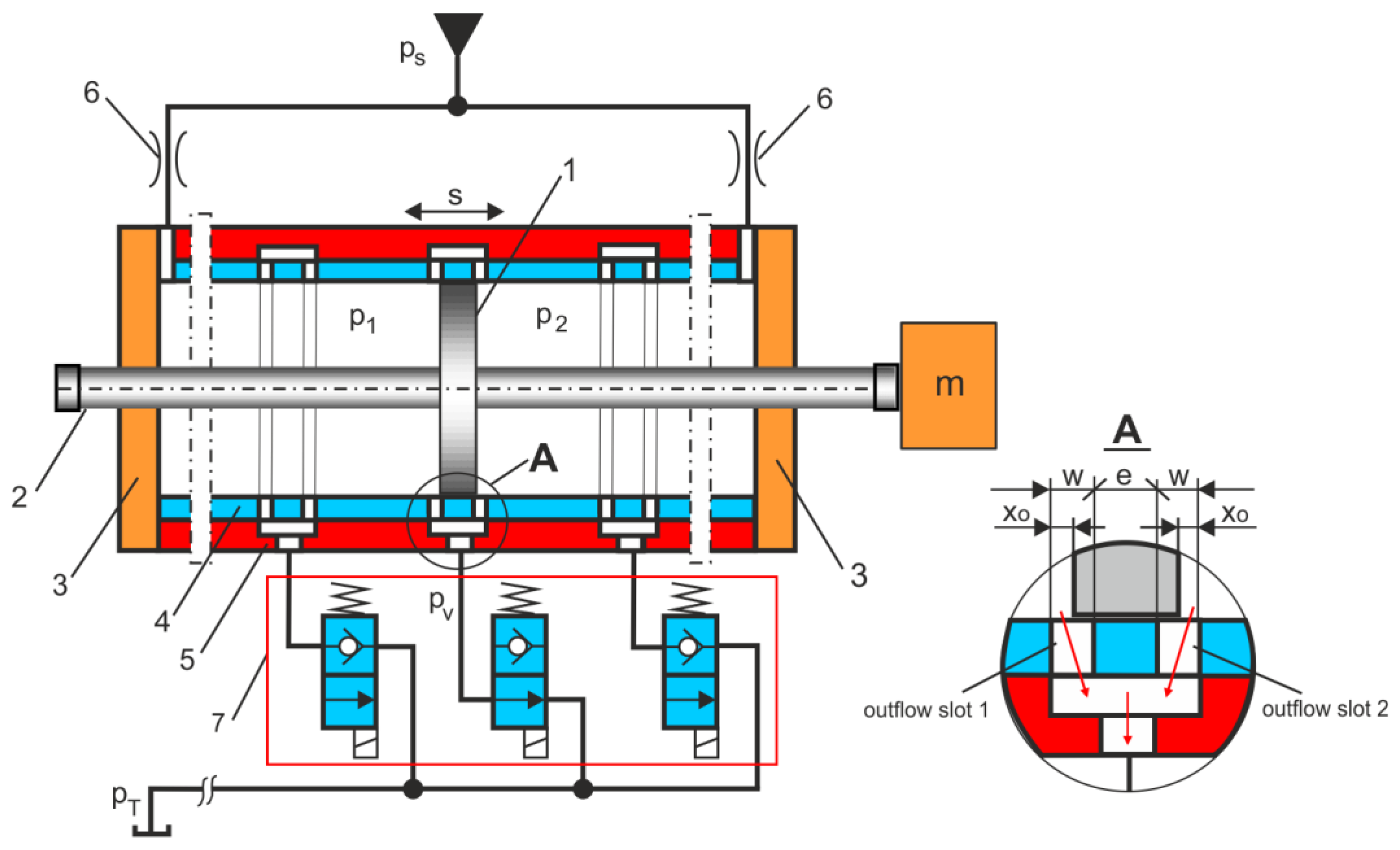
This study focuses on the design, dynamic modeling, and simulation of incremental step positioning using DIHPS. Compared to the conventional electrohydraulic servo system (EHSS), the EHSS provides a more accurate positioning than DIHPS. The EHSS is a feedback control system, while the DIHPS is an incremental control system based on fluid flow through the outflow gaps, hydraulic resistance balance, and force balance. EHSS uses a differential cylinder, while DIHPS uses a double-piston rod cylinder. Different pressure forces in the EHSS were impacted by the differential cylinder. Industrial EHSS includes a position controller without compensation or force control. To improve the tracking performance, an adaptive compensator is added to the EHSS in this case. The DIHPS’s positioning control is influenced by the balance of forces. Machining a DIHPS cylinder costs more than machining a servo cylinder. The cost of the servo valves and the EHSS control system is much higher than the BV in DIHPS. Mass-produced BVs are the most robust, small, and inexpensive compared to proportional and servo valves, contributing to lower investment and production costs. DIHPS’s advantage lies in its ability to accurately position large masses and compensate for excitation forces. Sensorless position control of DIHPS is highly desired in the field of heavy hydraulic industrial automation. The programming of BV has multiple advantages over servo-valves and proportional valves. BV control at the outlet, as in DIHPS, is definitely more advantageous than servo valve control at the inlet, as in EHSS.
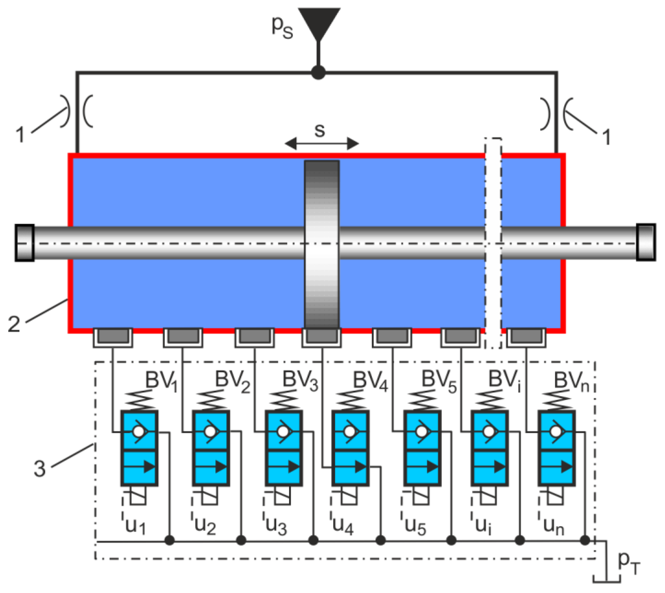
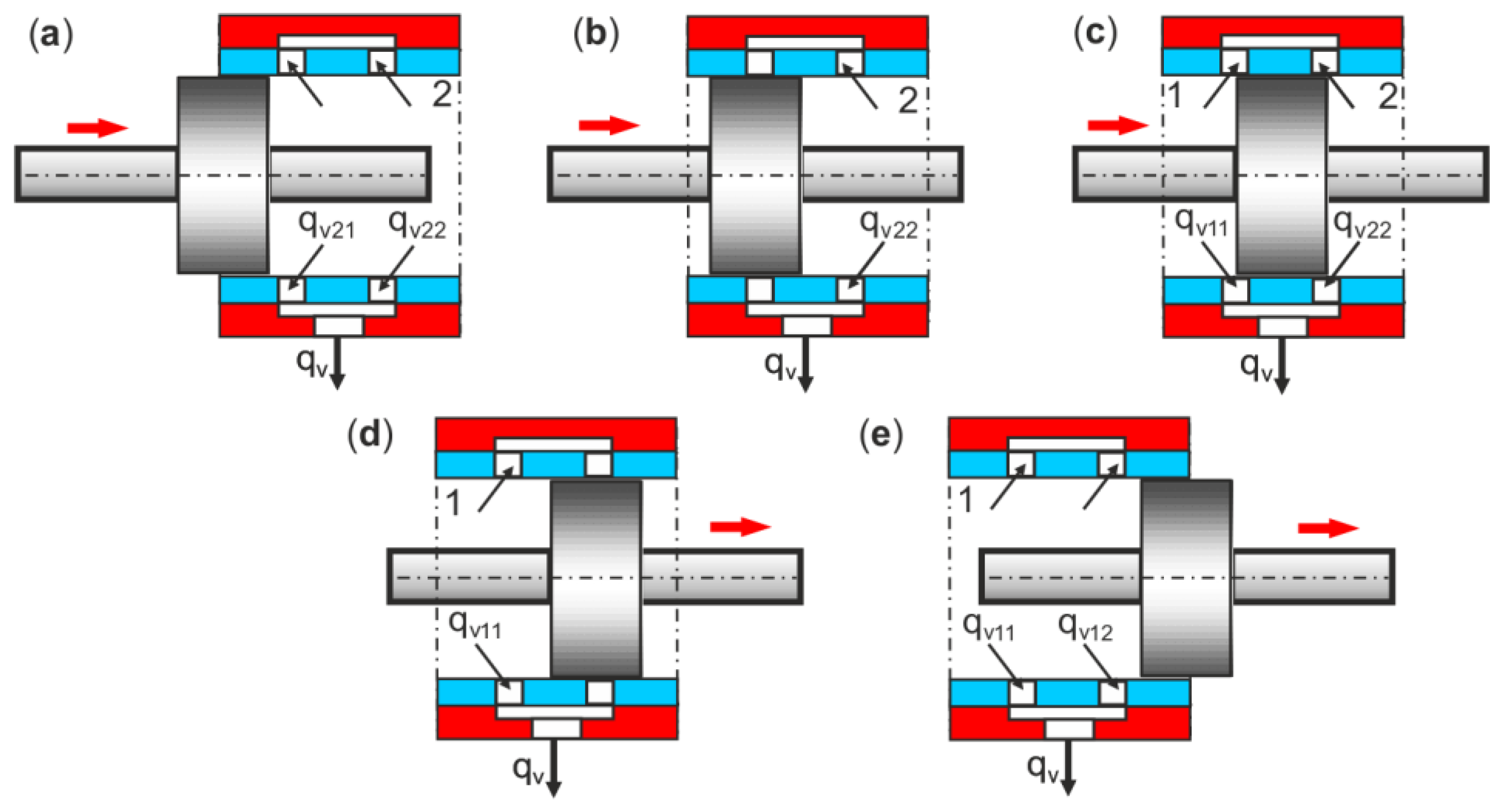
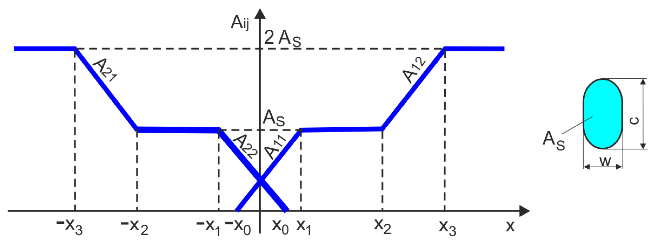
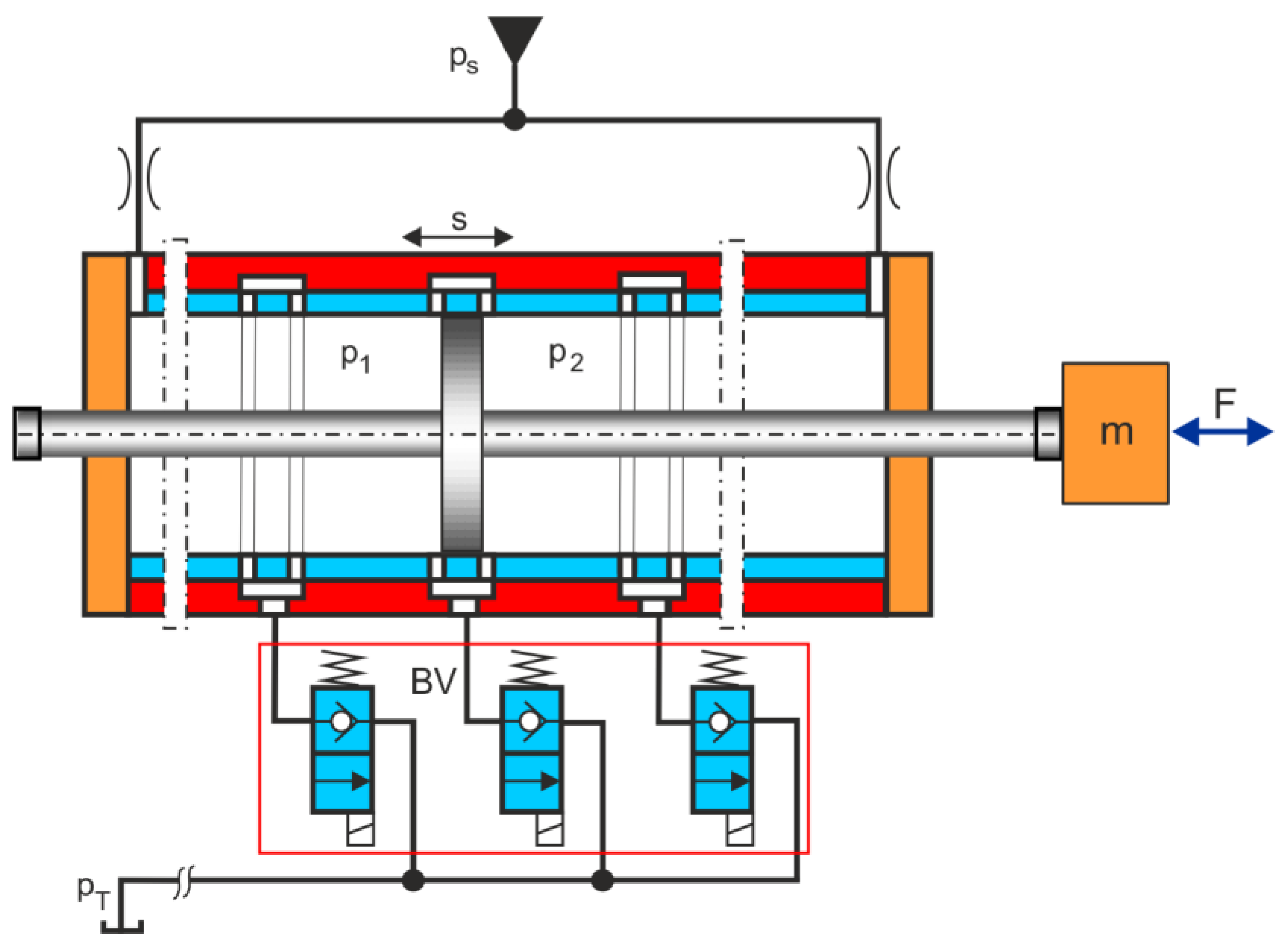
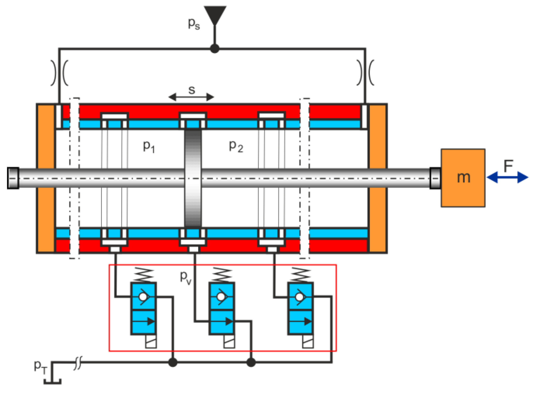
Figure 1 shows a general schematic diagram of the DIHPS, consisting of two fixed TRVs, a double-acting HPA with a double piston rod, and a block of BVs, which operate as bleed-off valves. Discrete incremental positioning using DIHPS involves a step shift in the HA piston from the starting position after closing the BV
4 valve, as shown in
Figure 1, to a new position after opening any BV
i valve. The actuator piston rapidly shifts to the outflow gaps, through which fluid flows from both chambers of the actuator and then bleeds off through the BV
i to the tank. The piston actuator assumed a new stable position, which was the result of the balance of the pressure forces acting on it. The discrete incremental positioning of the DIHPS takes place in equal
n-steps, depending on the opening of one of the BV
s (BV
1–BV
n). BV
s have two binary control states:
on (1) and
off (0). For solenoid BV
s, the
off state is the OV voltage signal, and the
on state is the 24 V voltage signal.
The incremental step control of DIHPS depends on the
BVi state, which can be expressed as follows:
From Equation (1), it follows that the Boole logic truth table has a constituent of ones, as shown in
Table 1.
The stroke length
S of the HA is as follows:
where
is the initial position, and
is the end position.
The HA incremental step length Δ
s is as follows:
where
n is the step number.
The incremental step shift of the actuator piston from the start position to the new position is calculated as follows:
where
is the new
i-th position after opening the valve
Vi, and
is the start
is position after closing the valve
Vs.
The absolute displacement of the actuator piston is as follows:
Incremental step positioning is achieved through the use of Equations (2)–(5). The simulation model uses these formulas to implement incremental step positioning.
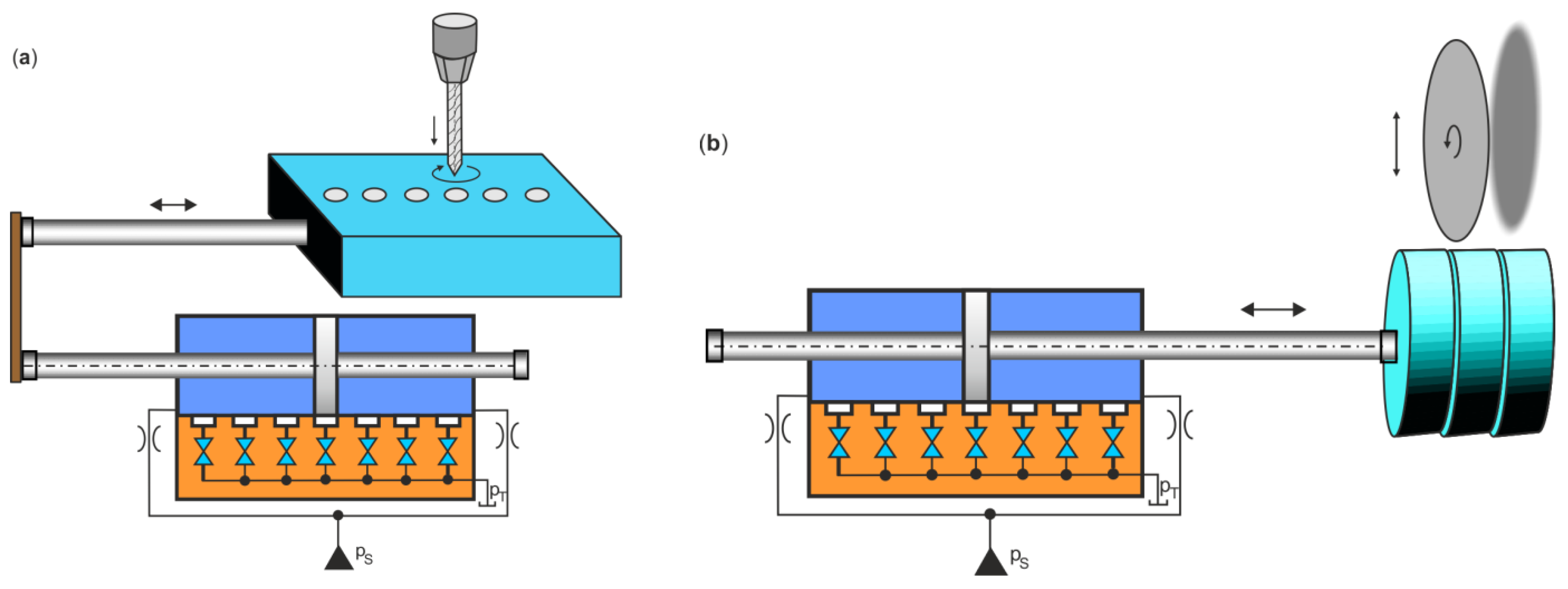
DIHPS can be used in heavy-industry automation, especially in cases where a strictly controlled and precise step shift of large loads is required. High-precision heavy industrial automation offers a number of advantages, including the management of heavy and awkward loads. Many manufacturing tasks lend themselves to automation in the heavy industry, where repeated heavy loads occur. DIHPS has a number of industrial applications, such as 3D printers, robots, laser devices, and the like. One of the key applications of DIHPS is XY tables, which require both high thrust forces and positioning accuracy. DIHPS can be used on roller mill tracks and conveyors in the diversion or sorting of heavy loads.
Figure 2 shows schematic diagrams of the application of DIHPS for the machining of heavy workpieces, such as drilling and cutting. In such cases, DIHPS must move the object with appropriate incremental step positioning.
After satisfactory experimental tests, DIHPS could be implemented for the machining processes of large-size heavy steel components at the Celsa Steel Mill (CSM) in Poland. CSM is a leading European manufacturer of open die forgings for strategic industries: power generation, oil and gas, engine, tool steel, and metal processing [
31]. Forged components are made for the world’s largest suppliers of wind turbines, high-power plant turbines, and global corporations in the energy and mining sectors.
4. Results of the Simulation Test
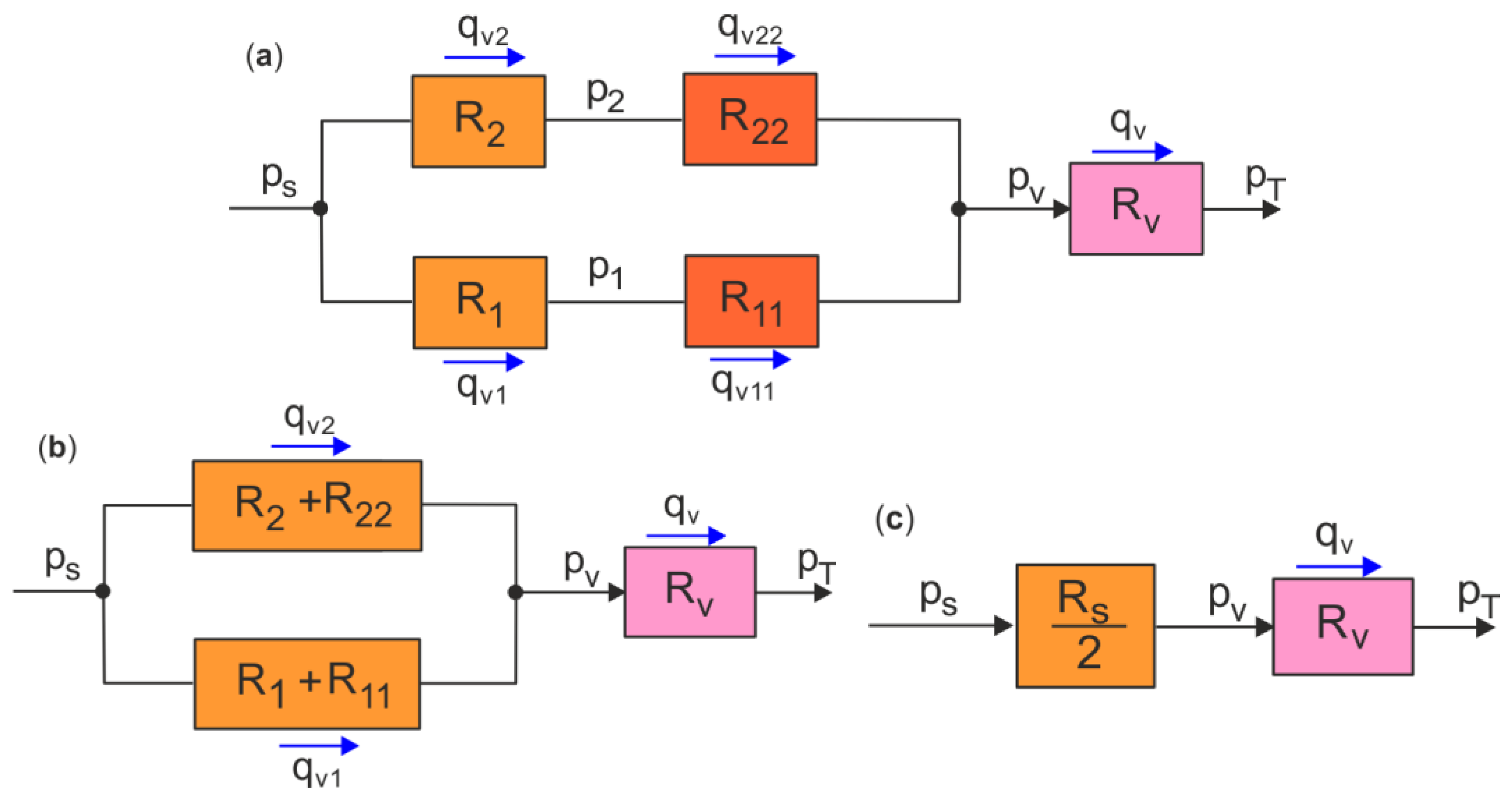
The accuracy of the DIHPS operation was verified using its dynamic model during simulation tests. In simulation tests, the dynamic responses of the DIHPS were examined during the step shift of the actuator piston. Before the simulation test, the selection of the hydraulic resistance at the stop position of the DIHPS was verified based on the hydraulic resistance circuits shown in
Figure 8.
In the stop position of the DIHPS, there is a balance of forces acting on the actuator piston and symmetrical hydraulic resistance on both sides of the piston,
and
The selection of unknown pressure
results from the equivalent hydraulic resistance,
In the simulation tests performed in the Matlab&Simulink R2020a software of MathWorks, the following basic parameters of constant values were introduced:
ps = 10 MPa,
m = 50 kg,
b = 2500 Nsm
−1,
D = 0.05 m,
d = 0.025 m,
S = 0.1 m,
K = 1800 MPa,
ρ = 860 kgm
−3,
R1 =
R2 = 8.26 × 10
11 Pa s
2 m
−8,
Rv = 3.9 × 10
11 Pa s
2 m
−8,
R11 =
R22 = 1.80 × 10
13 Pa s
2 m
−8, and the actuator piston step by
s = 0.02 m, and the piston step shift is
si = 0.02, 0.04, 0.06, 0.08, and 0.1 m. The full list of simulation parameters is provided in
Appendix A Table A1.
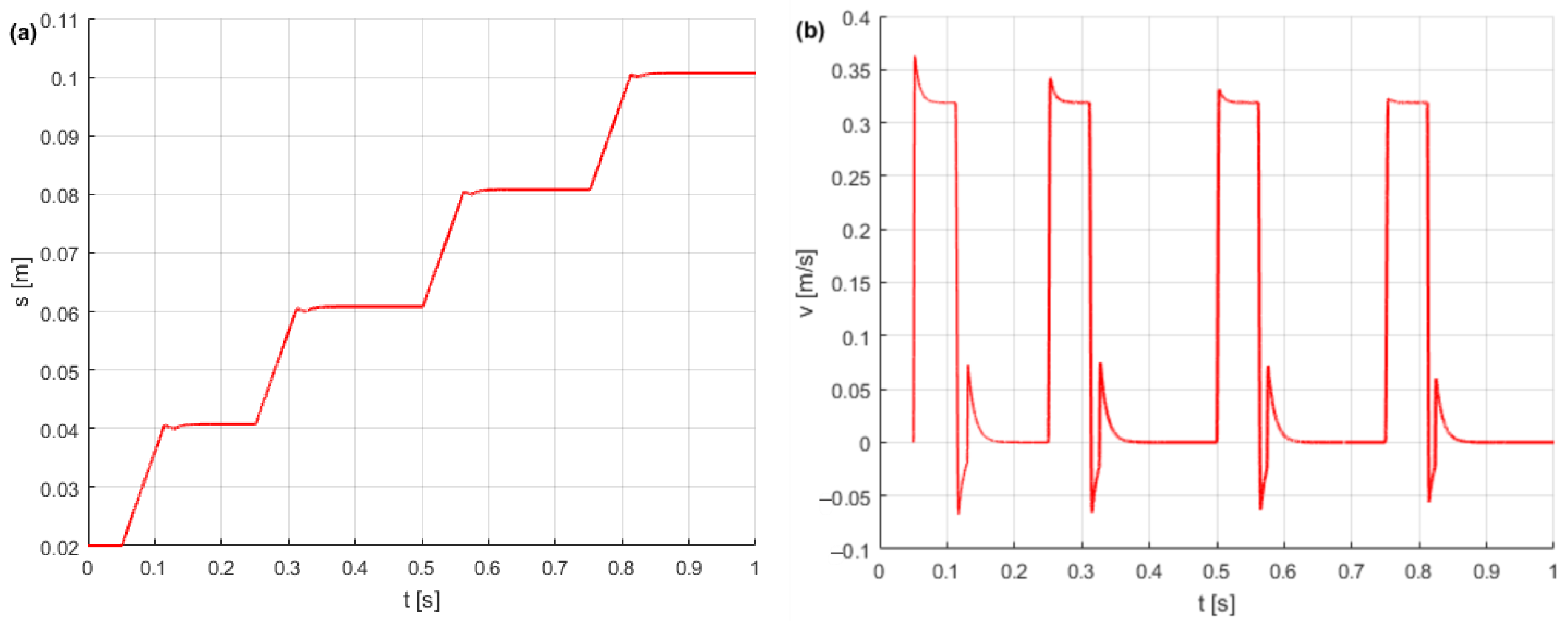
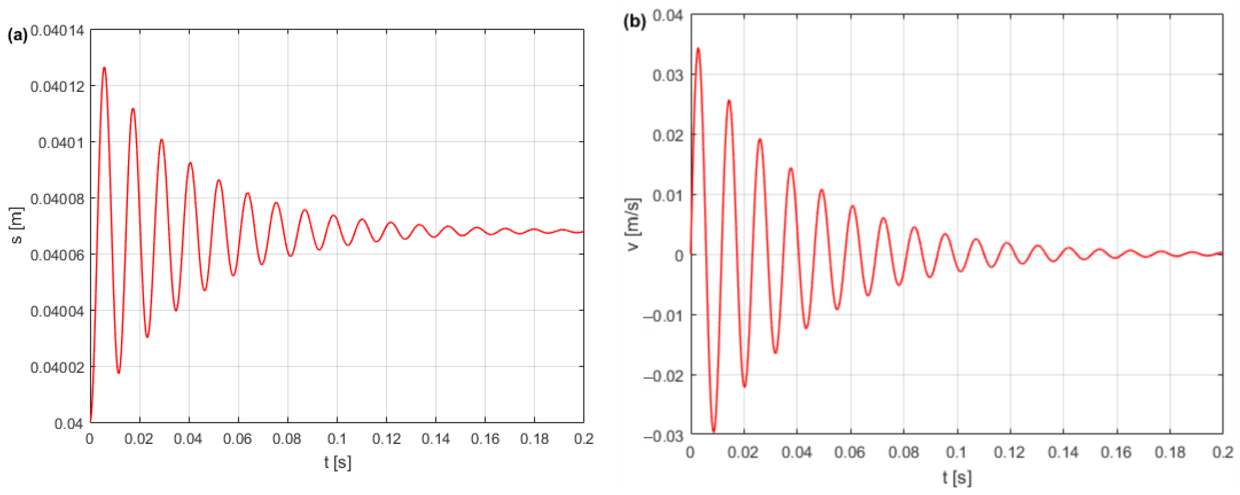
Figure 9 shows the dynamic response parameters of the DIHPS during step incremental positioning, the step shift
s of the actuator piston, the speed
of the actuator piston, and the pressure
p1 and
p2 in the actuator chambers.
Simulation tests confirmed the accuracy of the design assumptions, the functionality of the dynamic model, and the achievability of the specified incremental step shift of the DIHPS.
Based on the simulation results, it is possible to estimate the position error of the HA piston. The estimated step error
of the piston from
si for a set position
sis relative to step
s is expressed as follows:
The precision of the step position of the HA depends on the mass load because, already, for m = 50 kg, the ≈ 1%.
Typically, the positioning accuracy of an HA is related to the stroke length. The step error
of the piston estimated to the stroke length
S is as follows:
then you obtain
≈ 0.2% for
m = 50 kg.
A quantitative method was developed in [
34] to evaluate different hydraulic positioning structures based on specific influence factors.
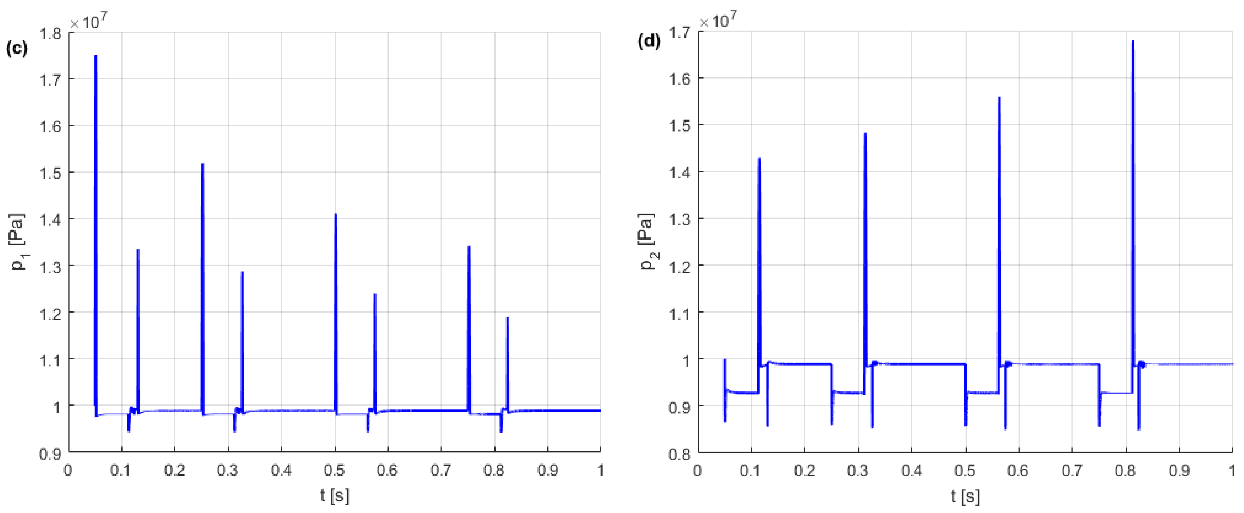
Dynamic characteristics show disturbances in the displacement and velocity of the actuator piston, as well as pressure peaks in the actuator chambers, which are the result of hydraulic shock when the BV is closed and opened. Hydraulic shock occurs when the hydraulic fluid flow suddenly stops or increases rapidly. Hydraulic shock is the result of the change in kinetic energy into potential energy (positive hydraulic shock) when the valve is closed or the change in potential energy into kinetic energy (negative hydraulic shock) when the valve is opened.
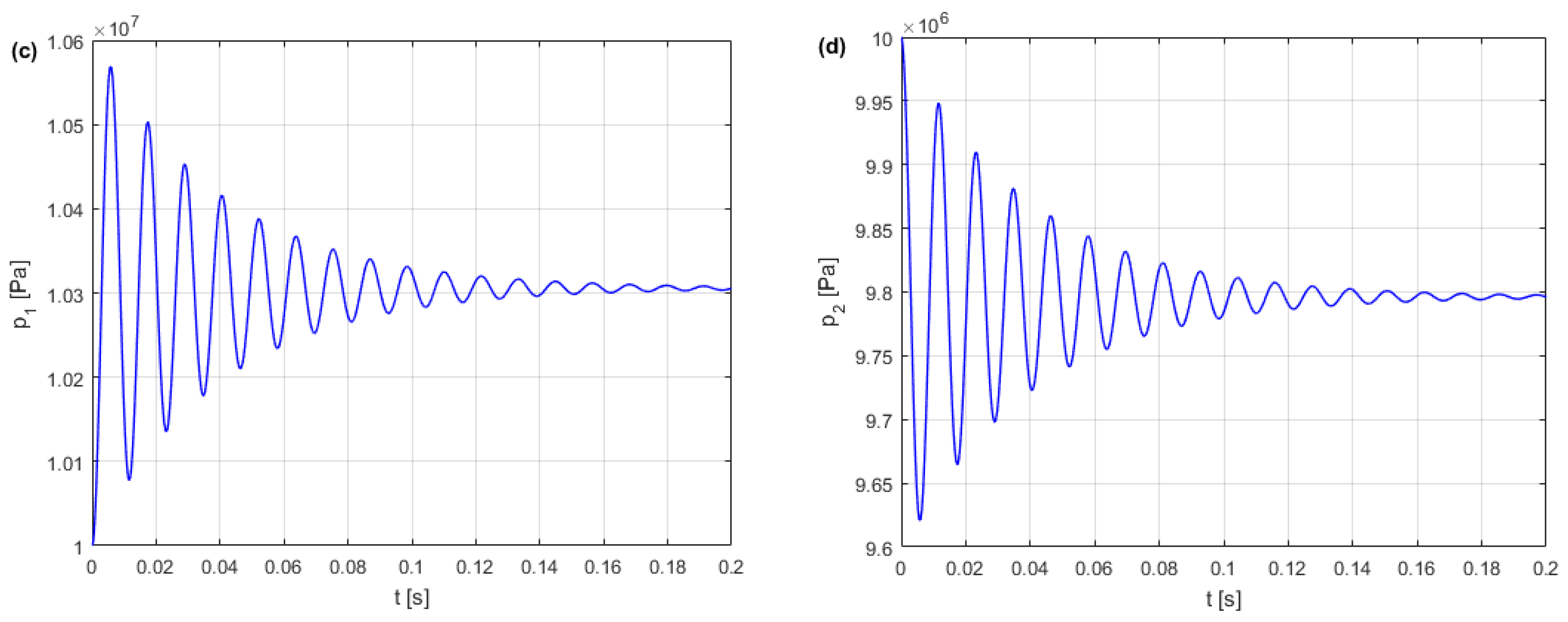
5. Hydraulic Stiffness of HA
Figure 9c shows the pressure peaks during the step shift of the actuator piston, with the highest pressure peaks occurring at extreme positions of the actuator piston. This phenomenon is caused by the compressibility of the hydraulic oil in the actuator chambers. Due to their compressibility, hydraulic fluids behave like hydraulic springs. The stiffness of the actuator chamber depends on the stiffness of the hydraulic oil and is defined as follows:
where
k1,
k2 are the hydraulic stiffness in the actuator chambers.
The shift of the actuator piston causes a change in the volume in both chambers in proportion to the effective area
A of the piston and inversely proportional to the hydraulic capacity
C1 and
C2, and thus the hydraulic stiffness of a symmetrical HA results from the series connection of the hydraulic oil springs as follows:
for 0 ≤
s ≤
S,
natural frequency
f of the HA under mass load,
For the simulation parameters adopted and step s = 0.04 m, the hydraulic stiffness HA is k(s) = 1.4 × 10⁷ N/m and the natural frequency is f(s) = 86 Hz.
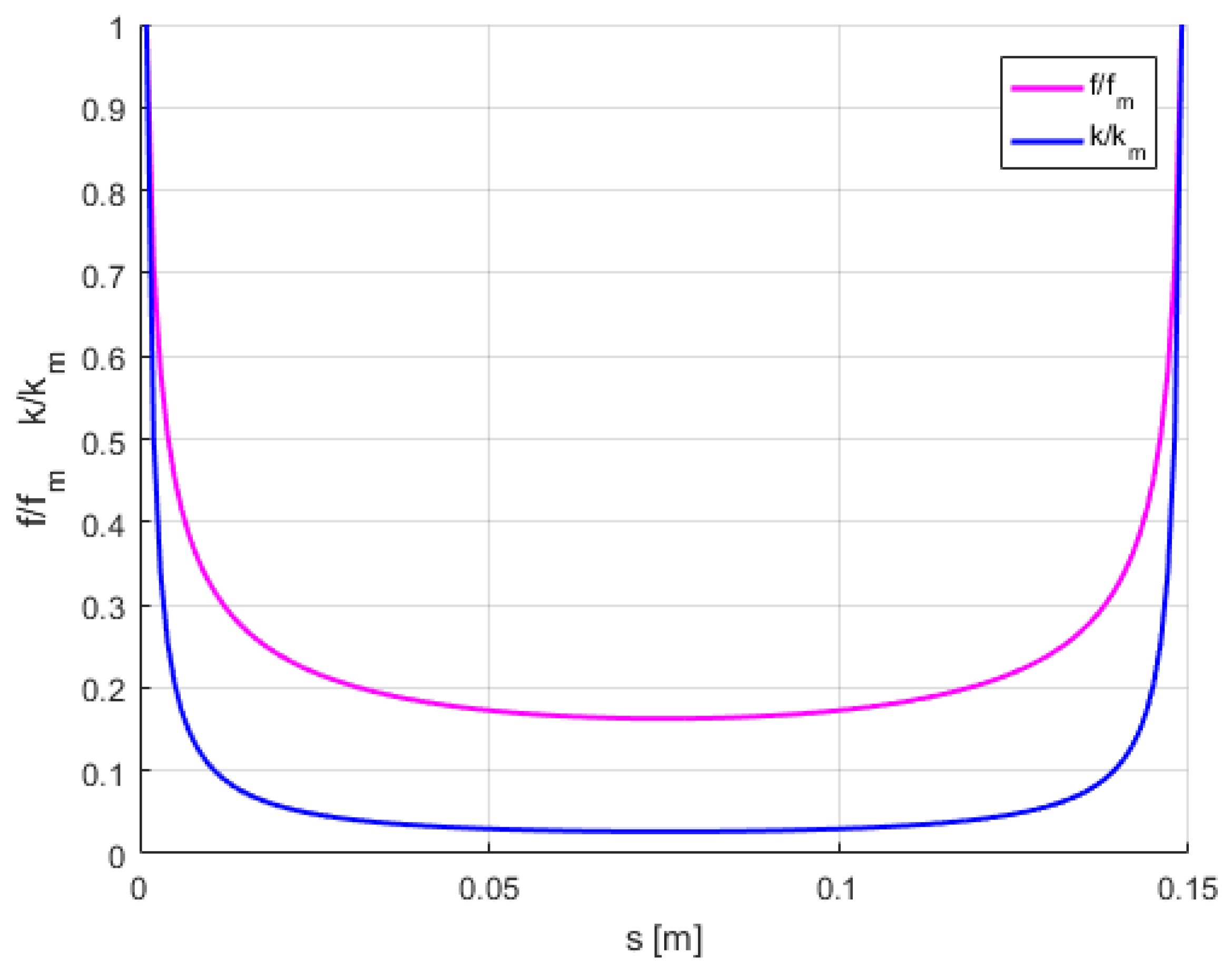
Figure 10 shows the relative hydraulic stiffness
and the relative natural frequency
of the HA as a function of piston stroke. Note that the stiffness
k(
s) and the natural frequency
f(
s) for
s = 0,
s =
S are infinite.
After reaching the assumed DIHPS step position and closing the BV, the HA becomes stiff, as shown in
Figure 11.
For a given piston step
s, the mechanical model of stiff HA excited by force
F is as follows:
Figure 12 shows the dynamic responses of a rigid HA excited by a constant force.
Figure 13 shows the resonance vibration parameters of a rigid HA excited by a cyclic force.
The hydraulic stiffness of the HA in the stop position influences the dynamic behavior of the DIHPS. HA subjected to load disturbances such as excitation force is susceptible to vibration. In an HA, there can be a wide spectrum of pressure pulsation frequencies [
35]. In the case of constant excitation force, the vibrations of the HA piston are suppressed, and the accompanying pressure pulsations disappear. When the HA is excited by a cyclic force, the vibrations are not dampened, and the accompanying pressure pulsations do not disappear. An excitation force limited to harmonic vibration was introduced to excite HA,
where
F0 is a constant excitation force, and
fe is the excitation frequency.
When a stiff HA is subjected to an external vibration generated by an excitation force of the same frequency as the HA frequency (f = fe), the actuator piston begins to vibrate and generate pressure pulsations.
Vibration resonance must be avoided because the maximum pressure pulsations that arise can seriously damage the hydraulic system and significantly shorten its life. If there are vibrations near the resonance, a pulse shock absorber (pressure pulsation damper) should be used in hydraulic pipelines connected to the HA. The HA parameters should be selected to avoid resonance vibrations. The natural frequency of the HA is usually higher than the frequency of the excitation force (f > fe).
6. DIHPS Dynamic Model with Excitation Force
The simulation tests presented in
Section 4 involved DIHPS incremental step shifts with a constant mass load of
m. In this section, the dynamic response of the stiff HA is verified by introducing a constant excitation force
F, which is a disturbance force. Currently, the dynamic model (34) is being considered, taking into account the constant excitation force
F,
Figure 14 shows a DIHPS diagram with a HA loaded with a bidirectional constant excitation force
F.
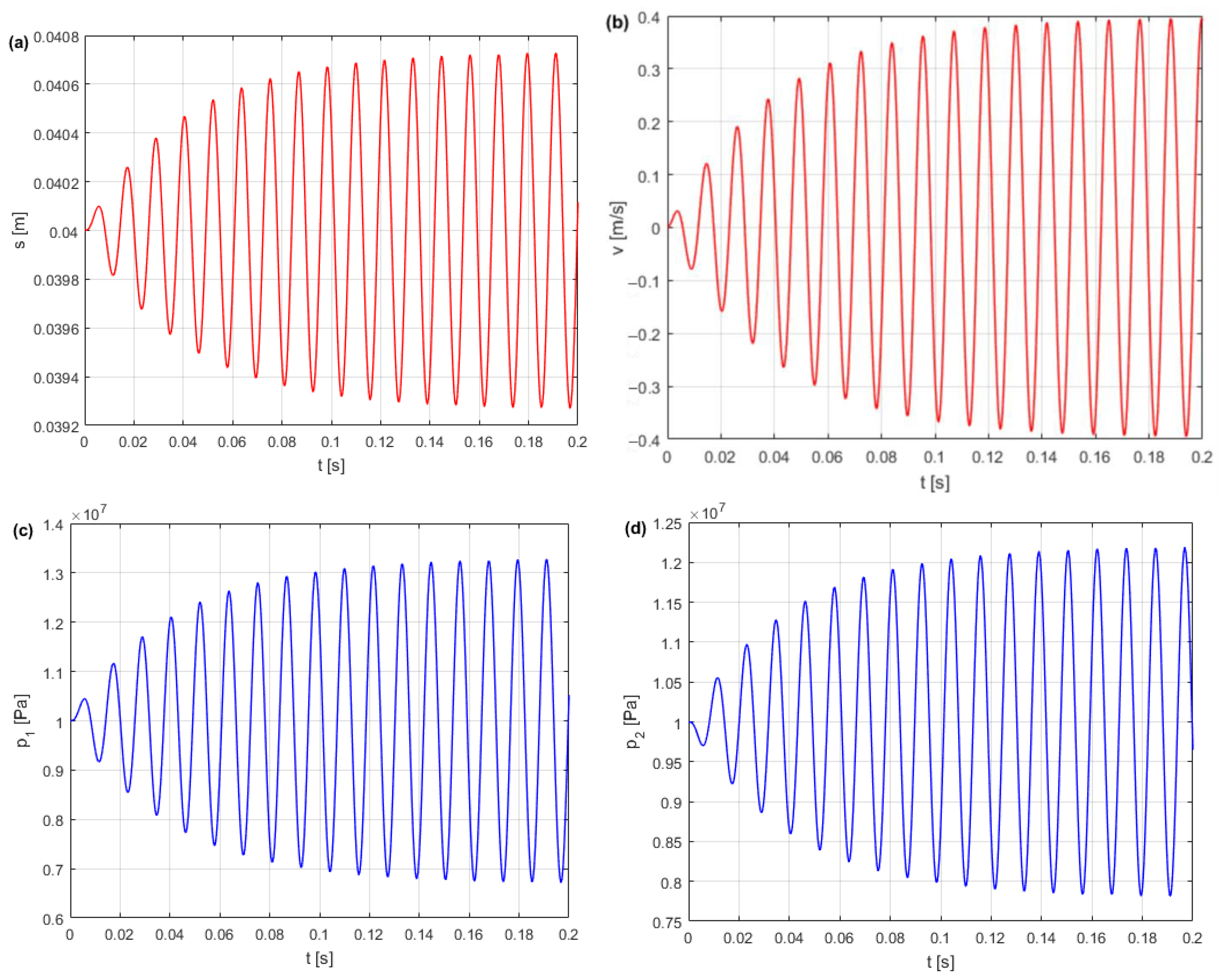
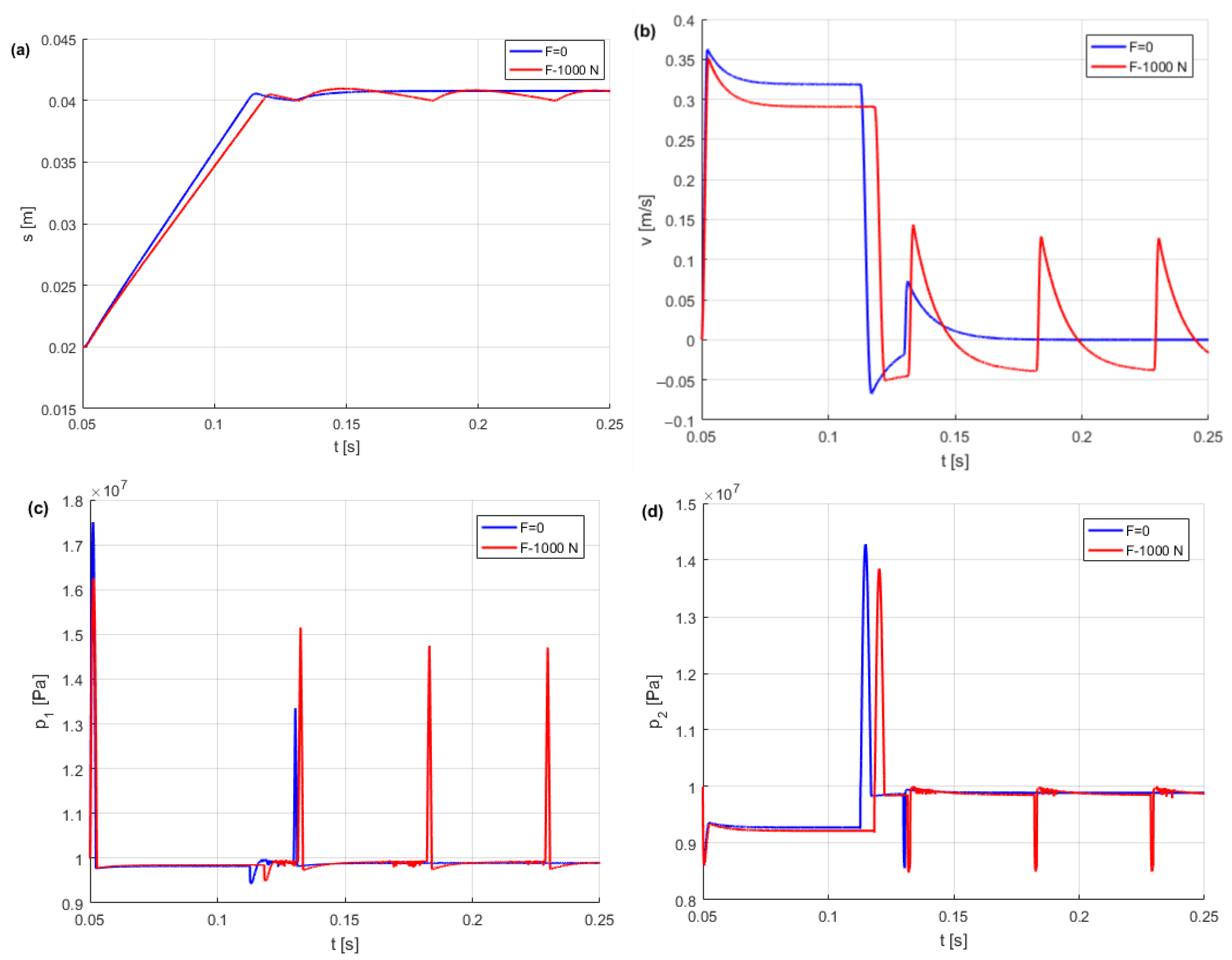
Figure 15 shows the dynamic response parameters of the DIHPS for a single-step shift of the piston actuator with and without a constant excitation force.
The dynamic response of the actuator piston during a single-step shift was analyzed after introducing a constant excitation force F = 1000 N. After introducing a constant excitation force, cyclic piston vibrations, piston speed jumps, and pressure peaks were observed. These disturbed the piston’s position and affected the accuracy of step incremental positioning. To improve the accuracy of step-incremental positioning of HA subjected to an excitation force, HPA pressure pulsation damping was used.
7. DIHPS Dynamic Model with HPA
The HPA was connected to the actuator chamber to effectively dampen piston vibrations and pressure peaks. The HPA is a gas-charged accumulator with a hydraulic fluid chamber and a gas (nitrogen) chamber separated by a gas-tight partition (piston, bladder, and diaphragm). A diaphragm (membrane) type HPA was used as a pressure-pulsation damper [
36].
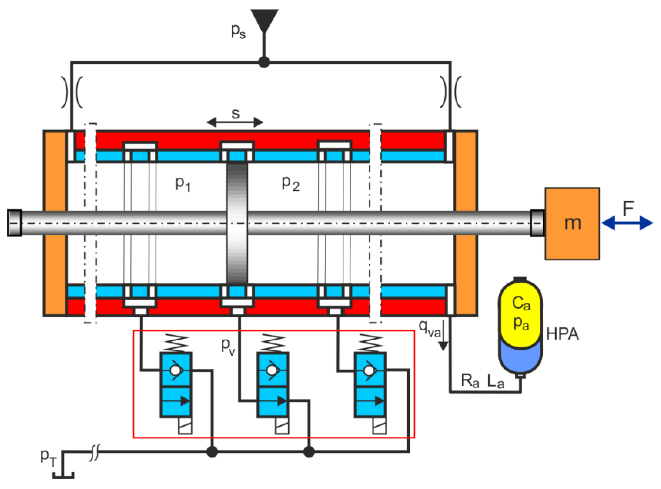
Figure 16 shows a diagram of the DIHPS with the HPA connected to the actuator chamber on the
F side.
The dynamic model (51) of the DIHPS supplemented with the flow rate balance in the actuator chamber is as follows:
The HPA and the hydraulic tube connecting to the actuator chamber can be modeled with lumped elements connected in a series
RLC (
R is the hydraulic resistance,
L is the hydraulic inductance, and
C is the hydraulic conductance), according to the analogy between hydraulic and electric circuits [
37,
38].
The HPA model contains two first-order differential equations, the flow rate equation in the connected tube and the gas compressible equation, as follows:
The notation of Equation (51) in numerical solutions is as follows:
where
is the flow rate in the hydraulic tube,
p2 is the fluid pressure in the actuator chamber, and
pa is the gas pressure in the HPA,
Ca is the gas capacitance of the HPA,
where
p0 is the initial pressure (
p0 = 4 MPa),
V0 is the initial volume (
V0 = 0.001 m
3), and
κ is the adiabatic exponent in the case of a diatomic gas as N
2 nitrogen (
κ = 1.4).
La is the hydraulic inductance of the hydraulic tube (hydraulic inductance describes the pressure difference required for a change in flow rate and is based on mass inertia),
where
ρ is the density of hydraulic oil,
lh is the length of the hydraulic tube (
lh = 0.05 m), and
Aa is the cross-section of the hydraulic tube,
where
dh is the diameter of the hydraulic tube (
dh = 0.005 m).
In the HPA connecting tube during hydraulic shock, the kinetic energy is converted into potential energy; therefore, the hydraulic resistance caused by the pipe impedance refers to the wave resistance inside a tube,
where
a is the wave propagation speed (speed of sound in the fluid),
It is important to note that the hydraulic resistance caused by the flow resistance is smaller than the hydraulic resistance caused by the wave resistance.
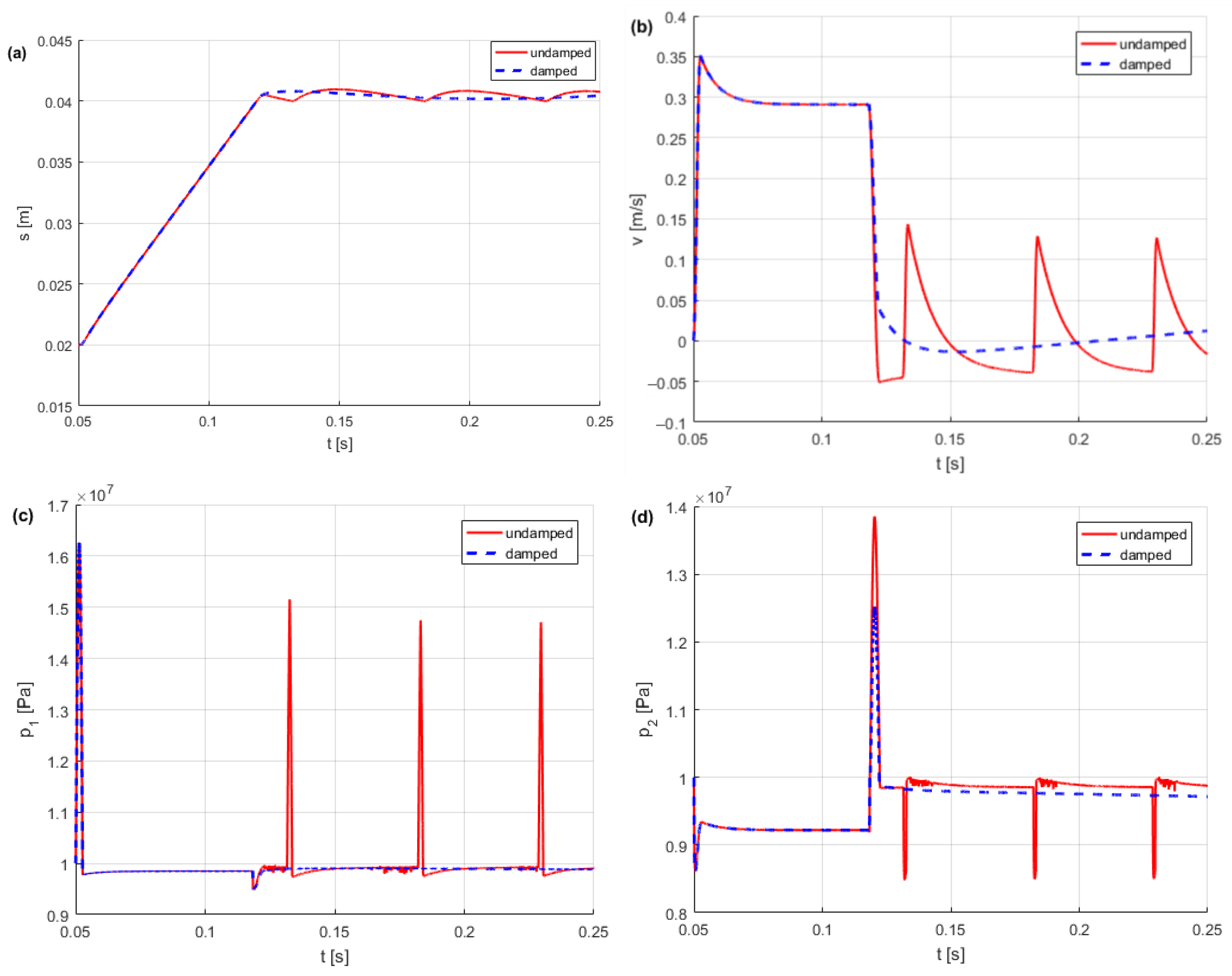
Figure 17 compares the undamped and damped DIHPS dynamic response parameters for a single-step shift of the actuator piston with a constant excitation force of
F = 1000 N, representing the disturbance force. By comparing the dynamic responses of DIHPS shown in
Figure 17, the effectiveness of HPA was demonstrated in damping piston vibrations and pressure peaks in the actuator chamber. Pressure peaks and piston vibrations caused a decrease in the accuracy of the DIHPS position. HA pressure peaks cause pressure fluctuations in hydraulic pipelines and connecting elements, which contribute to mechanical vibrations, fatigue damage, and harmful noise. The mechanical vibrations of the actuator piston affect devices and machines, leading to their failure or even damage to structural elements. Usually, piston vibrations and pressure pulsations caused by external forces are not considered in HA.
8. Conclusions
This article presents a new DIHPS operating principle, its original dynamic model with a simulation solution, and an HA stiffness model considering an HPA. The incremental step shift of the DIHPS is possible due to its new design concept and the principle of operation, consisting of the symmetrical arrangement of the outflow slots in relation to the actuator piston, through which the fluid flows from the actuator chambers to the open i-th BV at the bleed off to the tank. The advantage of placing BVs at the bleed to the tank is that flow disturbances are not generated in the HA, as is the case with inlet valves.
Since there is no similar solution to DIHPS, the factors that determine the properties of DIHPS compared to other positioning methods are highlighted:
- -
positioning speed: high; the opening size of the BV can be large;
- -
positioning accuracy: low, large radial clearance between cylinder and piston;
- -
positioning resolution: low, limited distances between the outflow gaps;
- -
positioning range: low, limited number of outflow gaps;
- -
response speed: high; opening of the BV can be quick;
- -
working force: low, the chambers on both sides of the piston are supplied with pressure fluid;
- -
cost: medium, simple structure, and moderate requirements for component machining precision;
- -
location limit: high; location depends on positioning resolution and positioning range.
In DIHPS, reliability, repeatability, fault tolerance, zero leakage, low operating cost, and lower cost of spare parts are the most important.
Simulation tests confirmed the accuracy of the design assumptions, the functionality of the dynamic model, and the achievability of the specified DIHPS incremental step shift. The hydraulic resistance of the DIHPS was verified on the basis of the circuit of the hydraulic resistance. After reaching the set incremental step position, the DIHPS entered the stop position, where the stiffness of the hydraulic oil in the actuator chambers was significant. An HA stiffness model was defined for the DIHPS stop position to determine the relative hydraulic stiffness and natural frequency as functions of the actuator piston position. The dynamic response parameters of the HA stiffness for a single-step shift of the piston actuator were verified with and without constant excitation force. Hydraulic stiffness has been shown to have a significant impact on the dynamic behavior of the DIHPS in the stop position. The HPA is connected to the actuator chamber to effectively dampen the vibrations of the piston, and the pressure peaks at the stop position of the HA. The HPA and hydraulic damping tube connected to the actuator chamber were modeled using a lumped element RLC connected in series. The damping effectiveness of the HPA was proven by comparing the damped and undamped dynamic response parameters of the HA for a single-step shift of the actuator piston. The results of the simulation tests were used to develop a DIHPS prototype that was subjected to experimental tests. The execution of DIHPS is complex, as it requires precise machining of step-distant outflow gaps.
Incremental step positioning using DIHPS is simpler and cheaper because it operates in an open loop without feedback, which is beneficial in heavy industrial automation to position large masses in shipbuilding, mining, steel mill, metallurgy, and construction.


