Article

Design and Simulation of a Multi-Channel Biomass Hot Air Furnace with an Intelligent Temperature Control System

1
College of Mechanical and Electrical Engineering, Hunan Agriculture University, Changsha 410128, China
2
Hunan Key Laboratory of Intelligent Agricultural Machinery and Equipment, Changsha 410128, China
*
Author to whom correspondence should be addressed.
Agriculture 2024, 14(3), 419; https://doi.org/10.3390/agriculture14030419
Submission received: 7 February 2024 / Revised: 27 February 2024 / Accepted: 2 March 2024 / Published: 5 March 2024
(This article belongs to the Section Agricultural Technology)

Abstract

:
Timely and effective drying of agricultural products is crucial for ensuring the quality and yield of grains. Biomass drying enhances energy utilization and reduces energy pressure. To this end, a novel multi-channel circulating biomass hot air furnace was designed to provide precise control of the heat source for grain drying, thereby improving the efficiency and quality of the drying process. The combustion process utilizes a multi-channel combined air supply to ensure complete combustion of biomass pellet fuel. During the heat exchange process, heat exchange plates isolate hot and cold areas, discharging combustion exhaust, while ensuring a pure air output. Using rapeseed as the drying subject, a temperature controller based on adaptive fuzzy PID was designed, targeting the biomass hot air furnace’s heat exchange system for modeling and verifying the model with the step response method. Model simulations were conducted in Matlab’s Simulink module using both adaptive fuzzy PID and traditional PID controllers, for a given signal. The settling times for the conventional PID and fuzzy PID were 445 s and 364 s, respectively, with overshoots of 20.1% and 6.3%, showing that the fuzzy PID controller performed better in terms of control performance. The validation tests showed that both control methods could maintain the temperature within ±5 °C. Compared to traditional PID control, the adaptive fuzzy PID control achieved a precision of ±3 °C. At the target temperature of 90 °C, the error was reduced to 3.7%, with a stabilization time of 1014 s. The use of fuzzy PID control exhibited better dynamic response characteristics, meeting the drying needs of rapeseed. This study provides a theoretical basis for the structural design and control system design of biomass hot air furnaces.

1. Introduction

In the context of “carbon peaking and carbon neutrality”, biomass pellet fuel as a drying heat source holds great potential for development [1,2,3]. Drying agricultural products is a crucial step in agricultural production and an important component of the entire mechanization process of grain production [4]. Conventional hot air drying uses coal as the heat source, but biomass fuel, as an important sustainable energy source [5], offers a viable alternative. Using biomass combustion to exchange heat for drying agricultural products is easy to operate and cost-effective. However, the temperature control process in these systems involves a large capacity, significant time delays, and non-linearity [6], making it challenging for traditional PID control systems with a single set of PID parameters to meet the requirements of dynamic adjustment and steady-state output during the drying process.
Jun Huang designed a small-scale domestic biomass pellet burner, conducting a thorough analysis of its structure and combustion characteristics. Using the fluent module in CFD 2024 software, the airflow and temperature fields post-combustion were simulated. The assembled prototype achieved a combustion efficiency of over 95%, with a fuel utilization rate reaching 85%, meeting the requirements for efficient fuel use [7]. Lei Yu introduced structural and key combustion technologies for biomass molded fuel stoves, conducting combustion tests with corn straw molded fuel. By adjusting the ratio of secondary air volume, air intake position, and inflation angle, a comparative analysis of the combustion effect was carried out, resulting in satisfactory combustion performance [8]. Bin Liu and others [9] designed a fuzzy PID control algorithm for a rapeseed hot air drying control system based on a hot air furnace. The research conducted a detailed study on the combustion conditions of biomass burners, yet there is room for improvement in research on precise temperature control.
Research on hot air furnaces began early in Western countries. Joseph D. Smith utilized computer-aided engineering design, combining effective optimization algorithms with existing CFD models. Through performance simulation, he sought the optimal operating conditions for biomass combustion furnaces and proposed optimization and improvement plans, thereby systematically enhancing the comprehensive performance of the device [10]. Pereira Júnior, Modesto, and others designed a fuzzy multivariable controller for rotary dryers, applying it to fertilizer drying to achieve reliable temperature control. This controller also reduced biomass consumption by 9% [11]. Lukas Böhler and his team proposed a small-scale grate fuzzy model predictive controller based on a biomass combustion model, selecting several local linear controllers as operating points and using gap metrics. The local predictive controllers combined with membership functions formed a global nonlinear fuzzy control structure. Comparisons between the fuzzy model predictive controller, linear model predictive controller, and PI control algorithm in closed-loop simulations showed that the fuzzy model predictive controller performed better [12].
Currently, biomass combustion equipment still faces challenges such as the difficulty of stable combustion, high pollution emissions, and inadequate temperature control capabilities [13,14,15]. During the drying process, temperature control faces numerous challenges, including achieving higher precision and stability, balancing energy efficiency with effective control, system response delays, and the design of the drying equipment. By making biomass a more efficient and manageable source of energy, biomass can drying contribute to the integration of renewable energy sources into the energy mix. This can help to reduce reliance on fossil fuels, thereby reducing the overall energy pressure and contributing to energy security. Biomass drying can also contribute to waste management by converting agricultural, forestry, and urban waste into energy. This not only reduces the waste that would otherwise end up in landfills but also turns it into a valuable resource.Improving the structure and operating conditions of biomass hot air furnaces through simulation, optimizing combustion efficiency, and applying advanced control theories to the temperature control of drying processes, thereby enhancing industrial performance, may become trends in future research.
This article presents the designing of a multi-channel auxiliary combustion biomass hot air furnace, which uses a multi-channel combined air supply to ensure complete combustion of biomass pellets. A plate-type heat exchanger isolates high-temperature combustion gases and the air requiring heating, maintaining the purity of the air at the outlet. By considering factors such as the inlet environmental temperature, fuel input, and fan speed that affect outlet temperature, a mathematical model of the furnace’s combustion and heat exchange system was constructed. With the goal of controlling the outlet temperature of the hot air furnace, an adaptive fuzzy PID-based temperature control system was designed. Taking the drying requirements of rapeseed as an example, experiments compared the performance of traditional PID controllers and adaptive fuzzy PID controllers in temperature control, thereby improving the quality of biomass hot air furnaces in grain drying.

2. Structure and Working Principle of the Biomass Hot Air Furnace

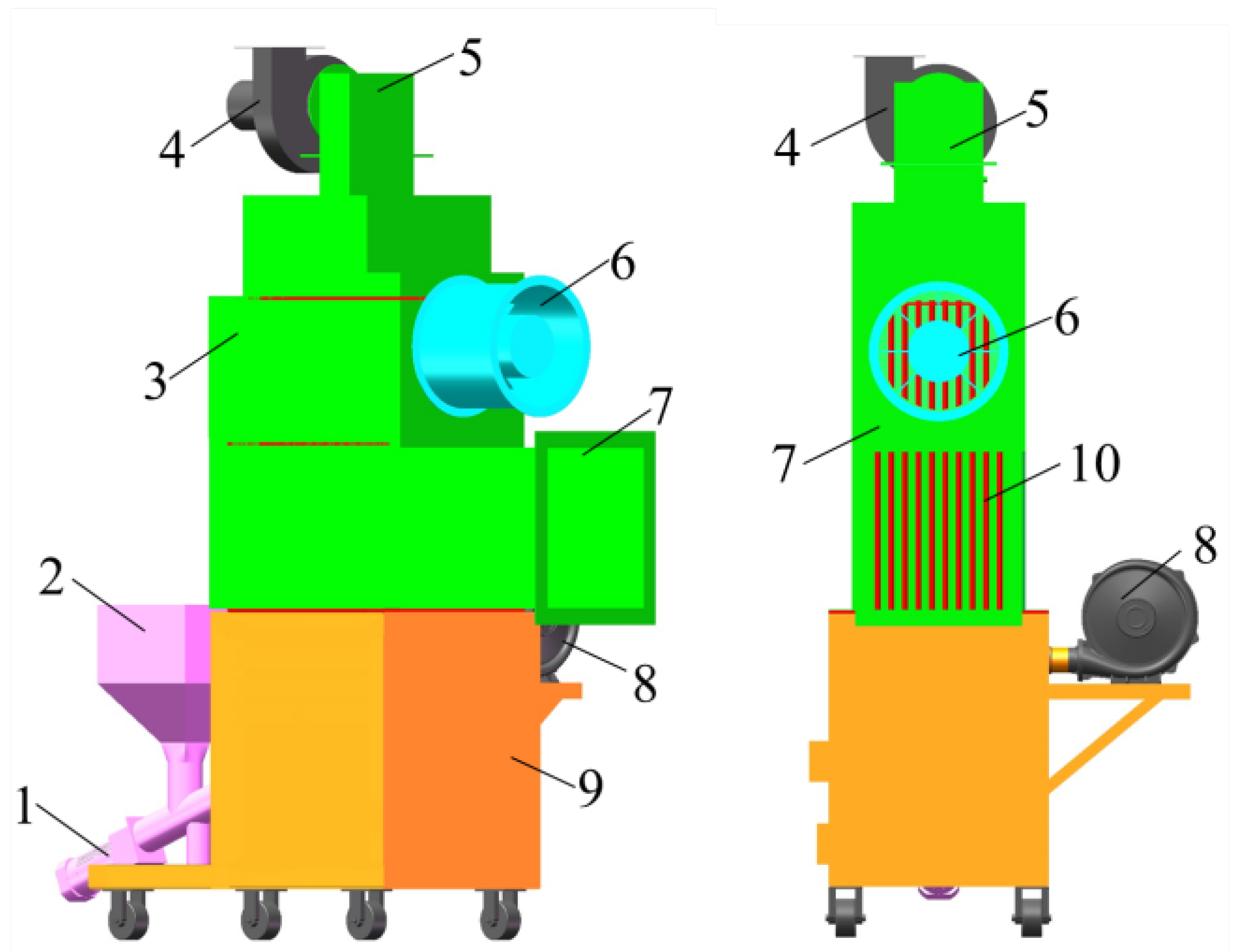
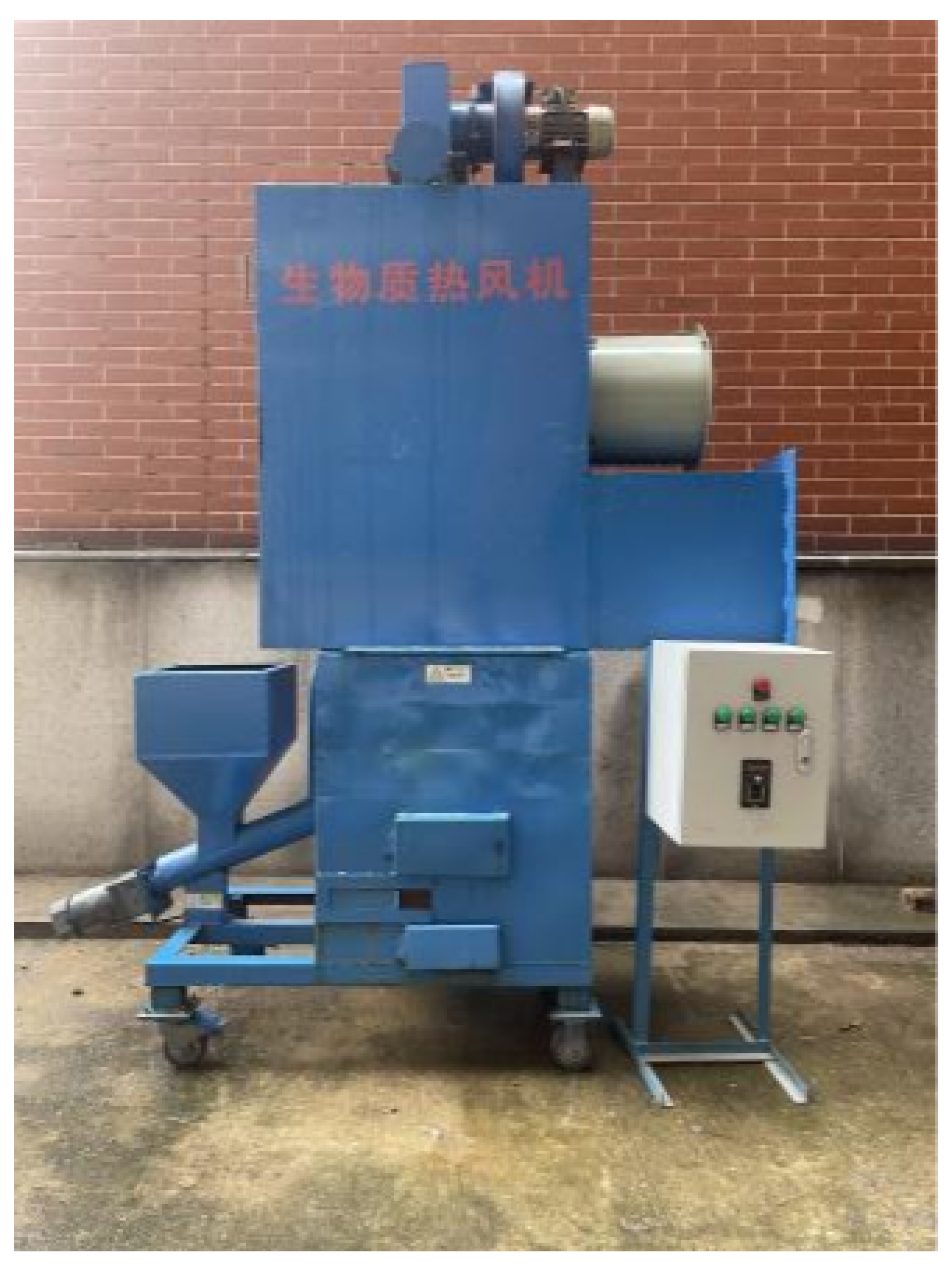
2.1. Structure of the Biomass Hot Air Furnace

As shown in Figure 1, the biomass hot air furnace is composed of a feed motor, hopper, furnace, heat exchange chamber, heat exchange plates, blower, induced draft fan, auxiliary combustion fan, and other components. The feed motor has a power of 250 W and uses single-phase AC stepless speed control. The auxiliary combustion fan has a rated power of 100 W and a rated speed of 2800 r/min. The induced draft fan has a power of 250 W, a rated speed of 2800 r/min, and a rated air volume of 860 m3/h. The blower has a rated power of 250 W, a rated speed of 1450 r/min, and a rated air volume of 3200 m3/h. Both the induced draft fan and blower are controlled by frequency converters.

2.2. Working Principle of the Biomass Hot Air Furnace

The biomass hot air furnace operates using an inclined feeding method, where biomass pellet fuel is manually poured into the hopper. As the feeding motor starts, the auger conveys the biomass pellet fuel into the furnace chamber below, accumulating above the grate. The biomass pellets are ignited using a high-temperature, wind-resistant flame gun. Once ignited, the pellets burn inside the furnace chamber. The top-mounted induced draft fan is then activated to expel the combustion exhaust gases and some residues through the top exhaust outlet. During the combustion process, the hot gases exchange heat with ambient air in the heat exchange chamber of the hot air furnace. When the actual temperature is below the set temperature, the supply of biomass pellet fuel will be increased, along with an increase in the frequency of the combustion air fan, blowing in more air to accelerate the combustion process, thereby achieving a rapid increase in temperature. As the temperature approaches the set point, the entire process will slow down. This is a dynamic process.After the heat exchange has been completed, the heated air is expelled from the lower outlet, which is then used for the subsequent grain drying processes. To shut down the furnace, the screw feeder is stopped first. The furnace is fully turned off, including all fans, once the flames inside the chamber are extinguished and the temperature drops to 200 °C [16]. The flow of materials and gases inside the biomass hot air furnace is illustrated in Figure 2.

3. Key Component Design

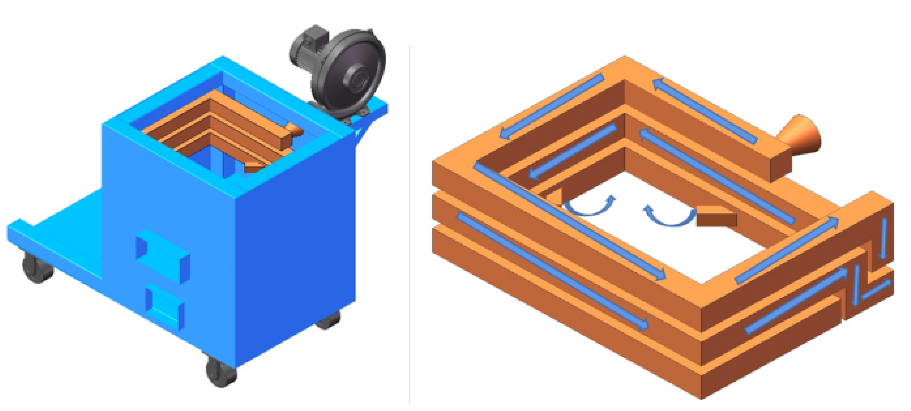
3.1. Multi-Channel Combustion Air Duct

In response to the high volatile content of biomass pellet fuel, the biomass hot air furnace adopts a multi-stage air distribution approach. The combustion air duct is shown in Figure 3. One air passage is arranged above the grate, entering the combustion chamber along with the biomass pellet fuel via the feed motor. This part of the air flow is relatively small. The other air passage involves air drawn by the auxiliary combustion fan, which circulates within the furnace wall for heating. The heated air then enters the combustion chamber through the inner wall pipe outlets, forming a spiral airflow field that promotes complete combustion in the chamber and reduces harmful gas emissions.
A surrounding air duct is located on the inner wall of the combustion chamber. The auxiliary combustion fan introduces air from the top, layer by layer downwards, with four rectangular outlets, each with a side length of 5 cm, at the bottom for air input. The arrangement of the surrounding air duct serves several purposes:
1.
providing sufficient air volume to ensure complete fuel combustion when the air in the furnace chamber is insufficient for fuel combustion;
2.
the inner wall pipe carrying ambient air acts to cool and protect the furnace walls;
3.
the four outlets simultaneously create a spiral airflow at the bottom, promoting combustion and reducing black smoke and volatiles;
4.
the ambient air heats up as it passes through the pipes, reducing heat loss.
Taking rapeseed drying as an example, let us consider a drying requirement of 200 kg/h with a moisture content of 9%. Assume the initial moisture content of the rapeseed is 25%, the drying inlet temperature is 25 °C, and the outlet temperature is 50 °C.
Q z = Q s + Q y Q r
Here, Q z represents the total heat required for drying, Q s is the heat consumed for evaporating moisture, Q y is the heat consumed for heating the grains, and Q r is the heat loss from the hot air furnace’s pipes and walls.
Q s = m 1 ν Q y = m 2 c Δ t
where m 1 is the mass of water to be dried, and ν is the latent heat of vaporization for the grains. m 2 is the mass of the dried grains, c is the specific heat capacity of the grains (rapeseed), and Δ t is the temperature difference.
From these calculations, the heat consumed for evaporating moisture is 36,018 kcal, the heat consumed for heating the grains is 2150 kcal, and the reference value for heat loss from the hot air furnace’s pipes and walls is 408 kcal. Thus, the total heat required for drying is 37,760 kcal.
After calculating the heat required for drying, the required mass of biomass pellets can be determined.
m 3 = Q z H L × η
where m 3 is the required mass of biomass pellets; H L is the lower heating value of the fuel; η is the combustion efficiency, here taken as 0.75. The required mass of biomass pellet fuel is 14.38 kg.
Theoretically, the amount of air needed for the combustion of each kilogram of fuel is [17],
V L = O t 0.21 V Z T = m 3 × V L 10 %
In practice, the airflow provided by the inner wall pipes of the hot air furnace is
V S T = S v
V L is the theoretical air volume required for combustion, O t is the oxygen volume required per kilogram of fuel for combustion, V Z T is the total theoretical air volume required for combustion, and V S T is the total air volume provided for actual combustion. The calculations show V L as 4.1843 Nm3/kg, V Z T as 601 m3/h, and V S T as 720 m3/h.
In practical engineering applications, considering losses and calculation errors, the actual required air volume should be greater than the total theoretical air volume needed for combustion. Therefore, the surrounding air duct in the combustion chamber can effectively promote combustion, providing sufficient oxygen for the combustion of biomass pellet fuel and reducing pollution due to incomplete combustion of the fuel pellets.

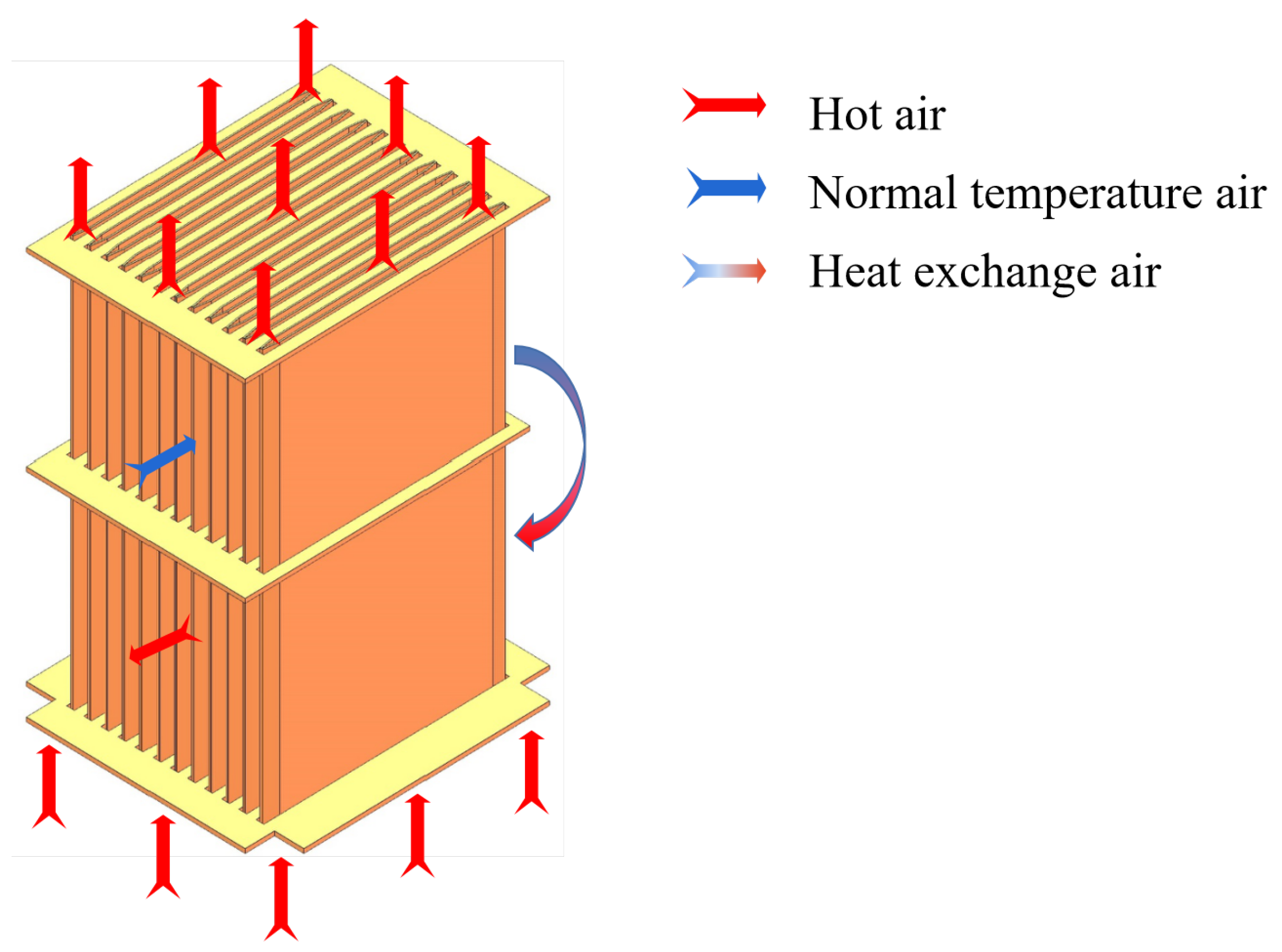
3.2. Anti-Pollution Plate Heat Exchanger

The heat exchange process uses a plate heat exchanger with hot and cold isolation. In this process, high-temperature gases produced by combustion pass through the interior of the heat exchanger plates. The plates heat up between their walls, conducting heat outward and exchanging heat with the air supplied by the blower outside the walls, thus completing the heat exchange process. The Plate heat exchanger cutaway view is shown in Figure 4.
The hot air furnace adopts a cross-flow heat exchange method, and the logarithmic mean temperature difference is calculated using the following formula:
Δ t = Δ t Δ t ln Δ t Δ t
where Δ t is the temperature difference between the hot and cold fluids at the inlet, Δ t = 800 − 200 = 600 °C; Δ t is the temperature difference between the hot and cold fluids at the outlet, Δ t = 100 − 25 = 75 °C. The logarithmic mean temperature difference is 252 °C.
The total heat exchange area of the heat exchanger can be calculated as
F = Q z P Δ t
where P is the heat transfer coefficient and, in this paper, the air-to-air heat transfer coefficient of 16 is used. Based on the above formula, the total heat exchange area of the heat exchanger should be 9.36 m2. Due to the limited volume of the furnace chamber, multiple plate heat exchangers are arranged inside it. In this device, 12 plates are used.

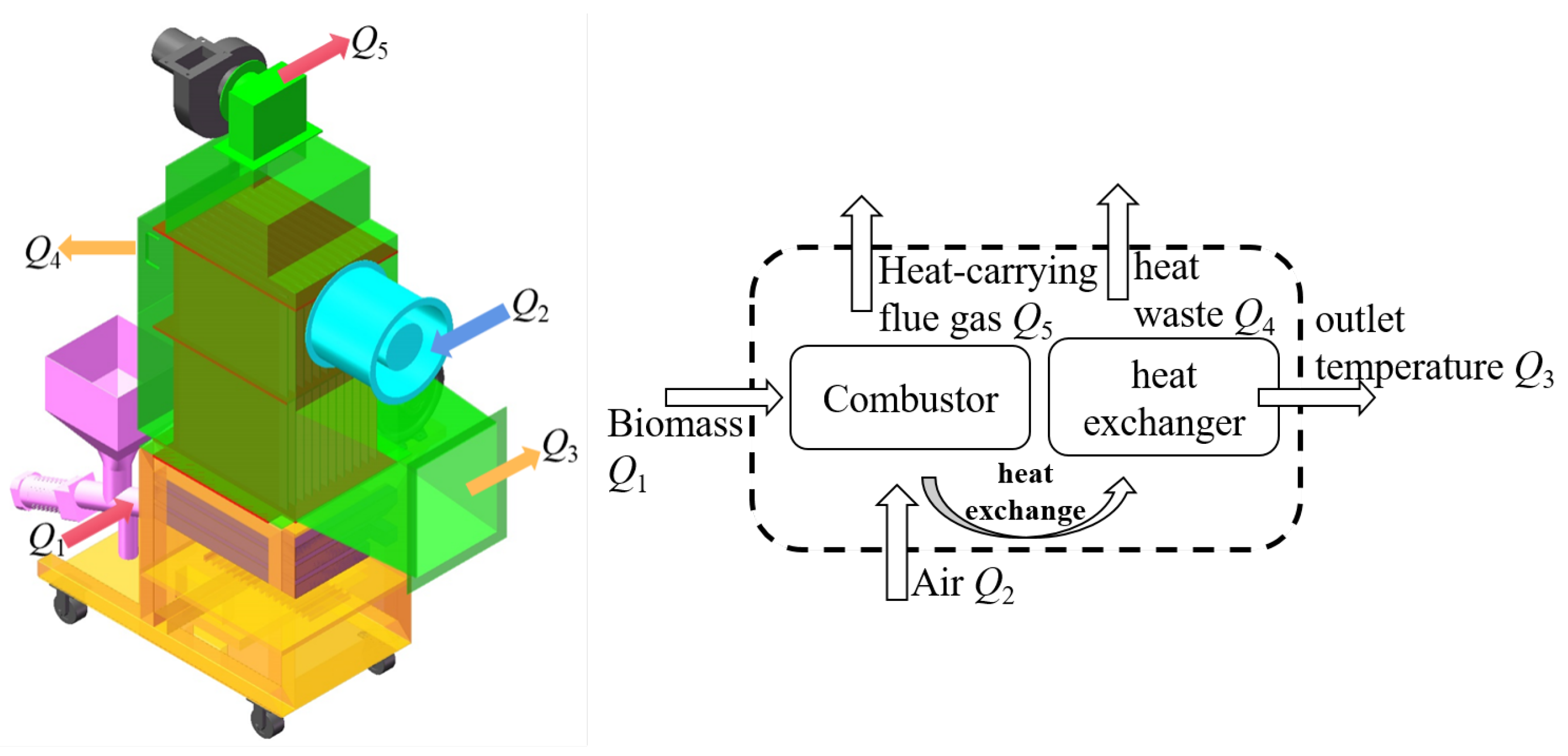
4. Temperature Model of the Biomass Hot Air Furnace

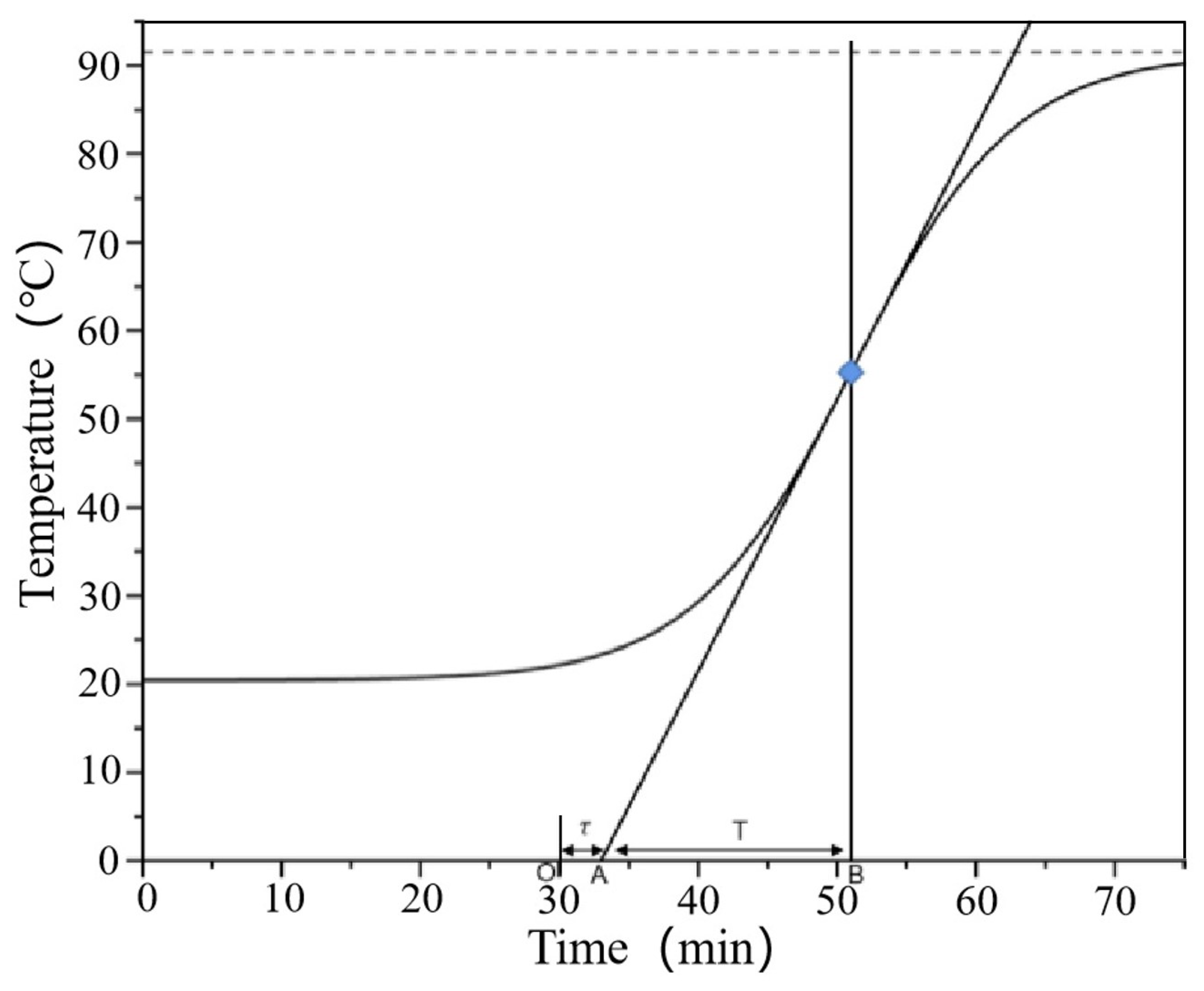
4.1. Derivation of the Biomass Hot Air Furnace Model

The biomass hot air furnace is considered as a whole system, assuming that the internal air is uniformly mixed [18]. The temperature at the outlet depends on the lower heating value of the biomass fuel and the feed rate, the heat exchange between the furnace body and the external environment, and the heat carried by the inlet air. According to the temperature set, if the actual outlet temperature is lower than the set temperature, the fuel delivery speed is increased to increase the input heat, and the inlet air quantity is appropriately reduced. Conversely, if higher, the fuel delivery speed is decreased, and the inlet air quantity is increased, to balance the outlet temperature with the set temperature. Let Q 1 be the heat generated by the combustion of biomass pellets per unit time, Q 2 be the heat of the air supplied by the blower, Q 3 be the heat of the air discharged from the outlet, Q 4 be the heat loss through the furnace walls, and Q 5 be the heat carried by the exhaust gases. The heat distribution of the hot air furnace is shown in Figure 5. The equation based on the dynamic heat balance model is as follows:
Q 1 + Q 2 = Q 3 + Q 4 + Q 5
The rate of change of temperature at the outlet can be expressed as
R C R L ρ c 0 t 1 β d t 1 d τ + t 1 = R L ρ c 0 t 0 + R Q 1 R L ρ c 0 t 1 β β R L ρ c 0 t 1 β t z
where L is the volume of air; ρ is the density of the air; C 0 is the specific heat of air; t 0 is the return air temperature (inlet temperature); t 1 is the outlet temperature; t z is the ambient air temperature; β is the heat transfer attenuation coefficient of the shell; R is the thermal resistance. Assuming T as the time constant R C / ( R L ρ c 0 t 1 β ) , K as the gain R L ρ c 0 / ( R L ρ c 0 t 0 β ) , and t f as the time delay ( R Q 1 β t z ) / ( R L ρ c 0 ) , Equation (9) can be expressed as
T d t 1 d t z + t 1 = K ( t 0 + t f )
Assuming initial conditions as zero and applying the Laplace transform, this equation becomes
G ( s ) = K T s + 1 e τ s
where K is the gain, indicating the ratio of the change in output to the change in input when the controlled system reaches a new equilibrium state. This is a constant not varying with time. The larger the K of a system under the same input conditions, the greater the output, meaning the input has a more significant impact on the output, and the stability of the controlled system is poorer. Conversely, the smaller the K, the better the stability of the system.
T is the time constant, indicating the speed at which the output reaches a new steady state after being subjected to an input, reflecting the rate of change over time in the entire dynamic process, a dynamic characteristic parameter of the controlled system.
τ is the time delay, reflecting the time taken for the controlled system to respond to an input and undergo change [19]. In this system, this is mainly determined by the volume of the hot air furnace and its heat exchange efficiency.

4.2. Establishment of the Biomass Hot Air Furnace Model

Through calculation and derivation, the temperature control system of the hot air furnace was identified as a first-order nonlinear system with a delay. To identify its parameters, the most commonly used experimental identification methods are the response curve method, correlation statistics method, and least squares method [13]. In this paper, the step response method from the response curve method was used to identify the relevant parameters.
First, the hot air furnace was maintained in a steady state at room temperature, and the input to the inverter was controlled to produce a step change [20]. The speed of the auxiliary combustion fan was increased to promote the combustion of biomass pellet fuel in the furnace, raising the temperature at the outlet until it reached a new steady state. During this period, a temperature sensor was used to record the temperature variation over time with a sampling period of 60 s; where t is the output, i.e., the outlet temperature, f0 is the frequency of the inverter under initial conditions, and f is the step change applied. The temperature variation curve over time is shown in Figure 6.
Using Origin’s curve fitting function, a polyline graph was fitted into a smoother step response curve that was easier to calculate, as shown in Figure 7. By analyzing the step response curve, the system parameters K, T, and τ were calculated. Consequently, the transfer function of the biomass hot air furnace’s temperature control system was determined based on these calculations.
G ( s ) = 3.08 889 s + 1 e 50 s

5. System Simulation of the Biomass Hot Air Furnace

5.1. Selection of the Simulation Controller

The traditional PID controller consists of three control units: proportional, integral, and derivative. The calculation formula is as follows:
u ( t ) = K p e ( t ) + K i e ( t ) d t + K d d e ( t ) d t
K p is the proportional coefficient, determining the sensitivity and stability of the control system. A higher K p value means smaller integral and derivative coefficients, enabling a quicker response to feedback. However, this may also lead to poor noise resistance, larger errors, and greater overshoot.
K I is the proportional-integral coefficient, which can improve the system’s tracking response performance, enhance noise resistance, and reduce output error. A smaller K I coefficient significantly enhances the system’s tracking performance but reduces its stability.
K D is the integral coefficient, suppressing errors and accelerating the response time. This constant is mainly used to improve a system’s dynamic quality, such as disturbance resistance and response speed, and can also enhance the ability to suppress errors [21].
Traditional PID control methods offer good adjustability and applicability. However, the temperature adjustment requirements for drying systems are high. Under different initial conditions, different hot air drying methods, and varying moisture content conditions, the temperature requirements for hot air drying vary as shown in Table 1 [22]. A high precision and extensive range adjustments are needed. Traditional PID controllers struggle to meet the temperature requirements under different conditions, leading to large overshoots, long adjustment times, and consequently poor control effects and drying results falling short of expectations.
Fuzzy logic theory, however, can effectively solve these problems. Fuzzy logic control methods are based on a large amount of process data, primarily relying on human-like fuzzy "if-then" rules. These rules are expressed in simple language and combined with traditional non-fuzzy processing. The results of all individual rules are then averaged into a defuzzified signal, guiding the controller’s actions [23]. It adjusts its control parameters automatically in real time based on the process’s current state and performance. This adaptability is crucial for dealing with the nonlinear and time-varying behaviors of many systems, ensuring optimal performance under varying operating conditions. By integrating fuzzy logic with PID control, the system can handle uncertainty and imprecision more effectively than traditional PID controllers. By optimizing the combustion process and maintaining precise temperature control, this system can improve the overall energy efficiency of a biomass hot air furnace.

5.2. Basic Principles of the Fuzzy PID Controller

A fuzzy controller primarily consists of three modules: fuzzification, fuzzy inference, and defuzzification.
Fuzzification: This involves establishing the domain of fuzzy sets and determining the range of variation for input and output variables in practical work. Inputs and outputs are quantified by multiplying them with a quantification factor in their respective domains, converting them to a common domain. Membership functions are then defined for each fuzzy subset that requires fuzzification, ultimately achieving fuzzification of the controller variables [24].
Fuzzy inference: When the system operates in different states, the input value deviation e and the rate of change of the input value deviation e c are calculated based on the measured actual values. The values of e and e c vary within a certain range, which is divided into seven parts, represented as P B , P M , P S , Z O , N S , N M , N B and corresponding to “positive big, positive medium, positive small, zero, negative small, negative medium, negative big”, respectively. The output increments Δ K p , Δ K I , Δ K D also undergo the same fuzzification process as e and e c [25]. Based on past control experience and the quantification of inputs and outputs, the system’s state and trend are determined. The rules for Δ K p , Δ K I , Δ K D in adaptive fuzzy PID control are established based on different combinations of variables e and e c .
Defuzzification: This process converts the fuzzy quantities in fuzzy inference into clear quantities used for control. First, the fuzzy control quantities are transformed into clear quantities in the domain. Then, these clear quantities within the domain range are converted into control quantities [26].

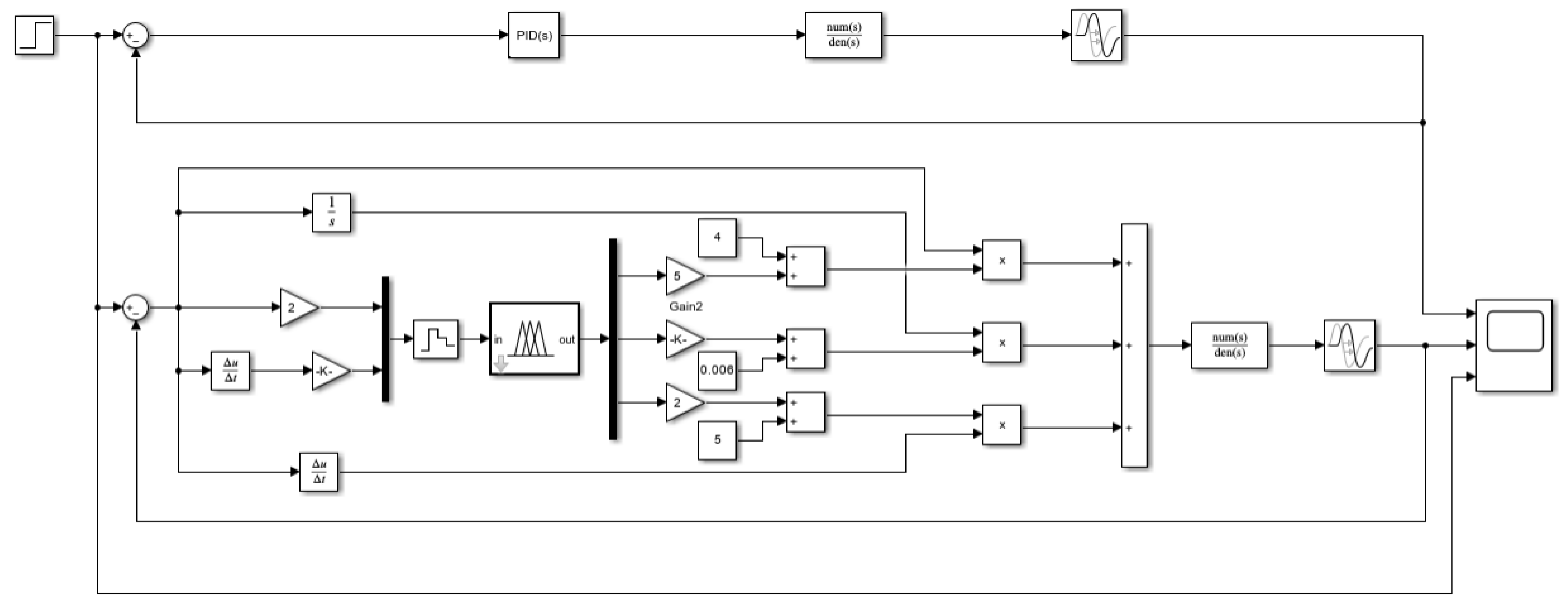
5.3. Design of the Fuzzy PID Controller

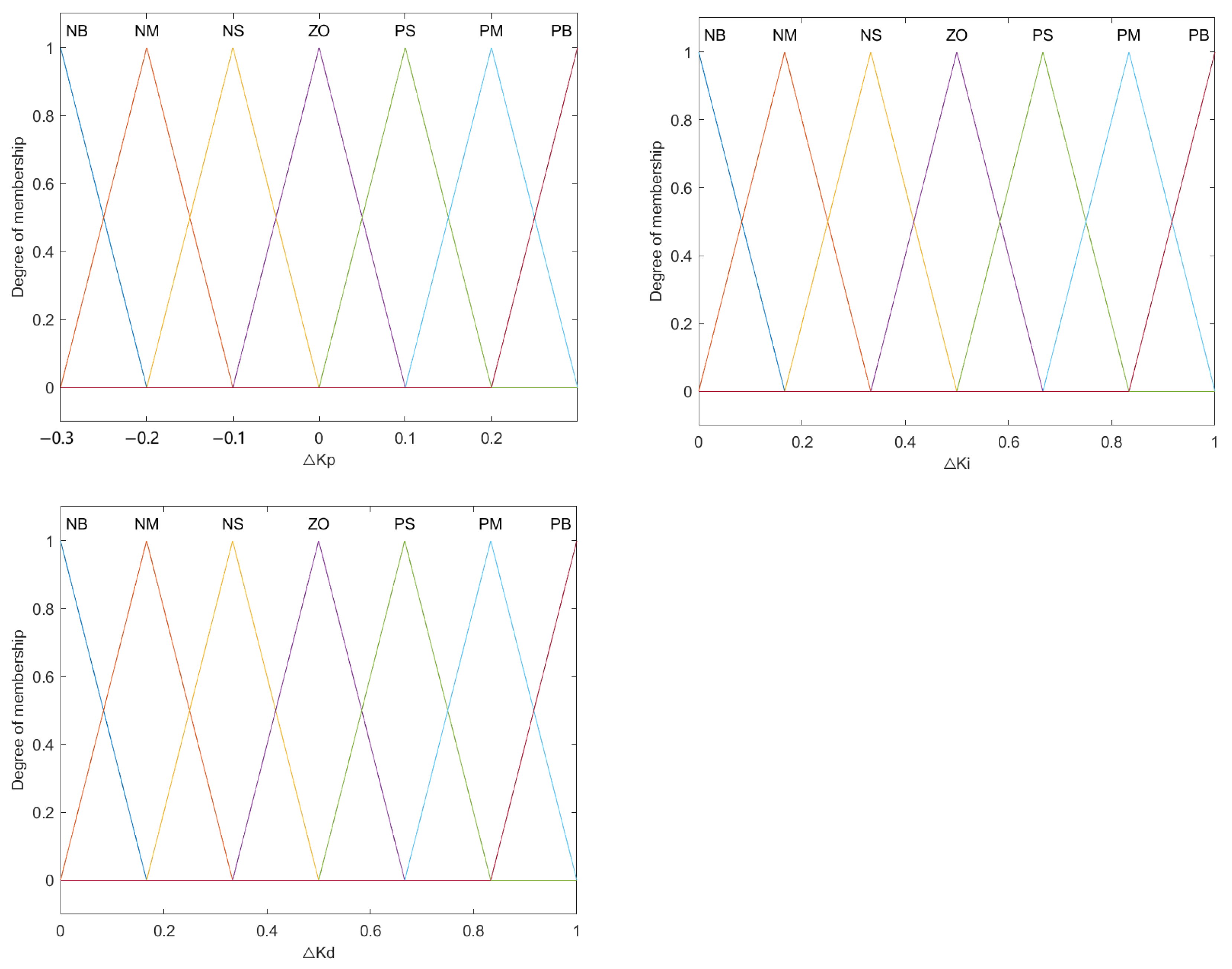
5.3.1. Fuzzification

The temperature control system of the biomass hot air furnace adopts a two-input, three-output structure. The input language of the fuzzy controller is the temperature difference, denoted as e, set within the range of [−3, 3]. It is divided according to intervals, with the rate of change of the temperature difference denoted as e c , and the sampling period Ts set at 60 s, having a domain of [−3, 3]. The output languages are Δ K p , Δ K I , Δ K D , with the fuzzy domain chosen as [−3, −2, −1, 0, 1, 2, 3]. The domain for Δ K p is [−0.3, 0.3], for Δ K I it is [0, 1], and for Δ K D it is [0, 1]. The quantification factors for the controller outputs are as follows, with Δ K p , Δ K I , Δ K D , all using Z-type membership functions. The membership functions are shown in Figure 8.

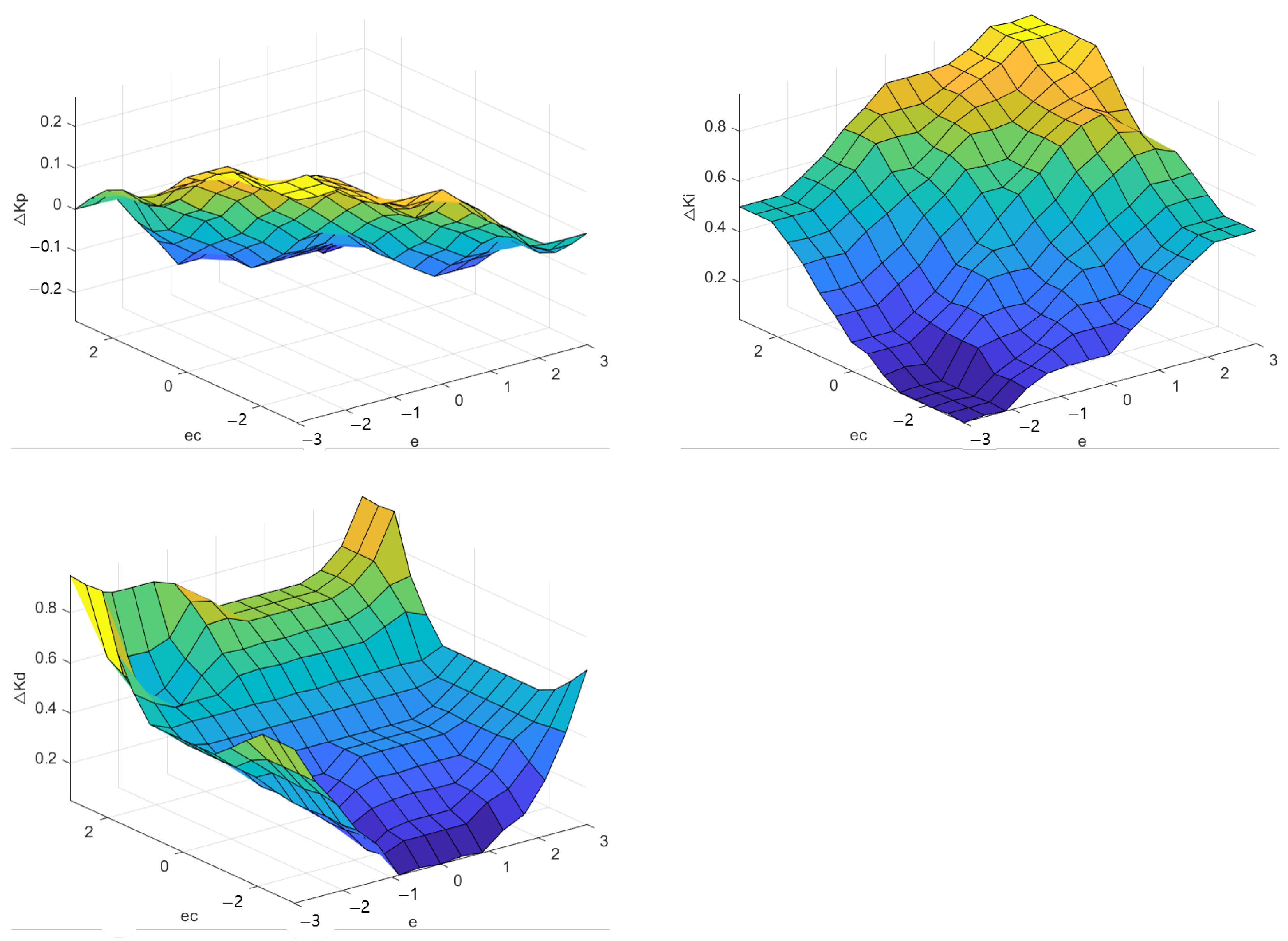
5.3.2. Fuzzy Inference

Based on the temperature variation pattern of the biomass hot air furnace’s temperature control system and the roles of Δ K p , Δ K I , and Δ K D in PID control, the following fuzzy control rules were established:
1.
During system startup or shutdown, when there is a significant difference between the set temperature and the actual temperature, a larger Δ K p should be chosen to increase the response speed. To avoid excessive deviation e at the beginning, causing differential saturation and pushing the control beyond permissible limits, a moderate Δ K D should be chosen. To prevent overshoot and integral saturation at startup, a smaller or elimination of the integral action Δ K I = 0 is preferable.
2.
Once the system is operating normally, with moderate temperature deviation e and rate of temperature deviation change e c , a smaller Δ K p should be selected to minimize overshoot. The values of Δ K I and Δ K D should be moderate to maintain the system’s response speed.
3.
When the system’s temperature is nearly stable, with a small temperature deviation e, Δ K p and Δ K I can be moderately increased to enhance system stability, while Δ K D should be adjusted to avoid oscillation near the setpoint and to consider the system’s disturbance rejection capability. A higher Δ K D value should be used when e c is small, and a lower Δ K D value when e c is large [27].
The fuzzy control rules based on these principles are specified in Table 2. The surface of the fuzzy control rules is shown in Figure 9.

5.3.3. Defuzzification

Defuzzification involves calculating the output value in the domain based on the membership degrees obtained from fuzzy inference and then determining the output using interval mapping relationships. Common methods for defuzzification include the mean of maximum method, the maximal membership principle, and the center of area method [28]. This paper adopted the center of area method, to obtain precise output values, as shown in Equation (14). In the actual control process, the calculated results are stored in the processor as a control decision table. During control, corresponding values are queried to read data, reducing the computation time and improving the response speed.
Z 0 = i = 0 n μ c ( Z i ) Z i i = 0 n μ c ( Z i )
where Z 0 is the precise value after defuzzification of the fuzzy controller; Z i are the values within the domain of the fuzzy control quantity; and μ c ( Z i ) is the membership degree of Z i .
The traditional Ziegler–Nichols tuning formula, after being modified, appears in various designs of PID controllers. The Cohen–Coon method is one such calculation and similar to Ziegler–Nichols [29]. The calculation method is shown in Table 3.
Among them a = K τ T , L = τ T + τ , where Δ K p , Δ K I , Δ K D are the initial values from Table 3, which can be determined using model parameters and Table 2. During the machine’s operation, real-time deviations and rates of change in the deviation are collected and calculated. By consulting the fuzzy control rule table, corresponding adjustment values are obtained, thereby adjusting the three parameters of the fuzzy PID controller, and in turn fine-tuning the controller parameters [30,31].

6. Simulation and Testing of Biomass Hot Air Furnace Temperature Control System with Simulated PID

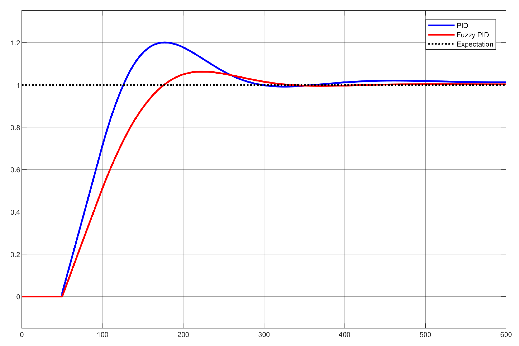
6.1. Simulation Test

To validate the adjustment performance of the adaptive fuzzy PID temperature control system, a simulation model based on Simulink in Matlab was constructed.During the simulation process, the control coefficient was set to 1.0, and a ramp function with a slope of −0.17 was added to simulate the temperature curve changing over time. The performances of conventional PID and fuzzy PID were compared by running simulations and analyzing their behaviors. The structure of the simulation is shown in Figure 10. The simulation results are shown in Table 4.
(1) Figure 11 shows the response of the biomass hot air furnace temperature control system to a set signal of 1.0. The settling times for PID and fuzzy PID were 445 s and 364 s, respectively, with overshoots of 20.1% and 6.3%, respectively.The fuzzy PID temperature control, compared to the conventional PID control, demonstrated a smaller overshoot, shorter adjustment time, and smaller error. It exhibited better dynamic response characteristics and steady-state performance, achieving effective control.
(2) Figure 12 illustrates the temperature control performance of the system set at a temperature of 100 °C. The error with fuzzy PID was smaller, showing a higher fitting with the set temperature and better temperature tracking performance, meeting the design requirements.

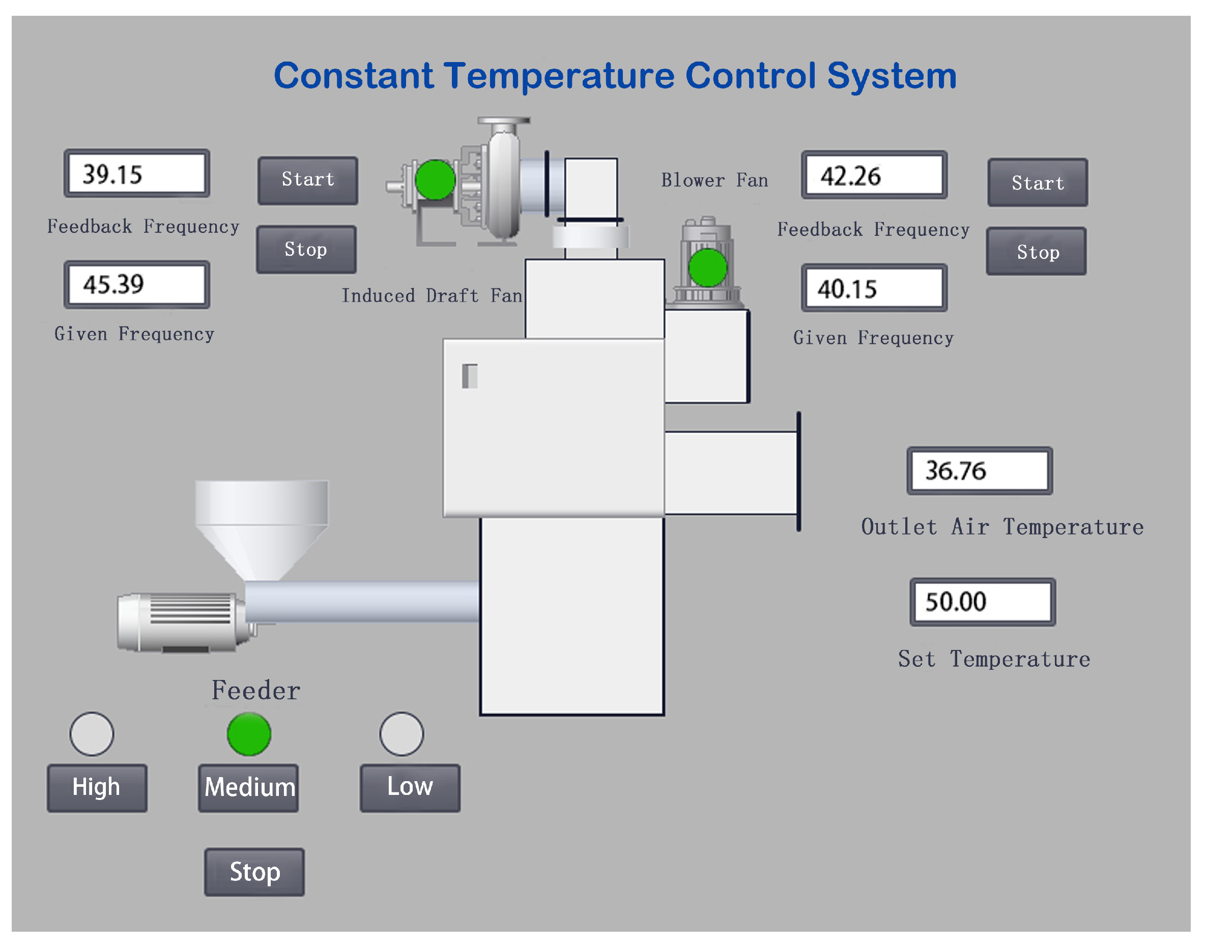
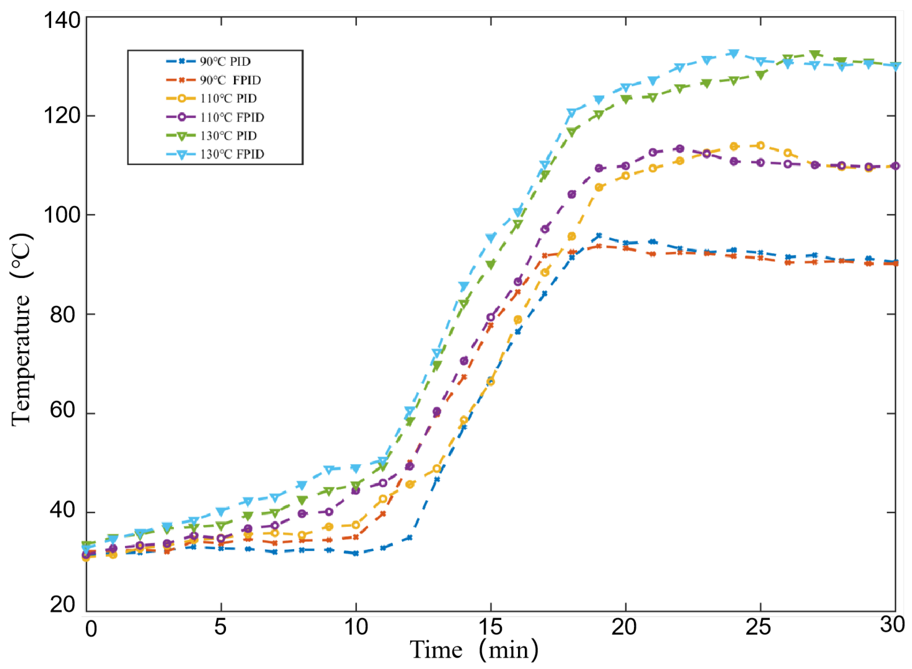
6.2. Experimental Testing

To validate the feasibility and superiority of the fuzzy PID temperature control system, comparative experiments were conducted using two different algorithms under the same environmental temperature conditions. The physical picture of the biomass hot air furnace is shown in Figure 13, and its human-computer interaction interface is shown in Figure 14. The experiments utilized a biomass hot air furnace developed in collaboration with a biomass energy equipment company. The average temperature at the outlet was calculated using 4 PT100 thermocouples. The outlet area was 0.18 m2, and the inlet area was 0.13 m2. Control was achieved using an EV4300 type variable frequency drive, with a controllable frequency range of 0–50 Hz. The environmental temperature was 31 °C, and the humidity was 40%. The target temperatures were set at 90 °C, 110 °C, and 130 °C, with the temperature trends over time recorded every minute for different controllers, as shown in Figure 15. The temperature performance parameters of PID and Fuzzy PID are shown in Table 5.
The drying temperature experiments showed that using adaptive fuzzy PID control at 90 °C and 110 °C, the temperature control precision reached ±5 °C, and the time was consistently controlled within 1300 s, demonstrating a better temperature control performance compared to traditional manual control and classic PID control. At 130 °C, due to higher temperature requirements, the response time was longer, but the temperature control precision was higher with smaller errors.
Under the regulation of adaptive fuzzy PID, the temperature variation was within a reasonable range, meeting the drying requirements for rapeseed. There was no overshoot, and the curve was almost smooth, indicating that the temperature control was overall stable. Through a comparative analysis of the simulation tests and experiments, it was demonstrated that the improvements based on adaptive fuzzy PID effectively enhanced the precision of temperature control. This provides robust support for the design and improvement of control systems for biomass hot blast furnaces.

7. Conclusions

Through an understanding of the working principles of drying equipment and the temperature requirements during the rapeseed drying process, this study focused on a biomass hot air furnace and established a temperature model based on fuzzy PID control. The aim was to complete the rapeseed drying process in an economical and effective manner. The use of biomass for combustion not only reduces energy consumption but also lowers emissions.
1.
This paper presents a structural design for a multi-channel circulating biomass hot air furnace. The prototype developed offers energy efficiency and thorough combustion, meeting the technological requirements for drying agricultural products. This provides a theoretical basis for the structural and performance design of drying systems for related agricultural products;
2.
Using automatic control theory and experimental data, a mathematical model of the biomass hot air furnace was derived. Considering the nonlinearity and long time-delay characteristics of the combustion furnace, advanced computer simulations were conducted under different operating conditions. It was found that adopting a fuzzy PID control strategy could effectively regulate the temperature of the biomass hot air furnace;
3.
Compared to a traditional uncontrollable controller, the fuzzy PID controller could adaptively adjust the PID parameters based on the system’s real-time feedback and a predefined rule base, to accommodate the dynamic changes during the operation of biomass hot air furnaces.The operational characteristics of biomass hot air furnaces exhibit significant non-linearity, which traditional PID control may not flexibly manage. By incorporating fuzzy logic, fuzzy PID control can better handle such non-linearity, enhancing the system’s response speed and stability. Fuzzy PID control can effectively minimize the phenomena of overshoot and oscillations when the system reaches set temperatures or other operational parameters, ensuring smoother and more reliable furnace operation.
In future research and practical applications. We look forward to conducting research on biomass combustion technology from the following perspectives: (1) Fuel diversity and adaptability: To explore the combustion performance of different types of fuels in hot air furnaces, assessing their impact on thermal efficiency, sustainability, and cost-effectiveness. (2) Environmental impact assessment: To conduct more in-depth studies to evaluate the environmental impact of operating biomass hot air furnaces, including a detailed analysis of the types and quantities of emissions. (3) Economic analysis: To perform comprehensive economic analyses of biomass hot air furnaces, considering cost–benefit ratios, operational costs, and maintenance expenses.

Author Contributions

Conceptualization, H.L. and M.W.; Methodology, H.L.; Software, T.S.; Validation, T.S., H.L. and M.W.; Formal analysis, H.L.; investigation, T.S.; resources, H.L.; Data curation, T.S.; Writing—original draft preparation, T.S.; Writing—review and editing, T.S.; Visualization, T.S.; Supervision, M.W.; Project administration, M.W.; Funding acquisition, M.W. All authors have read and agreed to the published version of the manuscript.

Funding

This research was funded by the National Key R&D Program (2022YFD2300103), Research on Research and development of key technologies for light and simplified high-yield rapeseed.

Institutional Review Board Statement

Not applicable.

Data Availability Statement

All data are presented in this article in the form of figures and tables.

Conflicts of Interest

The authors declare no conflicts of interest.

References

  1. Huo, L.; Zhao, L.; Yao, Z.; Luo, J.; Zhang, P.; Xie, T.; Wei, X. Potentiality of agricultural biomass energy for greenhouse gas emission reduction. Trans. Chin. Soc. Agric. Eng. 2021, 37, 179–187. [Google Scholar]
  2. Fupeng, S. Research on Biomass Pellet Air-heating Furnace Technology in the Field of Grain Drying. Ind. Heat. 2022, 51, 20–23. [Google Scholar]
  3. Ruixia, S.; Zonglu, Y.; Lixin, Z. Rural Living Energy in Heilongjiang Province under Background of Carbon Peak and Neutrality. Trans. Chin. Soc. Agric. Mach. 2022, 53, 377–383. [Google Scholar]
  4. Gang, C. Typical Agricultural Product Drying Technology and Intelligent Equipment; Chemical Industry Press: Amersham, UK, 2017. [Google Scholar]
  5. Yan, P.; Xiao, C.; Xu, L.; Yu, G.; Li, A.; Piao, S.; He, N. Biomass energy in China’s terrestrial ecosystems: Insights into the nation’s sustainable energy supply. Renew. Sustain. Energy Rev. 2020, 127, 109857. [Google Scholar] [CrossRef]
  6. Jiao, X. Study on Fuzzy PID Control System of Temperature for Air Heated Furnace of Forage Dryer; Northeast Agricultural University: Harbin, China, 2011. [Google Scholar]
  7. Jun, H. Design and Research of Small Biomass Shaped Fuel Burner; Central South University of Forestry and Technology: Changsha, China, 2021. [Google Scholar]
  8. Lei, Y. Design and Application Reaearch of Fuel Stove for Straw Forming. Transactions of the Chinese Society for Agricultural Machinery: 1–9. Available online: http://kns.cnki.net/kcms/detail/11.1964.S.20230914.1030.007.html (accessed on 10 December 2023).
  9. Bin, L.; XiaoFeng, Y.; ZhuYu, D.; Lin, Y.; MingJin, Y. On Fuzzy PID to Control System of Rapeseed Hot Air Drying. J. Southwest China Norm. Univ. Sci. Ed. 2016, 41, 109–114. [Google Scholar]
  10. Smith, J.D.; Sreedharan, V.; Landon, M.; Smith, Z.P. Advanced Design Optimization of Combustion Equipment for Biomass Combustion. Renewableenergy 2019, 145, 1597–1607. [Google Scholar] [CrossRef]
  11. Junior, M.P.; da Silva, M.T.; Guimaraes, F.G.; Euzebio, T.A.M. Energy savings in a rotary dryer due to a fuzzy multivariable control application. Dry. Technol. 2022, 40, 1196–1209. [Google Scholar] [CrossRef]
  12. Bhler, L.; Krail, J.; Grtler, G.; Kozek, M. Fuzzy model predictive control for small-scale biomass combustion furnaces. Appl. Energy 2020, 276, 115339. [Google Scholar] [CrossRef]
  13. Zhang, X.; Zhang, Y.; Yao, Z.; Zhao, Y.L.; Meng, H.; Tian, Y. Effect of burners with different feeding modes on emission characteristics of biomass molding fuel particles. Trans. Chin. Soc. Agric. Eng. 2014, 30, 200–207. [Google Scholar]
  14. Liu, L.; Zhao, J.; Wang, D. Design and experiment of a heating boiler using straw briquette as fuel. Trans. Chin. Soc. Agric. Eng. 2022, 38, 230–236. [Google Scholar]
  15. Yang, G.; Yu, Y.F.; Sheng, K. Effect of feeding rate on pollutant emission of biomass pellet burner. J. Zhejiang Univ. Life Sci. 2017, 43, 390–396. [Google Scholar]
  16. Liu, S.; Wang, S.; Li, Y.; Yaya, L.; Yuanshuai, L. Design and Combustion Characteristics Experiment of Biomass Crushed Aggregates Burner for Anti-tempering Maize Straw and Wood Chips. Trans. Chin. Soc. Agric. Mach. 2020, 51, 346–354. [Google Scholar]
  17. Duo, H. Design and Test of Biomass Fuel Combustion Furnace; Kunming University of Science and Technology: Kunming, China, 2019. [Google Scholar]
  18. Wu, X.F.; Li, D.M. Modeling of Climatic Environment Test Facility and Temperature Control System Simulation. Meas. Control Technol. 2015, 34, 63–66. [Google Scholar]
  19. Wang, X.C. Design and Research of Fuzzy Parameter-Adaptive PID Temperature Control System; Central South University: Changsha, China, 2007. [Google Scholar]
  20. Pang, Z. System Identification and Adaptive Control MATLAB Simulation; Beijing University of Aeronautics and Astronautics Press: Beijing, China, 2022. [Google Scholar]
  21. Huang, L. Research on Fuzzy Control in Hot-Blast Stove Temperature Control System; Changchun University of Science and Technology: Changchun, China, 2010. [Google Scholar]
  22. NY/T 1087-2006; Technical Regulations for Drying and Storage of Rapeseed. Ministry of Agriculture of the PRC: Beijing, China, 2006.
  23. Dufour, P. Control Engineering in Drying Technology: Review and Trends. Dry. Technol. 2006, 24, 889–904. [Google Scholar] [CrossRef]
  24. Li, X.; Xu, B.; Yuan, Y. Research on temperature control system of piglet bed based on adaptive fuzzy PID algorithm. J. Chin. Agric. Mech. 2020, 41, 48–53. [Google Scholar]
  25. He, G.; Cai, X.; Bai, Y.; Zhu, L.; Wang, D.; Hou, Y. Design and Test of Temperature Control System of Calf Milk Replacer Solution Based on Fuzzy PID. Trans. Chin. Soc. Agric. Mach. 2022, 53, 266–276. [Google Scholar]
  26. Rongyu, H.E. Electrothermal Furnace’s Intelligent Temperature Control System Based on Fuzzy PID; Hunan University: Changsha, China, 2014. [Google Scholar]
  27. Wang, S.; Shi, Y.; Feng, Z.X. A Method for controlling a Loading System based on a Fuzzy PID Controller. Mech. Sci. Technol. Aerosp. Eng. 2011, 30, 166–172. [Google Scholar]
  28. Muqing, D. Optimization Design Of Thermostat Temperature Controller Based on Predictive Controll And Fuzzy PID Controll; Central South University of Forestry and Technology: Changsha, China, 2022. [Google Scholar]
  29. Defeng, Z. MATLAB Control System Design and Simulation; Publishing House of Electronics Industry: Beijing, China, 2009. [Google Scholar]
  30. Yuan, N.Z.; Zhi, L.X.; Yun, L.H.; Geng, Z. Application of self-tuning PID-Fuzzy controller in furnace temperature control. Autom. Instrum. 1996, 5, 30–34. [Google Scholar]
  31. Jinkun, L. Advanced PID Control MATLAB Simulation; Publishing House of Electronics Industry: Beijing, China, 2016. [Google Scholar]
Figure 1. Three-dimensional diagram of the hot air furnace. 1. feed motor; 2. hopper; 3. combustion chamber; 4. auxiliary combustion fan; 5. outlet; 6. blower (inlet); 7. heat exchange chamber; 8. induced draft fan; 9. outlet; 10. plate heat exchanger.
Agriculture 14 00419 g001
Figure 2. Working principle diagram of the biomass hot air furnace.
Agriculture 14 00419 g002
Figure 3. (A) Embedded combustion-supporting air duct, (B) wind direction diagram of the inner wall pipe of the hot air furnace.
Agriculture 14 00419 g003
Figure 4. Plate heat exchanger cutaway view.
Agriculture 14 00419 g004
Figure 5. Heat Distribution diagram of the hot air furnace.
Agriculture 14 00419 g005
Figure 6. Temperature variation curve of the biomass hot air furnace.
Agriculture 14 00419 g006
Figure 7. Step response curve of the open-loop temperature control system.
Agriculture 14 00419 g007
Figure 8. Membership function of Δ K p , Δ K I , Δ K D .
Agriculture 14 00419 g008
Figure 9. Surface of fuzzy control rules.
Agriculture 14 00419 g009
Figure 10. Simulation structure based on Simulink.
Agriculture 14 00419 g010
Figure 11. Comparison of response curves between conventional PID and fuzzy PID.
Agriculture 14 00419 g011
Figure 12. Temperature change output response curve.
Agriculture 14 00419 g012
Figure 13. Physical picture of the biomass hot air furnace.
Agriculture 14 00419 g013
Figure 14. Human–computer interaction interface.
Agriculture 14 00419 g014
Figure 15. Temperature time trend chart.
Agriculture 14 00419 g015
Table 1. Temperature requirements of hot air drying under different moisture content conditions.
Initial Water Content of RapeseedMixed-Flow DryingDrum DryingFluid Bed Drying
18 % 9011090
12–18%110130120
12 % 130150140
Table 2. Table of fuzzy control rules.
e c e NBNMNSZOPSPMPB
NBPB/NB/PSPB/NB/PSPB/NB/ZOPM/NM/ZOPS/NS/ZOPS/ZO/PBZO/ZO/PB
NMPB/NB/NSPB/NB/NSPM/NB/NSPM/NM/NSPS/NS/NSZO/ZO/NSZO/ZO/PM
NSPM/NM/NBPM/NM/NBPM/NS/NMPS/NS/NSZO/ZO/PSNS/PS/PMNM/PS/PM
ZOPM/NM/NBPS/NS/NMPS/NS/NSZO/ZO/NSNS/PS/PMNM/PS/PSNM/PM/PS
PSNB/PS/NBPS/NS/NBZO/ZO/NSPS/NS/PSNS/NS/PBNM/PS/PMNM/PM/PS
PMZO/ZO/NMZO/ZO/NMNS/PS/NSNM/PM/NSNM/PM/ZONM/PB/PSNB/PB/PS
PBZO/ZO/PSNS/ZO/ZONM/PS/ZONB/PB/ZONB/PB/PBNB/PB/PSNB/PB/PS
Table 3. Cohen–Coon tuning method for different controllers.
K p K i K d
P 1 a 1 + 0.35 τ r 1 τ r //
PI 0.9 a 1 + 0.92 τ r 1 τ r 3.3 3 τ r L 1 + 1 1.2 τ r /
PD 1.24 a 1 + 0.13 τ r 1 τ u / 0.27 0.36 τ r L 1 0.87 τ r 1 0.87 τ r
PID 1.35 a 1 + 0.18 τ r 1 τ r 2.5 2 τ r L 1 0.39 τ r 1 0.39 τ r 0.37 0.37 τ r L 1 0.81 τ r 1 0.81 τ r
Table 4. Performance comparison of different control methods.
Control ModeStabilization Time (s)Steady State ErrorOvershoot (%)
PID4450.01920.1
Fuzzy PID3640.0116.3
Table 5. The temperature performance parameters of PID and Fuzzy PID.
Sequence NumberControl ModeTemperature Setting (°C)Stabilization TimeSteady State ErrorOvershoot (%)
1PID9010685.86.4
2Fuzzy PID9010143.74.1
3PID11012904.03.6
4Fuzzy PID11012073.43.1
5PID13017042.51.9
6Fuzzy PID13015062.72.0
Disclaimer/Publisher’s Note: The statements, opinions and data contained in all publications are solely those of the individual author(s) and contributor(s) and not of MDPI and/or the editor(s). MDPI and/or the editor(s) disclaim responsibility for any injury to people or property resulting from any ideas, methods, instructions or products referred to in the content.

