Article

Design of a New Drip Irrigation Belt Recovery Machine with Anti Breakage Function

1
College of Mechanical and Electronic Engineering, Tarim University, Alar 843300, China
2
Xinjiang Production and Construction Corps Key Laboratory of Utilization and Equipment of Special Agricultural and Forestry Products in Southern Xinjiang, Alar 843300, China
*
Author to whom correspondence should be addressed.
Agriculture 2024, 14(3), 421; https://doi.org/10.3390/agriculture14030421
Submission received: 27 January 2024 / Revised: 28 February 2024 / Accepted: 29 February 2024 / Published: 5 March 2024
(This article belongs to the Section Agricultural Technology)

Abstract

:
Drip irrigation technology is widely used in agricultural production in the Xinjiang region. However, there are still a series of problems in the mechanized recovery of field drip irrigation belts, such as easy breakage of drip irrigation belts, low recovery efficiency, and excessive doping of recycled drip irrigation belts. This study focused on the problems of mechanized recovery of drip irrigation belts in Xinjiang and designed a new type of drip irrigation belt recovery machine. The key mechanisms of the new drip irrigation belt recovery machine were designed and theoretically analyzed, and their basic parameters were determined. Then, the superiority of the new drip irrigation belt recovery machine’s operational performance was verified through experiments. The experimental results showed that the new drip irrigation belt recovery machine is superior to existing machines in terms of the drip irrigation belt recovery rate and operational efficiency. In addition, the drip irrigation belts recovered by the newly designed machine have low impurity content. During the recovery process, the new machine requires less labor input than that of the existing machine.

1. Introduction

Drip irrigation technology plays an important role in improving agricultural water efficiency and farmer benefits [1,2,3], as well as protecting the ecological environment [4,5,6]. This technology has been widely applied in agricultural irrigation operations in Xinjiang [7], which has led to an increasing use of drip irrigation belts [8,9]. However, determining how to mechanically and efficiently recover a large amount of discarded drip irrigation belts in farmland is still a problem that needs to be solved. At present, most of the drip irrigation belts used in China are disposable. Its price is low, and it is highly accepted by farmers. However, its mechanical properties will show a significant decrease after one year of use [10]. In addition, after the crops are harvested, there are many pieces of straw and weeds, plastic film, and soil blocks in the field. Therefore, there are common problems in the mechanized recovery of drip irrigation belts in the field, such as easy breakage of drip irrigation belts, low recovery efficiency, and high impurity content in the recovered drip irrigation belts. Furthermore, the drip irrigation belts left in the field after rupture not only hinder the normal growth of crops but also become a source of soil pollutants.
Regarding the research on drip irrigation belt recovery machines, due to the fact that drip irrigation belts in foreign countries mainly use high-strength drip irrigation belts that can be recycled multiple times [11,12], the problem of mechanized field recovery of drip irrigation belts is not prominent [13]. In China, due to the prominent issues in this area, the relevant research literature has introduced some methods and results of drip irrigation belt recovery. Ding Shuangshuang [14] and Gong Hehe [15] respectively designed 4HS and 4HR drip irrigation belt recovery machines. The basic principles of these two machines are similar, and they can lift, transport, and collect drip irrigation belts from the ground in one go. This type of equipment can automatically lift drip irrigation belts, but the machine efficiency is not high and the structure is not compact. Tang Aimin [16] designed the 2JMSD-4.5 film stripping and drip irrigation belt recovery machine. This machine can be used for plastic film recovery in spring and drip irrigation belt recovery in autumn, achieving multiple uses for one machine. However, none of the above studies have addressed the issue of drip irrigation belts being prone to breakage under shallow burial and obstacles from agricultural materials.
In the field, especially in cotton fields, drip irrigation belt recovery is carried out after cotton picking and before the cotton stalks are crushed and returned to the field [17,18,19]. In addition, during the recovery period, drip irrigation belts are generally shallowly buried in the soil [20,21]. In addition, there is a 0.015 mm thick plastic film on the drip irrigation belts, surrounded by various weeds [22,23]. So, drip irrigation belts usually bear significant resistance during the recovery process, which is also one of the important reasons why drip irrigation belts are prone to breakage [24,25]. In addition, although the initial speed of the winding mechanism of the existing drip irrigation belt recovery machine is synchronized with the machine’s motion speed, the turning radius of the winding mechanism increases with the increase in the number of drip irrigation belt entanglements. This leads to a continuous increase in the linear speed of the winding mechanism, so its winding speed will eventually be greater than the machine’s forward speed. At this point, the drip irrigation belt will be pulled and slid relative to the ground, causing the drip irrigation belt to withstand significant resistance. This is a prominent technical problem that currently exists in the operation of drip irrigation belt recovery machines. In addition, manual intervention is required to unload the recovered drip irrigation belts from the winding mechanism, which is time-consuming and laborious work.
In this study, a new design scheme for a drip irrigation belt recovery machine was proposed to address the many shortcomings of existing ones. Firstly, in response to the problem of easy breakage of drip irrigation belts during the mechanized recovery process, a beating mechanism was designed, which can shake off various debris entangled on the drip irrigation belts and reduce the resistance when stretching the drip irrigation belts. Secondly, a winding mechanism with torque limitation and a hydraulic-assisted unloading function was designed. When the winding mechanism operates, if its torque exceeds the set value, it begins to slow down, meaning its movement speed is always synchronized with the machine’s forward speed. Finally, in order to verify the superiority of the newly designed drip irrigation belt recovery machine in terms of operational performance, comprehensive experiments were conducted on the newly designed machine and existing commonly used machines to compare their field performance indicators.

2. Materials and Methods

2.1. Structure and Working Principle

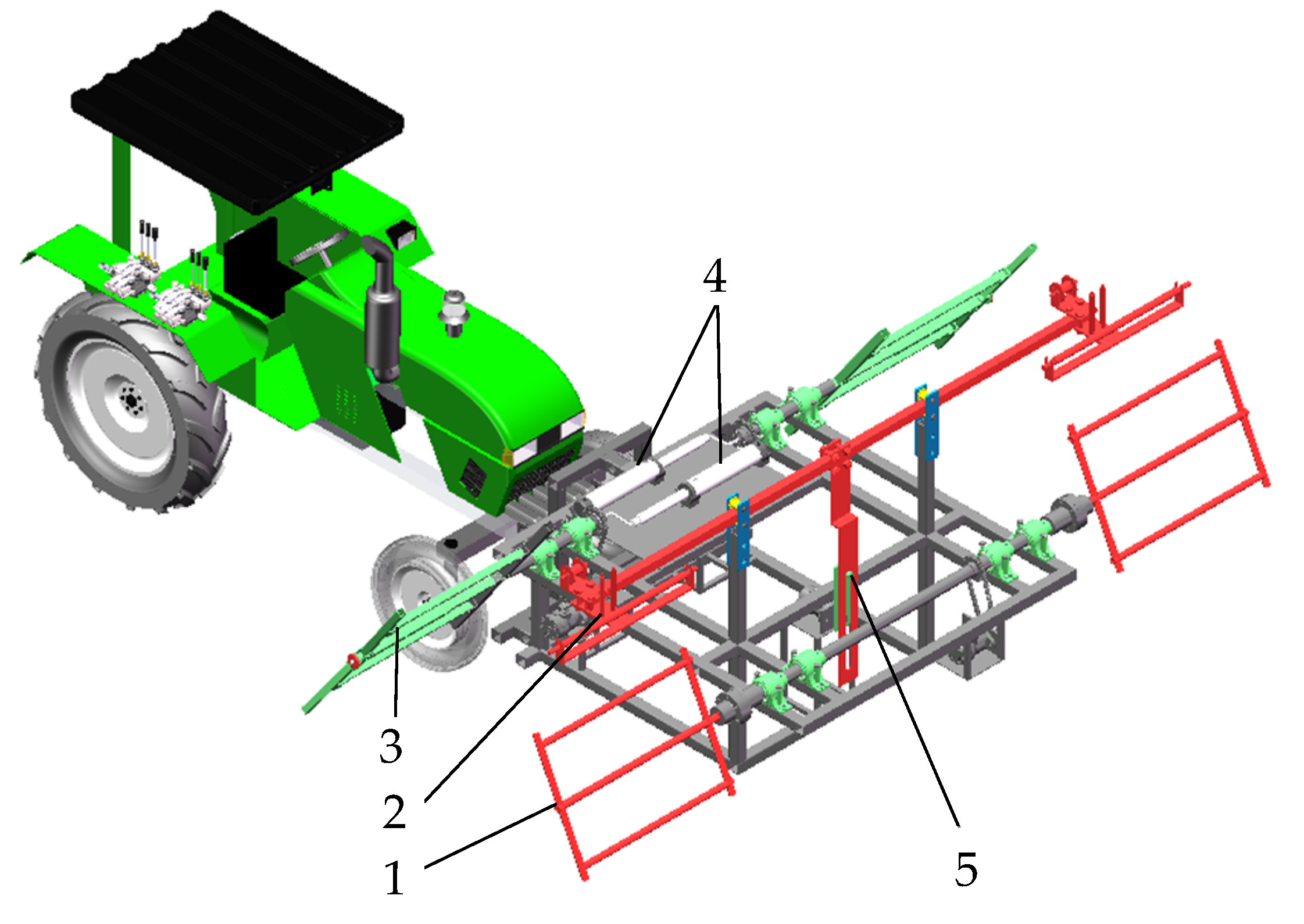
2.1.1. Structure of Drip Irrigation Belt Recovery Machine

The structure of the new drip irrigation belt recovery machine is shown in Figure 1. For the convenience of the driver to better observe the operation of the machine, it is suspended in front of the tractor, and each moving component is driven separately by a hydraulic motor. Its main operating mechanisms include a belt-beating mechanism, a belt-arranging mechanism, and a belt-winding mechanism. In addition, there is no significant difference between the newly designed machine and the original one regarding operating costs.

2.1.2. Working Principle of Drip Irrigation Belt Recovery Machine

Firstly, the drip irrigation belt buried in the surface of the soil is shaken out of the ground in the vertical direction by the belt-beating mechanism; then, the belt-arranging mechanism is used to make the drip irrigation belts move horizontally back and forth to guide them to be evenly wrapped around the belt-winding mechanism. The belt-winding mechanism is pushed by the hydraulic push rod to shrink it from a rectangle into a triangular shape (as shown in Figure 2b), so as to realize the rapid unloading of the drip irrigation belts wound on it. When starting to work, the forward speed of the drip irrigation belt recovery machine is consistent with the speed of the winding mechanism. However, as more drip irrigation belts are added to the winding mechanism, the working radius of the winding mechanism also gradually increases, and the torque acting on the winding mechanism gradually increases. When the torque borne by the winding mechanism is greater than the set value of the torque limiter, the torque limiter provides insufficient friction with the drive shaft to drive it to rotate normally. Therefore, the winding mechanism will lose power and the speed will begin to decrease. After the machine advances a certain distance and the tension of the drip irrigation belt is not greater than the preset value, the winding mechanism is reinputted with power to alleviate the problem of a mismatched forward speed and winding speed.

2.2. Design of Key Mechanisms

2.2.1. Design of Winding Mechanism

The specific structure of the winding mechanism is shown in Figure 2. The hydraulic motor inputs power to the winding mechanism through chain transmission and drives it to rotate to complete the recovery of drip irrigation belts. When the winding mechanism is filled with drip irrigation belts, the unloading mechanism is pulled by a hydraulic cylinder to deform it, ultimately changing the shape of the winding mechanism from a rectangle to a triangle as shown in Figure 2b. Then, the drip irrigation belts can slide off the winding mechanism.
To ensure normal operation, it is necessary to ensure that the forward movement speed of the machine matches the linear speed of the winding mechanism rotation. Therefore, at the same time, the length of drip irrigation belts recovered by the winding mechanism must always be equal to the distance traveled by the machine. Therefore, the relationship between the forward speed of the machine and the speed of the winding mechanism satisfies Equation (1).
v t = 2 n d × 10 3 n = ω t 2 π
where v is the forward speed of the machine, m/s; t is time, s; n is the speed of the winding mechanism, r/min; d is the diameter of the winding mechanism, mm; and ω is the angular velocity of the winding mechanism, rad/s.
Then, Equation (2) used to calculate the rotational speed of the winding mechanism was derived from Equation (1). If the motion speed of the winding mechanism is greater than that of the machine, the entire drip irrigation belt will slide relative to the ground, so the drip irrigation belt will bear a very large resistance. In this state, the angle between the drip irrigation belt and the ground in the opposite direction of the machine’s forward movement is an acute angle, as shown in Figure 3a. If the motion parameters of the winding mechanism exactly satisfy Equation (2), then the drip irrigation belt basically does not slide on the ground and experiences the least resistance. In this state, the angle between the drip irrigation belt and the ground in the opposite direction of the machine’s forward movement is approximately a right angle, as shown in Figure 3b, and the operation effect is ideal at this time. If the speed of the winding mechanism is less than that of the machine, the angle between the drip irrigation belt and the ground in the opposite direction of machine movement is an obtuse angle, as shown in Figure 3c. In this condition, drip irrigation belts are still subjected to extensive resistance from soil, cotton stalks, and plastic film debris. From this, it can be seen that a good match between the movement speed of the winding mechanism and that of the machine is the key to achieving efficient and high-quality operation of the drip irrigation belt recovery machine during the work process.
ω = π v d v 1 = ω d 2 = π v 2
where v1 is the linear speed of the winding mechanism relative to the machine, m/s.
In order to match the speed of the winding mechanism with that of the machine as much as possible and reduce the fracture frequency of the drip irrigation belts, a torque limiter is installed on the winding mechanism, as shown in Figure 2b. Power is transmitted to the torque limiter through the chain wheel, which then drives the drive shaft of the winding mechanism to rotate. The torque limiter can limit the maximum torque of the winding mechanism, and when the torque exceeds the set value, power is no longer transmitted to the winding mechanism. Under this condition, the maximum tension between the winding mechanism and the drip irrigation belt is constant. In theory, the total torque of the winding mechanism is composed of the torque generated by the pulling force of the drip irrigation belt when recovering it, and the torque required for the winding mechanism and the rotation of the recovered drip irrigation belts themselves, as shown in Equation (3).
T = T 1 + T 2 T 2 = F × r × 10 3 T 2 max = F max × r max × 10 3
where T is the total torque of the torque limiter, N·m; T1 is the torque generated by the winding mechanism and the drip irrigation belts above it, N·m; T2 is the torque generated by the tension of the drip irrigation belts, N·m; T2max is the maximum torque generated by the tension of the drip irrigation belts on the winding mechanism, N·m; F and Fmax are the actual pulling force and maximum value of the drip irrigation belts on the winding mechanism, N, respectively; and r and rmax respectively represent the actual radius and maximum value of the winding mechanism during operation, mm.
However, compared to the torque generated by the tensile force exerted by drip irrigation belts on the winding mechanism, the torque generated by the winding mechanism and the drip irrigation belts above it is much smaller. Therefore, in this study, only the torque generated by the tension of drip irrigation belts was considered. The national standard stipulates that the tensile strength of qualified drip irrigation belts shall not be less than 130 N. However, according to our experimental research on the mechanical properties of the most commonly used maze drip irrigation belts in Xinjiang [10], the tensile strength range of the old drip irrigation belts is approximately 18.96~23.56 MPa. The maximum tensile range before the rupture of the drip irrigation belt is approximately 129.02~150.78 N. Therefore, we set the tensile force that the old drip irrigation belt can withstand to 120 N, and the maximum radius of the winding mechanism is 0.25 m. According to Equation (3), the maximum torque generated by the tension of the drip irrigation belts shall not exceed 30 N·m. Based on the above analysis results, the selected model of torque limiter is TL250-2 provided by Suzhou Volkswagen Transmission Parts Co., Ltd. (Suzhou, China), with a nominal torque range of 14~54 N·m.
The maze drip irrigation belt laid in the field has a length of 100 m per section. Then, it can be calculated through Equation (4) that the two winding mechanisms can recover a maximum of approximately 10,000 m of drip irrigation belts at once.
n 1 = l b n 2 = D d 4 δ x = 400 × 2 × n 2 1000
where n1 represents the number of rows of drip irrigation belts rolled by a single winding mechanism; l is the width of the winding mechanism, mm; b is the width of the drip irrigation belt, mm; n2 is the maximum number of turns of drip irrigation belts rolled by the winding mechanism; D is the diameter of the winding mechanism when the drip irrigation belts are fully wound, mm; d is the diameter without the drip irrigation belt on the winding mechanism, mm; δ is the wall thickness of drip irrigation belt, mm; x is the length of one row of drip irrigation belts when the winding mechanism is fully wound, m.

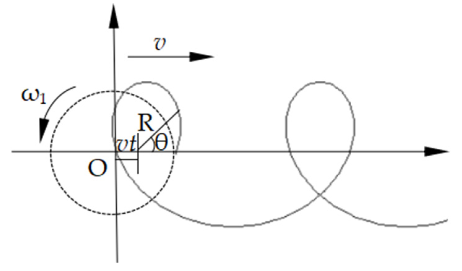
2.2.2. Design of Drip Irrigation Belt Beating Mechanism

The motion diagram of the drip irrigation beating mechanism is shown in Figure 4. When the mechanism is working, it rotates relative to the machine (as shown in the dashed circle in Figure 4), and its absolute motion trajectory should be the cycloid, as shown in Figure 4. It applies a certain frequency of tapping to the drip irrigation belts to be recovered so that the drip irrigation belts can shake off debris such as soil, plastic film, and straw as much as possible under the vibration caused by tapping. This process is the first step in completing the recovery of drip irrigation belts in the field, and its performance has a significant impact on the overall operational efficiency of the machine.
To ensure the good working performance of the drip irrigation belt-beating mechanism, it is necessary to design its structure and motion parameters. Firstly, a Cartesian coordinate system was established and kinematic analysis was performed on the beating mechanism, as shown in Figure 4. The absolute motion trajectory of a point on the beating mechanism satisfies Equation (5).
x 1 = v t + R cos ω 1 t y 1 = R sin ω 1 t
where x1 represents the horizontal displacement of the beating mechanism, m; y1 is the vertical displacement of the beating mechanism, m; R is the radius of the mechanism, m; ω1 is the angular velocity of the beating mechanism, rad/s.
Then, the derivative of the above equation was taken to obtain its velocity calculation formula, as shown in Equation (6).
v x = v R ω 1 sin ω 1 t v y = R ω 1 cos ω 1 t
where vx is the horizontal velocity of the beating mechanism, m/s; vy is the vertical velocity of the beating mechanism, m/s.
The absolute motion speed of the beating mechanism can be obtained through Equation (7).
v 2 = v x 2 + v y 2 = ( v R ω 1 sin ω 1 t ) 2 + ( R ω 1 cos ω 1 t ) 2
where v2 is the absolute motion speed of the beating mechanism, m/s.
Then, the accelerations of the beating mechanism in the horizontal and vertical directions satisfy Equation (8).
a x = R ω 1 2 cos ω 1 t a y = R ω 1 2 sin ω 1 t
where ax and ay are the accelerations of the beating mechanism in the horizontal and vertical directions, respectively, m/s2.
The absolute acceleration of the beating mechanism satisfies Equation (9). From this equation, it can be seen that when the beating mechanism rotates at a constant speed, its absolute acceleration is the centripetal acceleration. Moreover, its numerical value is directly proportional to the square of the radius and angular velocity of the beating mechanism.
a = a x 2 + a y 2 = R ω 1 2 = a n
where a is the absolute acceleration of the beating mechanism, m/s2; an is the normal acceleration of the beating mechanism, m/s2.
Through the kinematic analysis of the beating mechanism mentioned above, it can be concluded that the larger the size of the beating mechanism and the higher the rotational speed, the greater its speed and acceleration. At this point, the force and acceleration applied by the beating mechanism to the drip irrigation belt instantly increase. Afterwards, the drip irrigation belt will leave the beating mechanism along its direction of force. Finally, under the influence of gravity and air resistance, the drip irrigation belt ultimately falls onto the beating mechanism. Therefore, drip irrigation belts will vibrate at a certain frequency and amplitude under the action of the beating mechanism, until this part of the drip irrigation belt is entangled by the winding mechanism. In order to ensure that the beating mechanism can effectively remove debris from the drip irrigation belt and not apply too much impact force to the drip irrigation belt and avoid excessive power consumption, the structure and motion parameters of the beating mechanism need to be selected appropriately. In this study, the radius of the belt-beating mechanism was taken as 250 mm and the width was taken as 500 mm. Then, the angle speed of the beating mechanism is set to twice the value of the winding mechanism.

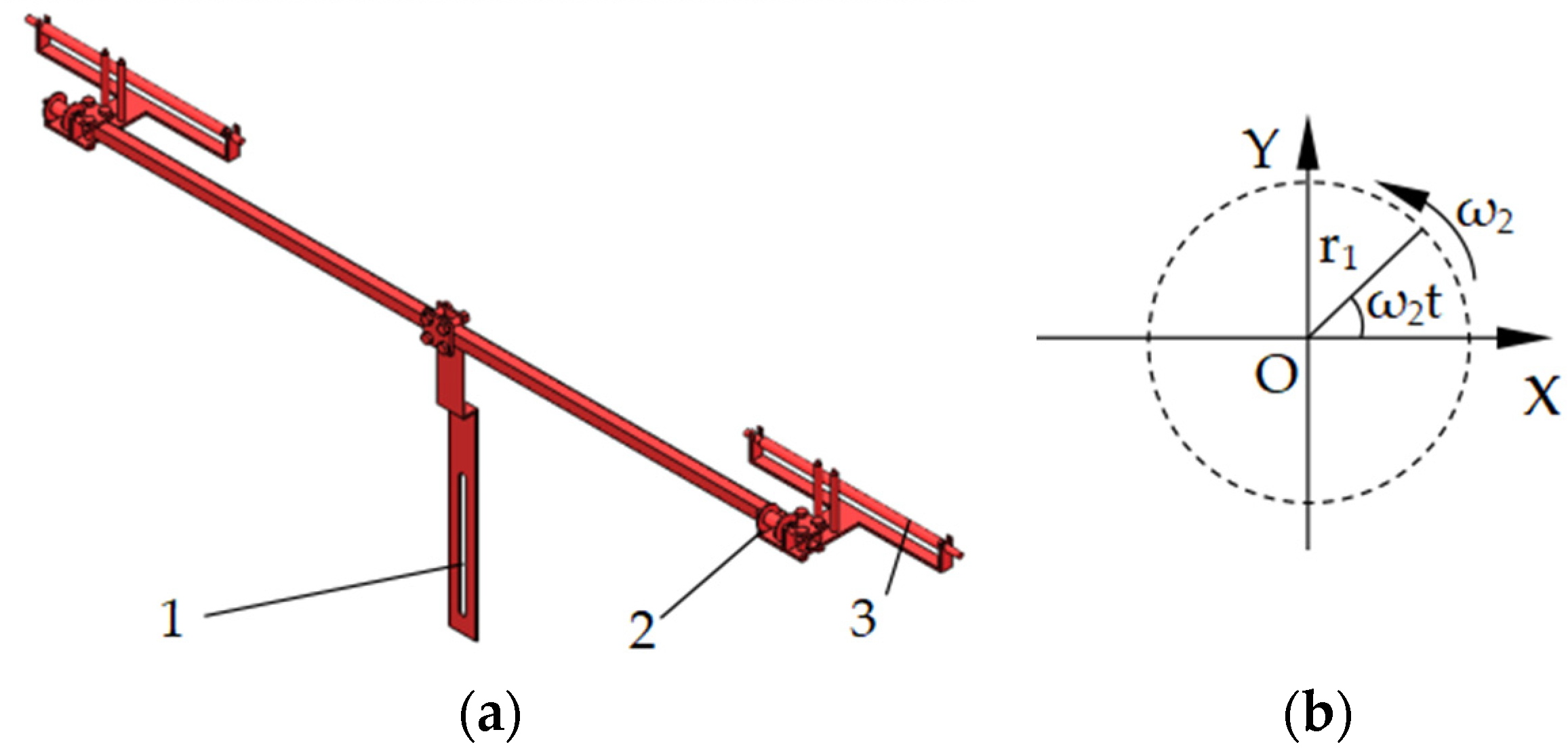
2.2.3. Design of Belt Arrangement Mechanism

The main structure of the belt arrangement mechanism and the crank motion diagram of the driving mechanism are shown in Figure 5. By using a crank and a slide, the rotational motion of the crank is transformed into a reciprocating linear motion of the drip irrigation belt conveyor mechanism, guiding the uniform laying of drip irrigation belts on the winding mechanism.
In an ideal state, when the winding mechanism wraps around the drip irrigation belt once, the drip irrigation belt arrangement mechanism needs to move horizontally by a distance of the width of the drip irrigation belt. In this way, the drip irrigation belt can be evenly wound around the winding mechanism. The schematic diagram of the movement of the crank slide mechanism is shown in Figure 5b, and the kinematic equation of the drip irrigation belt conveyor mechanism in the horizontal direction satisfies Equation (10).
X = r 1 cos ω 2 t v X = r 1 ω 2 sin ω 2 t
where X represents the horizontal displacement of the belt conveyor mechanism, m; vX is the speed of the mechanism in the horizontal direction, m/s.
In theory, the movement speed of the drip irrigation belt arrangement mechanism should satisfy the first equation in Equation (11). However, according to Equation (10), it can be seen that the motion speed of the drip irrigation belt arrangement mechanism varies continuously according to a harmonic function. Therefore, when determining the specific motion speed of the drip irrigation belt arrangement mechanism, the effective speed (v’X) is used instead of its actual speed (vx). So, the effective value of the movement speed of the drip irrigation belt arrangement mechanism is calculated using the second equation in Equation (11).
b × 10 3 v X = 2 π ω v X = v X m 2
where b is the width of the drip irrigation belt, mm; v’X is the effective value of the horizontal motion speed of the drip irrigation belt arrangement mechanism, m/s; and vXm is the maximum horizontal motion speed of the drip irrigation belt arrangement mechanism, m/s.

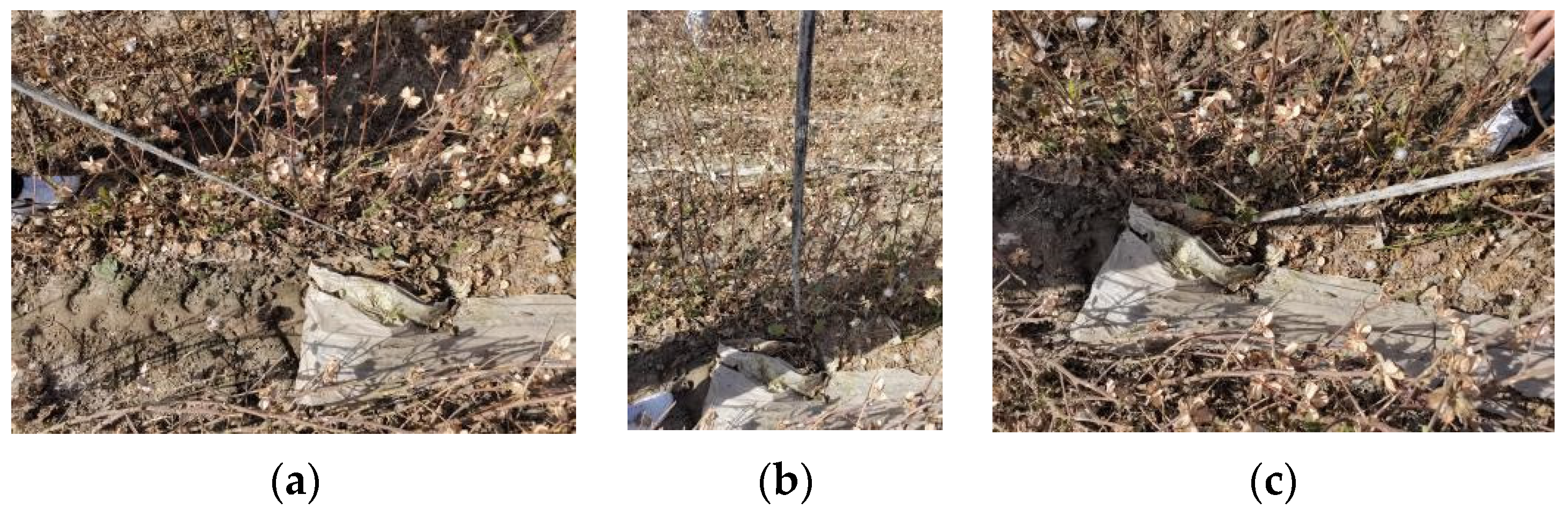
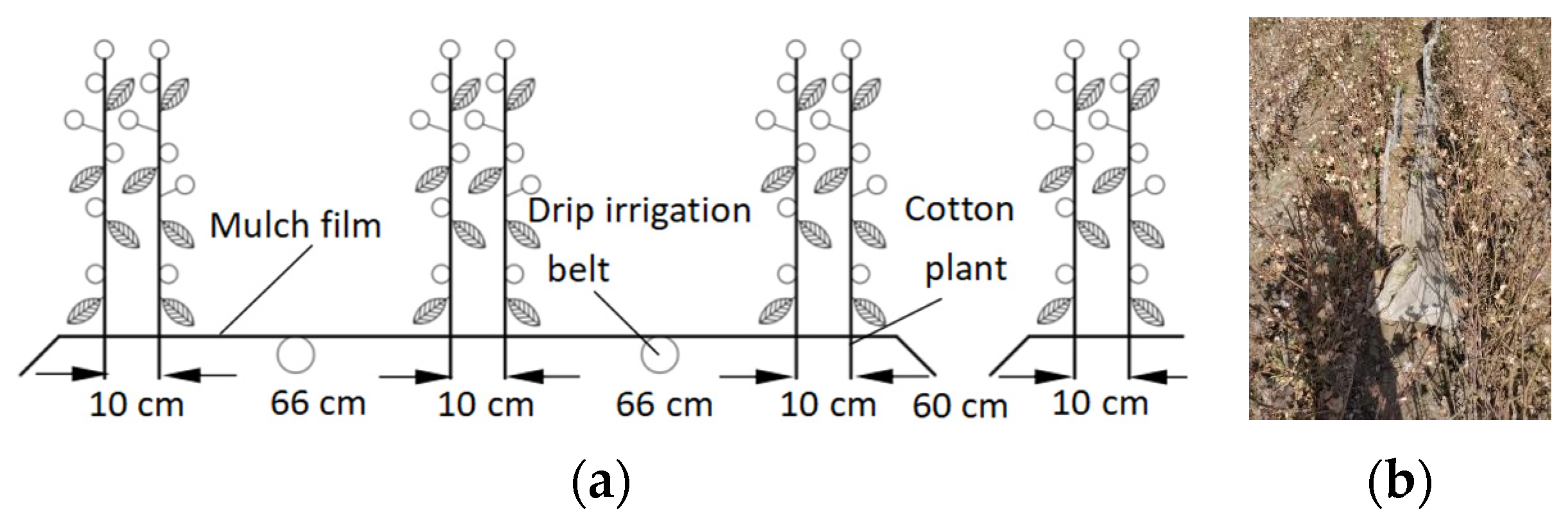
2.3. Experimental Design

2.3.1. Equipment and Materials for Test

In order to verify the performance of the newly designed drip irrigation belt recovery machine, two different pieces of drip irrigation belt recovery equipment were used in the experiment. One of them is the new drip irrigation belt recovery machine designed in this study and the other is the widely used machine, used here as a control, as shown in Figure 6. It is manufactured by Xinjiang Alar Jinzhun Machinery Manufacturing Co., Ltd. (Alar, China). The machine in the control group is a tractor-mounted traction type, which is powered by the ground wheels. During the movement of the ground wheel, the power is transmitted to the drip irrigation belt recovery mechanism through chain transmission, and then the drip irrigation belt recovery operation is carried out. When unloading the drip irrigation belts, the machine requires manual removal of them from the winding mechanism. The length and radius of the winding mechanism of the two machines used in the experiment are equal. The control group’s machine does not have a belt-beating mechanism, and there is no torque limiter on the transmission shaft of the winding mechanism. In addition, the ratio of the rotational angular velocity of the winding mechanism to the ground wheel angular velocity is a constant value.
The experiment was conducted in cotton fields in Xinjiang, and the planting mode and drip irrigation belt-laying method in the cotton fields are shown in Figure 7a. The field conditions during the drip irrigation belt recovery operation are shown in Figure 7b. The drip irrigation belts (produced by Xinjiang Hongtianyun Pipe Industry Co., Ltd., Fukang, Xinjiang, China) used in the experiment have a wall thickness of 0.2 mm and an outer diameter of 16 mm. The emitter discharge of the experimental cotton field was 2 L/h, and the cotton was irrigated 10 times during the entire growth period, with a cumulative irrigation water volume of 4500 m3/hm2.

2.3.2. Methods of Experiment and Data Analysis
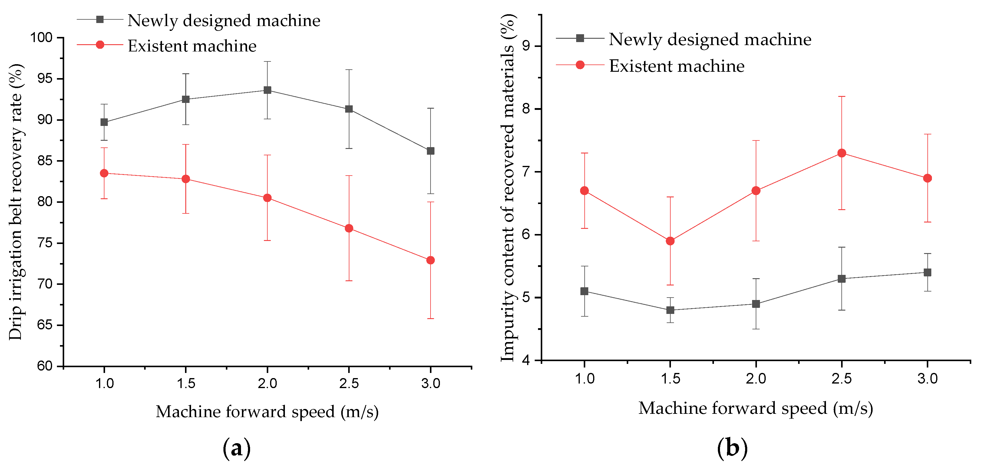
According to the technical specifications and testing methods of drip irrigation belts in the national standard GB/T17187-2009, the two types of drip irrigation belt recovery machines were tested. The experiment was conducted based on the type and operating speed of the machines. The drip irrigation belt recovery rate and the impurity content of the recovered drip irrigation belt were used as performance evaluation indicators for the machines. For each machine experiment, 25 test areas in the field were randomly selected, with a length and width of 100 × 25 m for each test area. The experiments were repeated 5 times for each test parameter. Then, the average of these 5 test results will be used as the final result of the performance evaluation index of the drip irrigation belt recovery machine under this operating parameter. All the drip irrigation belts and impurities recovered from each experimental area were brought back to the laboratory for determination of drip irrigation belts and impurity content. The specific calculation method for the evaluation index of drip irrigation belt recovery rate is shown in Equation (12). All major impurities obtained from each experiment were selected and collected, and the weight of each component was measured as a percentage of the total recovered weight in the same conditions.
η = i = 1 5 w i 5 w × 100 %
where η is the recovery rate of drip irrigation belts, %; wi is the mass of drip irrigation belts recovered by the machine in the i-th experimental area, kg; and w is the mass of drip irrigation belts initially laid in each experimental area, kg.
In addition, the mean and standard deviation were calculated for each group of the test results. A normality test of the experimental data was conducted by the way of Shapiro–Wilk and the homogeneity test of variance was performed by Levene’s Test. Then, one-way ANOVA was performed to test the significance of the difference in the population means for the experimental data of the two different machines. Besides, Origin 2016 (Origin Lab Corporation, Northampton, MA, USA) was used to process the experimental data.

3. Results

The field experiment results of the drip irrigation belt recovery rate are shown in Figure 8a. The newly designed machine achieved the highest recovery rate of 93.6% at a working speed of 2 m/s. The recovery rate of the control group reached its highest value of 83.5% under the condition of an operating speed of 1 m/s. The analysis of variance showed that under the experimental conditions of an operating speed of 1–3 m/s, there was a significant difference in the performance of these two drip irrigation belt recovery machines (p < 0.001). Under the same operating speed conditions, the newly designed drip irrigation belt recovery machine had a significantly higher recovery rate than that of the control group machine.
The statistical results of the impurity content of drip irrigation belts collected by different drip irrigation belt recovery machines are shown in Figure 8b. In addition, the statistical results of the main components of impurities contained in drip irrigation belts are shown in Table 1. Among all impurities, in addition to the materials listed in the table, there are cotton leaves, cotton boll shells, and broken cotton stalks with a total content of less than 0.1%. From both Figure 8b and Table 1, It can be seen that the impurity content rate of the drip irrigation belts recovered by the newly designed machine is lower than that of the control group machine. The results of the one-way ANOVA also showed that the impurities contained in the drip irrigation belts recovered by the newly designed machine were significantly lower than those contained in the drip irrigation belts recovered by the control group machine (p < 0.001).

4. Discussion

In response to the various shortcomings of existing drip irrigation belt recovery machines, in this study, a new type of drip irrigation belt recovery machine was designed. Compared with existing recovery machines [3,4], the hydraulic drive was adopted in the newly designed recovery mechanism, and the operation parameters of each mechanism are easily adjusted. During work, the driver has a good field of vision and does not require assistance from others, reducing labor input and lowering the cost of drip irrigation belt recovery. In addition, the newly designed winding mechanism is flat rather than the traditional three-dimensional shape [14,15], which means it has a continuous beating effect on drip irrigation belts during operation. This is of positive significance for the further removal of debris from drip irrigation belts and the reduction in machine costs and operating power consumption.
The experimental results show that the drip Irrigation belt recovery rate of the newly designed machine is significantly higher than that of the control group’s machine. This is mainly related to the characteristics of the beating and winding mechanisms of the newly designed machine. The existence of a beating mechanism reduces the frequency of drip irrigation belt breakage during operation, thereby improving the drip irrigation belt recovery rate by 10.1% compared with the control group machines, and the recovery speed increased to nearly twice that of the control group machine. In addition, unlike existing drip irrigation belt recovery machines, the newly designed winding mechanism is a flat structure with a hydraulic drive and automatic portability. Compared to existing drip irrigation belt recovery machines [16,17], this winding mechanism plays an important role in improving the recovery rate and operational efficiency of drip irrigation belts, and so on. For example, it exerts a certain beating effect on the drip irrigation belts during the winding process, further removing debris on the drip irrigation belts, and compared to the control group, the impurity content rate of the drip irrigation belts recovered by the newly designed machine decreased by 1.6%. Practice has also shown that this type of mechanism is more convenient for the quick unloading of recovered drip irrigation belts compared to three-dimensional winding mechanisms. In addition, the flat winding mechanism has a simpler structure, lower manufacturing cost, lighter weight, and lower operating power consumption. Additionally, the impurities contained in the drip irrigation belts recovered by the newly designed machine were significantly lower than those in the drip irrigation belts recovered by the control group machine. This is mainly because the newly designed beating mechanism, winding mechanism, and impurity removal roller can effectively remove soil and other debris on the surface of drip irrigation belts.
Although the newly designed drip irrigation belt recovery machine has significantly improved operational performance compared to existing machines, there are still some areas that need further research and improvement [26]. For example, after the collection of drip irrigation belts, the hydraulic unloading is completed, but the machine cannot automatically collect and transport the collected drip irrigation belts [27]. This has brought inconvenience to subsequent work and is not conducive to further reducing operational costs [28]. Therefore, further research can be conducted on how to further improve machine automation and joint operation capabilities in the future. This will be of great significance for cost saving and efficiency improvement in the operation of drip irrigation belt recovery machines.

5. Conclusions

In this study, a new type of drip irrigation belt recovery machine was designed to address a series of issues such as low operational efficiency and poor quality when existing drip irrigation belt recovery machines were used to recover drip irrigation belts from cotton fields in Xinjiang. Field performance tests and comparisons were conducted between the newly designed machine and the existing one. The experimental results show that the newly designed machine significantly improved its performance in the two important indicators of drip irrigation belt recovery rate and impurity content. In addition, compared to existing machines, the new one not only improves work efficiency and quality but also has the advantages of less labor input and lower operating costs.

Author Contributions

Resources, X.W. and J.R.; data curation, Z.S.; writing—original draft preparation, J.R.; writing—review and editing, W.G.; visualization, J.R. and Q.Z.; supervision, X.W.; project administration, X.W. All authors have read and agreed to the published version of the manuscript.

Funding

This research was funded by the Scientific and Technological Planning Projects of First Division Alar City, Xinjiang Construction Corps, grant number 2022ZB04.

Institutional Review Board Statement

Not applicable.

Data Availability Statement

The data presented in this study are available upon request from the corresponding author.

Acknowledgments

The authors acknowledge the assistance of Alar Jinzhun Machinery Manufacturing Co., Ltd, Alar, China.

Conflicts of Interest

The authors declare no conflicts of interest.

References

  1. Yuan, S.Q.; Li, H.; Wang, X.K. Status, problems, trends and suggestions for water-saving irrigation equipment in China. J. Drain. Irrig. Mach. Eng. 2015, 33, 78–92. [Google Scholar]
  2. Zhai, G.L.; Chen, G.; Feng, J.J. Simulative experiment of clogging performance of the dripirrigationtape with three-stage path. Trans. CSAE 2006, 22, 36–39. [Google Scholar]
  3. Jiang, Z.C.; Shi, J.X. Design and experiment on the drip irrigation belt recovering machine. Xinjiang Agric. Mech. 2016, 19–20. [Google Scholar] [CrossRef]
  4. Niu, H.L.; Wang, J.K.; Luo, W. Design of 4DJ type drip irrigation belt recovery machine. Xinjiang Agric. Mech. 2017, 5–7. [Google Scholar] [CrossRef]
  5. Dong, L.X.; Cui, J.W.; Sun, G.X. Study on the performance and application of minor-caliber drip tape. Water Sav. Irrig. 2006, 10–12. [Google Scholar]
  6. Han, H.; Du, W.L.; Chang, R. The tensile test research of old drip tapes. Water Sav. Irrig. 2015, 24–26. [Google Scholar]
  7. Li, X.W.; Shi, J.C.; Wang, S. Numerical simulation and analysis on depth of disposable tape in cotton field under subsurface drip irrigation in Xinjiang, China. Trans. Chin. Soc. Agric. Mach. 2017, 48, 191–198. [Google Scholar]
  8. Xu, F.P.; Li Yun, K.; Ren, S.M. Investigation and discussion of drip irrigation under mulch in Xinjiang Uygur Autonomous Region. Trans. CSAE 2003, 19, 25–27. [Google Scholar]
  9. Kong, F.Y.; Hu, T.J. Underground drip irrigation test in different drip irrigation zone with different lay intervals. Chin. Agric. Sci. Bull. 2004, 20, 331–333. [Google Scholar]
  10. Ran, J.H.; Ren, Y.; Guo, W.S.; Hu, C.; Wang, X.F. Aging characteristics of drip irrigation belt in Xinjiang cotton fields and their effects on its recovery and recycling. Sci. Rep. 2023, 13, 16948. [Google Scholar] [CrossRef]
  11. Sahin, M. Potential use of subsurface drip irrigation systems in landscape irrigation under full and limited irrigation conditions. Sustainability 2023, 15, 15053. [Google Scholar] [CrossRef]
  12. Hilaire, R.S.; Arnold, M.A.; Wilkerson, D.C.; Devitt, D.A.; Hurd, B.H.; Lesikar, B.J.; Zoldoske, D.F. Efficient water use in residential urban landscapes. HortScience 2008, 43, 2081–2092. [Google Scholar] [CrossRef]
  13. Orta, A.H.; Todorovic, M.; Ahi, Y. Cool-and warm-season turfgrass irrigation with subsurface drip and sprinkler methods using different water management strategies and tools. Water 2023, 15, 272. [Google Scholar] [CrossRef]
  14. Ding, S.S.; Li, T.W.; Wang, J.K. Analysis of power consumption of 4HS type drip irrigation belt recovery machine. J. Chin. Agric. Mech. 2015, 36, 299–302. [Google Scholar]
  15. Gong, H.H.; Wang, J.K.; Duan, W.X. Design of 4HR type drip irrigation belt recovery machine. Xinjiang Agric. Mech. 2015, 9–11. [Google Scholar] [CrossRef]
  16. Tang, A.M.; Luo, J.H. Dyestripping and recovery of 2JMSD-4.5 type drip irrigation belt machine. Xinjiang Agric. Mech. 2008, 12. [Google Scholar] [CrossRef]
  17. Tian, X.L.; Zhao, Y.; Chen, X.G. Development of 4JSM-2000A type combined operation machine for cotton stalk chopping and residual plastic film collecting. Trans. CSAE 2018, 34, 25–35. [Google Scholar]
  18. Liu, X.F.; Shi, X.; Guo, Z.F. Performance test on roller type residual film recycling machine. Trans. CSAE 2017, 33, 26–31. [Google Scholar]
  19. Zhao, Y.; Zheng, X.; Chen, X.G. Design and test of CMJY-1500 type plastic film residue collecting and balling machine. Trans. CSAE 2017, 33, 1–9. [Google Scholar]
  20. Wang, Z.C.; Li, X.Y.; Shi, H.B. Effects of residual plastic film on soil hydrodynamic parameters and soil Structure. Trans. Chin. Soc. Agric. Mach. 2015, 46, 101–106. [Google Scholar]
  21. Zhang, J.X.; Wang, X.N.; Zhang, L. Effects of mechanical tensile properties of plastic film on plastic recycling method. Trans. CSAE 2015, 31, 41–47. [Google Scholar]
  22. Guo, W.S.; Jian, J.M.; San, Y.L. Design and experimental optimization of 4CML-1000 type chain rake film recycling machine. Trans. Chin. Soc. Agric. Mach. 2018, 49, 66–73. [Google Scholar]
  23. Zhao, Y.; Chen, X.G.; Wen, H.J. Research status and prospect of control technology for residual plastic film pollution in farmland. Trans. Chin. Soc. Agric. Mach. 2017, 48, 1–14. [Google Scholar]
  24. Xie, J.H.; Chen, X.G.; Sun, C.W. Unloading film process analysis and high-velocity photography experiment of pole-tooth residual plastic film collector. Trans. CSAE 2017, 33, 17–24. [Google Scholar]
  25. You, J.H.; Chen, X.G.; Zhang, B.H. Design and experiment of 4JSM-2000 type combined operation machine for cotton stalk chopping and residual plastic film collecting. Trans. CSAE 2017, 33, 10–16. [Google Scholar]
  26. Pu, B.S.; Chen, Y.K.; Wang, T.; Huang, Y.Y. Development status of automated guided vehicle technology and its application and prospect in agriculture. Jiangsu Agric. Sci. 2020, 48, 61–65. [Google Scholar]
  27. Xu, J. Analysis and optimization for lifting mechanism of scissor-fork lifter. Mech. Sci. Technol. Aerosp. Eng. 2013, 32, 919–922. [Google Scholar]
  28. Liu, J.Y. Force analysis of scissor lift mechanisms. J. PLA Univ. Sci. Technol. Nat. Sci. Ed. 2014, 15, 133–138. [Google Scholar]
Figure 1. Structure of the newly designed drip irrigation belt recovery machine: 1. drip irrigation belt-beating mechanism, 2. belt-arranging mechanism, 3. belt-winding mechanism, 4. hydraulic cylinder for unloading drip irrigation belts, 5. the crank of the belt arranging mechanism.
Agriculture 14 00421 g001
Figure 2. Structure of the winding mechanism: (a) shape of the winding mechanism in working state; (b) shape of the winding mechanism during unloading; 1. chute, 2. pull rod, 3. chain wheel installed on the torque limiter.
Agriculture 14 00421 g002
Figure 3. Drip irrigation belt motion state under different motion parameters of the winding mechanism: (a) the motion state of the drip irrigation belt when the motion speed of the winding mechanism is greater than that of the machine; (b) the motion state of the drip irrigation belt when the speed of the winding mechanism is equal to that of the machine; (c) the motion state of drip irrigation belts when the speed of the winding mechanism is less than that of the machine.
Agriculture 14 00421 g003
Figure 4. Schematic diagram of the movement of the belt-picking mechanism: ω1 is the angular velocity, rad/s; R is the radius of the beating mechanism, m; t is time, s; v is the forward speed of the machine, m/s; θ is angle, rad.
Agriculture 14 00421 g004
Figure 5. The structure and movement diagram of the drip irrigation belt arrangement mechanism: (a) the structure of the drip irrigation belt arrangement mechanism, 1. the slide groove of the crankshaft, 2. the directional roller, 3. the cleaning roller; (b) motion diagram of the belt arrangement mechanism, r1 is the crank radius, m; ω2 is the angular velocity of the crankshaft, rad/s; t is time, s.
Agriculture 14 00421 g005
Figure 6. Drip irrigation belt recovery machine in the control group.
Agriculture 14 00421 g006
Figure 7. Experimental cotton field conditions: (a) cotton planting mode; (b) conditions of the experimental field.
Agriculture 14 00421 g007
Figure 8. Test results of performance indicators for different drip irrigation belt recovery machines: (a) test results of drip irrigation belt recovery rate; (b) statistical results of impurity content in drip irrigation belts.
Agriculture 14 00421 g008
Table 1. Statistics of characteristics of impurity components.
ComponentsThe Percentage of Each Component in the Total Weight of Recovered Materials (%)
The Impurities Contained in Drip Irrigation Belts Recovered by the Newly Designed MachineImpurities Contained in Drip Irrigation Belts Recovered by Control Group Machine
Soil3.84.7
Mulch film0.81.1
Weed0.50.9
Total5.16.7
Disclaimer/Publisher’s Note: The statements, opinions and data contained in all publications are solely those of the individual author(s) and contributor(s) and not of MDPI and/or the editor(s). MDPI and/or the editor(s) disclaim responsibility for any injury to people or property resulting from any ideas, methods, instructions or products referred to in the content.

