3.1. Measuring Principle of Optical Sensors
The seawater is considered as an optical medium and the optical instruments obtain the salinity value mainly by measuring the refractive index of the seawater. The refractive index is directly related to density
of seawater through the Lorentz-Lorenz relation. Meanwhile, the density changes with the salinity (
S) and temperature (
T), and the refractive index also changes with wavelength (
). As a result, the salinity can be determined with refractive index. Several authors devoted to determining the empirical relationship of
) [
42,
43]. Millard and Seaver developed a 27-term index of refraction algorithm for pure water and sea waters in accordance to the four experimental data sets [
42]. The accuracy of the algorithm varying with pressure, with 0.0004 at atmosphere pressure and 0.08 at high pressures. The equation covers the range 500–700 nm in wavelength, 0–30 °C in temperature, 0–40 in salinity and 0–11,000 dbar in pressure. Quan and Fry determined a simple ten-parameter empirical equation for the refractive index as a function of salinity, temperature and wavelength at ambient pressure that can be expressed as [
43]:
where
S is the salinity,
T is the temperature in Celsius degree and
is the wavelength in nanometer (nm). The ranges of validity are 0 °C <
T < 30 °C, 0 <
S < 35, and 400 nm <
< 700 nm. This equation can reproduce the experimental data within the experimental errors.
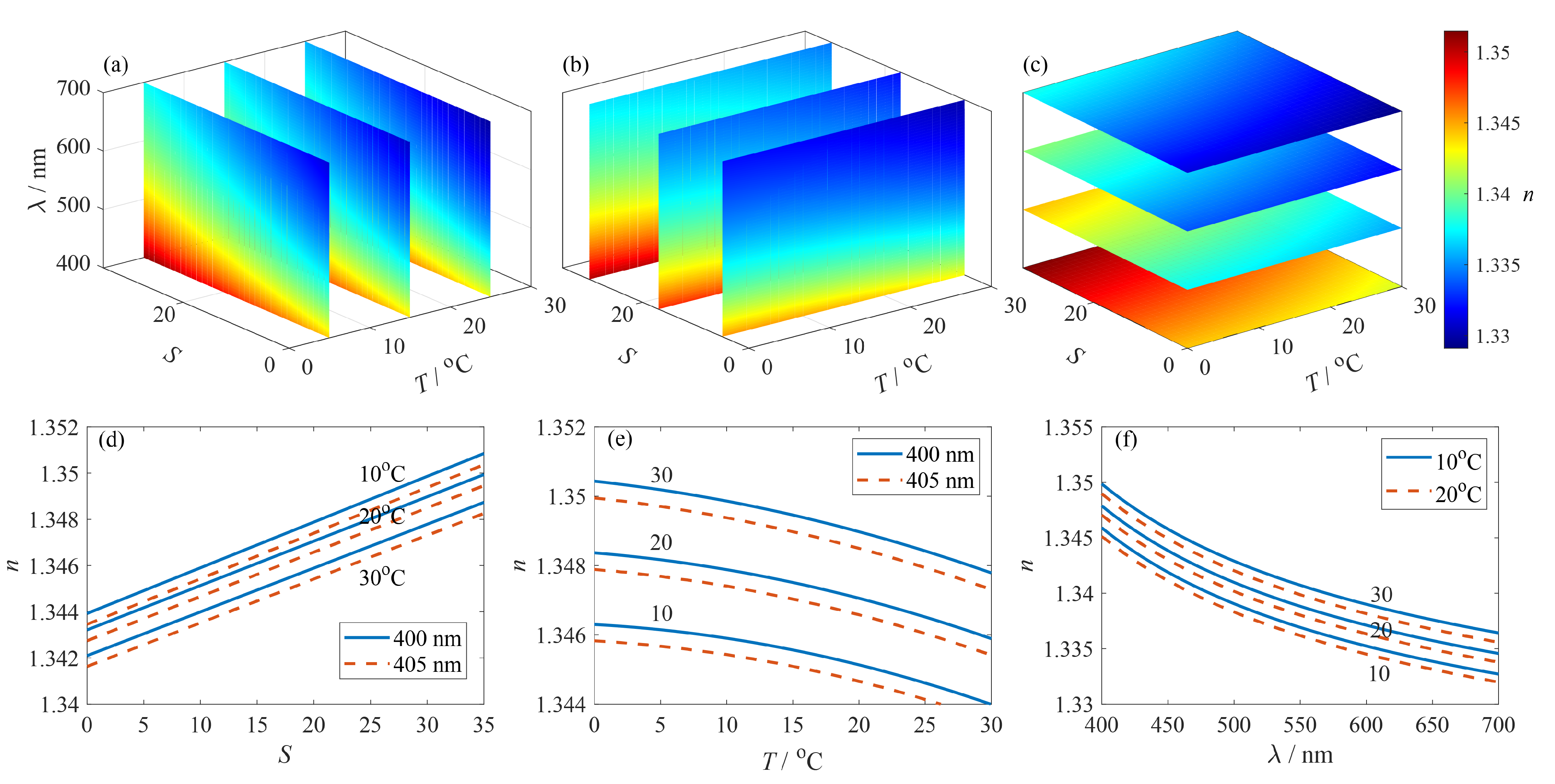
We use Equation (
5) to show the changes of refractive index with changing salinity, temperature and wavelength. The volume slice planes of temperature (
Figure 3a), salinity (
Figure 3b) and wavelength (
Figure 3c) are shown in
Figure 3.
Figure 3d–f shows the relationship between refractive index with salinity, temperature and wavelength, keeping the other two variables at different constant values. For instance,
Figure 3d shows the refractive index versus salinity under different temperature and wavelength.
As can be seen from
Figure 3d, refractive index increases linearly with salinity at different temperatures and wavelengths. This relationship is quantified in
Table 3 as the ratio of change of salinity
to change of refractive index
at different temperature-wavelength points. The data fit excellently with a linear function with all
equals to 1. The ratio
varies at different temperature-wavelength points, indicating that the temperature and wavelength have a significant influence on the measurement results.
From the above analysis, it can be seen that the refractive index has a linear relationship with the salinity of the solution. The refractive index can be directly measured by optical means. But to obtain the salinity, we also need to know the temperature and wavelength. Compared with the mature application of electronic instruments, there are only a few optical measurement products in the market, such as the NOSS sensor from NKE [
25], and other optical measurement methods are still in the research stage. Various optical measurement methods have been proposed, including measurement based on beam deviation, light wave mode coupling and swelling of surface coating material. The sensor configuration, working principle and measurement performance of these methods are reviewed in detail in the following. Since optical sensors are mainly in the research stage, this review is mainly for scientific researchers, and the measurement principle of different sensors are reviewed respectively.
3.2. Salinity Measurement Based on Beam Deviation
Figure 4 shows the principle of salinity measurement based on beam deviation. A partitioned cell is used to contain the reference solution and the sample solution. The incident angle of light at the interface of these two solutions is
and the refraction angle is
. The change of the salinity, hence the refractive index, of the sample solution will lead to the deviation of beam propagation direction. By measuring the beam deviation with a position-sensitivity detector (PSD), the salinity of the solution can be obtained.
The beam deviation method can be divided into transmission type and reflection type. As early as 1989, Minato et al. presented a salinity sensor based on transmission type refractometer [
13]. In their system, a partitioned cell was designed which was divided into two parts: one contained standard seawater (the salinity is 35) for reference, and the other was filled with sample seawater. When the salinity, hence the refractive index, of the sample seawater was different from that of the reference seawater, the beam propagating in the cell will deviate, and the refractive angle change was nearly proportional to the salinity. In this system, the salinity measurement resolution was 0.02 with an accuracy of ±0.6 from salinity range of 0 to 40. In 2003, Zhao et al. described a salinity sensor based on the measurement of the beam deviation due to the refractive angle change [
44]. In this system, the beam from a light source transmitted through a single-mode fiber before entering the sensor probe. The deviated light beam caused by water with different salinity entered the receiving fibers (40 multi-mode fibers arranged in linear array), and was then measured by the position-sensitive detector (PSD). The sensor probe mainly composed of two parts: the sample water tank containing a wedge-shaped reference cell filled with distilled water and the right-angle prism used to reflect the incident beam. The incident beam will then sequentially pass through the reference water, the oblique plate, the sample water, and then be reflected by the right-angle prism. When the salinity of the sample water changes, the deviation of the beam changes synchronously. Based on the transverse photoelectric effect, the PSD’s output signal was independent to the incident light intensity and only related to positions of the incident beam. The salinity measurement resolution was 0.012 with a salinity accuracy of 0.28 within the measurement range from distilled water to salt water with salinity of 50. It is worth to mention that the NOSS sensor from NKE is a refractometer with reflection type. The beam path has been deviated by gold mirrors deposited on angles of the prisms specially sized to reflect the beam on the PSD, making integration in a container easier [
45]. The salinity measurement accuracy is ±0.005 within the measurement range 15 to 42 [
25].
3.3. Salinity Measurement Based on Light Wave Mode Coupling
The salinity sensor based on light wave mode coupling typically obtain the salinity by means of the light transmission wave variation. The optical transmission medium is surrounded by the solution of which the salinity is to be quantified. Since the light wave interact with the surround medium, the intensity or the spectrum of the transmission wave changes with the refractive index of the surround solution. Thus high accuracy of salinity measurement can be achieved with light wave mode coupling for refractive index measurement. The light wave mode coupling method can be divided into light intensity detection and wavelength detection.
Figure 5a shows the schematic diagram of salinity measurement based on light intensity detection. The sensor probe is immersed in the sample solution, and the light emitted by the light source reaches the detector through the optical fibers and the sensor probe. The evanescent field of the guided mode will extend into the solution. Different salinity leads to different coupling efficiencies of the incident light field into the solution, so the detection light intensity varies. The sensor probe can be realized in many ways, such as surface-plasmon resonance, tapered optical fiber or U-shaped plastic optical fiber. In these sensor probes, some light will radiate into the solution as the evanescence wave, and the variation of the salinity in water will lead to the change of the light intensity in the fiber. In 1999, Esteban et al. used a fiber-optic sensor based on surface-plasmon resonance to measure the salinity of water [
46]. The sensor probe consisted of a metallic layer deposited on a side-polished single mode optical fiber. A part of the evanescent field of the guided mode is coupled as a surface plasmon in the metallic layer. This effect reduced the power transmitted by the fiber and the attenuation was strongly dependent on the refractive index, hence the salinity, of the external solution that was in contact with the metallic layer. The measurement accuracy was ±0.1 in the salinity range from 0 to 40. In 2011, Rahman et al. demonstrated a simple tapered plastic multi-mode fiber-optic sensor for monitoring of salinity [
47]. The sensor probe was a tapered fiber which was fabricated using a heat-pulling method to achieve a waist diameter and length of 0.187 mm and 5 mm respectively. The tapered fiber was immersed in the solution during measurement. The increment of salinity concentration increased the refractive index of the solution, which in turn reduced the index difference between core and cladding of the tapered fiber and thus allows less lights to be transmitted. The salinity measurement resolution was 1.152 with a sensitivity of 0.00024 mV and a salinity accuracy of ±2.532 when the solution concentration varies from 0 to 120. In 2012, Wang et al. directly used a plastic multi-mode optical fiber to measure salinity [
48]. U-shaped and spiral-shaped plastic optical fibers were used as sensor probes. Some light will radiate into the ambient solution of the sensor as the evanescence wave. Therefore, the variation of the salinity in water will lead to the change of the light intensity in the fiber. In their experiment, the sensitivities of the U-shaped sensor probe was 0.042 mV with a salinity accuracy of about ±7.14 when the NaCl concentration varied from 0 to 350.
Although the salinity sensor based on intensity detection has a simple structure, the light intensity is easily affected by other factors, such as turbidity and bubbles, to limit its measurement accuracy. In order to improve the measurement accuracy, wavelength detection is used.
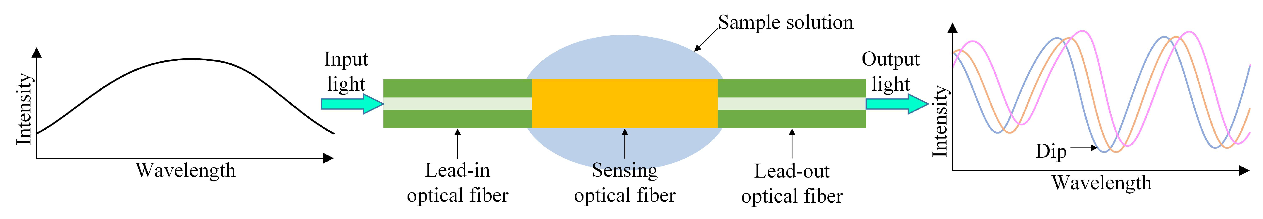
Figure 6 shows the schematic diagram of salinity measurement based on wavelength detection. The sensor usually consists of lead-in optical fiber, sensing optical fiber and lead-out optical fiber. The lead-in and lead-out fibers are usually single-mode fibers (SMFs). The sensing fiber can be realized in many ways, such as two-core fiber, no-core fiber, or photonic crystal fiber, etc. The sensing fiber is exposed to the sample solution resulting in obvious dips on the output light spectrum, and the salinity can be obtained by tracking the shift of the dips. Therefore, the system setup of these sensors mainly consist of a broadband light source and an optical spectrum analyzer (OSA).
In 2013, Guzman-Sepulveda et al. demonstrated a highly sensitive salinity sensor based on a two-core optical fiber [
49]. The sensor was fabricated by splicing a section of two-core fiber (TCF) between two single-mode fibers (SMFs). The central core was treated as the transmitting core while the off-axis core, the cladding around which was controllably removed by means of wet chemical etching, was treated as the coupling core. The TCF cladding around the off-axis core was etched using a solution of Hydrofluoric Acid known as Buffered Oxide Etchant (BOE), which slowly removes the cladding material thus allowing detecting the starting point of the interaction between the off-axis core and the surrounding liquid, i.e., when the spectral response starts to shift. The interaction with the surrounding media will induce changes on the effective refractive index of the off-axis core and this will manifest not only in variations on the coupling coefficient but also in a difference between the propagation constants, resulting in a spectral shift. There were obvious dips on the spectrum and the wavelength shift under different salinity can be obtained by tracking the dips. Measurement sensitivity of 14.0086 nm/(mol/L) was achieved for the salinity ranges from 0 to 5 mol/L. In 2014, Meng et al. proposed an optical fiber salinity sensor based on multi-mode interference (MMI) effect [
50]. The sensor probe was manufactured by splicing a section of no-core fiber (NCF) between two single-mode fibers (SMFs), that possesses a transmission peak at a certain wavelength due to MMI effect. The input signal from the lead-in SMF entered into the NCF, where high order modes were excited and MMI-induced self-imaging effect occurs. When the sensor was surrounded by salt solution, the external solution can be regarded as the cladding of the NCF. When refractive index of the salt solution increased, the effective refractive index of the NCF will be increased because the evanescent filed penetrates deeper into the liquid, and the effective diameter of the fundamental mode will be increased because the refractive index difference between the core and cladding was reduced. Thus, salinity of the liquid that it is immersed in can be measured from wavelength shift of the transmission peak. Linear response with salinity sensitivity of 1.94 pm was achieved and the measurement range was from 38.6 to 216.2. In 2019, Yu et al. demonstrated an all fiber refractive index sensor based on an optical microfiber coupler which was fabricated by fusing and tapering two twisted conventional communication fibers [
51]. The output intensity of the coupler varied with light wavelength, thus forming a coupling spectrum that contained several dips. When external environment changed, the coupling spectrum will shift, and the measurement of salinity, temperature and depth (pressure) in seawater can be realized through monitoring the shift of the dips. The highest sensitivities of salinity, temperature, and depth were 1596 pm, 2326 pm/°C, and 169 pm/MPa respectively. In the same year, Wang et al. proposed an high-sensitivity salinity sensor with a exposed-core micro-structured optical fiber (ECF) based on a free space propagation-core mode Mach-Zehnder interferometer [
52]. The proposed sensor had a salinity measurement range from 0 to 40 and a salinity sensitivity of around −2.29 nm.
In 2020, Mollah et al. theoretically proposed an ultrahigh sensitive photonic crystal fiber (PCF) salinity sensor based on the Sagnac interferometer (SI) [
53]. In this sensor, all air holes were proposed to be filled with sea water. The refractive index of sea water variation induced birefringence changes reflected in the interference spectrum recorded by the spectrum analyser. Finite element method was used to analyze the propagation characteristics of the PCF. The achieved sensitivity was estimated to be 0.75 nm in the salinity range from 0 to 1000 (note that this is simulation data without practical significance) and the maximum salinity resolution was 0.133. Specially designed photonic crystal (PC) can also measure salinity. The PC is a multi-layer structure with a different dielectric constant in a periodic structure. As the incident light propagates through the PC, it is reflected at each interface. Under a suitable condition, constructive interference between the reflected waves occurs, and the resultant reflected wave destructively interferes with the incident wave. As a result, a forbidden band-gap appears as the resonant dip in the interference curve. In 2021, Zaky et al. theoretically studied a Tamm plasmon resonance-based one-dimensional PC sensor to calculate the salinity of seawater [
54]. The sensor consisted of prism layer, Au layer, water layer, periodically arranged multiple Si layers and SiO
2 layers, and Si substrate in sequence. The resonant dip of the reflectance spectra varied with water salinity. The proposed sensor recorded a sensitivity of 1.432 nm. Besides, Akter et al. proposed a dual-core micro-structure optical sensor based on photonic crystal fiber [
55] and Sayed et al. illustrated a two-dimensional photonic crystal salinity sensor [
56]. However, these proposals are only verified by theoretical simulation, experimental confirmation should be conducted in the future.
3.4. Salinity Measurement Based on Swelling of Surface Coating Material
Another type of salinity measurement is based on mechanical stress that is induced in the chemically sensitive water swellable polymers coating when the water escapes from it caused by salinity increase. The mechanical stress acts upon the light wave that can be quantified through optical methods. In this method, optical measurement technology such as fiber Bragg grating (FBG), Sagnac interferometer (SI) and Fabry-Perot interferometer (FPI) are usually used, while the coating material usually includes hydrogel, epoxy and polyimide (PI), etc. In 2002, Cong et al. reported an optical salinity sensor using a fiber Bragg grating (FBG) coated with hydrogel [
57]. Increase of the salinity of the surrounding solution will force water escaped from the hydrogel coating that induced mechanical stress in the coating. As a result, the stress in the hydrogel coating shifted the Bragg wavelength of the FBG. Salinity can be obtained by measuring the shift of the Bragg wavelength. In 2018, Yin et al. reported an optical salinity sensor based on an optical microfiber coil resonator (MCR) with an epoxy coil [
58]. When the salinity increased, the resonance wavelength will be red-shifted and the sensitivity can reach up to 1.5587 nm with a resolution of 0.0128. In addition to hydrogel and epoxy, another frequently used coating material is polyimide (PI). PI is an organic polymer material with good hygroscopicity, strength, anti-destructive and is environmentally friendly and safe. With these unique advantages, PI has been widely applied in optical fiber sensing areas in recent years. Once PI is dipped into distilled water, the polymer absorbs water and holds it. If salt is added to the distilled water, the net water concentration in the medium decreases that makes the PI layer to dissipate water out from it to shrinks the medium. Volume expansion and contraction of the PI layer are directly proportional to the concentration of water in the surrounding medium. In 2011, Wu et al. demonstrated a salinity sensor using a PI-coated photonic crystal fiber (PCF) Sagnac interferometer (SI) based on the coating swelling induced radial pressure on the PCF [
59]. The achieved salinity sensitivity was 0.742 nm/(mol/L) with an accuracy of 0.027 mol/L. In 2015, Zhang et al. presented a fiber Fabry-Perot (FP) interference salinity sensor based on PI-diaphragm. During salinity increased from 0 to 5.47 mol/L, the maximum sensitivity was 0.45 nm/(mol/L) [
60]. In 2019, Sun et al. developed a FBG salinity sensor coated with lamellar PI [
61]. Compared with annular PI coating, lamellar PI coating enlarged the contact area with the solution so that more water molecules can be stored or released in the coating. The experimental results indicated that the sensitivity coefficients to water salinity was −0.00358 nm while the salinity accuracy was 1.048. In 2019, Kumari et al. demonstrated a salinity sensor based on an apodized FBG characterized by Nuttall profile coated with PI [
62]. The results showed the sensor had a sensitivity of 0.0026 nm with an accuracy of 0.2015 in the range of 0 to 40.
In 2020, Zhang et al. demonstrated a distributed salinity sensor with a PI-coated polarization-maintaining photonic crystal fiber (PM-PCF) based on Brillouin dynamic grating (BDG) [
63]. The PI-coating will swell or shrink if exposed to solutions of different salinity. The deformation to the coating were converted to the birefringence modulation loaded on the PM-PCF substrate. The salinity was then distributively measured by mapping the birefringence changes on the PM-PCF by BDG. The spatial resolution was 15 cm and the salinity sensitivity was 139.6 MHz/(mol/L) with a salinity accuracy of 0.072 mol/L.
The performance of the optical salinity sensors is summarized in
Table 4. The given figures are converted to salinity to be comparable with the other sensors, such as 1 mol/L NaCl would be 58.44 g/L, so roughly a salinity of 58.44. Besides, the salinity accuracy is calculated as the ratio of the accuracy of the interrogator to the sensitivity of the proposed salinity sensor. The light wave mode coupling method is based on the change of guided wave mode with the solution concentration variation to measure salinity. Among them, sensors based on intensity detection have simple structures, while they are easily affected by external perturbations that limits their measurement accuracy. On the other hand, the sensors based on wavelength detection are less susceptible to interference, and high salinity accuracy can be obtained by extracting the wavelength interference dips. However, the fragile sensing head of different micro-structures fabricated with optical fiber shall be directly inserted into the solution, so proper packaging of the sensor is necessary in practical applications. Surface coated salinity sensors usually coat hydrogel, epoxy or polyimide material on the surface of optical fiber, and measure salinity through the transmission of mechanical stress. Since these coating materials have strong hygroscopicity, this kind of sensor can realize high sensitivity and good accuracy. However, for long-term applications, the stability of coating materials and the bonding strength between coating and optical fiber should be verified and improved.


