
Dynamics Modeling and Analysis of an Underwater Glider with Dual-Eccentric Attitude Regulating Mechanism Using Dual Quaternions

 , ,
, , 
 ,
,
Abstract
:1. Introduction
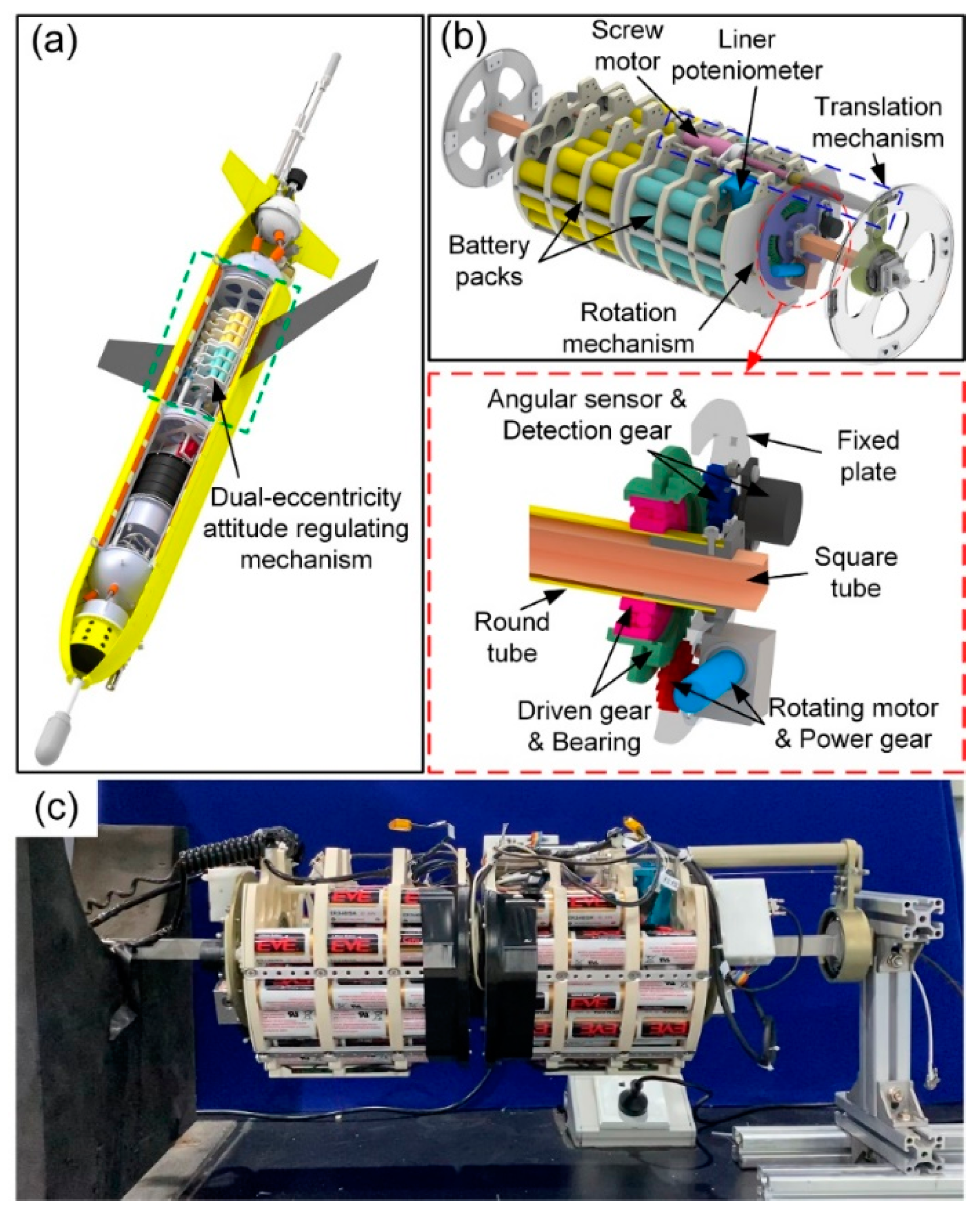
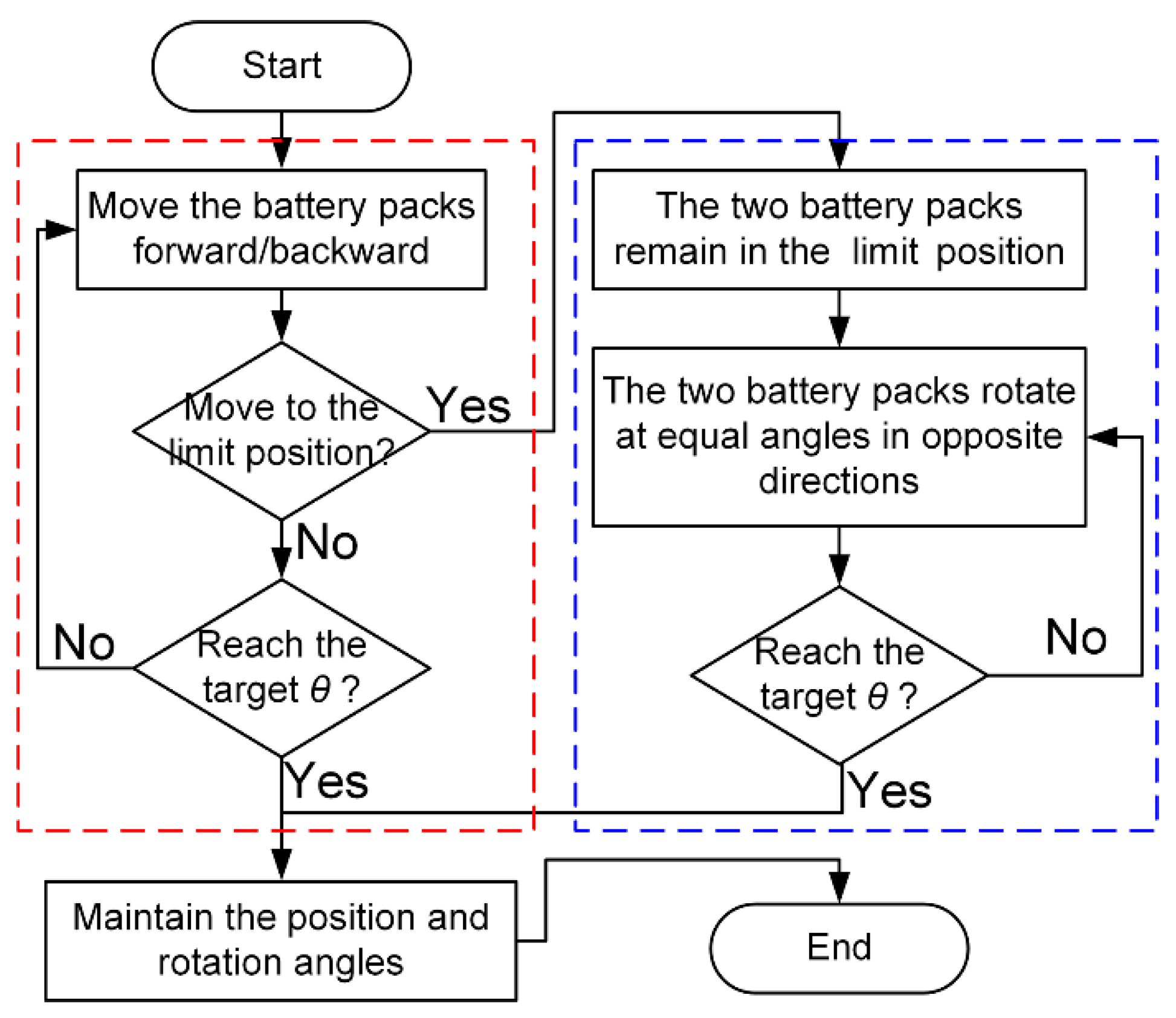
2. DARM Design
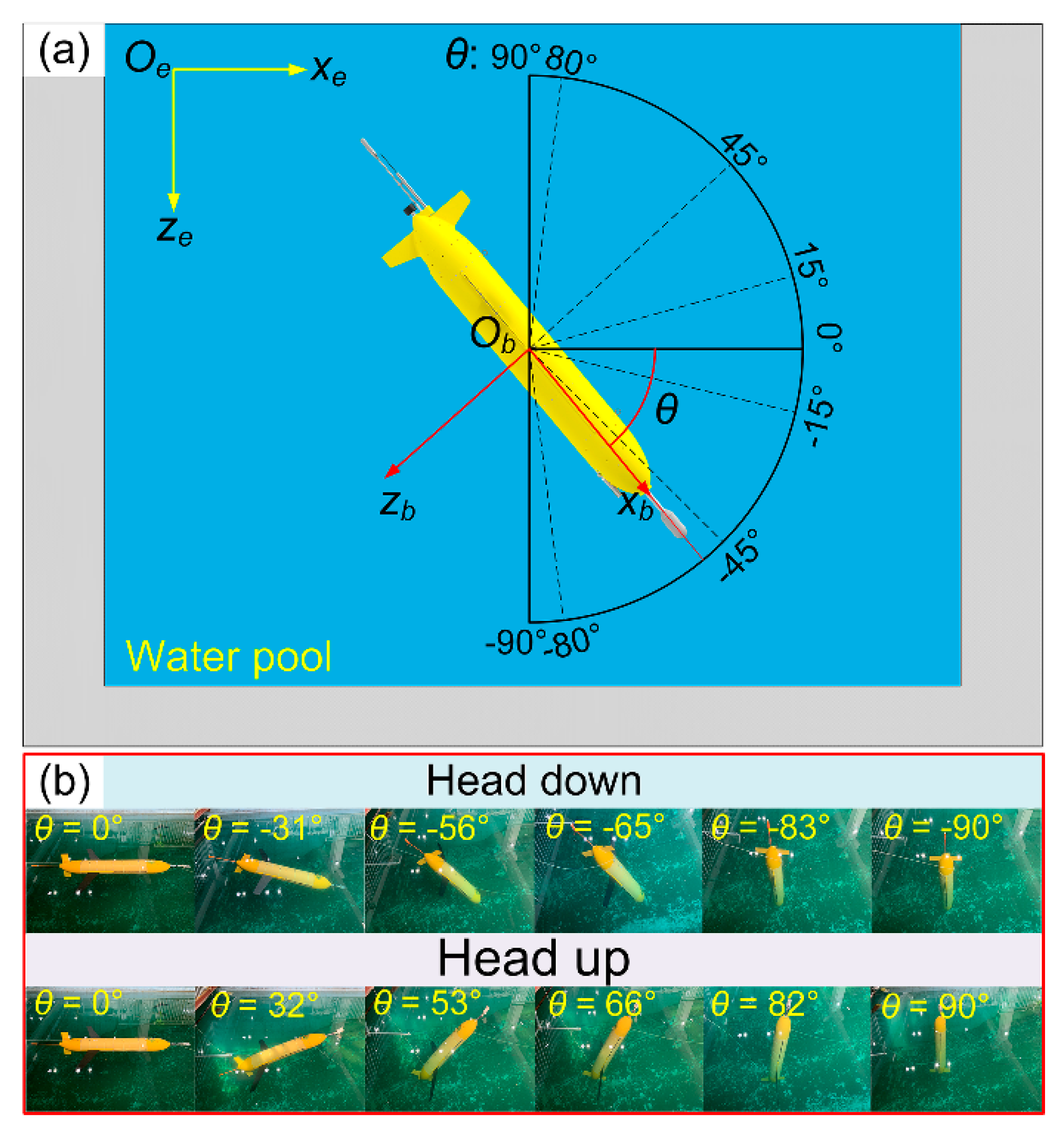
- The regulation of θ can be extended to a continuous range of −90°~90°;
- The mechanism inherits the regulation pattern of a legacy glider, including pitch and heading regulation.
- DARM can be directly replace the ARM in the legacy glider without additional installation space.
3. Dynamics Modeling
3.1. Mathematics Overview
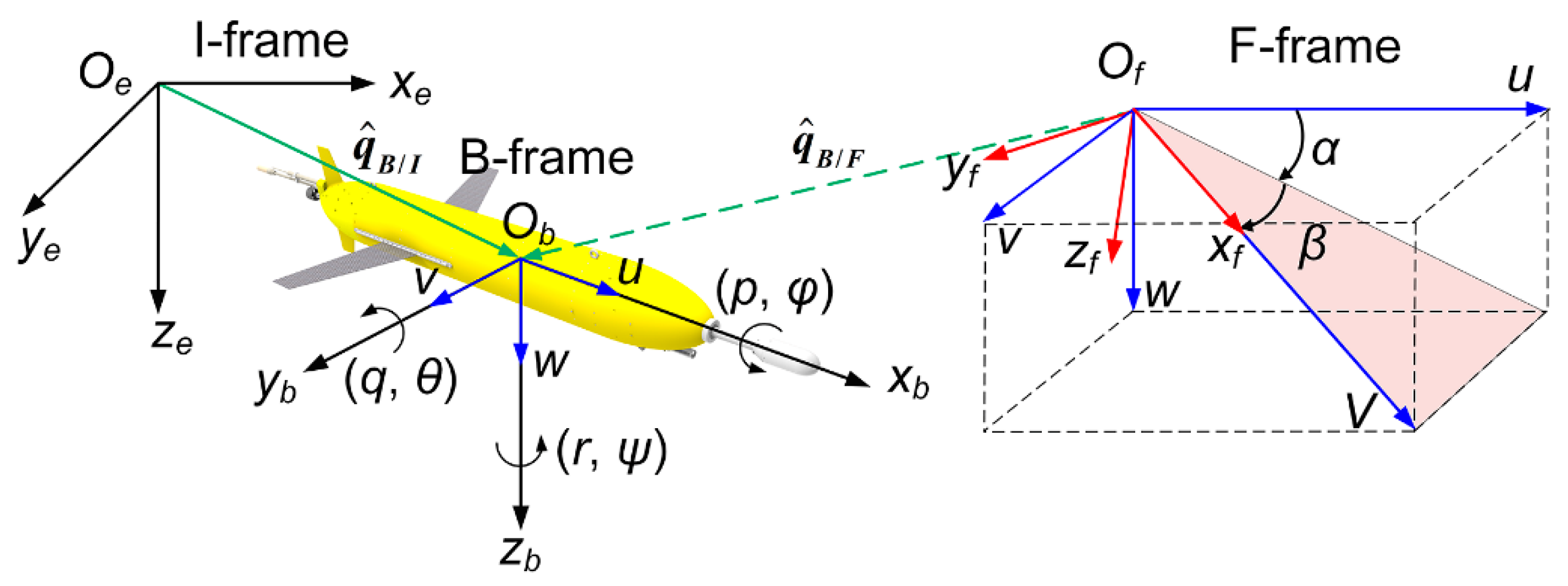
3.2. Coordinate Systems and Kinematic Equations
3.3. Force Analysis
3.3.1. Dual Buoyancy and Dual Gravity
3.3.2. Dual Net Buoyancy
3.3.3. Dual Regulation Force
3.3.4. Dual Inertia Force
3.3.5. Dual Viscous Force
3.4. Dynamic Equations
4. Motion Simulation
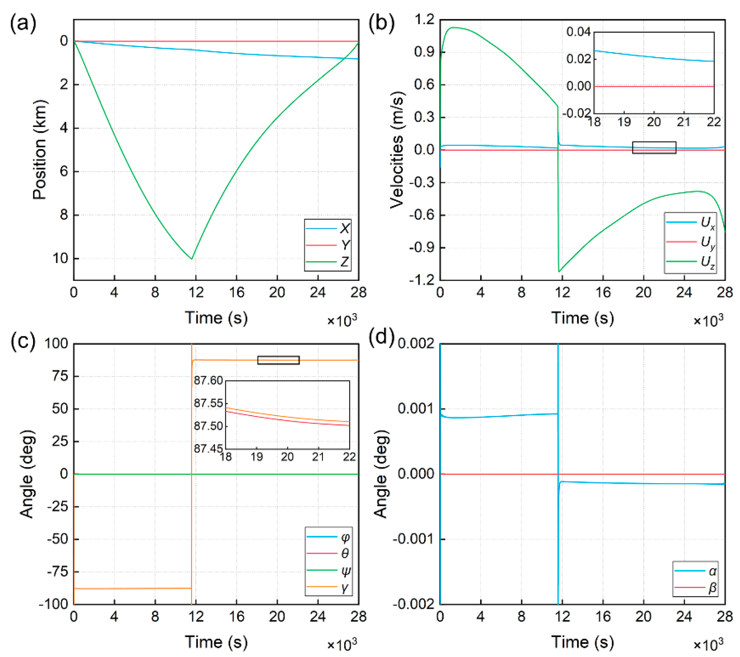
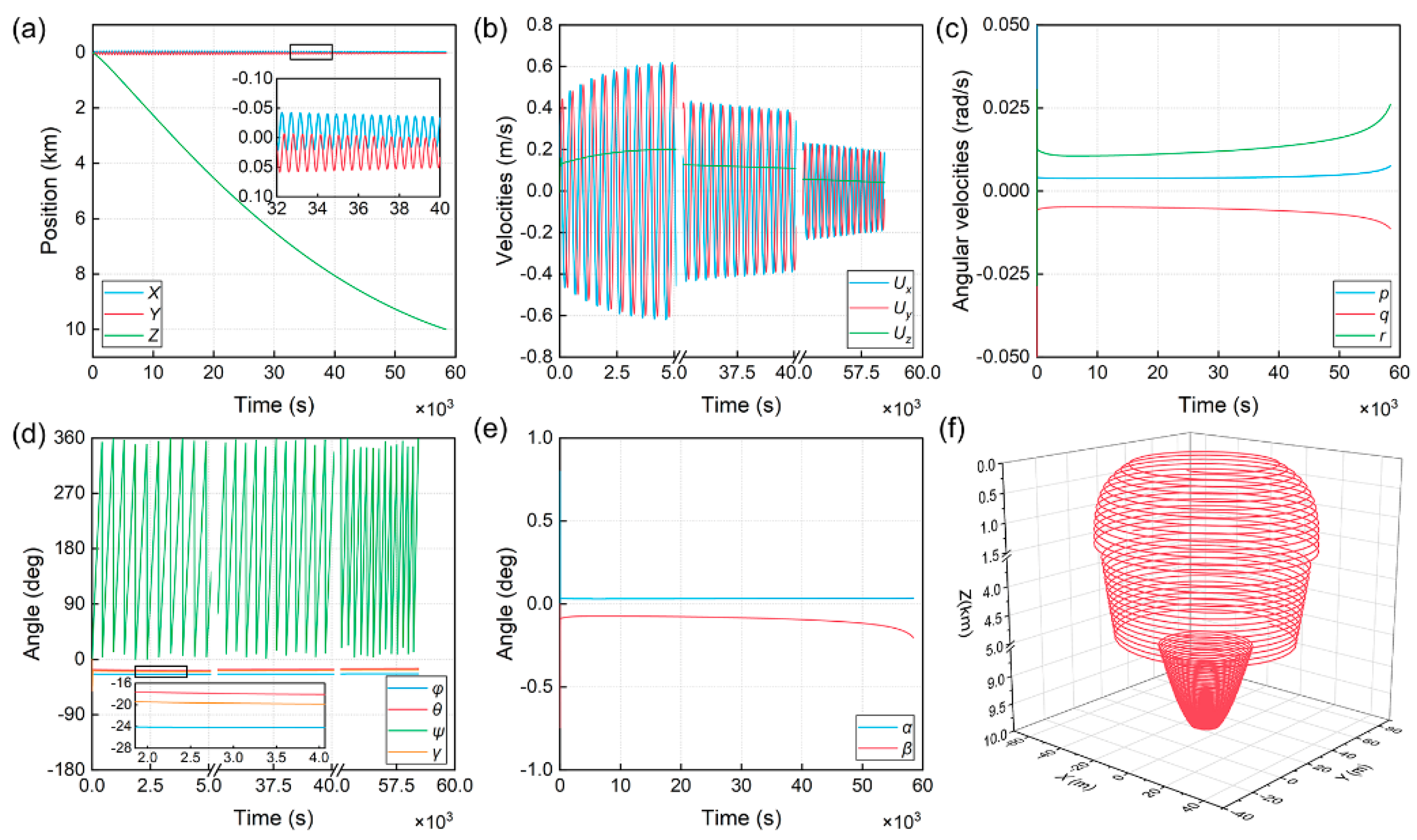
4.1. Sawtooth Motion Simulation
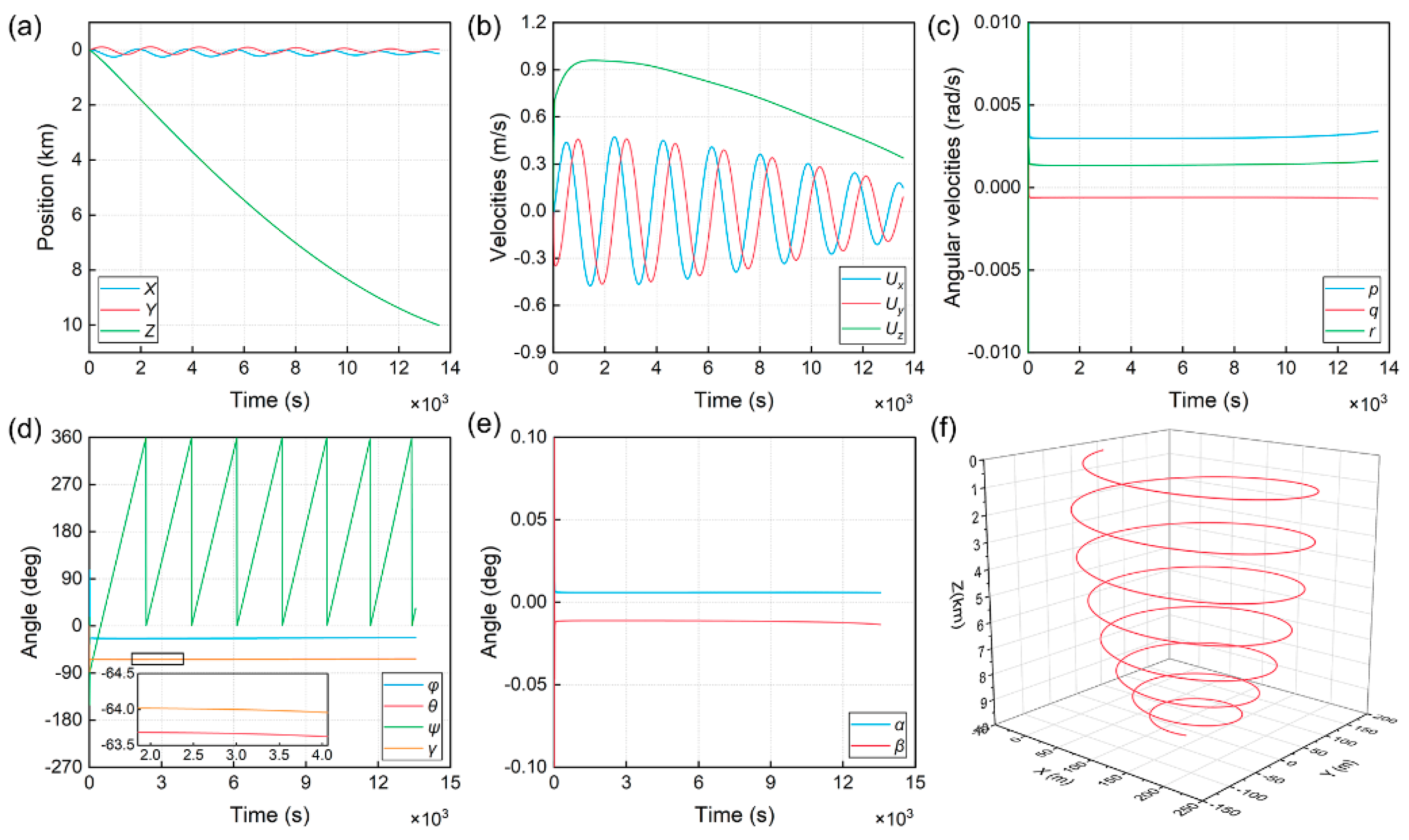
4.2. Spiral Motion Simulation
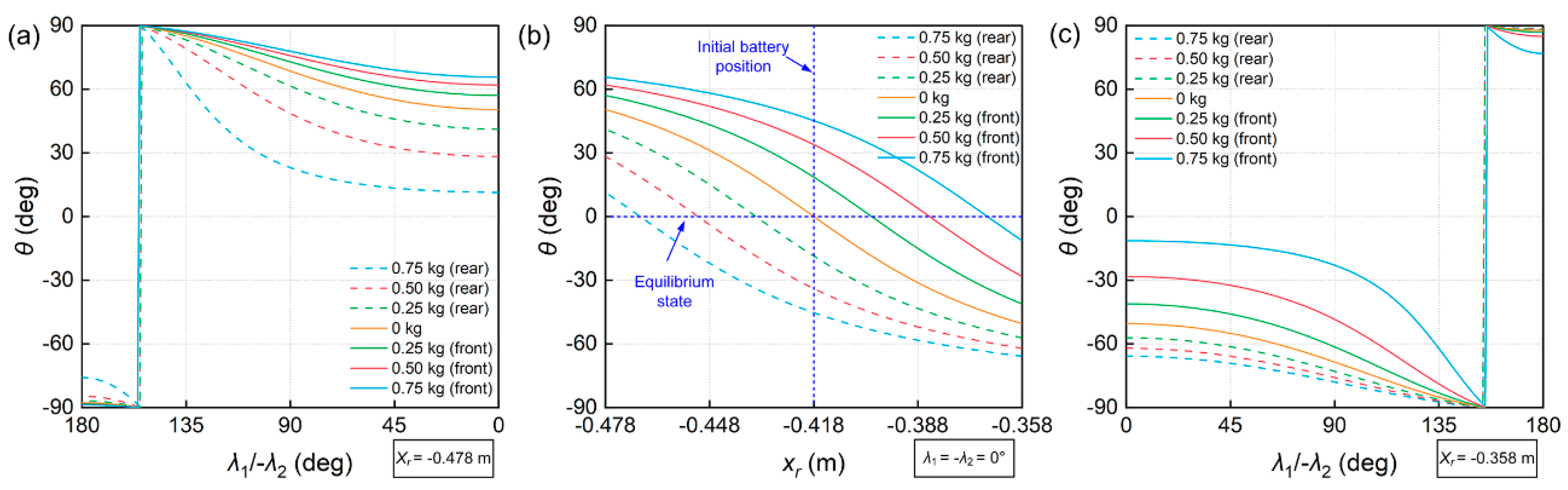
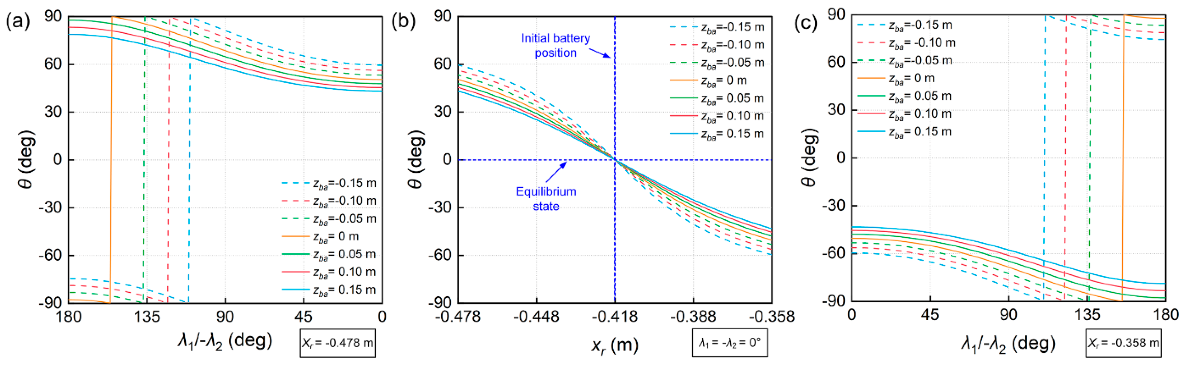
5. Ballast Method to Adjust the Pitch Angle Range
6. Experimental Verification
6.1. Water Pool Experment
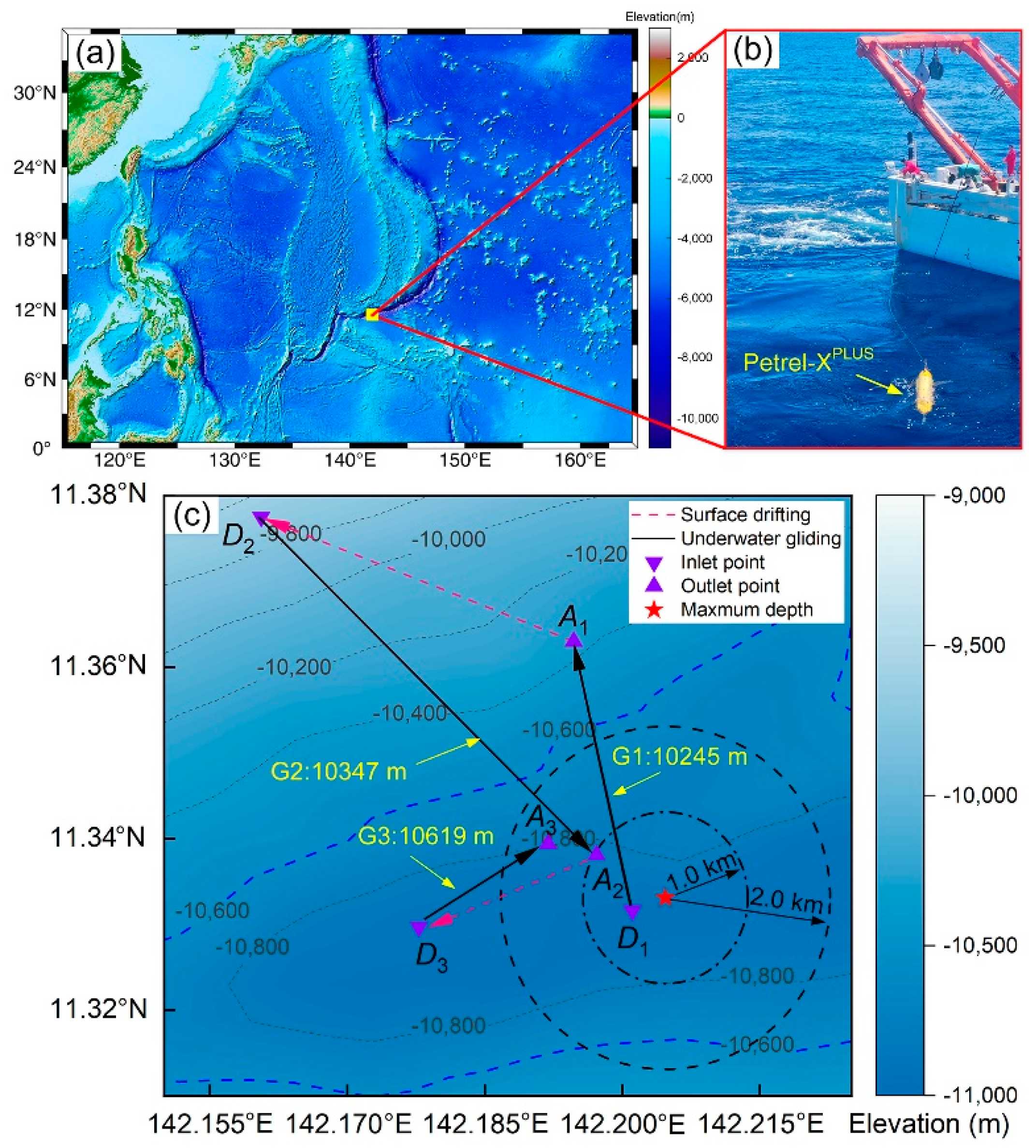
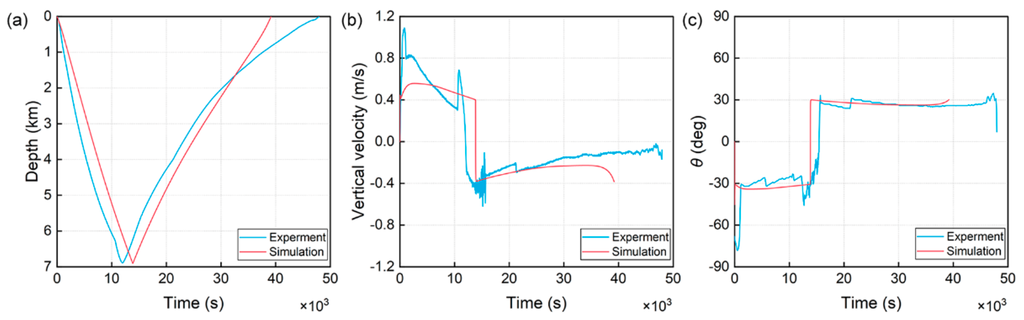
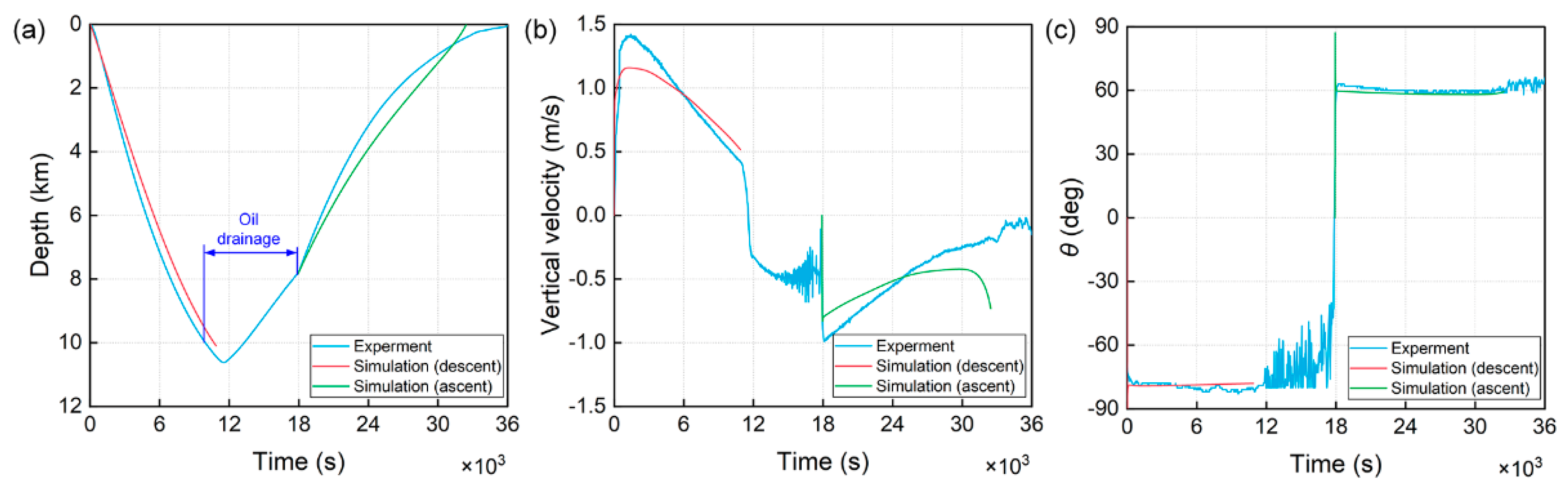
6.2. Sea Trial
7. Conclusions
Author Contributions
Funding
Institutional Review Board Statement
Informed Consent Statement
Data Availability Statement
Conflicts of Interest
Appendix A

| Operations | Formula |
|---|---|
| Addition | |
| Multiplication | |
| Multiplication by a scale | |
| Conjugation | |
| Dot product | |
| Cross product | |
| Norm | |
| Scalar part | |
| Vector part |
| Parameter | Value |
|---|---|
| Variable volume Voil | −2.5~2.5 L |
| Initial oil volume in the inner tank Voi | 2.5 L |
| Initial oil volume in the external bladder Voe | 2.5 L |
| Mass of the static part ms | 198.9 kg |
| Mass of battery pack 1 mr1 | 10.5 kg |
| Mass of battery pack 2 mr2 | 10.5 kg |
| Position of the outer bladder in B-frame ro | [0, 1.145, 0, 0]T m |
| Position of the static mass part in B-frame rs | [0, 0.257, 0, 0.0025]T m |
| Seawater density on the surface ρsea | 1021.5 kg/m3 |
| Eccentric offest of the two battery packs e | 0.025 m |
| Position of the two battery packs on the xb-axis l | −0.418 m |
| Gravitational acceleration g | 9.8 m/s2 |
| Inertia matrix about Ob JB | kg·m2 |
| Body length Lglider | 4.08 m |
| Wing span Wglider | 1.64 m |
References
- Wang, H.; Ruan, D.; Cao, C.; Fang, J.; Zhou, P.; Fang, Y.; Chen, J. Collection sediment from Mariana Trench with a novel pressure-retaining sampler. Deep Sea Res. Part I Oceanogr. Res. Pap. 2022, 183, 103740. [Google Scholar] [CrossRef]
- Jamieson, A.J.; Ramsey, J.; Lahey, P. Hadal Manned Submersible. Sea Technol. 2019, 60, 22–24. [Google Scholar]
- Bowen, A.D.; Yoerger, D.R.; Taylor, C.; McCabe, R.; Howland, J.; Gomez-Ibanez, D.; Kinsey, J.C.; Heintz, M.; McDonald, G.; Peters, D.B.; et al. Field trials of the Nereus hybrid underwater robotic vehicle in the Challenger Deep of the Mariana Trench. In Proceedings of the OCEANS 2009, Biloxi, MS, USA, 26–29 October 2009; pp. 1–10. [Google Scholar]
- Kyo, M.; Hiyazaki, E.; Tsukioka, S.; Ochi, H.; Amitani, Y.; Tsuchiya, T.; Aoki, T.; Takagawa, S. The sea trial of” KAIKO”, the full ocean depth research ROV. In Proceedings of the ‘Challenges of Our Changing Global Environment’. Conference Proceedings. OCEANS’95 MTS/IEEE, San Diego, CA, USA, 9–12 October 1995; pp. 1991–1996. [Google Scholar]
- Jamieson, A.J.; Fujii, T.; Solan, M.; Priede, I.G. HADEEP: Free-falling landers to the deepest places on Earth. Mar. Technol. Soc. J. 2009, 43, 151–160. [Google Scholar] [CrossRef]
- Jamieson, A.J. A contemporary perspective on hadal science. Deep Sea Res. Part II Top. Stud. Oceanogr. 2018, 155, 4–10. [Google Scholar] [CrossRef] [Green Version]
- Johnson, G.C.; Mecking, S.; Sloyan, B.M.; Wijffels, S.E. Recent bottom water warming in the Pacific Ocean. J. Clim. 2007, 20, 5365–5375. [Google Scholar] [CrossRef]
- Osse, T.J.; Eriksen, C.C. The Deepglider: A full ocean depth glider for oceanographic research. In Proceedings of the OCEANS 2007, Vancouver, BC, Canada, 29 September–4 October 2007; pp. 1–12. [Google Scholar]
- Yu, J.; Jin, W.; Tan, Z.; Huang, Y.; Luo, Y.; Wang, X. Development and experiments of the Sea-Wing7000 underwater glider. In Proceedings of the OCEANS 2017-Anchorage, Anchorage, AK, USA, 18–21 September 2017; pp. 1–7. [Google Scholar]
- Wang, S.; Li, H.; Wang, Y.; Liu, Y.; Zhang, H.; Yang, S. Dynamic modeling and motion analysis for a dual-buoyancy-driven full ocean depth glider. Ocean Eng. 2019, 187, 106163. [Google Scholar] [CrossRef]
- Stern, R. Subduction zones. Rev. Geophys. 2002, 40, 3-1–3-38. [Google Scholar] [CrossRef]
- Eriksen, C.C.; Osse, T.J.; Light, R.D.; Wen, T.; Lehman, T.W.; Sabin, P.L.; Ballard, J.W.; Chiodi, A.M. Seaglider: A long-range autonomous underwater vehicle for oceanographic research. IEEE J. Ocean. Eng. 2001, 26, 424–436. [Google Scholar] [CrossRef] [Green Version]
- Osse, T.; Mordy, C.; Meinig, C.; Stalin, S.; Ladd, C.; Delich, N.; Stahr, F.; Bennett, J. Oculus Coastal Glider: A New Shallow-water Oceanographic Glider. In Proceedings of the OCEANS 2018 MTS/IEEE Charleston, Charleston, SC, USA, 22–25 October 2018; pp. 1–7. [Google Scholar]
- Liu, F.; Wang, Y.H.; Wu, Z.L.; Wang, S.X. Motion analysis and trials of the deep sea hybrid underwater glider Petrel-II. China Ocean Eng. 2017, 31, 55–62. [Google Scholar] [CrossRef]
- Wang, S.; Yang, M.; Wang, Y.; Yang, S.; Lan, S.; Zhang, X. Optimization of Flight Parameters for Petrel-L Underwater Glider. IEEE J. Ocean. Eng. 2020, 46, 817–828. [Google Scholar] [CrossRef]
- Sherman, J.; Davis, R.E.; Owens, W.; Valdes, J. The autonomous underwater glider “Spray”. IEEE J. Ocean. Eng. 2001, 26, 437–446. [Google Scholar] [CrossRef]
- Webb, D.C.; Simonetti, P.J.; Jones, C.P. SLOCUM: An underwater glider propelled by environmental energy. IEEE J. Ocean. Eng. 2001, 26, 447–452. [Google Scholar] [CrossRef]
- Zhu, Y.; Yang, C.; Wu, S.; Xu, X.; Zhou, P.; Xin, S. Steering performance of underwater glider in water column monitoring. J. Zhejiang Univ. Eng. Sci. 2016, 50, 1637–1645. [Google Scholar]
- Cao, J.; Lu, D.; Li, D.; Zeng, Z.; Yao, B.; Lian, L. Smartfloat: A Multimodal Underwater Vehicle Combining Float and Glider Capabilities. IEEE Access 2019, 7, 77825–77838. [Google Scholar] [CrossRef]
- Leonard, N.; Graver, J. Model-based feedback control of autonomous underwater gliders. IEEE J. Ocean. Eng. 2001, 26, 633–645. [Google Scholar] [CrossRef] [Green Version]
- Du, X.; Zhang, X. Influence of ocean currents on the stability of underwater glider self-mooring motion with a cable. Nonlinear Dyn. 2020, 99, 2291–2317. [Google Scholar] [CrossRef]
- Song, Y.; Ye, H.; Wang, Y.; Niu, W.; Wan, X.; Ma, W. Energy Consumption Modeling for Underwater Gliders Considering Ocean Currents and Seawater Density Variation. J. Mar. Sci. Eng. 2021, 9, 1164. [Google Scholar] [CrossRef]
- Wang, Y.; Wang, S. Dynamic modeling and three-dimensional motion analysis of underwater gliders. China Ocean Eng. 2009, 23, 489–504. [Google Scholar]
- Wang, S.; Liu, F.; Shao, S.; Wang, Y.; Niu, W.; Wu, Z. Dynamic modeling of hybrid underwater glider based on the theory of differential geometry and sea trails. J. Mech. Eng. 2014, 50, 19–27. [Google Scholar] [CrossRef]
- Zhang, S.; Yu, J.; Zhang, A.; Zhang, F. Spiraling motion of underwater gliders: Modeling, analysis, and experimental results. Ocean Eng. 2013, 60, 1–13. [Google Scholar] [CrossRef]
- Yang, M.; Wang, Y.; Liang, Y.; Wang, C. A New Approach to System Design Optimization of Underwater Gliders. IEEE/ASME Trans. Mechatron. 2022, 27, 3494–3505. [Google Scholar] [CrossRef]
- Graver, J.G.; Bachmayer, R.; Leonard, N.E.; Fratantoni, D.M. Underwater glider model parameter identification. In Proceedings of the 13th International Symposium on Unmanned Untethered Submersible Technology (UUST), Durham, NH, USA, 24–27 August 2003; pp. 12–13. [Google Scholar]
- Lei, L.; Gang, Y.; Jing, G.; Chen, L. Gliding hydrodynamic modeling and identification of underwater glider based on differential evolution algorithm. Ocean Eng. 2022, 244, 110250. [Google Scholar] [CrossRef]
- Sang, H.; Zhou, Y.; Sun, X.; Yang, S. Heading tracking control with an adaptive hybrid control for under actuated underwater glider. ISA Trans. 2018, 80, 554–563. [Google Scholar] [CrossRef] [PubMed]
- Cao, J.; Lin, R.; Yao, B.; Liu, C.; Zhang, X.; Lian, L. Modeling, Control and Experiments of a Novel Underwater Vehicle with Dual Operating Modes for Oceanographic Observation. J. Mar. Sci. Eng. 2022, 10, 921. [Google Scholar] [CrossRef]
- Han, G.; Zhou, Z.; Zhang, T.; Wang, H.; Liu, L.; Peng, Y.; Guizani, M. Ant-Colony-Based Complete-Coverage Path-Planning Algorithm for Underwater Gliders in Ocean Areas with Thermoclines. IEEE Trans. Veh. Technol. 2020, 69, 8959–8971. [Google Scholar] [CrossRef]
- Li, D.; Wang, P.; Du, L. Path Planning Technologies for Autonomous Underwater Vehicles-A Review. IEEE Access 2019, 7, 9745–9768. [Google Scholar] [CrossRef]
- Xue, D.; Wu, Z.; Wang, Y.; Wang, S. Coordinate control, motion optimization and sea experiment of a fleet of Petrel-II gliders. Chin. J. Mech. Eng. 2018, 31, 17. [Google Scholar] [CrossRef] [Green Version]
- Wen, H.; Zhou, H.; Fu, J.; Zhang, X.; Yao, B.; Lian, L. Consensus protocol based attitudes coordination control for Underwater Glider formation. Ocean Eng. 2022, 262, 112307. [Google Scholar] [CrossRef]
- Liblik, T.; Karstensen, J.; Testor, P.; Alenius, P.; Hayes, D.; Ruiz, S.; Heywood, K.; Pouliquen, S.; Mortier, L.; Mauri, E. Potential for an underwater glider component as part of the Global Ocean Observing System. Methods Oceanogr. 2016, 17, 50–82. [Google Scholar] [CrossRef] [Green Version]
- Zhou, H.; Cao, J.; Fu, J.; Liu, C.; Wei, Z.; Yu, C.; Zeng, Z.; Yao, B.; Lian, L. Dynamic modeling and motion control of a novel conceptual multimodal underwater vehicle for autonomous sampling. Ocean Eng. 2021, 240, 109917. [Google Scholar] [CrossRef]
- Mukundan, R. Quaternions: From classical mechanics to computer graphics, and beyond. In Proceedings of the 7th Asian Technology Conference in Mathematics, Melaka, Malaysia, 17–21 December 2002; pp. 97–105. [Google Scholar]
- Yang, Y.; Liu, Y.; Wang, Y.; Zhang, H.; Zhang, L. Dynamic modeling and motion control strategy for deep-sea hybrid-driven underwater gliders considering hull deformation and seawater density variation. Ocean Eng. 2017, 143, 66–78. [Google Scholar] [CrossRef]
- Clark, E.B.; Branch, A.; Chien, S.; Mirza, F.; Farrara, J.D.; Chao, Y.; Fratantoni, D.; Aragon, D.; Schofield, O.; Flexas, M.M.; et al. Station-Keeping Underwater Gliders Using a Predictive Ocean Circulation Model and Applications to SWOT Calibration and Validation. IEEE J. Ocean. Eng. 2020, 45, 371–384. [Google Scholar] [CrossRef]
- Nakanishi, M.; Hashimoto, J. A precise bathymetric map of the world’s deepest seafloor, Challenger Deep in the Mariana Trench. Mar. Geophys. Res. 2011, 32, 455–463. [Google Scholar] [CrossRef]
- Taira, K.; Yanagimoto, D.; Kitagawa, S. Deep CTD casts in the challenger deep, Mariana Trench. J. Oceanogr. 2005, 61, 447–454. [Google Scholar] [CrossRef]
- Wu, H.; Niu, W.; Wang, S.; Yan, S. Prediction method of permissible error ranges of control parameters for underwater gliders under given operation accuracy. Appl. Ocean Res. 2020, 103, 102153. [Google Scholar] [CrossRef]


| Operation | Formula |
|---|---|
| Addition | |
| Multiplication | |
| Multiplication by a scale | |
| Conjugation | |
| Swap | |
| Dot product | |
| Cross product | |
| Dual norm | |
| Scalar part | |
| Vector part |
| Added Mass | Value | Added Mass | Value |
|---|---|---|---|
| λ11 | 13.90 kg | λ66 | 162.81 kg⋅m2 |
| λ22 | 201.98 kg | λ26 | −2.88 kg⋅m |
| λ33 | 268.76 kg | λ35 | 22.15 kg⋅m |
| λ44 | 11.58 kg⋅m2 | λ53 | −2.88 kg⋅m |
| λ55 | 106.41 kg⋅m2 | λ62 | 22.15 kg⋅m |
| Coefficient | Value | Coefficient | Value |
|---|---|---|---|
| KD0 | 12.01 kg/m | Kp | −41.643 kg·s/rad |
| KD | 888.63 kg/m/rad2 | KM0 | 0.03 kg |
| KS | −231.04 kg/m/rad | KM | −386.01 kg/rad |
| KL0 | −0.381 kg/m | Kq | −677.01 kg⋅s/rad2 |
| KL | 954.35 kg/m/rad | KN | 100.42 kg/rad |
| KK | 0 kg/rad | Kr | −631.63 kg⋅s/rad2 |
| Ballast Mass | Value (kg) | ||||||
|---|---|---|---|---|---|---|---|
| mba1/mba2 | 0.75/0 | 0.5/0 | 0.25/0 | 0/0 | 0/0.25 | 0/0.5 | 0/0.75 |
| Ballast Mass mba (kg) | Position on zb-Axis zba (m) | ||||||
|---|---|---|---|---|---|---|---|
| 1.0 | 0.15 | 0.5 | 0.05 | 0 | −0.05 | −0.1 | −0.15 |
| 2.0 | 0.15 | 0.5 | 0.05 | 0 | −0.05 | −0.1 | −0.15 |
| 3.0 | 0.15 | 0.5 | 0.05 | 0 | −0.05 | −0.1 | −0.15 |
Disclaimer/Publisher’s Note: The statements, opinions and data contained in all publications are solely those of the individual author(s) and contributor(s) and not of MDPI and/or the editor(s). MDPI and/or the editor(s) disclaim responsibility for any injury to people or property resulting from any ideas, methods, instructions or products referred to in the content. |
© 2022 by the authors. Licensee MDPI, Basel, Switzerland. This article is an open access article distributed under the terms and conditions of the Creative Commons Attribution (CC BY) license (https://creativecommons.org/licenses/by/4.0/).
Share and Cite
Wang, P.; Wang, X.; Wang, Y.; Niu, W.; Yang, S.; Sun, C.; Luo, C. Dynamics Modeling and Analysis of an Underwater Glider with Dual-Eccentric Attitude Regulating Mechanism Using Dual Quaternions. J. Mar. Sci. Eng. 2023, 11, 5. https://doi.org/10.3390/jmse11010005
Wang P, Wang X, Wang Y, Niu W, Yang S, Sun C, Luo C. Dynamics Modeling and Analysis of an Underwater Glider with Dual-Eccentric Attitude Regulating Mechanism Using Dual Quaternions. Journal of Marine Science and Engineering. 2023; 11(1):5. https://doi.org/10.3390/jmse11010005
Chicago/Turabian StyleWang, Peng, Xuehao Wang, Yanhui Wang, Wendong Niu, Shaoqiong Yang, Chao Sun, and Chenyi Luo. 2023. "Dynamics Modeling and Analysis of an Underwater Glider with Dual-Eccentric Attitude Regulating Mechanism Using Dual Quaternions" Journal of Marine Science and Engineering 11, no. 1: 5. https://doi.org/10.3390/jmse11010005