Article

Dynamic Characteristics Analysis of the DI-SO Cylindrical Spur Gear System Based on Meshing Conditions

by
Yong Zhu
1,
Shida Zhang
1,*,
Shengnan Tang
1,2,3,
Zhengxi Chang
4,
Renyong Lin
4 and
Lingbo Zhang
4
1
National Research Center of Pumps, Jiangsu University, Zhenjiang 212013, China
2
State Key Laboratory of Fluid Power and Mechatronic Systems, Zhejiang University, Hangzhou 310013, China
3
Saurer (Changzhou) Textile Machinery Co., Ltd., Changzhou 213200, China
4
Leo Group Co., Ltd., Wenling 317500, China
*
Author to whom correspondence should be addressed.
J. Mar. Sci. Eng. 2024, 12(9), 1589; https://doi.org/10.3390/jmse12091589
Submission received: 14 August 2024 / Revised: 4 September 2024 / Accepted: 5 September 2024 / Published: 8 September 2024

Abstract

:
The dual-input single-output (DI-SO) cylindrical spur gear system possesses advantages such as high load-carrying capacity, precise transmission, and low energy loss. It is increasingly becoming a core component of power transmission systems in maritime vessels, aerospace, marine engineering, and construction machinery. In practical operation, the stability of the DI-SO cylindrical spur gear system is influenced by complex excitations. These excitations lead to nonlinear vibration, meshing instability, and noise, which affect the performance and reliability of the entire equipment. Hence, the dynamic performance of the DI-SO cylindrical spur gear system is thoroughly investigated in this research. The impact of excitations and nonlinear factors on the dynamic characteristics was investigated comprehensively. A comparative analysis of the gear system was conducted by establishing a bending–torsional coupling vibration analysis model under synchronous and asynchronous meshing conditions. Nonlinear factors such as periodic time-varying meshing stiffness, meshing damping, friction coefficient, friction arms, load sharing ratio, comprehensive transmission error, and backlash were considered in the proposed model. Then, the effect laws of excitations and nonlinear factors such as meshing frequency, driving load fluctuation, backlash, and comprehensive transmission error were analyzed. The results indicate that the dynamic characteristics exhibited staged stable and unstable states under different meshing frequencies and meshing conditions. At the medium-frequency meshing stage (0.96 × 10⁴~1.78 × 10⁴ Hz), alternating phenomena of multi-periodic, quasi-periodic, and chaotic motion states were observed. Moreover, the root mean square value (RMS) of the dynamic transmission error (DTE) in the asynchronized gear system was generally higher than that in the synchronized gear system. It was found that selecting the appropriate meshing condition could effectively reduce the amplitude of the DTE. Additionally, the dynamic performance could be significantly improved by adjusting control parameters such as driving load fluctuation (0~179 N), backlash (0.8 × 10⁻⁴~0.9 × 10⁻⁴ m), and comprehensive transmission error (7.9 × 10⁻⁴~9.4 × 10⁻⁴ m). The research results provide a theoretical guidance for the design and optimization of the DI-SO cylindrical spur gear system.

1. Introduction

Currently, with the accelerated advancement of maritime strategic deployment and marine resource development, there are increasingly severe challenges faced by ship technology in improving propulsion efficiency, enhancing maneuverability, and optimizing energy utilization [1]. As a core component of power transmission systems, the gear system is used extensively in ship propulsion, power transmission, steering, ballast water management, and energy recovery equipment [2,3,4]. The dual-input single-output (DI-SO) cylindrical spur gear system employs fixed-axis gear transmission. Due to its high load-carrying capacity, high transmission precision, and low energy loss, it is preferred for the main power engines of large ships, submarines, and modern naval vessels [5,6]. However, during actual navigation, operational stability is influenced by key factors, including internal nonlinear factors from gear meshing and external excitations from input or output forces. These complex excitations lead to nonlinear vibration, gear meshing instability, and noise issues within the system [7]. The power performance is affected, and there is also a potential risk of equipment failure, which could threaten navigation safety [8]. Therefore, researchers need to further understand the impact of external excitations and internal factors on the dynamic performance of the DI-SO cylindrical spur gear system. It is meaningful to provide theoretical guidance for optimizing the design, manufacturing, and maintenance.
The coupling effects of various nonlinear and time-varying factors are thoroughly analyzed to study the mechanisms and behavioral characteristics of external excitations and internal factors. During the transmission process, there is a complex mapping relationship between internal excitations and nonlinear factors such as variations in the number of meshing teeth, elastic deformation of gears and shafts under load, and gear manufacturing error [9,10]. A bending–torsional coupling dynamic model with long-period transmission error excitations was established by Inalpolat [11]. The impact of quasi-static transmission error on gear dynamics instability was investigated through experiments. Li et al. [12] established a coupled friction dynamics model that integrates the lubrication sub-model and the torsional dynamics sub-model for spur gear pairs. The variations in lubricant film thickness and the dynamic characteristics were analyzed. Xie et al. [13] introduced a calculation model with corrected root radius stiffness to enhance the accuracy of gear meshing stiffness. Additionally, they proposed a load-sharing model based on the principle of least potential energy. Considering localized tooth profile error and global installation error, a generalized dynamic model for a cylindrical gear transmission rotor system was proposed by Yu [14]. The effects of parameters such as gear profile error, number of teeth, and gear eccentricity on the vibration characteristics of lateral and rotational movements of gears were investigated. Wang et al. [15] modeled the gear as a series of discrete teeth and developed a technique for determining meshing stiffness. Based on an improved load tooth contact analysis method, Liu et al. [16] introduced a wear factor into the eccentric error model and developed a new gear dynamics model. The vibration mechanisms and spectral characteristics under eccentric error and wear were investigated. Due to the interference from external excitations such as driving and load excitations, the nonlinear behavior of the gear system becomes more complex. Consequently, to improve stability and reliability, it is crucial to thoroughly explore the contribution of external excitations on the dynamic response. Xiang et al. [17] examined the motion and nonlinear behavior of the planetary gear system at low and high meshing frequencies. The different excitations, including time-varying meshing stiffness, gear composite error, and backlash, were considered in this analysis. Wang et al. [18] improved a calculation model for meshing stiffness. The nonlinear behavior of the gear bending–torsion coupling system was discussed with the frequency ratio. To enhance the accuracy of gear modeling under a non-stationary condition, Xue et al. [19] proposed a gear dynamics model that considers the iterative convergence of gear meshing stiffness. The variations in gear meshing stiffness under constant, linear, and sinusoidal input torques were researched. Based on mixed elastohydrodynamic lubrication theory, Yue et al. [20] proposed an improved method for calculating gear meshing power loss. The impact of torque and rotational speed on the average meshing power loss was probed. Zhang et al. [21] proposed a friction–wear coupling model with real-time iterative updates based on equivalent radius of the curvature. The influence of the wear on the dynamic meshing force was analyzed at different rotational speeds. Samani [22] et al. explored the impact of bearing arrangements on the dynamics of gear transmission systems. Mo et al. [6] assessed the impact of different factors, including support stiffness, time-varying meshing stiffness, backlash, composite transmission error, and bearing stiffness, on nonlinear behavior.
A review of domestic and international research findings revealed that the complexity of the gear system model increases with the degrees of freedom count and excitation characteristics. Using lumped parameter models, a variety of nonlinear dynamic models have been commonly constructed by researchers to analyze the dynamic response of gear systems. Early studies primarily focused on lumped parameter models of reduced order. In these models, gears were treated as rigid bodies, and the gear teeth were modeled as elastic elements incorporating meshing stiffness and damping [23]. Researchers view the gear system as a linear time-invariant system, and a gear model with time-invariant factors such as meshing stiffness and comprehensive transmission error was constructed [24]. However, owing to simplified excitation characteristics, these models fail to comprehensively capture the nonlinear and time-varying properties of gear systems. As research has progressed, various factors, including time-varying mesh stiffness, nonlinear friction coefficients, and meshing damping, have been introduced in subsequent studies. The gear system is viewed as a nonlinear time-varying system. The focus of research has shifted to multi-degree-of-freedom models. Models with two degrees of freedom for pure torsional vibrations, three or four degrees of freedom for bending–torsion coupling, and six degrees of freedom for bending–torsion–shaft coupling have been constructed [25,26,27,28]. In order to more accurately evaluate the nonlinear behavior of high-speed precision gear systems, more realistic gear system dynamic models have been developed. Excitation characteristics such as tooth profile modification, tooth surface wear, gear shaft flexibility, and gyroscopic effects have been incorporated into the models [29,30]. Nevertheless, current research mainly focuses on the mechanisms and behavioral characteristics of external excitations and internal factors in various gear systems, including single-, double-, and triple-pair configurations, as well as multi-path and planetary gear systems [31,32]. Furthermore, accurate calculation models of different meshing conditions have not yet been fully considered. As a result, it is currently impossible to develop a more accurate dynamic model of the gear system. More nonlinear and time-varying factors need to be considered for a more in-depth investigation.
This study aims to thoroughly analyze the impact of synchronous and asynchronous meshing conditions on the dynamic performance of a DI-SO cylindrical spur gear system. The main contributions are as follows:
(1) Various nonlinear factors are considered, including periodic time-varying meshing stiffness, the friction coefficient and arms, the load-sharing ratio, comprehensive transmission error, and backlash. These factors are integrated into a bending–torsion coupling vibration analysis model, which is constructed based on the principles of different meshing conditions for a DI-SO cylindrical spur gear system. This approach allows for a more accurate and detailed analysis of the dynamic characteristics.
(2) By comparing the DI-SO cylindrical spur gear models under different meshing conditions, the effects of external excitations and internal factors are studied, such as meshing frequency, driving load fluctuation, backlash, and comprehensive transmission error. Furthermore, this research further evaluates the dynamic characteristics of the DI-SO cylindrical spur gear system, highlighting the response differences under different meshing conditions. This analysis provides deeper insights into the nonlinear behavior and enhances the understanding of how these factors influence the dynamic characteristics.
The composition of the research is outlined as follows. Section 2 analyzes the meshing characteristics of the DI-SO cylindrical spur gear system. In Section 3, the proposed bending–torsion coupling vibration analysis model of the DI-SO cylindrical spur gear system is illustrated. Using bifurcation diagrams, time history diagrams, Phase–Poincaré maps, and frequency sweep diagrams of the root mean square (RMS) values of the dynamic transmission error (DTE), Section 4 analyzes the DTE signals to study the impact of external excitations and internal factors on system stability under synchronous and asynchronous meshing conditions. In Section 5, the primary findings of the research are presented.

2. Analysis of Meshing Characteristics in the DI-SO Cylindrical Spur Gear System

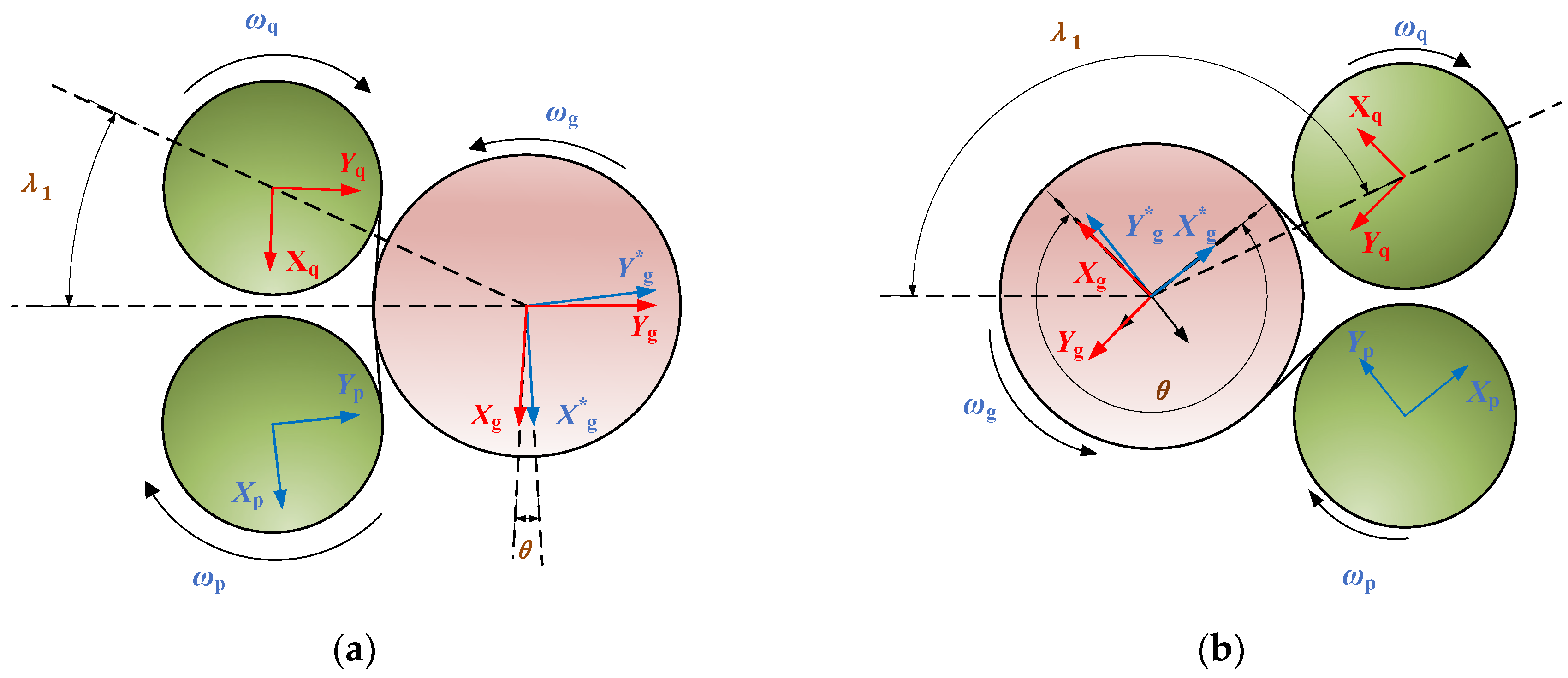
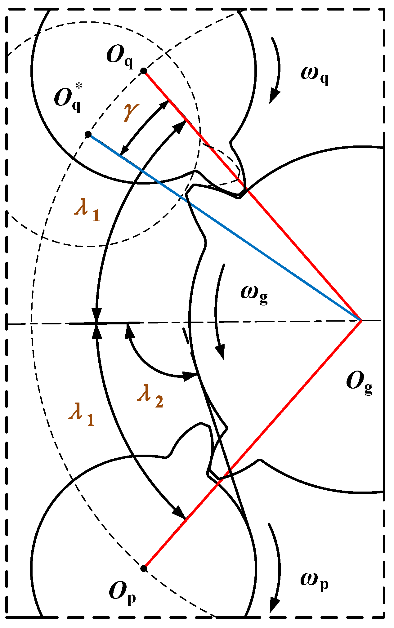
2.1. Analysis of Assembly Angles in the DI-SO Cylindrical Spur Gear System

Taking account of various factors, including production, usage, and maintenance costs, the DI-SO cylindrical spur gear system is designed with interchangeable features. Consequently, the dual-input gear structures are identical. The dual-input and single-output gears are each modeled as lumped parameter systems with rotational and translational degrees of freedom. The dynamic model of the DI-SO cylindrical spur gear system is illustrated in Figure 1. In the figure, p and q represent the upper and lower input gears, and g denotes the output gear. The subscripts p, q, and g correspond to the physical parameters of each respective gear. Based on the meshing line direction, the supporting stiffness and damping of each gear transmission shaft are divided into X and Y axes. The elastic deformation of the meshing pair and support points is characterized by equivalent spring stiffness. Xp, Yp, Xq, Yq, Xg, and Yg represent the coordinate systems of the dual-input and single-output gears. X*g and Y*g denote the auxiliary coordinate system for the single-output gear. Here, Xp is parallel to X*g, Yp is parallel to Y*g, Xq is parallel to Xg, and Yq is parallel to Yg. ωp, ωq, and ωg represent the input and output angular velocities. kpx, kpy, kqx, kqy, kgx, and kgy denote the shaft-bearing stiffness. cpx, cpy, cqx, cqy, cgx, and cgy represent the shaft-bearing damping. Numbers 1 and 2 represent the gear pairs between the dual-input gears and the output gear. If 1 and 2 are used as subscripts, they denote the physical parameters of the corresponding gear pairs. k1(t) and k2(t) present the time-varying meshing stiffness of gear pairs p and q. cm1 and cm2 represent the meshing damping. e1(t) and e2(t) denote the comprehensive transmission error. α denotes the gear-meshing pressure angle. θ denotes the angle between axes Xg and X*g, representing the angle of the auxiliary coordinate transformation. λ1 represents the assembly angle of gear q, which denotes the angle of the line connecting the gear centers and the horizontal line. λ2 is the angle of the meshing line of gear p and the horizontal line.
The bending–torsion coupling vibration analysis model of the DI-SO cylindrical spur gear system has 9 degrees of freedom. The generalized displacement vector D is defined as follows:
D = [ θ p , θ q , θ g , x p , x q , x g , y p , y q , y g ]
among them, θp, θq, and θg represent the torsional displacements of the dual-input and single-output gears; xp, xq, and xg denote the lateral displacements; and yp, yq, and yg represent the longitudinal displacements.
In the design of the DI-SO cylindrical spur gear system, a key parameter is the assembly angle between the dual-input and single-output gears. This angle is considered the adjacent condition for the split transmission of the dual-input cylindrical gear. Figure 2 illustrates the coordinate relationship of the DI-SO cylindrical spur gear system when the assembly angle λ1 is at the maximum and minimum values. The extreme configurations of the gear system are shown as either left-side or right-side arrangements.
Based on the geometric relationship, the mathematical expressions for the minimum assembly angle λ1min and the maximum assembly angle λ1max are obtained as follows:
λ 1 min = arcsin ( R q R q + R g )
λ 1 max = π λ 1 min
where Rq and Rg are the pitch circle radii of the dual-input and single-output gears.
Furthermore, the relationship between the meshing pressure angle α (the standard pressure angle of cylindrical spur gears is π/9), the assembly angle λ1, the angle λ2 of the meshing line and the horizontal line, and the auxiliary coordinate transformation angle θ can be derived:
λ 2 = λ 1 α + π 2
θ = 2 λ 2 π
To ensure a unified coordinate system for the output gear, the dual-input and single-output gears are considered to have equal geometric parameters. The transformation matrix between the primary coordinate system and the auxiliary coordinate system of the output gear is obtained:
( X g Y g ) = ( cos θ sin θ sin θ cos θ ) ( X g Y g )
Moreover, based on the principle of comprehensive transmission error, the DTE xn1 and xn2 are calculated. The vibration displacement relative to the contact line between the tooth surfaces of the dual-input gears is obtained:
{ x n 1 = x p + R bp θ p x g R bg θ g e p ( t ) x n 2 = x q + R bq θ q x g R bg θ g e q ( t )
where Rbp, Rbq, and Rbg represent the base circle radii of the dual-input and single-output gears, and x g denotes the lateral displacement of the auxiliary coordinate system.
The comprehensive transmission error es(t) is a periodic function and is considered an internal factor. This error encompasses all forms of transmission discrepancies, including those caused by various factors, such as gear tooth profile deviations, manufacturing inaccuracies, and operational dynamics like deflections and deformations under load. It can be expressed as:
e s ( t ) = e cos ( ω e t + θ m )
where e represents the error fluctuation term, ωe denotes the meshing frequency, θm is the initial phase angle of the system, and the gear pair s denotes either gear pair p or gear pair q.
Additionally, the meshing frequency of the system can be determined using the following formula:
ω e = 2 π Z p n p 60
among them, Zp is the number of teeth on gear p, and np denotes the rotational speed of gear p.

2.2. Analysis of Meshing Force in the DI-SO Cylindrical Spur Gear System

Although the layout of the DI-SO cylindrical spur gear system is symmetric, the force distribution is asymmetric. The resultant force acting on the output gear is non-zero. Figure 3 illustrates the angular relationship between the coordinate axes of different gears in the DI-SO cylindrical spur gear system, as well as the schematic distribution of the normal meshing load between the dual-input and single-output gears. In the figure, Tp, Tq, and Tg represent the input and output torque of the input and output gears. Fn1 and Fn2 are the meshing force of the direction of the meshing line. Ffp and Ffq denote the friction force acting orthogonally to the meshing line.
The normal load between the meshing tooth surfaces is:
F n i = K s ( t ) f ( x n i ) + c m i x ˙ n i
The function f(xni) represents the backlash and is expressed as:
f ( x n i ) = { x n i b , x n i > b 0 , b x n i b x n i + b , x n i b
among them, b is defined as half of the mean normal meshing clearance.
Considering the meshing characteristics of the DI-SO cylindrical spur gear system, the initial meshing point is set at the root of the input gear. A reference for determining the initial direction of friction force is established. The initial phase angles of time-varying meshing stiffness, the time-varying friction coefficient, and the load-sharing ratio are determined. A diagram of local meshing in the DI-SO cylindrical spur gear system under the initial meshing condition is illustrated in Figure 4. As shown in Figure 4, points A and E represent the start and end of the double-tooth engagement. Points B and D denote the start and end of the single-tooth engagement. Point P is the meshing point. N1N2 presents the theoretical meshing line of the gear pair. vq, vq, vg, and vg present the velocities of the input and output gears at the meshing point. vgq and vgq are the relative velocities between the output gear and the input gear. According to the gear meshing principle, the gear only exhibits pure rolling meshing at point C, while relative sliding occurs at other meshing positions. Additionally, the relative velocity direction between the tooth surfaces will reverse on either side of point C. Therefore, the direction of the sliding friction force can be governed by the direction of the relative velocity.

2.3. Analysis of Meshing Conditions in the DI-SO Cylindrical Spur Gear System

Because of the layout constraints of the DI-SO cylindrical spur gear system, the engagement process of the dual gear pairs is challenging to fully synchronize. To ensure meshing transmission between the gear pairs, a symmetrical layout structure is adopted for the dual-input gears. However, the tooth profile is not symmetric. As shown in Figure 5, when the assembly angle is λ1, the initial meshing point is located at the root of the input gear p. In the figure, Op and Og denote the actual assembly centers of the input and output gears. Oq is the actual assembly center of the input gear q. The initial meshing point is not located at the tooth root, resulting in a phase difference in meshing stiffness. However, O*q represents the ideal assembly center. The initial meshing point is located at the tooth root, resulting in no phase difference in meshing stiffness. There may be a difference in the number of teeth on the output gear between ∠OpOgO*q and ∠OpOgOq. The former is an integer, while the latter may be a non-integer. γ represents the difference between these two angles, reflecting the disparity in the number of teeth. Thus, the phase and time differences in the meshing stiffness of the dual-gear pairs at the actual assembly angle are analyzed:
γ = | λ 1 Z g π λ 1 Z g π |
φ = ω e 2 π γ Z g ω g
Δ t = 2 π γ Z g ω g
among them, Zg is the number of teeth on gear g, and ⌊ ⌋ represents the floor function (integer value), which returns the greatest integer less than or equal to the value within the bracket.
Based on traditional empirical design methods, practitioners often encounter the issue of whether the gears need to be synchronized when handling the assembly angle. The impact of different but close assembly angles on the gear system needs to be further assessed. It must be determined whether the number of teeth on the output gear between ∠OpOgOq is an integer. Therefore, further investigation is needed to explore the differences in the DI-SO cylindrical spur gear system under synchronous and asynchronous meshing conditions. Based on the bifurcation characteristics of the assembly angle, the assembly angle λ1 is determined to be an acute angle in this research. The system maintains stable periodic motion to the greatest extent possible, and the dynamic characteristics are effectively reflected. Specifically, an assembly angle of 0.523 rad is selected, which corresponds to the asynchronous meshing condition of the DI-SO cylindrical spur gear system. According to Equation (14), an assembly angle of 0.514 rad is obtained, which corresponds to the synchronous meshing condition. Under these assembly angles and meshing conditions, the dynamic characteristics of the DI-SO cylindrical spur gear system are compared in detail.
λ 1 = λ 1 γ Z g 4 π
where λ 1 is defined as the assembly angle of the DI-SO cylindrical spur gear system under the synchronous meshing condition.

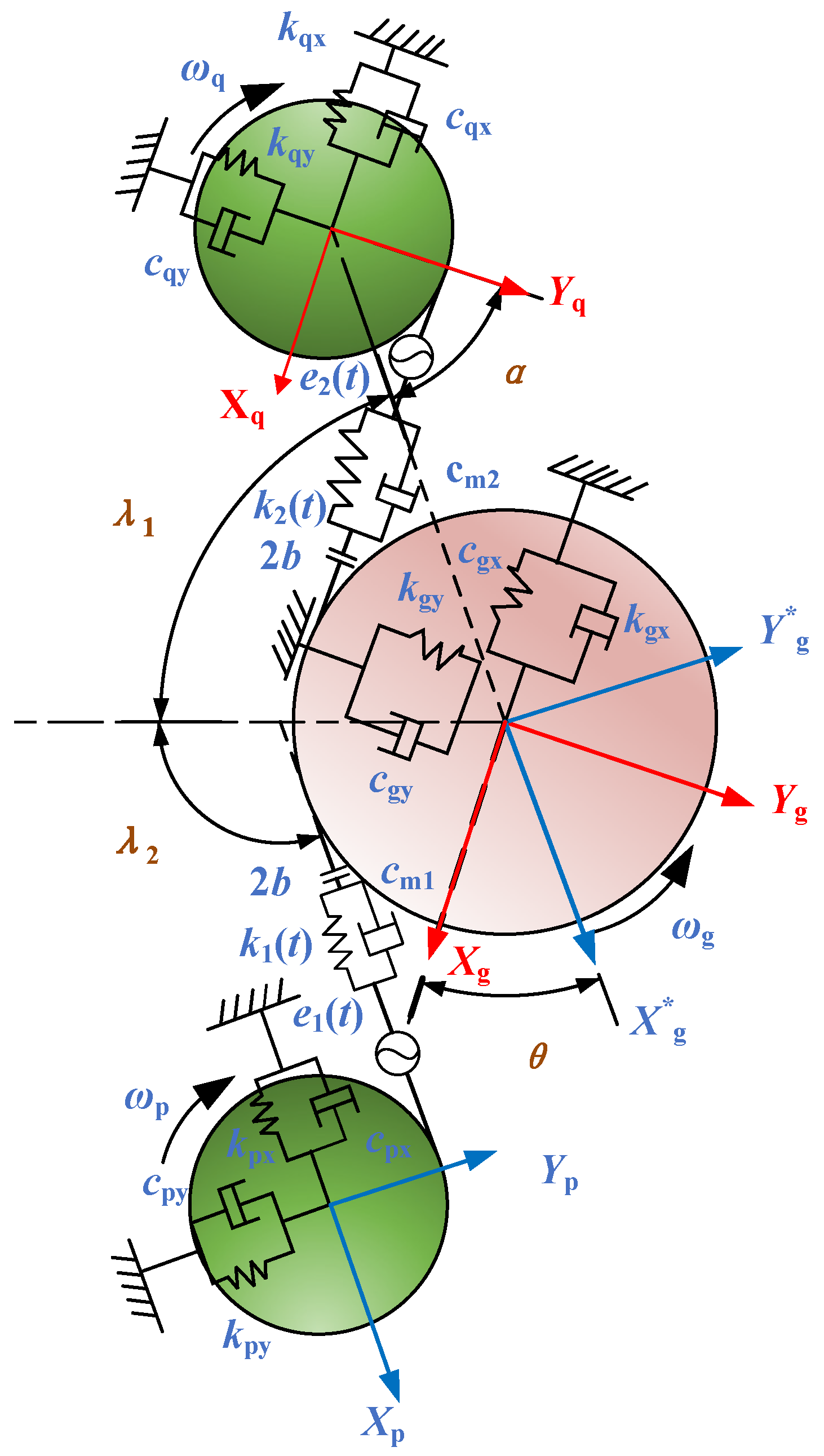
3. Dynamic Modeling of the DI-SO Cylindrical Spur Gear System

3.1. Mathematical Description of Time-Varying Parameters

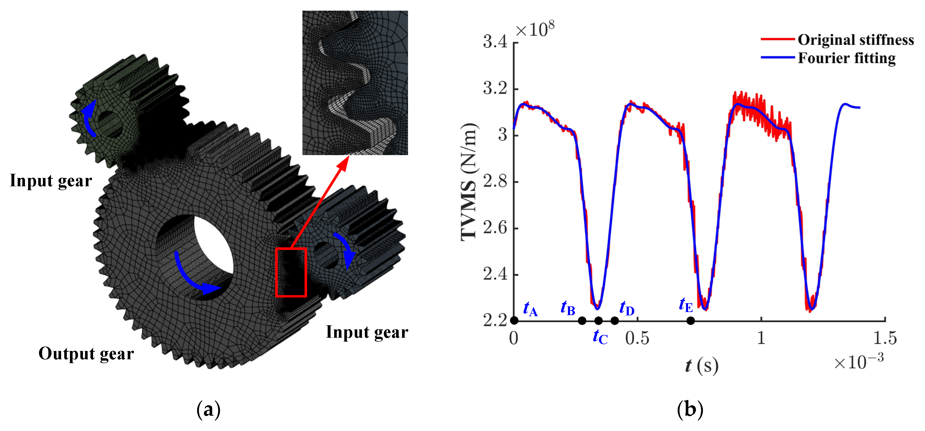
3.1.1. Time-Varying Meshing Stiffness

The nonlinear dynamic characteristics of the DI-SO cylindrical spur gear system are significantly influenced by the periodic variation in gear meshing stiffness. Currently, various methods for calculating time-varying meshing stiffness have been researched by scholars, including the Ishikawa method and the Weber method. These studies mostly focus on the analysis of a single gear pair. In Figure 6a, the DI-SO cylindrical spur gear system is chosen as the research subject. The gear model is imported into Workbench. Subsequently, the relative rotational angle data between the input and output gears are obtained based on the quasi-static algorithm. Further, the time-varying meshing stiffness is thoroughly calculated and analyzed [33].
Significant periodic variations in the meshing stiffness are observed. Figure 6b illustrates the time-varying meshing stiffness of the DI-SO cylindrical spur gear system under the initial meshing condition. According to Equation (12), under the asynchronous meshing condition, there is a phase difference in the meshing processes. The time-varying meshing stiffness is obtained through Fourier series expansion using Matlab R2022b. The harmonic parameters of the first three orders of approximate stiffness are listed in Table 1.
K p ( t ) = k m + j = 1 k j cos ( j ω e t + ϕ j )
K q ( t ) = k m + j = 1 k j cos ( j ω e t + ϕ j + φ )
where km denotes the average meshing stiffness, and ϕj presents the phase angle of each harmonic.

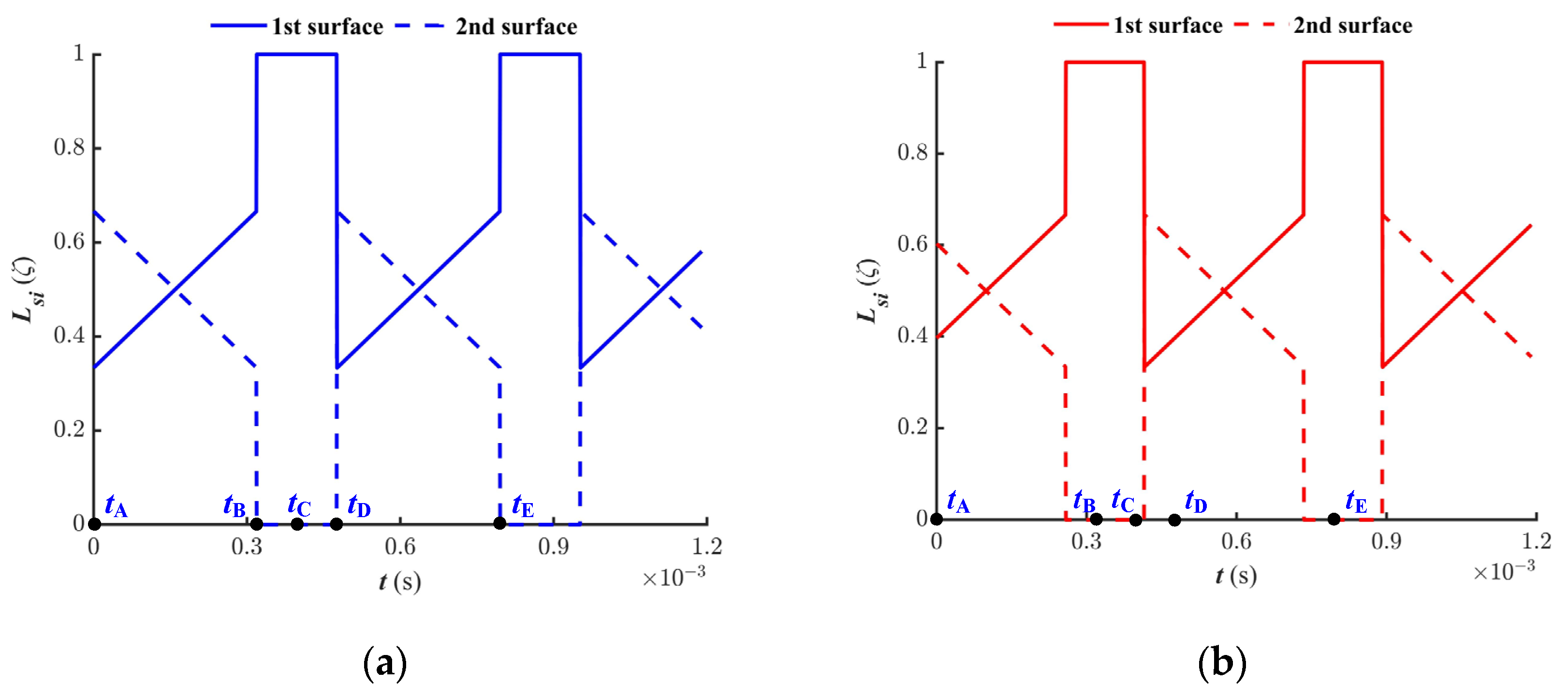
3.1.2. Load-Sharing Ratio

The variation in the load-sharing ratio is directly determined by the contribution of the meshing force. The nonlinear behavior of the DI-SO cylindrical spur gear system is significantly affected. Based on the results from the literature, the load-sharing ratio is integrated into the model analysis. Under the condition of gear meshing, it is represented as [34]:
L ( ζ ) = { 1 3 ( 1 + ζ C ( t ) ζ A ζ D ζ A 1 ) ( ζ A ζ C ( t ) ζ D 1 ) 1 ( ζ D 1 ζ C ( t ) ζ A + 1 ) 1 3 ( 1 + ζ C ( t ) ζ D ζ A ζ D + 1 ) ( ζ A + 1 ζ C ( t ) ζ D )
where ζA, ζC, and ζD are the profile parameters, and their calculation formulas are referenced from [34].
Due to the meshing point being located at the root of the input gear tooth, a phase difference exists in the gear meshing. Figure 7 illustrates the load-sharing ratio during the double → single → double tooth meshing process. To enhance the clarity of the analysis, the time points corresponding to the A, B, C, D, and E nodes during the gear-meshing process are labeled in the figure. The meshing force of the i-th tooth surface of gear pair s is given by:
F s m i = L si ( ζ ) F n i
among them, s represents p or q.
The meshing force Fsm1 acts continuously on a single tooth surface, whereas the meshing force Fsm2 occurs exclusively during double-tooth meshing.

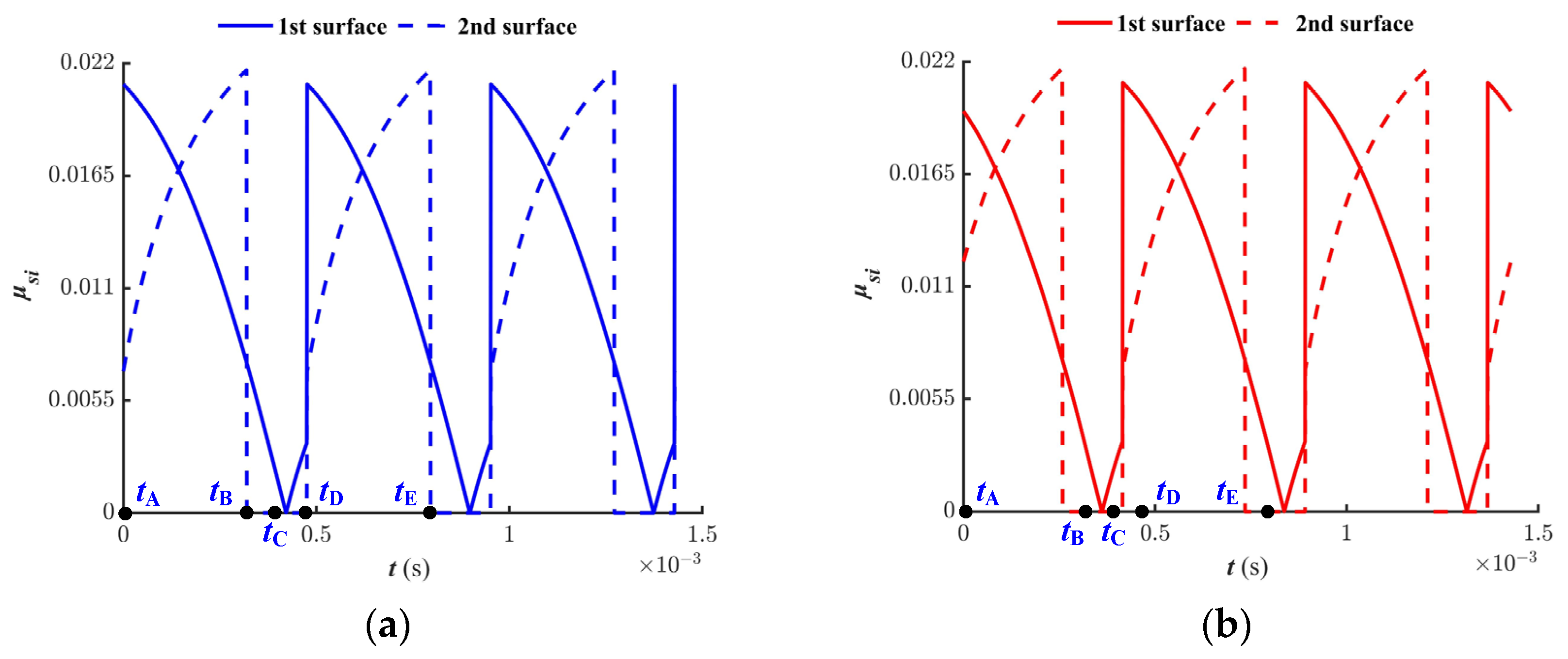
3.1.3. Time-Varying Friction

The friction force acts perpendicular to the contact line. The dynamic friction force and torque are controlled by multiple parameters, including the sliding velocity at the contact point, rolling velocity, instantaneous load, and properties of the lubricant. According to the theory of elastohydrodynamic lubrication, Xu proposes a calculation model for the friction coefficient [35]:
{ μ i = e f ( S R φ , P φ , v 0 , S ) P φ b 2 | S R φ | b 3 υ e φ b 6 v 0 b 7 R φ b 8 f ( S R φ , P φ , v 0 , S ) = b 1 + b 4 | S R φ | P φ lg ( v 0 ) + b 5 e | S R φ | P φ lg ( v 0 ) + b 9 e S
where μi represents the friction coefficient (μ1 represents the coefficient of double-tooth meshing, and μ2 represents the coefficient of single-tooth meshing), SRφ denotes the rolling–sliding ratio, Pφ is the Hertzian pressure, v0 is the absolute viscosity, S is the surface roughness, veφ represents the rolling speed, Rφ is the effective curvature radius, and b1~b9 represent the multiple linear regression coefficient. The parameter values and calculation formulas are referenced from [21,35].
It is confirmed that the initial contact point is located at the tooth root of the input gear p. The meshing point shifts from the root to the tip of the input gear tooth. There is an alternating meshing phenomenon between single-tooth and double-tooth. Due to the relative sliding between the tooth surfaces, sliding friction force is generated. As shown in Figure 4, the direction of the sliding friction at point C is observed to reverse. Thus, the directional coefficient of friction λpi is introduced for the gear pair p:
λ p 1 = { 1 ( 0 < t < t C ) 1 ( t C < t < T )
λ p 2 = { 1 ( 0 < t < t B ) 1 ( t B < t < T )
among them, tC represents the time taken for meshing from the tooth root to point C within one meshing cycle, T denotes the meshing cycle, and tB indicates the duration of the double-tooth meshing state within a single meshing cycle T.
Due to the initial condition, a phase difference exists between the gear pairs. As revealed in Figure 8, the time-varying friction coefficient during alternating single-tooth and double-tooth meshing are illustrated. The friction force on the i-th tooth surface of the gear pair s is calculated by:
F f s i = μ si λ si F s m i
When the gear is in an alternating single-tooth and double-tooth meshing state, the friction force Ffs1 continuously acts on the first tooth surface. However, during the single-tooth meshing phase, the second tooth surface experiences separation, and the friction coefficient μs2 is zero. Therefore, the friction force Ffs2 occurs exclusively during the double-tooth meshing. The total sliding friction force of the gear pair s is calculated as:
F f s = F f s 1 + F f s 2
Additionally, the friction arms and the time-varying coefficient are subjected to periodic variations with the meshing position. The friction arms can be calculated based on the geometric relationship [36]:
S s 1 = a 2 ( R b s + R bg ) 2 R ag 2 R bg 2 + R b s ω s t
S s 2 = a 2 ( R b s + R bg ) 2 R ag 2 R bg 2 + R b s ω s t + P b
S g 1 s = R ag 2 R bg 2 R b s ω s t
S g 2 s = R ag 2 R bg 2 R b s ω s t P b
among them, a represents the center distance between the dual-input and single-output gears; Ss1, Ss2, Sgs1, and Sgs2 are the friction arms at the meshing points of the input gear s and output gear g; Pb presents the base circle pitch; and Rag denotes the radius of the pitch circle of the output gear. According to Equation (13), if the gears are in the asynchronous meshing condition, a time difference exists in the variation of the gear force arms of the driving gears p and q.

3.2. The Dynamic Equations of the DI-SO Cylindrical Spur Gear System

The analysis model of the DI-SO cylindrical spur gear system, the meshing force analysis, and different meshing conditions are considered. The dynamic equations of the bending–torsion coupling vibration analysis model of the generalized displacement vectors are established:
{ m p x ¨ p + c px x ˙ p + k px x p = F n 1 m q x ¨ q + c qx x ˙ q + k qx x q = F n 2 m g x ¨ g + c gx x ˙ g + k gx x g = F n 1 cos θ + F n 2 + F fp sin θ m p y ¨ p + c py y ˙ p + k py y p = F fp m q y ¨ q + c qy y ˙ q + k qy y q = F fq m g y ¨ g + c gy y ˙ g + k gx y g = F n 1 sin θ + F fq F fp cos θ I p θ ¨ p = T p R bp F n 1 + ( F fp 1 S p 1 + F fp 2 S p 2 ) I q θ ¨ q = T q R bq F n 2 + ( F fq 1 S q 1 + F fq 2 S q 2 ) I g θ ¨ g = T g + R bg F n 1 + R bg F n 2 ( F fp 1 S g 1 p + F fp 2 S g 2 p ) ( F fq 1 S g 1 q + F fq 2 S g 2 q )
where mp, mq, and mg are the concentrated masses of the dual-input and single-output gears, and Ip, Iq, and Ig denote the moments of inertia.
Additionally, the mesh damping cm1 is proportional to the average meshing stiffness km, and can be obtained using the empirical formula below [37]:
c m 1 = 2 ζ c k m R p 2 R g 2 I p I g I g R g 2 + I p R p 2
among them, ζc denotes meshing damping coefficient, and Rp presents the pitch circle radius of the input gear. cm2 is the same as above.
The model primarily focuses on the dynamic meshing coupling of spur gear pairs, and it does not account for the specific vibration modes of the shafts and bearings. To simplify the analysis, the support damping, incorporating contributions from the shafts and bearings, is consolidated into equivalent values. The support damping cpx can be obtained as [38]:
c px = 2 ξ k k px m p
where ξk presents support damping coefficient. cpx, cqx, cgx, cpy, cqy, and cgy are the same as above.

4. Nonlinear Dynamic Characteristics of the DI-SO Cylindrical Spur Gear System under Different Meshing Conditions

The previously established bending–torsion coupling vibration model of the DI-SO cylindrical spur gear system is analyzed using numerical computation methods. The fourth–fifth order Runge–Kutta numerical analysis method of the adaptive variable step is employed to ensure the accuracy and stability of the solution process. The design parameters are displayed in Table 2. Under different assembly angles, external excitations such as meshing frequency and driving load fluctuation, as well as internal nonlinear factors such as comprehensive transmission error and backlash, are thoroughly analyzed. The dynamic behavior of the DI-SO cylindrical spur gear system is studied through various nonlinear dynamic analysis methods.

4.1. The Influence of Meshing Frequency on the Dynamic Characteristics of the DI-SO Cylindrical Spur Gear System

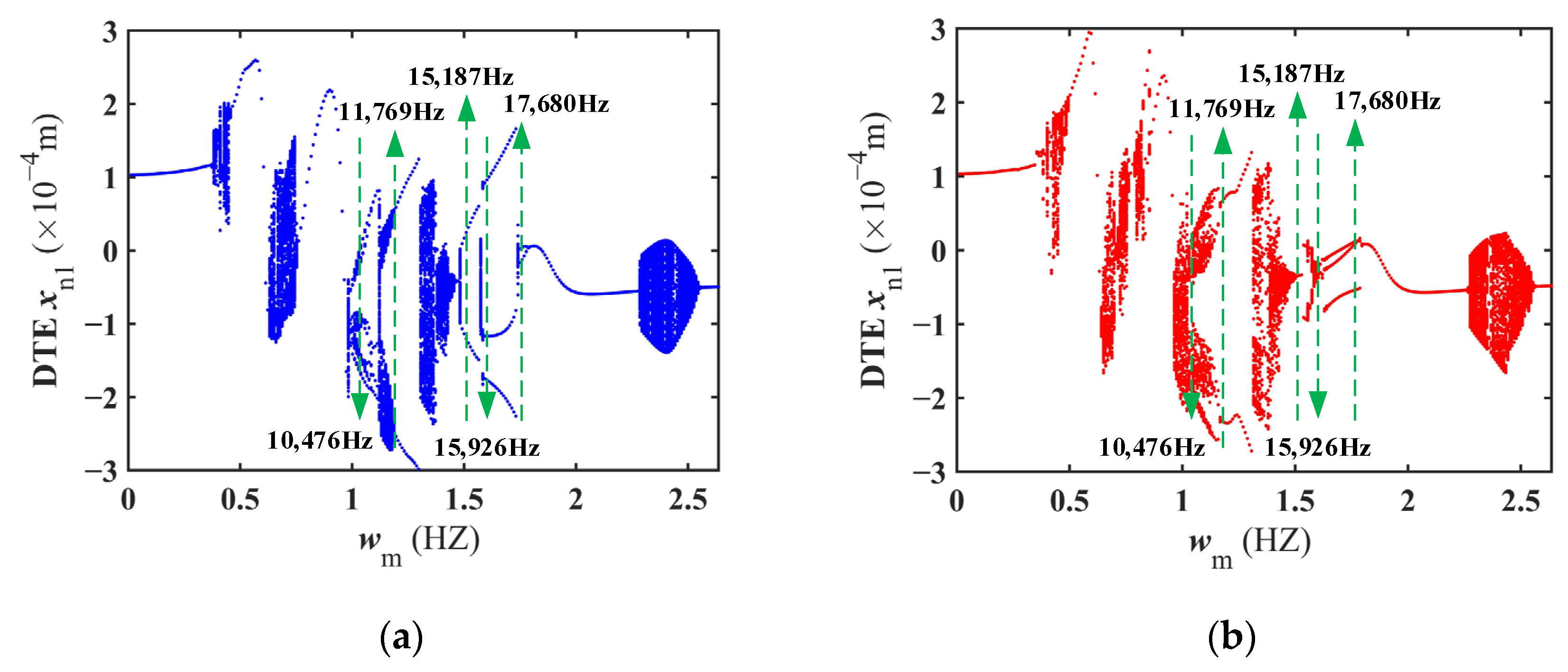
4.1.1. Bifurcation Characteristics of Meshing Frequency

The meshing frequency is identified as a key internal excitation parameter influencing the dynamic characteristics. It is reflected by the rotational speeds of the input and output gears [39]. As the rotational speed increases (1~200 r/s), the meshing frequency wm varies from 0 to 2.63 × 10⁴ Hz. The bifurcation diagram is utilized as a crucial tool for studying nonlinear dynamic behavior. By using the meshing frequency as a control parameter, the dynamic response of the DI-SO cylindrical spur gear system is analyzed within the range of 0 to 2.63 × 10⁴ Hz. The bifurcation diagram of the DTE is shown in Figure 9 under different assembly angles and meshing conditions.
As presented in Figure 9a, the bifurcation characteristics of the DI-SO cylindrical spur gear system under the synchronous meshing condition are presented. Firstly, when the meshing frequency wm ˂ 0.37 × 10⁴ Hz, the DI-SO cylindrical spur gear system remains in a single-periodic motion state. When 0.36 × 10⁴ ˂ wm ˂ 0.46 × 10⁴ Hz, the DI-SO cylindrical spur gear system transitions abruptly to a chaotic motion state. When 0.46 × 10⁴ ˂ wm ˂ 0.62 × 10⁴ Hz, the DI-SO cylindrical spur gear system returns to a single-periodic motion state. When 0. 62 × 104 ˂ wm ˂ 0. 78 × 104 Hz, the DI-SO cylindrical spur gear system enters a chaotic motion state. When 0.78 × 10⁴ ˂ wm ˂ 0.96 × 10⁴ Hz, chaotic motion disappears, and the DI-SO cylindrical spur gear system returns to a single-periodic motion state. Next, when 0.96 × 10⁴ ˂ wm ˂ 1.19 × 10⁴ Hz, the gear system shifts from a brief multi-periodic motion state to a quasi-periodic motion. state. When 1.19 × 10⁴ ˂ wm ˂ 1.31 × 10⁴ Hz, the DI-SO cylindrical spur gear system enters a double-periodic motion state. When 1.31 × 10⁴ ˂ wm ˂ 1.46 × 10⁴ Hz, the DI-SO cylindrical spur gear system again transitions to a chaotic motion state. When 1.46 × 10⁴ ˂ wm ˂ 1.58 × 10⁴ Hz, the DI-SO cylindrical spur gear system transitions to a double-periodic motion state. Subsequently, when 1.58 × 10⁴ ˂ wm ˂ 1.73 × 10⁴ Hz, the DI-SO cylindrical spur gear system bifurcates from a double-periodic to a triple-periodic motion state. When 1.73 × 10⁴ ˂ wm ˂ 1.78 × 10⁴ Hz, the DI-SO cylindrical spur gear system returns to a double-periodic motion state. When 1.78 × 10⁴ ˂ wm ˂ 2.27 × 10⁴ Hz, the DI-SO cylindrical spur gear system transitions to a stable single-periodic motion state. When 2.27 × 10⁴ ˂ wm ˂ 2.55 × 10⁴ Hz, the DI-SO cylindrical spur gear system transitions to a quasi-periodic motion state. When the meshing frequency wm exceeds 2.55 × 10⁴ Hz, the DI-SO cylindrical spur gear system transitions back to a single-periodic motion state.
The bifurcation characteristics of the DI-SO cylindrical spur gear system under the asynchronous meshing condition are illustrated in Figure 9b. Firstly, when the meshing frequency wm is less than 0.35 × 10⁴ Hz, the DI-SO cylindrical spur gear system transitions to a single-periodic motion state. When 0.35 × 10⁴ ˂ wm ˂ 0.50 × 10⁴ Hz, the DI-SO cylindrical spur gear system transitions abruptly to a chaotic motion state. When 0.50 × 10⁴ ˂ wm ˂ 0.62 × 10⁴ Hz, the DI-SO cylindrical spur gear system transitions to a single-periodic motion state. When 0. 62 × 104 ˂ wm ˂ 0. 92 × 104 Hz, the DI-SO cylindrical spur gear system enters a chaotic motion state. When 0.92 × 10⁴ ˂ wm ˂ 0.96 × 10⁴ Hz, the chaotic motion disappears, and the DI-SO cylindrical spur gear system returns to a single-periodic motion state. Next, when 0.96 × 10⁴ ˂ wm ˂ 1.01 × 10⁴ Hz, the DI-SO cylindrical spur gear system transitions to a chaotic motion state. When 1.01 × 10⁴ ˂ wm ˂ 1.17 × 10⁴ Hz, the DI-SO cylindrical spur gear system enters an approximate double-periodic motion state. When 1.17 × 10⁴ ˂ wm ˂ 1.31 × 10⁴ Hz, the DI-SO cylindrical spur gear system stabilizes and transitions to a double-periodic motion state. When 1.31 × 10⁴ ˂ wm ˂ 1.50 × 10⁴ Hz, the DI-SO cylindrical spur gear system transitions to a chaotic motion state. When 1.50 × 10⁴ ˂ wm ˂ 1.52 × 10⁴ Hz, the DI-SO cylindrical spur gear system transitions to a brief single-periodic motion state. When 1.52 × 10⁴ ˂ wm ˂ 1.61 × 10⁴ Hz, the DI-SO cylindrical spur gear system transitions to a chaotic motion state again. When 1.61 × 10⁴ ˂ wm ˂ 1.78 × 10⁴ Hz, the DI-SO cylindrical spur gear system bifurcates from a double-periodic to a triple-periodic motion state. Subsequently, when 1.78 × 10⁴ ˂ wm ˂ 2.26 × 10⁴ Hz, the DI-SO cylindrical spur gear system returns to a stable single-periodic motion state. When 2.26 × 10⁴ ˂ wm ˂ 2.56 × 10⁴ Hz, the DI-SO cylindrical spur gear system enters a quasi-periodic motion state. When the meshing frequency wm exceeds 2.56 × 10⁴ Hz, the DI-SO cylindrical spur gear system transitions back to a single-periodic motion state.
To facilitate description, the range of 0 ˂ wm ˂ 0.96 × 10⁴ Hz is defined as the low-frequency meshing stage, 0.96 × 10⁴ ˂ wm ˂ 1.78 × 10⁴ Hz is defined as the medium-frequency meshing stage, and 1.78 × 10⁴ ˂ wm ˂ 3 × 10⁴ Hz is defined as the high-frequency meshing stage. By comparison, at the low-frequency meshing stage, whether under the synchronous or asynchronous meshing condition, the bifurcation diagrams of the DI-SO cylindrical spur gear system present a generally consistent vibration response. They exhibit a rich array of nonlinear dynamic behaviors. The systems sequentially experience states of single-periodic → chaos → single-periodic → chaos → single-periodic → chaos motion. At the medium-frequency meshing stage, complex and irregular bifurcation phenomena are experienced. However, the specific motion states differ. Especially under the asynchronous meshing condition, a longer duration of the chaotic motion state is observed. The system is unstable and unpredictable. Subsequently, at the high-frequency meshing stage, the systems undergo transitions involving single-periodic → chaotic → single-periodic motion states. Overall, there is a significant impact of the nonlinear dynamic behaviors at the medium-frequency meshing stage. Therefore, the dynamic characteristics within this stage must be thoroughly studied.

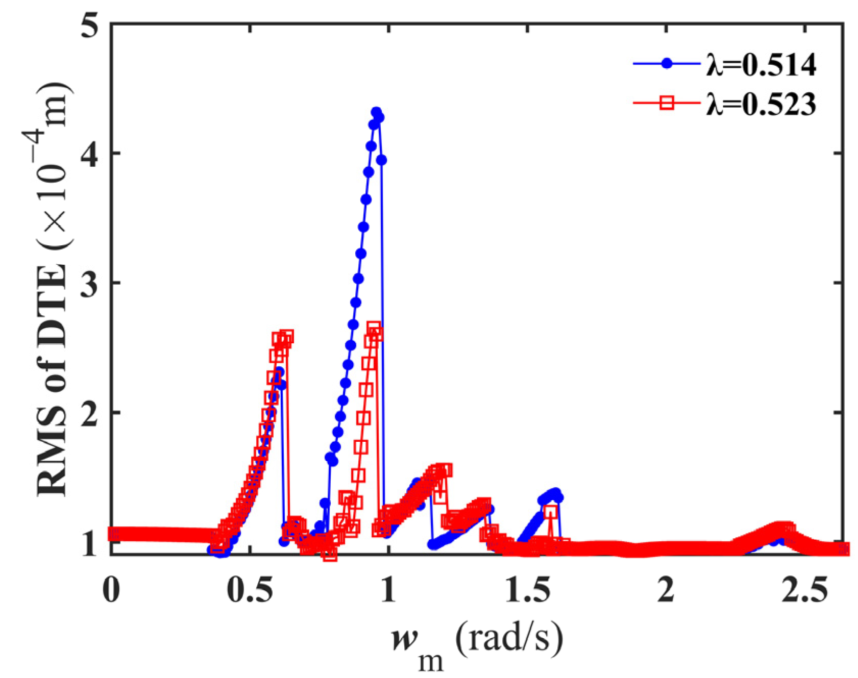
4.1.2. RMS of DTE Vibration Response with Meshing Frequency

The performance of the DI-SO cylindrical spur gear system is significantly affected by the dynamic characteristics. Using the frequency sweep diagram, the RMS of the DTE is analyzed under synchronous and asynchronous meshing conditions in this section [40]. As presented in Figure 10, the primary results are summarized: (1) There are significant jumps at different meshing frequencies, whether under the synchronous or asynchronous meshing condition. Under the synchronous meshing condition, the jump phenomena are observed at frequencies of 6043 Hz, 9552 Hz, 11492 Hz, 13,616 Hz, and 16,018 Hz. Under the asynchronous meshing condition, the jump phenomena are observed at frequencies of 6320 Hz, 9460 Hz, 12,046 Hz, 13,432 Hz, and 15,833 Hz. (2) There is a significant difference in the RMS of the DTE under synchronous and asynchronous meshing conditions during the low-frequency meshing stage. Within the meshing frequency range of 6412 Hz to 9737 Hz, there is a 55.8% increase in the maximum DTE of the synchronized gear system compared to the maximum DTE in the asynchronized gear system. Significant jumping phenomena in the DTE are exhibited under the synchronous meshing condition. Gear disengagement is quite severe, which can lead to gear separation and result in impact. Severe vibration is experienced by the synchronized gear system. (3) The jumping phenomena are primarily concentrated in the medium-frequency meshing stage. Outside the 6412 Hz to 9737 Hz frequency range, the DTE of the asynchronized gear system is generally slightly higher than that of the asynchronized gear system. However, the variation patterns are similar. Additionally, the presence of consistent hardening behavior can be attributed to the specific configuration of the gear system, which includes two input gears. This dual-input setup, combined with the intense condition of the backside contact, makes it challenging for a complete separation between the input and output gears to occur. The resulting hardening behavior overshadows the softening behavior that arises from the tooth separation. In summary, the meshing conditions should be appropriately selected to accommodate different meshing frequencies. This approach helps to reduce the DTE amplitude and eliminate gear tooth separation, impact, and collision.

4.1.3. Nonlinear Dynamic Behavior at the Medium-Frequency Meshing Stage

Under synchronous and asynchronous meshing conditions, the differences in the dynamic characteristics in the DI-SO cylindrical spur gear system need to be further studied. In this section, the key frequencies at the medium-frequency meshing stage are analyzed in detail by using time history diagrams and Phase–Poincaré maps. In Figure 9, five key frequencies are marked with green dashed lines: 10,476 Hz, 11,769 Hz, 15,187 Hz, 15,926 Hz, and 17,680 Hz. The dynamic responses at these frequencies are compared, as shown in Figure 11.
When wm = 10476 Hz, the time–domain response of the DI-SO cylindrical spur gear system under the synchronous meshing condition is characterized by a multi-periodic subharmonic vibration response (8T). The phase map exhibits a closed curve with multiple cycles. Eight discrete fixed points are observed in the Poincaré section. The system exhibits multi-periodic motion. The time–domain response of the DI-SO cylindrical spur gear system under the asynchronous meshing condition is characterized by a chaotic vibration state. The phase map is composed of intertwined and intersecting closed curves. The Poincaré section displays an infinite number of discrete points. The system enters a chaotic motion state.
When wm = 11,769 Hz, the time–domain response of DI-SO cylindrical spur gear system under the synchronous meshing condition is characterized by an approximately periodic vibration state. The phase map displays closed curves with multiple cycles that do not intersect. The discrete points form a closed curve in the Poincaré section. The system exhibits a quasi-periodic motion. The time–domain response of the DI-SO cylindrical spur gear system under the asynchronous meshing condition is characterized by a stable double-periodic subharmonic vibration response (2T). The phase map trajectory is depicted as a closed curve with two cycles. Two discrete fixed points are presented by the Poincaré section. The system enters a double-periodic motion state.
When wm = 15,187 Hz, the time–domain response of the DI-SO cylindrical spur gear system under the synchronous meshing condition is characterized by a stable double-periodic subharmonic vibration response (2T). The trajectory lines in the phase map are represented by closed curves with two cycles of winding. The Poincaré section shows two discrete fixed points. The system exhibits a double-periodic motion. The time–domain response of the DI-SO cylindrical spur gear system under the asynchronous meshing condition is characterized by a stable single-periodic vibration response (T). The phase map trajectory forms a single-loop closed curve. A single discrete fixed point is represented in the Poincaré section. The system transitions to a single-periodic motion state.
When wm = 15,926 Hz, the time–domain response of the DI-SO cylindrical spur gear system under the synchronous meshing condition is characterized by a stable triple-periodic subharmonic vibration response (3T). On the phase map, the trajectory line forms a closed curve with three winding cycles. The Poincaré section displays three discrete fixed points. The system transitions to a triple-periodic motion state. The time-domain response of the DI-SO cylindrical spur gear system under the asynchronous condition is characterized by a disordered vibration state. The phase map is composed of intertwining and crossing curves. The Poincaré section shows an infinite number of discrete points. The system enters a chaotic motion state.
When wm = 17,680 Hz, the time–domain responses of the DI-SO cylindrical spur gear systems under synchronous and asynchronous meshing conditions are characterized by a double-periodic subharmonic vibration response (2T). The phase map trajectory forms a closed curve with two winding cycles. The Poincaré section presents two discrete fixed points. The system transitions to a double-periodic motion state.
Based on the above analysis, there is a significant impact of different meshing conditions on the dynamic characteristics at the medium-frequency meshing stage. The DI-SO cylindrical spur gear system not only exhibits varying DTE values and vibration periods but also demonstrates complex nonlinear dynamic behaviors. From an engineering perspective, adjusting gear-meshing conditions improves the stability of the gear system. The duration of chaotic motion state is reduced. Additionally, by optimizing rotational speed and adjusting the meshing frequency, the system strives to maintain a periodic motion state as much as possible. Ultimately, the noise and uncontrollable vibration are effectively reduced.

4.2. The Impact of Meshing Frequency on the Dynamic Characteristics of the DI-SO Cylindrical Spur Gear System

In the previous section, the differences in dynamic performance of the cylindrical spur gear system at different meshing frequencies were analyzed. However, the complexity of the system is closely associated with the diversity of various excitations [41]. Therefore, the effects of external excitations and internal factors, including driving load fluctuation, backlash, and comprehensive transmission error, on the dynamic characteristics will be explored. Among them, the control parameter for the comprehensive transmission error is the fluctuation component e, as shown in Equation (8). By adjusting this fluctuation component, the impact of the time-varying characteristics of the comprehensive transmission error on the dynamic stability and performance can be further evaluated. Additionally, due to differences in the characteristics of the prime mover, load, and other system components, the drive load typically exhibits fluctuations. These fluctuations may be caused by external excitations or dynamic changes, such as speed variations, inertia effects, or unbalanced torques. To simplify calculations and effectively analyze the dynamic behavior, the drive torque load Tp(t) is typically divided into two components: a continuously output average component Tp and a periodic driving load fluctuation Tf cos(ωet). It can be expressed as:
T p ( t ) = T p + T f cos ( ω e t )
There is a significant impact on the dynamic characteristics with controlling parameters, including driving load fluctuation, backlash, and comprehensive transmission error. By adjusting these control parameters, specific dynamic characteristics can be observed under different meshing conditions: (1) The bifurcation characteristics of the DI-SO cylindrical spur gear systems with varying driving load fluctuation are displayed in Figure 12a,b. Regardless of the synchronous or asynchronous meshing condition, the motion state is stabilized as the driving load fluctuation increases. (2) The bifurcation characteristics with varying backlash are presented in Figure 13a,b. As the backlash increases, the gear systems exhibit unstable motion. (3) The impact of comprehensive transmission error on the bifurcation characteristics is exhibited in Figure 14a,b. The DI-SO cylindrical spur gear systems experience periodic, multi-periodic, quasi-periodic, and chaotic motion states under different meshing conditions. Overall, the dynamic characteristics are generally consistent under different meshing conditions. From an engineering application perspective, the periodic motion state is crucial for reducing system vibration and noise. Therefore, the rotational speed and backlash need to be adjusted, and driving load fluctuation and comprehensive transmission error need to be controlled. This method can effectively enhance system performance and extend system life.
There are differences in the influence of various excitations on the bifurcation characteristics of the DI-SO cylindrical spur gear systems within specific frequency ranges: (1) From the comparison of the results in Figure 12a,b, when the load fluctuation range of the input gear p is 0 ˂ Tf ˂ 179 N, the synchronized gear system experiences chaotic → multi-periodic → single-periodic motion states. In contrast, the asynchronized gear system gradually transitions from multi-periodic to single-periodic motion states. (2) Analyzing Figure 13a,b, when the backlash range is 0.8 × 10⁻⁴ ˂ b ˂ 0.9 × 10⁻⁴ m, the synchronized gear system transitions solely from a double-periodic state to chaotic motion. The asynchronized gear system experiences double-periodic → quadruple-periodic → chaotic motion states. (3) As shown in Figure 14a,b, when the comprehensive transmission error range is 7.9 × 10⁻⁴ ˂ e ˂ 9.4 × 10⁻⁴ m, the synchronized gear system transitions from chaotic to double-periodic motion states. The asynchronized gear system encounters chaotic → six-periodic → double-periodic motion states. Clearly, the dynamic performance of the synchronized gear system is more stable compared to those of the asynchronized gear system. Synchronized meshing reduces the dynamic meshing vibration amplitude. Therefore, when addressing gear vibration and noise issues, the impact of meshing conditions and various excitations must be thoroughly considered.

5. Conclusions

In this research, the analysis models of synchronized and asynchronized DI-SO cylindrical spur gear systems are established. The bifurcation characteristics, the RMS of the DTE at the meshing frequency, and the nonlinear dynamic behavior at the medium-frequency meshing stage are investigated. Additionally, the impact of meshing frequency, driving load fluctuation, backlash, and comprehensive transmission error on the dynamic characteristics is analyzed. The main conclusions can be outlined as:
(1) The dynamic performances of the DI-SO cylindrical spur gear system within the meshing frequency range of 0 to 2.63 × 10⁴ Hz (1 to 200 r/s) are analyzed. It is found that the meshing frequency significantly influences the dynamic characteristics of the system as an internal excitation parameter. Under synchronous and asynchronous meshing conditions, the systems alternate between various dynamic responses, including single-periodic, double-periodic, quasi-periodic, and chaotic motion states. The overall trend of these changes is generally consistent. At the medium-frequency meshing stage (0.96 × 10⁴~1.78 × 10⁴ Hz), complex and irregular bifurcation phenomena are experienced by the systems under different meshing conditions. However, the specific motion states are different. Especially within the meshing frequency range of 0.96 × 10⁴~1.16 × 10⁴ Hz, a prolonged chaotic motion state is observed in the asynchronized gear system.
(2) There are jumping phenomena of the RMS of the DTE in the DI-SO cylindrical spur gear systems under different meshing conditions. Under the synchronous meshing condition, the jumping frequencies include 6043 Hz, 9552 Hz, 11,492 Hz, 13,616 Hz, and 16,018 Hz. Under the asynchronous meshing condition, the jumping frequencies include 6320 Hz, 9460 Hz, 12,046 Hz, 13,432 Hz, and 15,833 Hz. Secondly, within the medium-frequency meshing stage, the synchronized gear system exhibits significant jumping phenomena between 6412 Hz and 9737 Hz. The disengagement phenomenon of the gear pair is more pronounced, which may lead to severe vibration. At the medium-frequency meshing stage (0.96 × 10⁴ to 1.78 × 10⁴ Hz), the jumping phenomena are notably concentrated. The DTE in the asynchronized gear system is generally higher than the DTE in the synchronized gear system. The results indicate that the DTE can be effectively reduced through the appropriate selection of meshing conditions and the optimization of meshing frequency. These measures are beneficial for reducing gear pair disengagement and impact, thereby improving the vibration performance.
(3) The time history diagrams and Phase–Poincaré maps of key frequencies (10,476 Hz, 11,769 Hz, 15,187 Hz, 15,926 Hz, and 17,680 Hz) are analyzed at the medium-frequency meshing stage. The results show that different dynamic responses are exhibited under synchronous and asynchronous meshing conditions. The stable multi-periodic motion state (10,476 Hz), quasi-periodic motion state (11,769 Hz), and double-periodic motion state (15,187 Hz, 15,926 Hz) are exhibited by the synchronized gear system. The complex chaotic motion state (10,476 Hz, 15,926 Hz) is displayed by the asynchronized gear system. The differences in these behaviors indicate that the dynamic characteristics at the medium-frequency meshing stage are more complex. Therefore, optimizing gear-meshing conditions is necessary to maintain a periodic motion state. The system stability and performance of the DI-SO cylindrical spur system can be enhanced by optimizing the gear-meshing conditions.
(4) As the driving load fluctuations, tooth side clearance, and comprehensive transmission error vary, the dynamic performance of the synchronized and asynchronized DI-SO cylindrical spur gear systems remains generally consistent. The dynamic performance of the synchronized gear system is more stable than that of the asynchronized gear system with parameters such as driving load fluctuation (0~179 N), backlash (0.8 × 10⁻⁴~0.9 × 10⁻⁴ m), and comprehensive transmission error (7.9 × 10⁻⁴~9.4 × 10⁻⁴ m). It is beneficial for reducing the amplitude of dynamic meshing vibration.
A theoretical foundation for the design and optimization of the DI-SO cylindrical spur gear system is provided by the present work. The impact of other nonlinear factors on the dynamic performance of the DI-SO cylindrical spur gear system will be further explored in future research. Optimization strategies for enhancing system performance can be further explored, particularly for their effectiveness in marine engineering and ship propulsion systems.

Author Contributions

Y.Z.: conceptualization, investigation, funding acquisition. S.Z.: methodology, investigation, writing—original draft preparation. S.T.: validation, writing—review and editing. Z.C.: formal analysis. R.L.: validation, project administration. L.Z.: formal analysis, supervision. All authors have read and agreed to the published version of the manuscript.

Funding

This work is supported by the National Natural Science Foundation of China (52175052), the China Postdoctoral Science Foundation (2023M731475, 2023T160777), and the Open Foundation of the State Key Laboratory of Fluid Power and Mechatronic Systems (GZKF-202316).

Institutional Review Board Statement

Not applicable.

Informed Consent Statement

Not applicable.

Data Availability Statement

Data in this study are available on request from the corresponding author.

Conflicts of Interest

Shengnan Tang was employed by Saurer (Changzhou) Textile Machinery Co., Ltd. Zhengxi Chang, Renyong Lin and Lingbo Zhang were employed by Leo Group Co., Ltd. The remaining authors declare that the research was conducted in the absence of any commercial or financial relationships that could be construed as a potential conflict of interest.

References

  1. Kambrath, J.; Yoon, C.; Mathew, J.; Liu, X.; Wang, Y.; Gajanayake, C.; Gupta, A.; Yoon, Y. Mitigation of resonance vibration effects in marine propulsion. IEEE Trans. Ind. Electron. 2018, 66, 6159–6169. [Google Scholar] [CrossRef]
  2. Manngård, M.; Koene, I.; Lund, W.; Haikonen, S.; Fagerholm, F.A.; Wilczek, M.; Mnich, K.; Keski-Rahkonen, J.; Viitala, R.; Björkqvist, J.; et al. Torque estimation in marine propulsion systems. Mech. Syst. Signal Process. 2022, 172, 108969. [Google Scholar] [CrossRef]
  3. Tang, S.; Khoo, B.C.; Zhu, Y.; Lim, K.M.; Yuan, S. A light deep adaptive framework toward fault diagnosis of a hydraulic piston pump. Appl. Acoust. 2024, 217, 109807. [Google Scholar] [CrossRef]
  4. Gürgen, S.; Yazır, D.; Konur, O. Fuzzy fault tree analysis for loss of ship steering ability. Ocean Eng. 2023, 279, 114419. [Google Scholar] [CrossRef]
  5. Xu, J.; Jiao, C.; Zou, D.; Ta, N.; Rao, Z. Dynamic evolution laws of the DI-SO helical gear system with unsymmetrical load inputs. J. Vib. Eng. Technol. 2021, 9, 1317–1334. [Google Scholar] [CrossRef]
  6. Mo, S.; Tang, X.; Chen, K.; Zhang, W. Analysis of vibration characteristics of face gear powering-split transmission system. Commun. Nonlinear Sci. 2024, 130, 107750. [Google Scholar] [CrossRef]
  7. Zhu, Y.; Tang, S.; Yuan, S. Multiple-signal defect identification of hydraulic pump using an adaptive normalized model and S transform. Eng. Appl. Artif. Intel. 2023, 124, 106548. [Google Scholar] [CrossRef]
  8. Senjanović, I.; Hadžić, N.; Murawski, L.; Vladimir, N.; Alujević, N.; Cho, D. Analytical procedures for torsional vibration analysis of ship power transmission system. Eng. Struc. 2019, 178, 227–244. [Google Scholar] [CrossRef]
  9. Liu, Z.; Chang, C.; Hu, H.; Ma, H.; Yuan, K.; Li, X.; Zhao, X.; Peng, Z. Dynamic characteristics of spur gear system with tooth root crack considering gearbox flexibility. Mech. Syst. Signal Process. 2024, 208, 110966. [Google Scholar] [CrossRef]
  10. Yang, X.; Lei, Y.; Liu, H.; Yang, B.; Li, X.; Li, N. Rigid-flexible coupled modeling of compound multistage gear system considering flexibility of shaft and gear elastic deformation. Mech. Syst. Signal Process. 2023, 200, 110632. [Google Scholar] [CrossRef]
  11. Inalpolat, M.; Handschuh, M.; Kahraman, A. Influence of indexing errors on dynamic response of spur gear pairs. Mech. Syst. Signal Process. 2015, 60, 391–405. [Google Scholar] [CrossRef]
  12. Li, Z.; Zhu, C.; Liu, H.; Gu, Z. Mesh stiffness and nonlinear dynamic response of a spur gear pair considering tribo-dynamic effect. Mech. Mach. Theory 2020, 153, 103989. [Google Scholar] [CrossRef]
  13. Xie, C.; Hua, L.; Lan, J.; Han, X.; Wan, X.; Xiong, X. Improved analytical models for mesh stiffness and load sharing ratio of spur gears considering structure coupling effect. Mech. Syst. Signal Process. 2018, 111, 331–347. [Google Scholar] [CrossRef]
  14. Yu, W.; Mechefske, C.K.; Timusk, M. The dynamic coupling behaviour of a cylindrical geared rotor system subjected to gear eccentricities. Mech. Mach. Theory 2017, 107, 105–122. [Google Scholar] [CrossRef]
  15. Wang, Q.; Xu, K.; Huai, T.; Ma, H.; Wang, K. A mesh stiffness method using slice coupling for spur gear pairs with misalignment and lead crown relief. Appl. Math. Model. 2021, 90, 845–861. [Google Scholar] [CrossRef]
  16. Liu, N.; Ma, H.; Zhao, Z.; Wang, P.; Zhao, X. Dynamic characteristics of gear-rotor system with gear eccentricity and wear fault. Nonlinear Dynam. 2024, 2, 112. [Google Scholar] [CrossRef]
  17. Xiang, L.; Gao, N.; Hu, A. Dynamic analysis of a planetary gear system with multiple nonlinear parameters. J. Comput. Appl. Math. 2018, 327, 325–340. [Google Scholar] [CrossRef]
  18. Wang, J.; Zhang, J.; Yao, Z.; Yang, X.; Sun, R.; Zhao, Y. Nonlinear characteristics of a multi-degree-of-freedom spur gear system with bending-torsional coupling vibration. Mech. Syst. Signal Process. 2019, 121, 810–827. [Google Scholar] [CrossRef]
  19. Xue, S.; Howard, I.; Wang, C.; Lian, P.; Wang, Y.; Liu, G. Dynamic modelling of the gear system under non-stationary conditions using the iterative convergence of the tooth mesh stiffness. Eng. Fail. Anal. 2022, 131, 105908. [Google Scholar] [CrossRef]
  20. Yue, K.; Kang, Z.; Zhang, M.; Wang, L.; Shao, Y.; Chen, Z. Study on gear meshing power loss calculation considering the coupling effect of friction and dynamic characteristics. Tribol. Int. 2023, 183, 108378. [Google Scholar] [CrossRef]
  21. Zhang, K.; Shen, R.; Hu, Z.; Tang, J.; Sun, Z.; Ning, A.; Yang, S. Dynamic modeling and analysis considering friction-wear coupling of gear system. Int. J. Mech. Sci. 2024, 275, 109343. [Google Scholar] [CrossRef]
  22. Samani, F.S.; Salajegheh, M.; Molaie, M. Nonlinear vibration of the spiral bevel gear under periodic torque considering multiple elastic deformation evaluations due to different bearing supports. SN Appl. Sci. 2021, 3, 772. [Google Scholar] [CrossRef]
  23. Li, H.; Chen, S.; Tang, J.; Sun, Z.; Hu, Y. Nonlinear dynamic modeling and analysis of spur gear based on gear compatibility conditions. Mech. Mach. Theory 2022, 171, 104767. [Google Scholar] [CrossRef]
  24. Zhang, K.; Zhou, T.; Shao, Y.; Wang, G. The influence of time-varying mesh stiffness on natural characteristics of planetary gear system. J. Phys. Conf. Ser. 2021, 1948, 012079. [Google Scholar] [CrossRef]
  25. Esmail, E.; Pennestrì, E.; Juber, A. Power losses in two-degrees-of-freedom planetary gear trains: A critical analysis of Radzimovsky’s formulas. Mech. Mach. Theory 2018, 128, 191–204. [Google Scholar] [CrossRef]
  26. Wang, J.; Wang, H.; Wang, H.; Guo, L. Influence of the random system parameters on the nonlinear dynamic characteristics of gear transmission system. Int. J. of Nonlin. Sci. Num. 2017, 18, 619–630. [Google Scholar] [CrossRef]
  27. Marques, P.M.; Martins, R.C.; Seabra, J. Gear dynamics and power loss. Tribol. Int. 2016, 97, 400–411. [Google Scholar] [CrossRef]
  28. Geng, Z.; Chen, M.; Wang, J.; Xia, Y.; Kong, Y.; Xiao, K. Nonlinear dynamic analysis of a spur gear pair system with wear considering the meshing position. Lubricants 2024, 12, 25. [Google Scholar] [CrossRef]
  29. Duan, L.; Wang, L.; Du, W.; Shao, Y.; Chen, Z. Analytical method for time-varying meshing stiffness and dynamic responses of modified spur gears considering pitch deviation and geometric eccentricity. Mech. Syst. Signal Process. 2024, 218, 111590. [Google Scholar] [CrossRef]
  30. Wei, S.; Chu, F.L.; Ding, H.; Chen, L. Dynamic analysis of uncertain spur gear systems. Mech. Syst. Signal Process. 2021, 150, 107280. [Google Scholar] [CrossRef]
  31. Yang, Y. Nonlinear Dynamics of a multi-shaft gear system in parameter-state space. Int. J. Automot. Mech. Eng. 2023, 20, 10684–10694. [Google Scholar] [CrossRef]
  32. Parker, R.G.; Lin, J. Mesh phasing relationships in planetary and epicyclic gears. J. Mech. Des. 2004, 126, 365–370. [Google Scholar] [CrossRef]
  33. Zhan, J.; Fard, M.; Jazar, R. A CAD-FEM-QSA integration technique for determining the time-varying meshing stiffness of gear pairs. Measurement 2017, 100, 139–149. [Google Scholar] [CrossRef]
  34. Shi, J.F.; Gou, X.F.; Zhu, L.Y. Modeling and analysis of a spur gear pair considering multi-state mesh with time-varying parameters and backlash. Mech. Mach. Theory 2019, 134, 582–603. [Google Scholar] [CrossRef]
  35. Xu, H. Development of a Generalized Mechanical Efficiency Prediction Methodology for Gear Pairs; The Ohio State University: Columbus, OH, USA, 2005. [Google Scholar]
  36. Tan, L.; Hu, Z.; Tang, J.; Sun, Z.; Wang, Z.; Fu, Z.; Wang, Q. Dynamic characteristics analysis of profile-shifted planetary gears considering friction. Meccanica 2024, 59, 193–215. [Google Scholar] [CrossRef]
  37. Han, L.; Qi, H. Dynamic response analysis of helical gear pair considering the interaction between friction and mesh stiffness. Meccanica 2019, 54, 2325–2337. [Google Scholar] [CrossRef]
  38. Omar, F.K.; Moustafa, K.A.; Emam, S. Mathematical modeling of gearbox including defects with experimental verification. J. Vib. Control 2012, 18, 1310–1321. [Google Scholar] [CrossRef]
  39. Tang, S.; Ma, J.; Yan, Z.; Zhu, Y.; Khoo, B.C. Deep transfer learning strategy in intelligent fault diagnosis of rotating machinery. Eng. Appl. Artif. Intel. 2024, 134, 108678. [Google Scholar] [CrossRef]
  40. Zhao, Y.; Liu, Y.; Xin, X.; Yu, S.; Ma, H.; Han, Q. Dynamic modelling considering nonlinear factors of coupled spur gear system and its experimental research. IEEE Access 2020, 8, 84971–84980. [Google Scholar] [CrossRef]
  41. Aihara, T.; Sakamoto, K. Theoretical analysis of nonlinear vibration characteristics of gear pair with shafts. Theor. Appl. Mech. Lett. 2022, 12, 100324. [Google Scholar] [CrossRef]
Figure 1. Dynamic model of the DI-SO cylindrical spur gear system.
Jmse 12 01589 g001
Figure 2. Schematic of the gear system assembly structure: (a) structure of the minimum assembly angle; (b) structure of the maximum assembly angle.
Jmse 12 01589 g002
Figure 3. Force analysis of the DI-SO cylindrical spur gear system.
Jmse 12 01589 g003
Figure 4. Diagram of local meshing in the DI-SO cylindrical spur gear system.
Jmse 12 01589 g004
Figure 5. Diagram of layout structure in the DI-SO cylindrical spur gear system.
Jmse 12 01589 g005
Figure 6. Time-varying meshing stiffness: (a) finite element model of the meshing pair; (b) Fourier series fitting in Matlab.
Jmse 12 01589 g006
Figure 7. Load-sharing coefficient: (a) gear p; (b) gear q.
Jmse 12 01589 g007
Figure 8. Time-varying friction coefficient: (a) gear p; (b) gear q.
Jmse 12 01589 g008
Figure 9. Bifurcation diagram of the system with varying meshing frequency: (a) λ1 = 0.514 rad; (b) λ1 = 0.523 rad.
Jmse 12 01589 g009
Figure 10. The RMS of the DTE of the gear system at the assembly angles of 0.514 rad and 0.523 rad.
Jmse 12 01589 g010
Figure 11. Nonlinear analysis method at four different meshing frequencies: (a) time history diagram at the assembly angle of 0.514 rad; (b) time history diagram at the assembly angle λ1of 0.523 rad; (c) Phase–Poincaré map at the assembly angle of 0.514 rad; (d) Phase–Poincaré map at the assembly angle of 0.523 rad.
Jmse 12 01589 g011
Figure 12. Bifurcation diagram of the system with varying driving load fluctuation at a meshing frequency of 11,215 Hz: (a) λ1 = 0.514 rad; (b) λ1 = 0.523 rad.
Jmse 12 01589 g012
Figure 13. Bifurcation diagram of the system with varying backlash at a meshing frequency of 11,215 Hz: (a) λ1 = 0.514 rad; (b) λ1 = 0.523 rad.
Jmse 12 01589 g013
Figure 14. Bifurcation diagram of the system with varying comprehensive transmission error at a meshing frequency of 11,215 Hz: (a) λ1 = 0.514 rad; (b) λ1 = 0.523 rad.
Jmse 12 01589 g014
Table 1. Numerical simulation of time-varying meshing stiffness.
Harmonic Order jAmplitude kj (×107 N/m)Phase Angle ϕj (rad)
028.7230
13.6611.434
21.932−0.548
30.6590.874
Table 2. Basic parameters of gear pairs.
Parameter TypeSymbolInput/Output Gear Values
Number of teethZp (Zq)/Zg21/55
Pressure angle (°)α20
Modulus (mm)m5
Tooth width (mm)B90
Poisson’s ratiov0.3
Elastic modulus (GPa)E207
Overlap ratioεα1.67
Torque load (N·m)Tp200
Backlash (m)b0.9 × 10−4
Rotational speed of driving Gear (r/s)np85
Supporting stiffness (N/m)kpx1.8 × 109
kpy1.8 × 109
kqx1.8 × 109
kqy1.8 × 109
kgx1.8 × 109
kgy1.8 × 109
Disclaimer/Publisher’s Note: The statements, opinions and data contained in all publications are solely those of the individual author(s) and contributor(s) and not of MDPI and/or the editor(s). MDPI and/or the editor(s) disclaim responsibility for any injury to people or property resulting from any ideas, methods, instructions or products referred to in the content.

