Article

Investigation of the Corrosion–Wear Interaction Behavior of 8Cr4Mo4V Bearing Steel at Various Corrosion Intervals

College of Mechanical and Electrical Engineering, Harbin Engineering University, Harbin 150001, China
*
Author to whom correspondence should be addressed.
Coatings 2024, 14(10), 1245; https://doi.org/10.3390/coatings14101245 (registering DOI)
Submission received: 6 September 2024 / Revised: 24 September 2024 / Accepted: 26 September 2024 / Published: 29 September 2024

Abstract

:
The corrosion–wear coupling damage failure of 8Cr4Mo4V bearing steel under marine atmospheric conditions significantly limits aeroengine bearing applications. The present work aims to investigate the evolution of the corrosion–wear properties of 8Cr4Mo4V bearing steel at varied corrosion intervals and estimate the corrosion–wear interaction (CWI) effect. Neutral salt spray tests combined with tribological experiments were employed to explore the effect of corrosion on wear and the influence of wear on corrosion, and a quantitative characterization method of corrosion–wear interactions was proposed by establishing the component relationships of material losses in the corrosion–wear process. The results indicate that the corrosion rates initially increase and then decrease, ultimately resulting in a pattern characterized by predominant total corrosion and nested localized corrosion. The corroded surfaces tremendously influence the friction coefficient curves at the third stage, and a synergistic acceleration effect exists in the CWI behavior of 8Cr4Mo4V bearing steel under the action of corrosion and wear. A sample corroded for 6 h displayed the significant facilitative effect of corrosion on wear, exhibiting the highest CWI ratio and a greater total mass loss primarily attributed to corrosion. This study offers a significant reference for the quantitative assessment of the tribo-corrosion properties of bearings in a marine atmospheric environment.

1. Introduction

8Cr4Mo4V bearing steel (AISI M50), an alloy steel, is extensively utilized as a high-end bearing steel for fabricating engine shafts in the aerospace industry, owing to the excellent high-temperature properties (e.g., high-temperature hardness, rolling contact fatigue resistance (RCF), and dimensional stability) provided by plasma nitriding [1,2,3,4]. The material losses resulting from destroyed surface morphologies, including pitting, cracking, plastic deformation, scratching, and spalling due to the poor tribological behavior of adjacent parts, are unavoidable in almost all bearing systems, and the load-carrying ability, efficiency, and service life are directly impacted by the lubrication conditions and operating environment, especially the marine atmospheric environment in coastal regions [5,6,7]. Recently, to meet the demand for high performance and a longer service life in corrosive environments, there is an urgent need to develop novel corrosion-resistant and anti-wear bearing steel. Consequently, it is imperative to investigate the corrosion–wear interaction (CWI) behavior of 8Cr4Mo4V bearing steel.
The corrosion behavior and tribological properties of various types of steel (e.g., rail steel, carbon steel, and bearing steel) have been studied separately in artificially simulated corrosion environments using many types of corrosion media, including rainwater and marine conditions and atmospheric corrosion [8,9,10]. Wang et al. found that AZ31 magnesium alloy initially experienced pitting corrosion, which gradually evolved into general corrosion in a dynamic marine atmosphere [11]. The cyclical corrosion behavior destroyed the integrality of the 30CrMnSiA high-strength steel matrix due to attack by the corrosive medium. The corrosion pits and cracks generated on the surface or cross-section greatly reduced its mechanical properties and fatigue resistance, but some protective rust layers were formed with the prolongation of corrosion [12]. Some researchers have reported the stronger protective effect of corrosion products on steel substrates by hindering the penetration and erosion of corrosive ions (e.g., Cl and O2) [13]. Mukhopadhyay et al. investigated the microstructural development of M50 tribological steel during corrosion and found that erosion induced microstructural features, such as the disintegration of martensite boundaries, low-angle grain boundaries, the normal growth of martensite lath, dislocation cell structure, shear bands, and independent recovery islets [14]. Cr4Mo4V steel was irradiated with a high-energy pulsed electron beam (HCPEB) to improve its corrosion resistance, and electrochemical polarization tests were employed in a neutral NaCl solution [15]. In addition, the influence of the operating parameters (e.g., applied load, sliding speed, and temperature) on the tribological properties of M50 alloy steels were investigated [16], and the thermal softening of the near-surface material generated by the heat of both the friction and plastic deformation contributed to the surface damage of M50 steel via rolling–sliding contact [17]. Normal loads influenced the tribological properties of the steel substrate and decreased the stability of the passivation layer and local corrosion resistance. Moreover, Bhattacharyya et al. found that high material hardness and compressive residual stress were significantly beneficial for improving the rolling contact fatigue (RCF) life of bearings by microstructural and mechanical characterization investigations using three variants of thoroughly hardened M50 bearing steel under RCF loading [18]. Furthermore, a large number of surface engineering techniques, such as coatings [19], heat treatments [20], surface textures [21], and solid lubricants [22], were used to enhance the tribological properties and service life of steel.
Materials in offshore fields are generally subjected to a corrosion–wear process, leading to an accelerated material degradation of metal friction parts compared to individual corrosion and wear [23,24]. Due to the increased corrosion and wear caused by tribo-corrosion interactions, synergism events are most frequently seen in corrosion wear, resulting in larger material mass losses than the total losses created by either process alone [25]. The marine atmospheric corrosion of 8Cr4Mo4V-bearing steel usually occurs in ground stagnation states, while wear mainly appears during takeoff, cruise, and landing processes. Therefore, a specific type of corrosion–wear damage, different to what could be seen had they occurred separately, can be seen on 8Cr4Mo4V-bearing steel in carrier-based aircraft. A few studies have explored steel’s corrosion–wear interaction behavior. For instance, Zhang et al. reported the effect of the solution pH on the corrosion–wear behavior between nickel aluminum bronze (NAB) and Al2O3 using electrochemical responses, finding that a solution with a higher pH would intensify corrosion and cause larger material mass loss [26]. Meanwhile, Xu et al. compared the corrosion behavior of U68CuCr and U71MnG railway steel in a simulated marine environment with neutral salt spray tests, finding a denser and thicker rust layer on the U68CuCr steel surface, yielding better protection [27]. Additionally, the interaction between the corrosion and wear behavior of U68CuCr rail steel with various corrosion intervals was also researched, and severely damaged surface morphologies were observed. It was shown that corrosion and wear were mutually accelerated compared to separate corrosion tests and wear experiments [28], while the effect of pitting pits, corrosion products, and rust layers was not considered. Hou et al. [29] used marine diesel engine cylinder liner material and oil as their test materials, revealing the interaction mechanism between corrosion and friction via corrosion–wear tests. The results showed that an interaction occurred between the corrosion and wear of the cylinder liner in marine diesel engines, and the interaction volume loss between the corrosion and wear and the total wear volume loss was 13.9%. The promotion volume loss rate of wear on corrosion was about 3.86% of the total volume loss, while that of corrosion on wear was about 10.02%. Wang et al. [30] simulated the corrosion and wear behavior of oxide-coated Ti-Zr-based alloys, finding that mechanical wear was the main wear mechanism of the coatings and that the corrosion–wear interaction’s contribution to the total wear loss was 14.2%. Xu et al. [31] investigated the wear mechanisms of the C17200 alloy against GCr15 steel under dry conditions and in a 3.5% NaCl solution. The results showed that friction promoted surface oxidation and corrosion, and the friction pair’s primary wear mechanisms in the 3.5% NaCl solution were peeling and corrosion wear. Some publications are also available on the corrosion–wear behavior of various metals, alloys, and hybrid composites (e.g., aluminum, titanium alloy, stainless steel, etc.) [32,33,34]. However, no studies on the CWI behavior of 8Cr4Mo4V or AISI M50 bearing steel have been reported yet, especially considering the effect of corroded surface morphologies under different corrosion intervals.
To address these problems, we analyzed the corrosion behavior of 8Cr4Mo4V bearing steel at different corrosion intervals by studying the evolution of corrosion products and morphologies, both at the macro- and micro-level, alongside their characteristic parameters, corrosion kinetics, and mechanisms. The impact of different corrosion intervals on the corrosion–wear interaction behavior of 8Cr4Mo4V bearing steel under the effect of corrosion products and rust layers was investigated. To simulate the CWI behavior in a marine atmospheric environment, neutral salt spray (NSS) tests and tribological experiments under dry wear were consecutively conducted, with corrosion tests and pure wear experiments used for comparison. The total mass loss, corrosion–wear interaction ratio, and corrosion and wear contributions to the corrosion–wear process were obtained to quantitatively characterize 8Cr4Mo4V bearing steel’s corrosion–wear interaction. This work provides a valuable reference for the design and application of aeroengine bearings operated in corrosive environments.

2. Experiment

2.1. Materials and Characterization

Domestic second-generation aviation bearing steel 8Cr4Mo4V was used in this research, possessing the following characteristics: a density of 7900 kg∙m−3, a Young’s modulus of 210 GPa, and a Poisson ratio of 0.3. Its chemical composition is listed in Table 1. The 8Cr4Mo4V bearing steel bars used for the pure corrosion, wear, and alternating corrosion–wear tests were cut with an electric discharge wire. A 15 × 20 × 3 mm sample was obtained and heat-treated. Before the experiments, all samples were sequentially polished with 200#, 400#, 800#, 1200#, and 1500# silicon carbide sandpaper to remove the oxide film and oil on the matrix, ultrasonically cleaned with alcohol and acetone, and then dried with hot air. A WC steel friction ball was used, with a density of 9700 kg∙m−3, a Young’s modulus of 680 GPa, and a Poisson ratio of 0.24.
To more comprehensively understand and analyze the corrosion products, morphologies, and microstructural damage of 8Cr4Mo4V bearing steel, a series of advanced microscale analytical techniques, namely scanning electron microscopy (SEM), X-ray energy-dispersive spectroscopy (EDS), and corrosion kinetics analysis, were used to uncover the corrosion evolution laws and mechanisms. The samples’ surface morphologies were examined by SEM (Thermo Fisher Scientific, Waltham, MA, USA), and their chemical composition was characterized by EDS. To optimize the quality of the acquired SEM images, we used the OptiPlan mode. The accelerating voltage values for SEM and EDS were set to 10 kV and 20 kV, respectively.

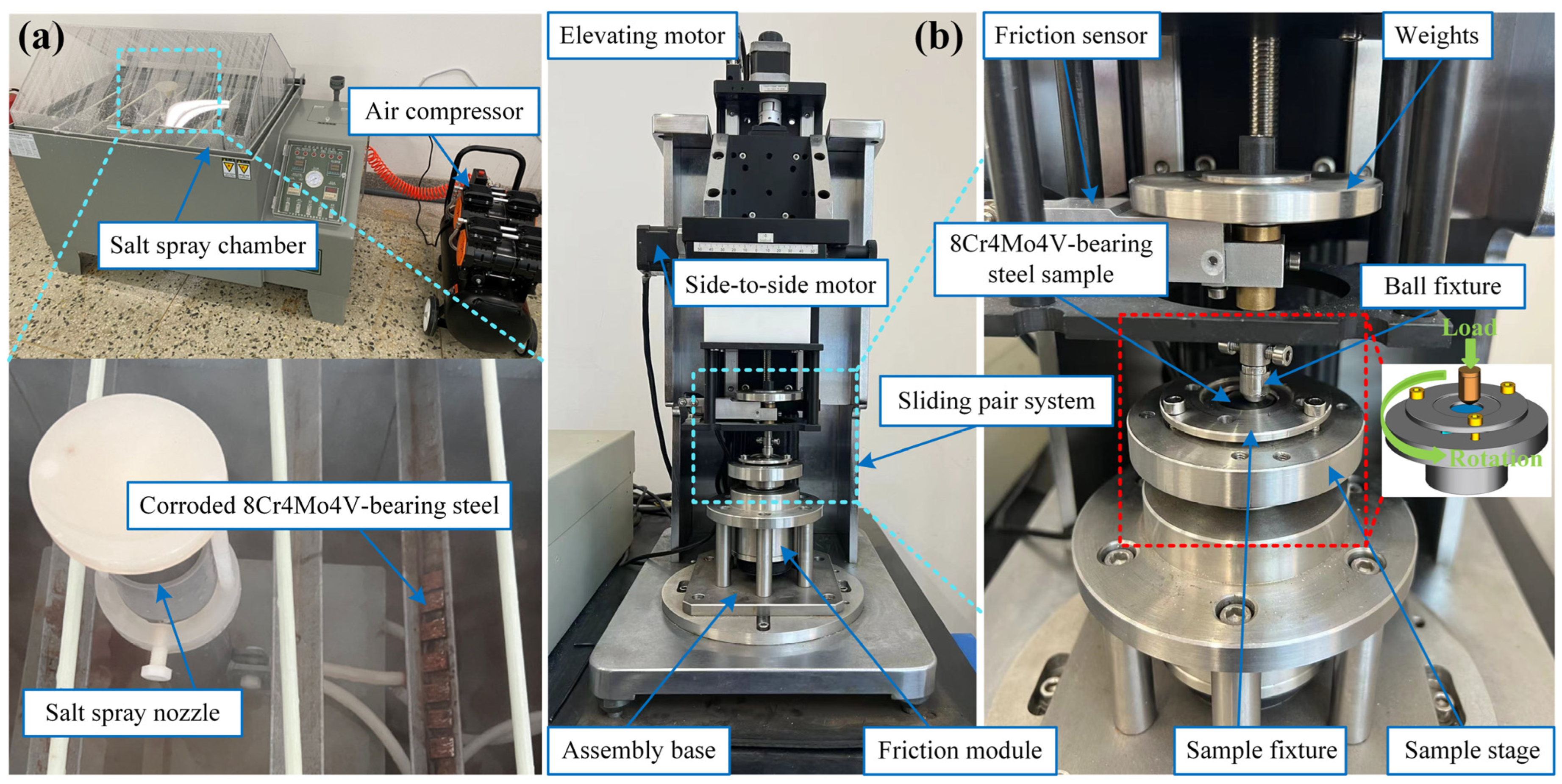
2.2. Neutral Salt Spray Test

Alternating NSS and tribological experiments were used to simulate the CWI behavior of 8Cr4Mo4V bearing steel under a marine atmospheric environment. The CWI behavior of 8Cr4Mo4V bearing steel was studied, including pure corrosion, wear, and corrosion–wear processes.
The NSS test was performed in a salt spray test chamber (OLT, Ningbo, China), where the specimen surfaces were placed horizontally at an angle of 15°–30° with no contact between them, as seen in Figure 1a, and non-corroded areas were encapsulated with silicone rubber. The spray test adopts Bernoulli’s principle to absorb salt water and then atomize it. The degree of atomization is uniform, without blocking the crystallization phenomenon, thus ensuring continuous testing standards. The heating tube is made of a high-temperature, corrosion-resistant titanium tube, adopting direct heating to ensure a fast heating speed. In our test, the corrosion medium was a 5% NaCl solution, with corrosion intervals of 2, 4, 6, 8, 10, 12, 14, 16, 18, and 20 h. The salt spray deposition rate was set at 1~2 mL/h (80 cm2), the air pressure at 0.1 MPa, and the temperature at 35 ± 1 °C. To obtain corroded surface morphologies and the mass loss of the matrix, mechanical descaling and acid cleaning after corrosion were carried out in succession. Then, 500 mL of HCl, 500 mL of deionized water, and 10 g of C6H12N4 were employed to prepare the descaling solution. A constant-temperature magnetic heating stirrer was used to accelerate hexamethylenetetramine dissolution, and then the specimens were immersed in a rust remover for 30 min to strip the corrosive layers. Afterwards, the samples were ultrasonically cleaned with alcohol and distilled water, blow-dried, and placed in a vacuum oven at 50 °C for 1 h. The corrosion weight losses were measured using a high-precision electronic analytical balance with an accuracy of 0.1 mg, and the corroded surface’s macroscopic morphologies were observed. The samples for the alternating corrosion–wear tests only needed to be dried, without any descaling. For each group, three parallel samples were set to ensure experimental data reliability.

2.3. Tribological Experiment

As shown in Figure 1b, the tribological experiments were performed on a ball-on-disc friction and wear tester (SFT-2M, Zhongke Kaihua, Lanzhou, China). A WC steel ball with a diameter of 3 mm was selected as the friction counterpart, kept fixed, and the radius of the wear tracks on the disk was 4 mm. The tribological tests were conducted at a constant rotational speed of 1400 rpm (revolutions per minute) under a normal load of 6 N for 120 min, and the sliding stroke was about 4220.16 m. According to Hertz’s contact theory [35], the contact interface under a normal load, the contact stress conversion calculation, and the corresponding calculation of the maximum spherical contact stress can be expressed as follows:
σ max = 3 F N 2 π a 2
a = 3 F N R 4 E 3
1 E = 1 μ 1 2 E 1 + 1 μ 2 2 E 2
where σmax represents the maximum contact pressure, a is the contact radius, FN indicates the normal load, R represents the counterpart ball radius, E is the equivalent elastic modulus E1 and E2, and μ1 and μ2 correspond to the Young’s modulus and Poisson ratio of the WC steel ball and 8Cr4Mo4V bearing steel, respectively. Thus, WC steel balls were pressed against 8Cr4Mo4V bearing steel under the test conditions, resulting in a maximum contact pressure of 2.508 GPa. The coefficients of friction (COFs) were obtained automatically using a sensor during the sliding process. A dry-sliding tribological test was also conducted for the control group. The specimens were first ultrasonically cleaned for 10 min using an alcohol and acetone solution and then placed in a drying oven for 30 min to remove contaminants and impurities. The arithmetic means of three measurements for the mass losses were taken as the final experimental results. The wear rate values were calculated using Equation (4).
R = M F N L
where R denotes the wear rate, g/N∙m; M is the mass loss, g; FN indicates the normal load, N; and L represents the sliding distance, m.

3. Results and Discussion

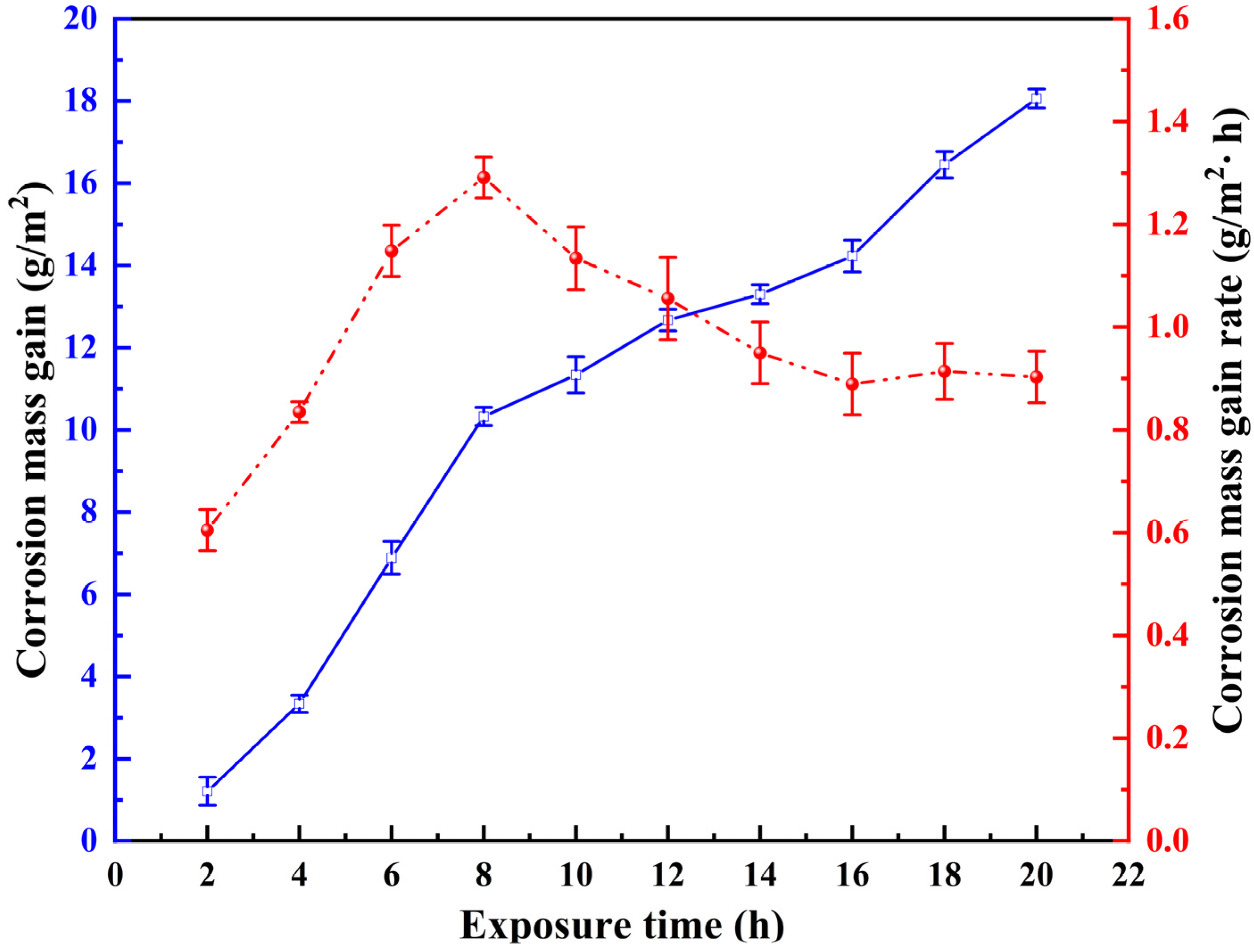
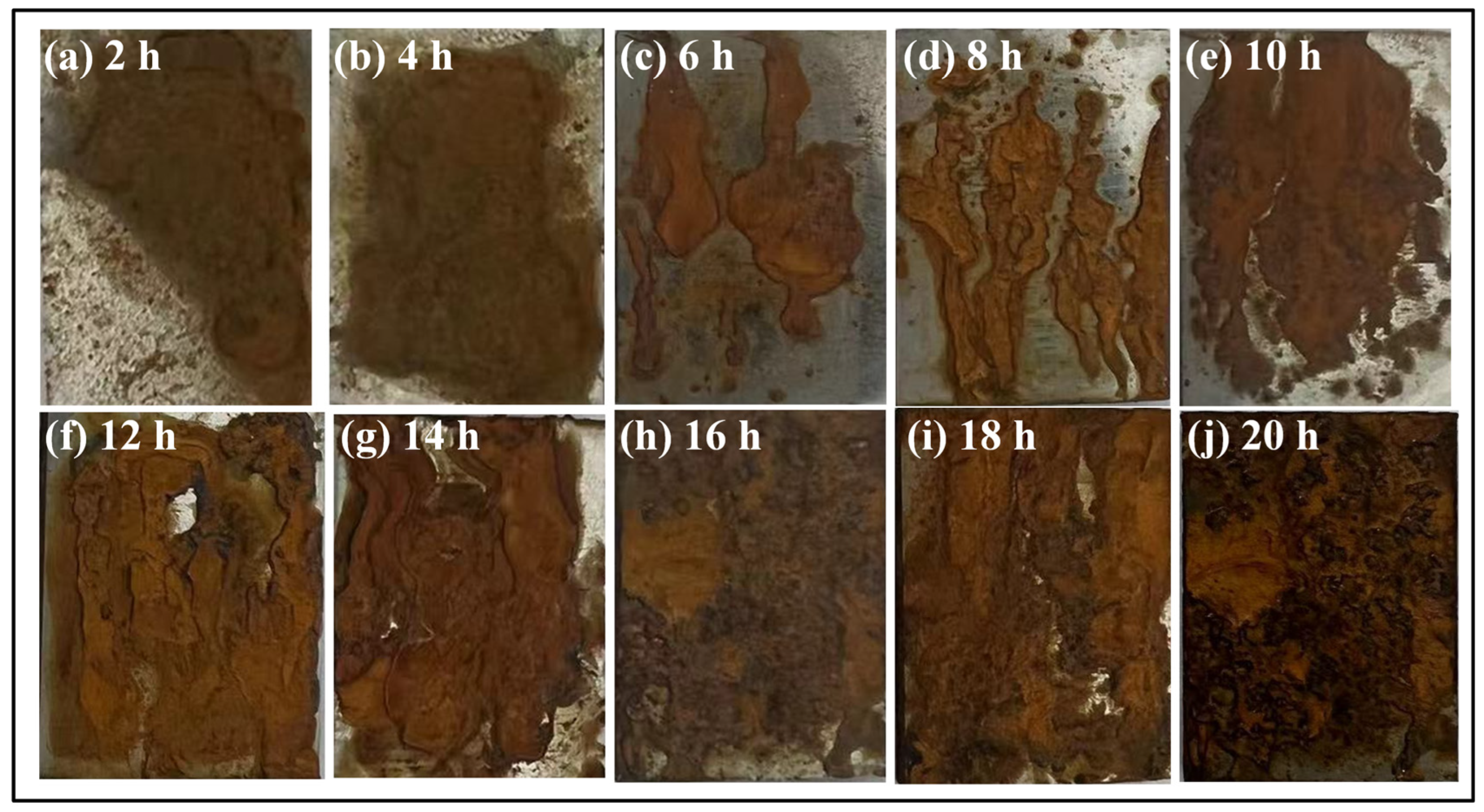
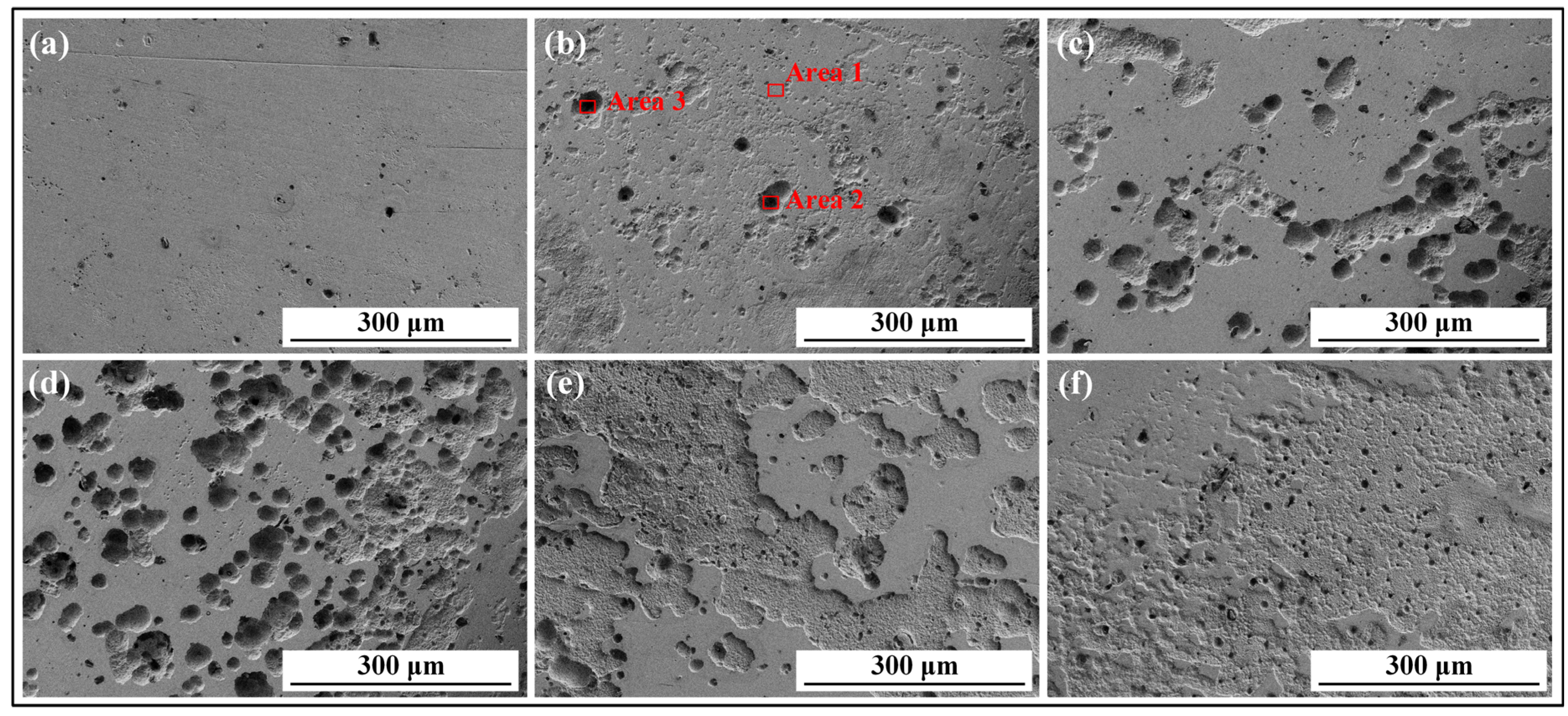
3.1. Influence of Corrosion Interval on 8Cr4Mo4V Bearing Steel Surface Morphologies

To investigate the evolution of the corrosion behavior of 8Cr4Mo4V bearing steel, the curves of the corrosion mass gain rate versus the exposure time in the NSS test were measured, as shown in Figure 2. The corrosion mass gain curves show two stages—rapid weight gain (0~8 h) and steady weight gain (8~20 h)—reaching the maximum after 20 h of corrosion and measuring approximately 18.06 g/m2. By prolonging the salt spray corrosion duration, the corrosion weight gain rate showed a tendency to increase, decrease, and finally, remain stable in the later stage of corrosion (16~20 h). In the early stages of corrosion (0~8 h), the corrosion mass gain rate was minor owing to the oxide layer formed over a short time, protecting the substrate. Due to the direct contact between the surface of 8Cr4Mo4V bearing steel and oxygen, water, and chloride ions, local corrosion was caused by the permeation of chloride ions into the oxide film defects, resulting in a rapid increase in the weight of the specimen and a higher corrosion rate. In the middle stage of corrosion (8~16 h), corrosion weight gain was slower, accompanied by a reduced corrosion rate, due to the protective effect of the surface oxide layer on the alloy matrix. In the later stages of corrosion (16~20 h), as the corrosion products became denser, their layered film evolved into a rust layer with a physical barrier, reducing the corrosion mass gain rate by blocking the downward seepage channels to the substrate of chloride ions. In their work, Su et al. also found that the corrosion rate first decreased and then increased with the duration, possibly due to changes in the rust layer composed of α-FeOOH, γ-FeOOH, and Fe3O4 generated on the surface of U68CuCr rail steel samples [28].
To describe the evolution of 8Cr4Mo4V bearing steel’s corrosion behavior under different corrosion cycles in the NSS test, macrographs of rust morphologies were observed, as shown in Figure 3. The figure depicts corroded macro-morphologies covering the entire rusty surface of the specimen. At the initial stage of corrosion, the corrosion products on the surface were small and scattered (see Figure 3a,b), while the samples that had been corroded for 6 h showed a local rust layer (see Figure 3c). With the increase in the length of the corrosion cycles, the surface appearance of the rust layer gradually changed from a bright color to a darker color, especially around the edges—namely from orange to brown, then dark brown, and finally, yellowish brown. With the increase in the corrosion intervals, the surface rust layers became closer and the area covered larger, indicating that the corrosion rate of 8Cr4Mo4V bearing steel gradually increased with time (see Figure 3e,f). The exposed surface of the sample was almost completely covered in rust from 16 h onwards, while localized softness, bulging, and peeling noticeably reduced and its flatness improved. This suggested that 8Cr4Mo4V bearing steel corrosion shifted from local, severe erosion to overall uniform and comprehensive corrosion (see Figure 3h). It is worth noting that the stage of localized corrosion mainly took place between 6 and 14 h, divided into formation (6~10 h) and diffusion phases (10~14 h). In the former, the rust layer originating from the center grew perpendicularly in the horizontal direction, and then spread from the center in all directions during the diffusion stage. Compared to local severe erosion (6~14 h), the rust layer presented more noticeable stratification (see Figure 3j) during uniform corrosion (16~20 h). Two rust layers formed on the 8Cr4Mo4V bearing steel surface. The inner layer, adjacent to the steel substrate, was darker in color, indicating denser corrosion products, and presented improved substrate bonding.
To explain the formation, growth, and evolution processes of corrosion products and layers, both low- and high-magnification SEM micrographs of the marked corrosion morphologies under different durations (2, 6, 12, 18, and 20 h) of the NSS test are shown in Figure 4. The sub-stable corrosion product β-FeOOH exhibited a monolayer, powdery, and needle-leaf distribution after 2 h of corrosion, as shown in Figure 4a. However, after 6 h, the corrosion products increased in number and size, presenting a multilayer structure in the high-magnification image, while relatively minor corrosion rates resulted in insufficiently dense corrosion products (see Figure 4b). With the increase in the localized corrosion degrees, a large number of spherical clusters were formed on the substrate surface (see Figure 4c). The connection of these corrosion products resulted in the formation of a rust layer, indicating the conversion from local to total corrosion, consistent with the macroscopic surface morphology of the substrate after 12 h. However, the corrosion products’ structure was still relatively loose and presented more holes, as shown in the high-magnification SEM micrographs. As corrosion continued, the corrosion products generated after 20 h were stacked on top of each other, increasing the thickness of the multilayered rust coating (see Figure 3f) and the number of holes inside it, leading to a loose structure and triggering shedding and flow rust phenomena. This can be attributed to a large number of sub-stable steel corrosion products, such as β-FeOOH, with a tetragonal, loosely tunneled crystal structure, which could be used to carry Cl [36], and a lower density compared to α-FeOOH. The β-FeOOH rust layer had more internal holes and crack defects, making it prone to blistering, peeling, and cracking, and the formation of a stabilized rust layer protecting the substrate was difficult. In the later stages of corrosion (18~20 h), granular and agglomerated corrosion products began to transform into laminar and cotton-ball corrosion products with larger sizes. The rust layer formed at this stage was relatively dense, owing to stable α-FeOOH [37]. Microcracks were also found after 18 h, as shown in the high-magnification SEM micrographs in Figure 4e.
The rust removal effect was employed to evaluate the bonding strength between the rust layer and the substrate. The rust sublayer morphologies were obtained at half of the removal time (15 min), as shown in Figure 5. During the descaling process, a noticeable delamination region (yellow-colored areas) occurred with the increase in corrosion cycle durations. The removal of the rust layer from the substrate’s surface was worse, possibly due to the better stability and greater bonding strength. In this case, the substrate’s surface was locally corroded during the early stage of corrosion (see Figure 5a,b), while the remaining, larger area developed during the middle and late phases (12~20 h), indicating an increase in the corrosion rate and the transformation of localized corrosion into a full-scale corrosion behavior, as confirmed in Figure 3. Additionally, pitting (yellow frame) could be observed on the surface after rust removal due to the looser rust layer formed in the early stage of corrosion, while micro-furrowed morphologies with larger delamination regions were present after rust removal during the later phases, as shown in Figure 5e,f. Here, the corrosion pits were covered by a uniformly dense, stable rust layer that was difficult to observe, in agreement with Figure 4f.
To further expose the surface damage and destruction of the 8Cr4Mo4V bearing steel substrate under the NSS test, the surface topographies and pits after the removal of the rust layer were obtained, as shown in Figure 6. After 2 h of salt spray corrosion, some small, mutually discontinuous pits around 6 μm in diameter appeared on the substrate’s surface (see Figure 6a). After 6 h, the amount of small, shallow pits increased significantly, connecting with one another to form corrosion spots, and a few of them reached diameters of 15 μm. EDS point-selected area scanning was used to analyze the pits’ elemental distribution (see Figure 6b), listed in Table 2. The matrix had a low chloride ion content, while many of these ions accumulated in the pits, increasing as the latter grew in size. Therefore, when the oxide film or rust layer was corroded by the NaCl medium, micro-pits were formed, corroding deeper into the substrate. Due to the buildup and flow of the NaCl liquid under the matrix, the corrosion pits interconnected and expanded, forming spots and gullies. After 12 h, the pits essentially developed into large (18 μm) interconnected holes, covering a significantly larger area. After 16 h, their density, diameter (20 μm), and depth increased significantly, with local corrosion showing a gull-like shape and a tendency toward uniform corrosion (see Figure 6d). In addition, nested pits were observed at the bottom of localized corrosion spots, indicating their continued growth. As time went on, large pits significantly reduced in number, over 50% of the substrate’s surface became covered in corrosion spots, and the mode of corrosion was a combination of localized and uniform (see Figure 6e). After 20 h, the corrosion spots further expanded and connected, the surface was almost completely corroded, with pits still visible at the bottom, and total corrosion was the dominating behavior (see Figure 6f). In summary, the 8Cr4Mo4V bearing steel surface first produced sporadic localized corrosion, which gradually expanded and interconnected to form corrosion spots. Then, these spots developed over time into wider, uniform corrosion. Meanwhile, new localized corrosion was induced by chloride ions at the bottom of the corrosion spots, generating a pattern dominated by total corrosion, with nested localized corrosion also present.

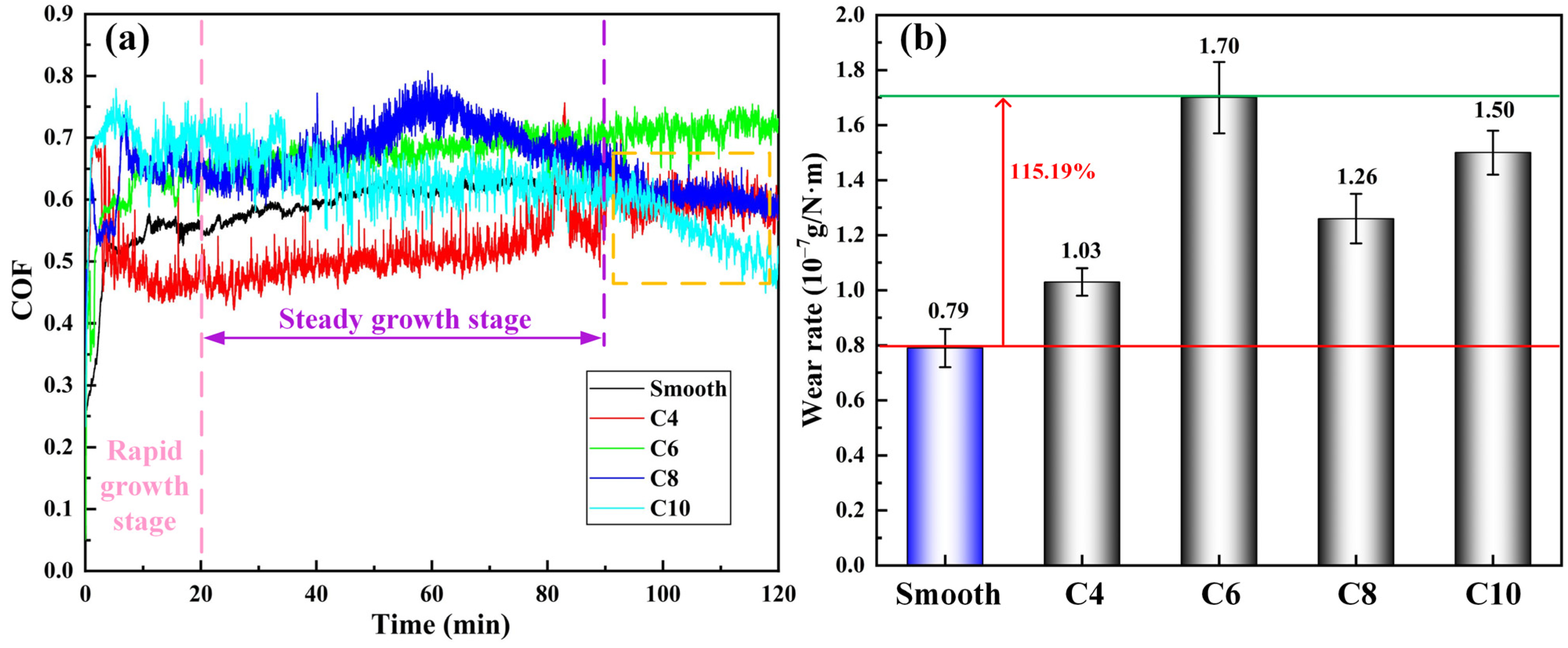
3.2. Influence of Corrosion on 8Cr4Mo4V Bearing Steel Tribological Performance

Considering the mutual coupling of corrosion and wear and their spatio-temporal interaction mechanisms, corrosion–wear interaction behaviors have mainly been studied in terms of the effect of corrosion on wear, the impact of wear on corrosion, and the quantification of corrosion–wear interactions. 8Cr4Mo4V bearing steel’s corrosion–wear interaction can be better investigated by quantifying various material loss components during corrosion and wear processes, and the relationship between them is pictured in Figure 7. The total material losses in the corrosion–wear process are indicated by T2, while T1 represents the material losses in the process, W1 those under pure wear, and C1 and C2 those of pure corrosion during the first and second phase, respectively. The wear component (WC) is formed by W1 and the wear increment (∆WC) induced by the corrosive effect; meanwhile, the corrosion component (CW) comprises C2 and the corrosion increment (∆CW) induced by the abrasion effect. The material loss caused by the interaction of corrosion and wear is defined as Y, consisting of ∆WC and ∆CW. To further investigate the corrosion–wear interaction mechanism, the ratio of CWI (N = Y/T2), the corrosion contribution (Q = ∆WC/Y), and the wear contribution (P = ∆CW/Y) were separately defined.
To investigate corrosion’s effect on friction in CWI behaviors, the 8Cr4Mo4V bearing steel’s COF curves and wear rates in the corrosion–wear process were obtained, as shown in Figure 8a. When the friction pair components slid relative to one another, the surface micro-convexities were more prone to direct contact and collision, and larger COF fluctuations occurred in the corroded specimens compared to the uncorroded samples due to the corrosion craters and products, exacerbating the abrasive wear between the surfaces [38]. All COF curves showed running-in and stabilization stages before 90 min of wear, with C4 having the lowest average COF (0.5) compared to the matrix (0.6) due to the friction reduction caused by its uniform rust layer, which was exhausted after this time elapsed, leading to increased COFs. However, C8 and C10 showed reduced COFs below 0.6 after 90 min, with the extrusion of the loose corrosion layer. Due to the localized corrosion layer’s dispersion and incompleteness (see Figure 3), corrosion products found it difficult to cover the pits and the absence of the contact surface’s anti-friction layer resulted in larger contact stress and a stress concentration phenomenon; as such, C6’s COF continually increased throughout the wear process. Additionally, all corroded samples had large COF curve fluctuations, while almost none were recorded in the uncorroded model. The average COFs (20–120 min) of the uncorroded matrix, C4, C6, C8, and C10 were 0.6042, 0.5367, 0.6873, 0.6628, and 0.6140, respectively, with C6 being the largest.
All corroded samples had larger wear rates than the smooth samples (see Figure 8b), demonstrating that corrosion promoted material losses in 8Cr4Mo4V bearing steel’s wear behavior. This can be attributed to the surface damage features and rougher surface topographies caused by corrosion. C6 presented the highest wear rate, which was 2.15 times that of the uncorroded samples, indicating the largest acceleration of corrosion on wear. This was due to the poor bonding force of C6’s rust sublayer, resulting in corrosion products being able to more easily leave the surface by friction and vibration (see Figure 5b). Meanwhile, the surface rust layer was neither homogeneous nor abundant (see Figure 3c), and the pits’ uneven distribution made it difficult to store debris, generate an anti-wear layer, and decrease contact stress, as shown in Figure 6b. The corroded samples’ worn surface morphologies, shown in Figure 9, include a number of damage features (grooves, depressions, and scratches), with a damage pattern comprising abrasive wear, delamination, spalling, and crushing [39]. The yellow and red areas represent raceway wear tracks and crushed corrosion pits after the friction and wear tests, respectively. The crushing phenomenon that is clearly visible in the figure took place in the corrosion pits in C6’s wear mark, contributing to its larger wear loss. One of the corroded samples with shorter exposure times (C4) presented the lowest wear rate due to having fewer pits on the corroded surface during the sliding process. As the corrosion time increased, the surface rust layer gradually became denser and more uniform (see Figure 4), more easily covering the micro-holes and interconnected corrosion areas, as shown in Figure 9c,d. Owing to the enhanced bonding force of the rust sublayer, the damage’s shape transformation, and a certain protective effect of the rust layer, the wear rates of C8 and C10 were both lower than that of C6. C10 had a larger wear rate compared to C8, attributed to a more severe corrosion degree, which resulted in a greater crushed pit zone on the worn surface. In their study, Su et al. [28] also found that the degree of damage after wear tests was more serious in corroded steel compared to non-corroded samples due to the interaction between corrosion and wear behaviors over various lengths of time, with the only difference being the wear rates increasing during longer corrosion cycles. Consequently, the relationship between corrosion’s acceleration effect on wear and its duration is not a completely positive correlation under specific conditions, influenced by the coupling effect of the distribution of the rust layers (morphology, quantity, and bonding force) and corrosion pits (number, size, and morphology).

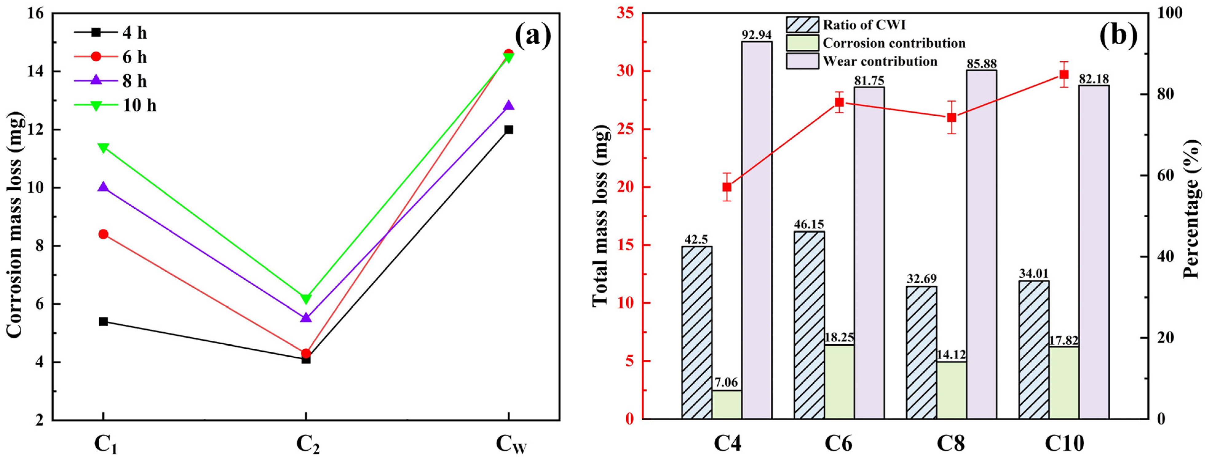
3.3. Quantitative Characterization of 8Cr4Mo4V Bearing Steel Corrosion–Wear Interaction

To investigate the impact of wear on corrosion in CWI behaviors, we obtained the pure corrosion mass loss during the first (C1) and second cycles (C2) and the corrosion component (CW), as shown in Figure 10a. Under pure corrosion conditions, the material loss of the first and second cycles increased with longer corrosion times. When the corrosion interval was fixed, the material loss in the second cycle stage was lower compared to the first cycle. However, the material losses at all corrosion intervals in the second stage, under corrosion–abrasion conditions, were much greater than those under corrosion alone, indicating that wear accelerated the material losses in 8Cr4Mo4V bearing steel corrosion. When the corrosion intervals were 6 h and 10 h, the latter generated the largest material loss, but the corrosion mass loss rate was highest after 6 h, which implies that the wear–corrosion behavior was the most serious at this time and the acceleration effect of wear on corrosion was the most significant. Consequently, the relationship between the acceleration effect of wear on corrosion and the duration of the latter was not a completely positive correlation under specific conditions.
In summary, combined with the above experimental results on corrosion and wear behaviors, the interaction between the corrosion and wear of 8Cr4Mo4V bearing steel under specific test conditions showed a synergistic acceleration effect. The following CWI mechanisms of 8Cr4Mo4V bearing steel were derived: (1) Due to corrosion, the surface integrity of 8Cr4Mo4V bearing steel was compromised and deteriorated, with cracks, pits, and corrosion products on the surface topographies. After the interaction between corrosion and wear, the increase in contact stress led to greater interfacial friction, and the development of larger wear pits and plastic deformation layers resulted in more serious wear. Thus, corrosion aggravated the degree of wear. (2) After the tribological test, the worn sample surface became rougher overall. Owing to the convenient sites provided by the wear pits and delamination, salt spray solution deposition was promoted throughout the corrosion process. In addition, the substrate’s surface and subsurface were prone to corrosive medium permeation along the contact cracks and wear marks. As such, the wear further accelerated the corrosion degree.
As shown in Figure 10b, the total mass loss, CWI ratio, and corrosion and wear contributions for 8Cr4Mo4V bearing steel under different corrosion–abrasion intervals were analyzed to quantify the corrosion–wear interactions. With the increase in corrosion intervals, the overall mass losses essentially appeared to have an increasing trend. As C8 had a lower corrosion–wear interaction ratio compared to C6 and C10, and its corrosion–wear synergistic accelerating effect was weak, leading to decreased total mass losses. The corrosion–wear interaction ratios of C8 and C10 were lower than those of C4 and C6, due to the greater material loss caused by longer pure corrosion behaviors. The corrosion–wear interaction degree was higher in the early stages of corrosion (4 h and 6 h), with the highest corrosion–wear interaction ratio of about 46.15% observed after 6 h, which was 13.46% higher than that measured after 8 h. Since C4’s corrosion rate was higher and its worn surface more prone to induced material corrosion, the highest wear contribution was obtained after 4 h, measuring about 92.94%. It is also noteworthy that the highest corrosion contribution was about 18.25%, after 6 h.

4. Conclusions

The corrosion–wear interaction (CWI) behavior of 8Cr4Mo4V bearing steel after different corrosion intervals was explored by NSS tests combined with tribological experiments. The component relationships in the corrosion–wear process were established, and the quantitative characterization of CWI behavior was analyzed. The following conclusions can be drawn.
Corrosion accelerates wear, and the latter facilitates the former. The interaction between the corrosion and wear of 8Cr4Mo4V bearing steel under specific test conditions showed a synergistic acceleration effect. Corrosion changed the COF curve trends, and the COF values of most corroded samples in the third stage presented a decreasing pattern compared to the uncorroded samples due to friction-reducing uniform rust layers.
The total mass loss of the samples was primarily caused by corrosion behaviors. The sample corroded for 6 h had the largest corrosion–wear interaction ratio, approximately 46.15%, indicating the most significant effect. This sample’s corrosion contribution was also the highest (18.25%), indicating the evident facilitating impact of corrosion on wear.
The influence of the corrosion environment (e.g., temperature, salinity, and corrosive medium) and wear conditions (e.g., load, speed, and counter-grinding material) on the corrosion–wear interaction behaviors of 8Cr4Mo4V bearing steel is a promising direction for future research.

Author Contributions

Conceptualization, L.Y. and C.Z.; methodology, C.Z.; software, C.Z.; validation, C.N., T.Z. and R.T.; formal analysis, C.Z.; investigation, C.Z.; resources, L.Y.; data curation, R.L.; writing—original draft preparation, C.Z.; writing—review and editing, C.Z.; visualization, C.Z.; supervision, C.Z.; project administration, L.Y.; funding acquisition, L.Y. All authors have read and agreed to the published version of the manuscript.

Funding

The research was supported by the National Natural Science Foundation of China (No. 52075112), the National Key R & D Program of China for Young Scientists (No. 2021YFB2011200).

Institutional Review Board Statement

This study did not involve experiments using human tissue.

Informed Consent Statement

Not applicable.

Data Availability Statement

The original codes and data used to support the findings of this study are available from the corresponding author upon request.

Conflicts of Interest

The author(s) declare no potential conflicts of interest with respect to the research, authorship, and/or publication of this article.

Abbreviations

AbbreviationsItems
CWICorrosion–wear interaction
RCFRolling contact fatigue resistance
HCPEBHigh energy current pulsed electron beam
NABNickel aluminum bronze
NSSNeutral salt spray
SEMScanning electron microscope
EDSEnergy-dispersive spectroscopy
rpmRevolutions per minute
COFCoefficient of friction
T2Total material losses in corrosion–wear–corrosion process
T1Material losses in corrosion–wear process
W1Material losses of pure wear
C1Material losses of pure corrosion for the first phase
C2Material losses of pure corrosion for the second phase
WCWear component
WCWear increment
CWCorrosion component
CWCorrosion increment
YMaterial loss caused by the interaction of corrosion and wear
NRatio of CWI
QCorrosion contribution
PWear contribution

References

  1. Jiang, H.W.; Song, Y.R.; Wu, Y.C.; Shan, D.B.; Zong, Y.Y. Macrostructure, microstructure and mechanical properties evolution during 8Cr4Mo4V steel roller bearing inner ring forging process. Mat. Sci. Eng. A 2020, 798, 140196. [Google Scholar] [CrossRef]
  2. Elsheikh, A.H.; Yu, J.G.; Sathyamurthy, R.; Tawfik, M.M.; Shanmugan, S.; Essa, F.A. Improving the tribological properties of AISI M50 steel using Sns/Zno solid lubricants. J. Alloys Compd. 2020, 821, 153494. [Google Scholar] [CrossRef]
  3. Zhang, B.H.; Liu, H.T.; Zhang, M.L.; Dai, C.Y.; Xie, Z.W.; Ma, X.X.; Sun, Y.Z. New layering strategy and the gradient microstructure distribution of surface metamorphic layer for 8Cr4Mo4V steel by grinding. Arch. Civ. Mech. Eng. 2024, 24, 42. [Google Scholar] [CrossRef]
  4. Bhadeshia, H.K.D.H. Steels for bearings. Prog. Mater. Sci. 2012, 57, 268–435. [Google Scholar] [CrossRef]
  5. Zhao, C.; Long, R.S.; Zhang, Y.M.; Wang, Y.B.; Wang, Y.Y. Influence of characteristic parameters on the tribological properties of vein-bionic textured cylindrical roller thrust bearings. Tribol. Int. 2022, 175, 107861. [Google Scholar] [CrossRef]
  6. Litwin, W.; Dymarski, C. Experimental research on water-lubricated marine stern tube bearings in conditions of improper lubrication and cooling causing rapid bush wear. Tribol. Int. 2016, 99, 449–455. [Google Scholar] [CrossRef]
  7. Liu, Y.W.; Zhao, H.T.; Wang, Z.Y. Initial corrosion behavior of carbon steel and weathering steel in nansha marine atmosphere. Acta Metall. Sin. 2020, 56, 1247–1254. [Google Scholar]
  8. Dong, B.J.; Liu, W.; Zhang, T.Y.; Chen, L.J.; Fan, Y.M.; Zhao, Y.G.; Yang, W.J.; Banthukul, W. Corrosion failure analysis of low alloy steel and carbon steel rebar in tropical marine atmospheric environment: Outdoor exposure and indoor test. Eng. Fail. Anal. 2021, 129, 105720. [Google Scholar] [CrossRef]
  9. Liu, Y.; Ma, S.G.; Gao, M.C.; Zhang, C.; Zhang, T.; Yang, H.J.; Wang, Z.H.; Qiao, J.W. Tribological properties of AlCrCuFeNi2 high-entropy alloy in different conditions. Metall. Mater. Trans A 2016, 47A, 3312–3321. [Google Scholar] [CrossRef]
  10. Wood, R.J.K. Marine wear and tribocorrosion. Wear 2017, 376, 893–910. [Google Scholar] [CrossRef]
  11. Wang, Y.; Xu, W.C.; Wang, X.T.; Jiang, Q.T.; Li, Y.T.; Huang, Y.L.; Yang, L.H. Research on dynamic marine atmospheric corrosion behavior of AZ31 magnesium alloy. Metals 2022, 12, 1886. [Google Scholar] [CrossRef]
  12. Li, N.; Zhang, W.F.; Xu, H.; Cai, Y.K.; Yan, X.J. Corrosion behavior and mechanical properties of 30CrMnSiA high-strength steel under an indoor accelerated harsh marine atmospheric environment. Materials 2022, 15, 629. [Google Scholar] [CrossRef]
  13. Lu, Y.F.; Dong, J.H.; Ke, W. Effects of Cl- ions on the corrosion behaviour of low alloy steel in deaerated bicarbonate solutions. J. Mater. Sci. Technol. 2016, 32, 341–348. [Google Scholar] [CrossRef]
  14. Mukhopadhyay, P.; Srinivas, M.; Roy, M. Microstructural developments during erosion of tribological steels. Mater. Charact. 2016, 113, 43–51. [Google Scholar] [CrossRef]
  15. Xu, F.J.; Guo, G.W.; Tang, G.Z.; Ma, X.M.; Wang, L.Q.; Ozur, G.E.; Yukimura, K. Microstructure modifications and corrosion behaviors of Cr4Mo4V steel treated by high current pulsed electron beam. Mater. Chem. Phys. 2011, 126, 904–908. [Google Scholar] [CrossRef]
  16. Essa, F.A.; Elsheikh, A.H.; Yu, J.G.; Elkady, O.A.; Saleh, B. Studies on the effect of applied load, sliding speed and temperature on the wear behavior of M50 steel reinforced with Al2O3 and/or graphene nanoparticles. J. Mater. Res. Technol. 2021, 12, 283–303. [Google Scholar] [CrossRef]
  17. Zhang, C.W.; Peng, B.; Wang, L.Q.; Ma, X.X.; Gu, L. Thermal-induced surface damage of M50 steel at rolling-sliding contacts. Wear 2019, 420, 116–122. [Google Scholar] [CrossRef]
  18. Bhattacharyya, A.; Subhash, G.; Arakere, N.; Allison, B.D.; Mccoy, B. Influence of residual stress and temperature on the cyclic hardening response of M50 high-strength bearing steel subjected to rolling contact fatigue. J. Eng. Mater. Technol. 2016, 138, 021003. [Google Scholar] [CrossRef]
  19. Zhang, C.; Gu, L.; Tang, G.Z.; Mao, Y.Z. Wear transition of CrN coated M50 steel under high temperature and heavy load. Coatings 2017, 7, 202. [Google Scholar] [CrossRef]
  20. Wang, F.; Qian, D.S.; Hua, L.; Lu, X.H. The effect of prior cold rolling on the carbide dissolution, precipitation and dry wear behaviors of M50 bearing steel. Tribol. Int. 2019, 132, 253–264. [Google Scholar] [CrossRef]
  21. Huang, Q.P.; Shi, X.L.; Ma, J. Tribological behavior of surface bionic rhombic-textured M50 steel containing SnAgCu and MXene-Nb2C under dry sliding conditions. J. Mater. Eng. Perform. 2021, 30, 9390–9402. [Google Scholar] [CrossRef]
  22. Essa, F.A.; Zhang, Q.X.; Huang, X.J. Investigation of the effects of mixtures of WS2 and ZnO solid lubricants on the sliding friction and wear of M50 steel against silicon nitride at elevated temperatures. Wear 2017, 374, 128–141. [Google Scholar] [CrossRef]
  23. Yan, Y.; Neville, A.; Dowson, D.; Williams, S. Tribocorrosion in implants—Assessing high carbon and low carbon Co-Cr-Mo alloys by in situ electrochemical measurements. Tribol. Int. 2006, 39, 1509–1517. [Google Scholar] [CrossRef]
  24. Rajahram, S.S.; Harvey, T.J.; Wood, R.J.K. Erosion-corrosion resistance of engineering materials in various test conditions. Wear 2009, 267, 244–254. [Google Scholar] [CrossRef]
  25. Jiang, J.; Stack, M.M.; Neville, A. Modelling the tribo-corrosion interaction in aqueous sliding conditions. Tribol. Int. 2002, 35, 669–679. [Google Scholar] [CrossRef]
  26. Zhang, B.B.; Wang, J.Z.; Yuan, J.Y.; Yan, F.Y. Tribocorrosion behavior of nickel aluminum bronze in seawater: Identification of corrosion-wear components and effect of pH. Mater. Corros. 2018, 69, 106–114. [Google Scholar] [CrossRef]
  27. Zhang, Q.; Zhu, M.; Cai, F.; Liu, M.; Su, X.; Xu, G. Corrosion performance of a corrosion-resistant rail steel in the simulated subsea tunnel environment. Corros. Rev. 2021, 39, 561–571. [Google Scholar] [CrossRef]
  28. Su, X.; Xu, G.; Zhu, M.; Zhang, Q.; Cai, F.; Liu, M. Investigation on the interaction between corrosion and wear of U68CuCr rail steel with different corrosion periods. Wear 2023, 516, 204598. [Google Scholar] [CrossRef]
  29. Hou, X.B.; Wang, Y.X.; Dai, L.Y.; Yang, Y.H.; Du, J.H.; Wang, Y.J.; Wan, H. Study on the corrosion and wear behaviors of cylinder liner in marine diesel engine burning low sulfur fuel oil. Eng. Fail. Anal. 2023, 147, 107151. [Google Scholar] [CrossRef]
  30. Wang, W.L.; Cui, W.F.; Xiao, Z.T.; Qin, G.W. The improved corrosion and wear properties of Ti-Zr based alloys with oxide coating in simulated seawater environment. Surf. Coat. Technol. 2022, 439, 128415. [Google Scholar] [CrossRef]
  31. Xu, Z.B.; Huang, Z.Y.; Wang, Y.C.; Lin, C.X.; Xu, X. Friction and wear behavior of C17200 copper-beryllium alloy in dry and wet environments. J. Mater. Eng. Perf. 2021, 30, 7545–7551. [Google Scholar] [CrossRef]
  32. Ding, H.R.; Zhou, G.H.; Dai, Z.D.; Bu, Y.F.; Jiang, T.Y. Corrosion wear behaviors of 2024Al in artificial rainwater and seawater at fretting contact. Wear 2009, 267, 292–298. [Google Scholar] [CrossRef]
  33. Jun, C. Corrosion wear characteristics of TC4, 316 stainless steel, and Monel K500 in artificial seawater. Rsc Adv. 2019, 7, 23835–23845. [Google Scholar] [CrossRef]
  34. Simsek, D. An investigate on hot wear and corrosion performance of Al matrix hybrid composites produced by mechanical alloying method. Arab. J. Sci. Eng. 2022, 47, 15477–15487. [Google Scholar] [CrossRef]
  35. Li, Z.C.; Wang, Y.X.; Cheng, X.Y.; Zeng, Z.X.; Li, J.L.; Lu, X.; Wang, L.P.; Xue, Q.J. Continuously growing ultrathick CrN coating to achieve high load-bearing capacity and good tribological property. ACS Appl. Mater. Interfaces 2018, 10, 2965–2975. [Google Scholar] [CrossRef]
  36. Zhang, X.; Gong, L.; Feng, Y.P.; Wang, Z.H.; Yang, M.; Cheng, L.; Liu, J.; Wu, K.M. Effect of retained austenite on corrosion behavior of ultrafine bainitic steel in marine environment. Acta Metall. Sin. (Engl. Lett.) 2023, 36, 717–731. [Google Scholar] [CrossRef]
  37. Sun, M.H.; Yang, X.J.; Du, C.W.; Liu, Z.Y.; Li, Y.; Wu, Y.M.; San, H.Y.; Su, X.D.; Li, X.G. Distinct beneficial effect of Sn on the corrosion resistance of Cr–Mo low alloy steel. J. Mater. Sci. Technol. 2021, 81, 175–189. [Google Scholar] [CrossRef]
  38. Wu, F.H.; Zhang, N.; Sun, Y.B.; Li, X.; Liu, Z.J.; Yang, Y.L. Effect of applied load on tribological behaviour of Ti-48Al-2Cr-2Nb alloy under oil-lubricated condition. Wear 2024, 538, 205210. [Google Scholar] [CrossRef]
  39. Komotori, J.; Hisamori, N.; Ohmori, Y. The corrosion/wear mechanisms of Ti-6Al-4V alloy for different scratching rates. Wear 2007, 263, 412–418. [Google Scholar] [CrossRef]
Figure 1. Schematic image of the salt spray chamber (a). Clamping image of the SFT-2M friction and wear testing machine and schematic diagram of its ball-on-disc tribo-pair (b).
Coatings 14 01245 g001
Figure 2. Corrosion kinetics analysis for 8Cr4Mo4V bearing steel.
Coatings 14 01245 g002
Figure 3. Rust layer macro-morphologies of 8Cr4Mo4V bearing steel after different corrosion intervals. (a) 2 h; (b) 4 h; (c) 6 h; (d) 8 h; (e) 10 h; (f) 12 h; (g) 14 h; (h) 16 h; (i) 18 h; (j) 20 h.
Coatings 14 01245 g003
Figure 4. Low-magnification SEM micrographs of 8Cr4Mo4V bearing steel corrosion morphologies with different durations—(a) 2, (b) 6, (c) 12, (d) 16, (e) 18, and (f) 20 h—and high-magnification SEM micrographs of the marked area.
Coatings 14 01245 g004
Figure 5. SEM micrographs of 8Cr4Mo4V bearing steel rust sublayer morphologies after different corrosion intervals: (a) 2, (b) 6, (c) 12, (d) 16, (e) 18, and (f) 20 h.
Coatings 14 01245 g005
Figure 6. SEM micrographs of corroded 8Cr4Mo4V bearing steel morphologies after different corrosion intervals: (a) 2, (b) 6, (c) 12, (d) 16, (e) 18, and (f) 20 h.
Coatings 14 01245 g006
Figure 7. Schematic component relationship diagram for 8Cr4Mo4V bearing steel material losses in the corrosion–wear process.
Coatings 14 01245 g007
Figure 8. COF curves (a) and wear rates (b) of 8Cr4Mo4V bearing steel in the corrosion–wear interaction process.
Coatings 14 01245 g008
Figure 9. Worn surface morphologies of corroded 8Cr4Mo4V bearing steel after different corrosion intervals.
Coatings 14 01245 g009
Figure 10. Corrosion mass losses of 8Cr4Mo4V bearing steel with and without wear (a) and the quantitative characterization of component relationships (b) in corrosion–wear processes.
Coatings 14 01245 g010
Table 1. Chemical composition of 8Cr4Mo4V bearing steel (wt.%).
SteelCCrMoVSiMnSFe
8Cr4Mo4V0.75~0.853.75~4.254.00~4.500.90~1.10≤0.25≤0.35≤0.20Balance
Table 2. EDS results for corroded 8Cr4Mo4V bearing steel (wt.%).
GroupsCOFeMoClVCr
Area 15.652.1532.9434.850.4012.6011.41
Area 213.7910.9247.8612.712.280.1012.31
Area 319.905.5139.134.085.1911.7814.41
Disclaimer/Publisher’s Note: The statements, opinions and data contained in all publications are solely those of the individual author(s) and contributor(s) and not of MDPI and/or the editor(s). MDPI and/or the editor(s) disclaim responsibility for any injury to people or property resulting from any ideas, methods, instructions or products referred to in the content.

