Article

Preparation and Performance of a Cr/CrN/TiAlCN Composite Coating on a GCr15 Bearing Steel Surface

1
School of Mechanical Engineering and Automation, Wuhan Textile University, Wuhan 430200, China
2
Hubei Engineering Research Center for Intelligent Assembly of Industrial Detonators, Wuhan 430200, China
*
Author to whom correspondence should be addressed.
Coatings 2024, 14(7), 782; https://doi.org/10.3390/coatings14070782
Submission received: 22 May 2024 / Revised: 14 June 2024 / Accepted: 18 June 2024 / Published: 21 June 2024
(This article belongs to the Topic Advances in Functional Thin Films)

Abstract

:
In order to enhance the surface properties of GCr15 bearing steel, a TiAlCN coating with a low friction coefficient, high hardness, and excellent adhesion was fabricated. The TiAlCN multilayer coating was deposited onto the GCr15 bearing steel surface using magnetron sputtering technology, and optimal coating parameters were achieved by adjusting the number of layers, sputtering power of the graphite target, and coating duration. The experimental results showed that adding Cr/CrN as a transition layer between GCr15 bearing steel and TiAlCN significantly improved multiple properties of the coating. Adding carbon atoms caused TiAlN to dissolve into a TiAlCN structure, enhancing multiple properties of the coating. With the increase in the sputtering power of the graphite target material, the hardness, friction, and wear performance of the coating showed a trend of first increasing and then decreasing. The hardness of the coating gradually increased with time, and the friction coefficient and wear amount first decreased and then increased. When the sputtering power of the graphite target material was 100 W and the coating time was 4800 s, the coating performance was optimal. The hardness was 876 HV, the friction coefficient was 0.42, the wear amount was 1 × 10⁻⁴ g, and the wear rate was 2.8 × 10⁻⁶ g/m·N under optimal process parameter conditions.

1. Introduction

Bearing steel has excellent properties, such as high strength, high hardness, good wear resistance, and corrosion resistance, and it is an important foundational material in the mechanical manufacturing industry [1]. With the increasingly harsh service environment and diverse and complex operating conditions of bearings, economic losses and engineering accidents caused by damage and failure of bearing steel components are also increasing [2]. Improving the service life and performance of bearing steel mechanical components is becoming increasingly important. Surface treatment is an effective way of improving the performance and extending the lifespan [3]. For medium to large-sized bearing steel components, traditional heat treatment is the most prevalent method for enhancing performance. For small-sized bearing steel components, surface coating technology offers greater convenience and superior effectiveness. Coatings prepared with the physical vapor deposition (PVD) method not only have excellent wear resistance [4] and corrosion resistance [5] but also have many advantages such as low deposition temperature, no pollution, a wide selection of coating materials, and good surface roughness. The most significant advantage is the ability to apply the PVD technique to coat various types of substrates, providing a wide range of coating thicknesses [6]. This is expected to become one of the preferred methods for preparing high-quality coatings on bearing steel surfaces in the future.
As the earliest industrial PVD coating, the TiN coating has been widely used in various fields due to its good hardness and wear resistance [7]. With the development of industrial production towards higher precision and speed, the thermal stability of coatings has an increasingly important impact on their service performance and service life. Scholars have attempted to add Al to TiN coatings to form a TiAlN coating system with improved thermal stability, high-temperature oxidation resistance, and heat fatigue resistance [8]. TiAlCN coatings are a new type of quaternary coating developed on the basis of ternary TiAlN coatings, and they have better plasticity, toughness, and friction and wear resistance than those of TiAlN coatings [9]. Wang et al. [10] prepared Al2O3-Ag-Cu-Ti composite coatings on GCr15 bearing steel using plasma spraying technology. They found that coatings deposited in a vacuum chamber at 900 °C for 10 min exhibited excellent bonding strength and toughness. Ke L. et al. [11] prepared a superhard TiAlCN coating with a hardness of up to 42.6 GPa on the surface of Ti-6Al-4V alloy using multi-arc ion plating technology. Chen S.N. et al. [12] used magnetic filtration technology to prepare TiAlCN/TiAlN/TiAl composite coatings on 304 stainless steel and investigated the effect of the carbon content on the coating performance. However, the PVD technologies used by the aforementioned scholars, such as arc ion plating and thermal spraying, are prone to defects such as particles, protrusions, and pits on the coating surface, due to the high energy and temperature generated during the preparation process, which affect the quality of the film. Compared with other methods, magnetron sputtering technology has the advantages of high speed, low temperature, low damage, and uniform coating; thus, it can effectively solve these defect problems. Coating surface treatment technology can significantly improve the performance of materials, and the reasonable design of multi-layer composite coatings in coating surface treatments is expected to provide further modifications [13,14,15,16]. The matrix material used in this study was GCr15 bearing steel, which is the most commonly used in engineering practice. Due to its good compatibility with bearing steel matrices, CrN coatings have been widely used as a transition layer in the surface treatment of bearing steel components. The research results indicate that depositing CrN on the surface of GCr15 bearing steel components can provide a good bonding effect between the coating and the substrate [17,18].
In order to improve the service performance of GCr15 bearing steel, considering the advantages of magnetron sputtering technology in thin-film formation and the excellent performance characteristics of TiAlCN thin films coupled with the lack of systematic research on TiAlCN coatings and their application on the surface of GCr15 bearing steel, this study adopted magnetron sputtering technology to prepare Cr/CrN/TiAlCN composite coatings on GCr15 bearing steel, described the innovative design of Cr/CrN as the transition layer of the coating, and explored the influence of multiple nano-layers on the microstructure and properties of the coating. In order to obtain a better composite coating, the effects of the carbon content and coating time on the coating were studied.

2. Materials and Methods

2.1. Coating Preparation

The experimental equipment used was an MSP-620 fully automatic magnetron sputtering coating machine manufactured by Beijing Jinsheng Micro Nano Technology Co., Ltd. (Beijing, China) The substrate was GCr15 bearing steel with a size of Φ15 × 5 mm. Table 1 shows the chemical composition of GCr15 bearing steel; it was polished from coarse to fine and then ultrasonically cleaned with acetone and anhydrous ethanol solution in sequence. The target materials included high-purity Cr targets, high-purity graphite targets, and TiAl alloy targets (Ti.at%:Al.at% = 1:1). RF power was used to sputter the graphite targets, while DC power was used to sputter the Cr targets and TiAl targets.
Firstly, a pure Cr layer was deposited on the substrate surface for 5 min; then, N2 was introduced for 10 min so that a CrN transition layer would be deposited, and finally, TiAlCN coatings were deposited with different graphite target sputtering powers and coating times. Basic process parameters: The background vacuum degree was 8 × 10⁻⁴ Pa, the working pressure was 1 Pa, the TiAl target power was 110 W, the argon flow rate was 60 sccm, and the nitrogen flow rate was 50 sccm. The specific experimental process parameters are shown in Table 2.
In order to obtain better coating preparation process parameters and explore the effects of multiple layers, the graphite target sputtering power, and the coating time on the coating performance, this study adopted the controlled variable method for the experimental design. The experimental plan is shown in Table 3.

2.2. Characterization of the Coating Structure

The morphology of the coating surface and cross-section were characterized using an OLYMPUS-DSX510 metallographic optical microscope (Tokyo, Japan) and a JSM-7800 thermal field emission scanning electron microscope (Tokyo, Japan) (equipped with Oxford EDS probe). The types and relative contents of the coating elements were analyzed using EDS probes equipped with an SEM. The analysis of the phase composition and crystal structure of the coating was conducted using an Empyrean X-ray diffractometer (Almelo, Holland) with Cu K-α, a scanning angle of 20–90°, and the scanning mode set to 2θ continuous scanning.

2.3. Characterization of the Coatings’ Mechanical Properties

An HBE-3000A adhesion tester (Shanghai, China) was used to test the adhesion performance of the coating film substrate, and the pore indentation morphology obtained with the tester was photographed using an optical microscope. The obtained images were compared with a standard reference card (as shown in Figure 1), and the adhesion force of the film substrate was analyzed based on the cracks and peeling of the coating at the edge of the indentation. Levels 1–4 were in the acceptable range of failures, and levels 5–6 were in the unacceptable range of failures.
The HV1000 microhardness tester (Shanghai, China) was used to measure the hardness of the coating. In this experiment, the load was set to 200 g, and the retention time was 10 s. Six points were measured at different positions on the sample surface, and the average value was calculated.

2.4. Friction and Wear Experiments

An SPM-9700 atomic force microscope was used to analyze the three-dimensional morphology and surface roughness of the coating (Tokyo, Japan). Before scanning, the sample was cut into thin slices with a diameter of 15 mm and a height of 1 mm using a wire-cutting machine. The scanning area was set to 200 × 200 µm, and the scanning speed was set to 200 lines per minute.
Friction and wear experiments were conducted using an MFT-5000 multifunctional friction (Rtec Instruments, San Jose, CA, USA) and wear testing machine. The experiment used Si3N4 balls (with a diameter of 5 mm) as grinding balls, and they moved in a linear reciprocating motion. The load force was set to 1 N, the one-way travel was set to 5 mm, the frequency was adjusted to 2 Hz, and the grinding time was 30 min. The principle of friction between discs was used to obtain the curve of the friction coefficient over time. The sample quality before and after the experiment was recorded to determine the amount of wear. The wear rate was calculated according to Formula (1) [6].
W = m S L
In the formula, W is the wear rate, m is the amount of wear, S is the loading force, and L is the total sliding distance.

3. Results and Discussion

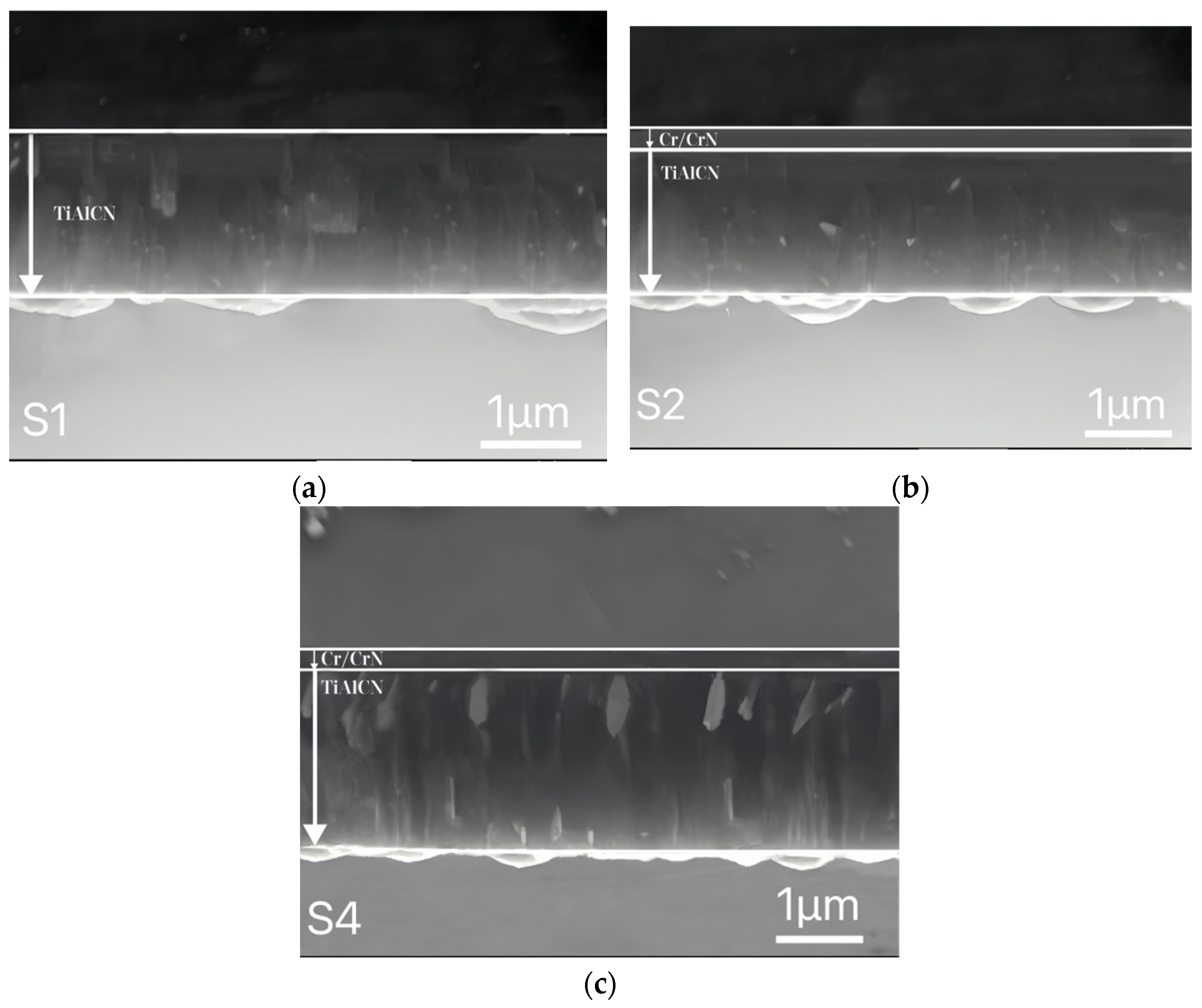
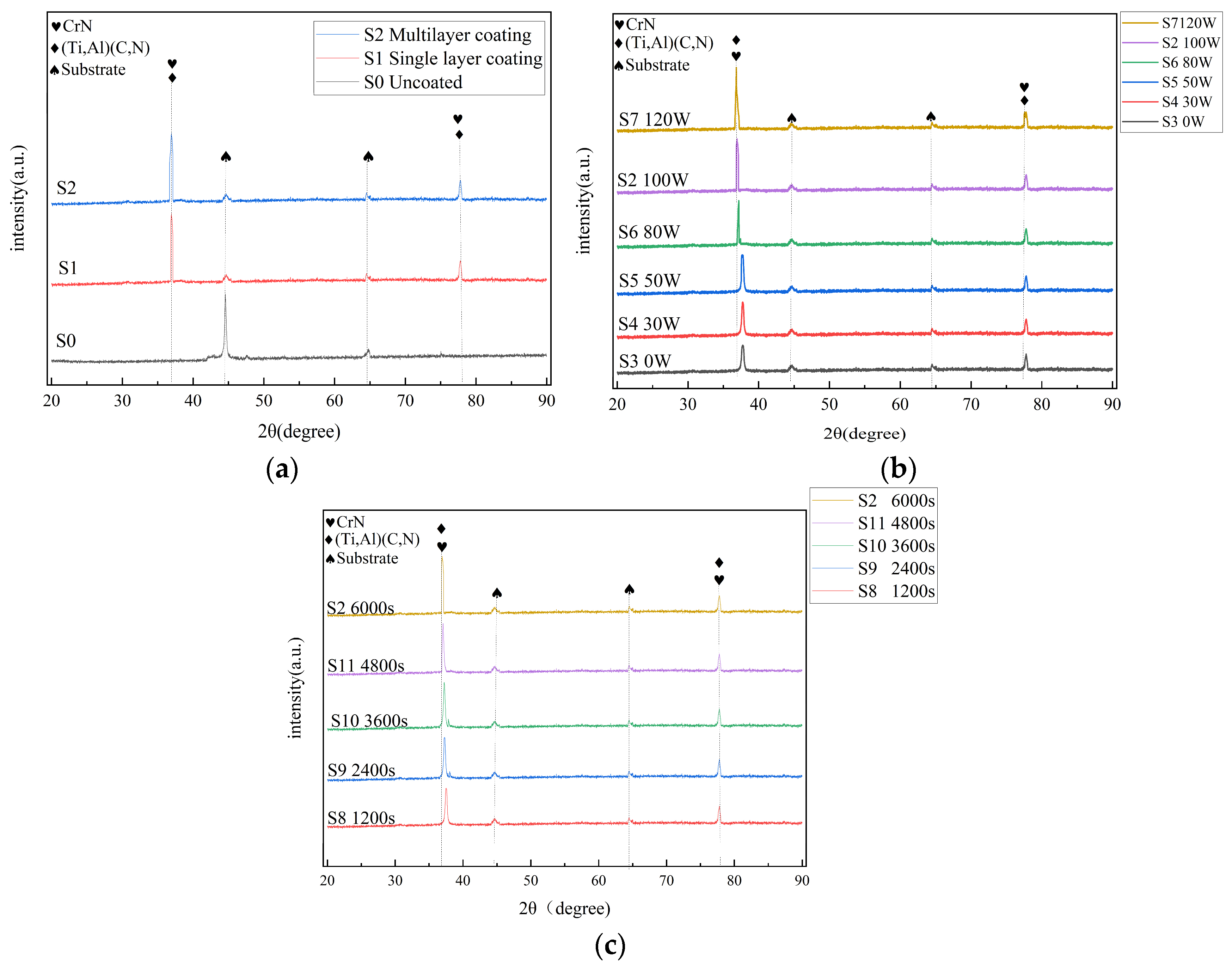
3.1. Morphology and Structure of the Coatings

In Figure 2d,f,i–l, it can be seen that after being magnified 1000 times, there were randomly distributed small defects, such as pits, particles, and pinholes, of different shapes and sizes on the surface of the coating. This was because during the DC sputtering process, the insulation layer on the target surface was continuously sputtered down by the accumulated positive charge, which could not react with ions in the plasma while flying towards the substrate, thus forming defects on the substrate surface [19]. The remaining coating surface had no obvious defects. Meanwhile, as shown in Figure 2g–l, it can be seen that as the carbon content increased, there were more small particles and pits on the surface of the coating. However, overall, the coating surface was smooth, dense, and flat, with good film quality, which proved that the surface morphology of the coating prepared on GCr15 bearing steel based on the magnetron sputtering technology studied here was good, effectively improving the surface defect problems that cannot be avoided with multi-arc ion plating, thermal spraying, and other traditional surface treatment technologies.
The relative elemental contents of the coating were measured using EDS, and the results are shown in Table 4. As the power to the graphite target rises and the coating duration extends, the carbon-to-nitrogen ratio in the coating progressively increases. This is due to the higher power elevating the energy of carbon within the target material. Additionally, prolonged coating times result in more carbon atoms being sputtered, leading to increased deposition on the substrate surface and consequently a higher carbon content in the coating. Concurrently, an excess of carbon atoms replaces nitrogen atoms, creating TiAlCN structures on the coating surface and elevating the carbon-to-nitrogen ratio.
Figure 3 shows the cross-sectional morphology of the coatings, where a represents the TiAlCN single-layer coating sample S1, b represents the Cr/CrN/TiAlCN multi-layer coating sample S2 at a graphite target power of 100 W, and c represents the multi-layer coating sample S4 at a graphite target power of 30 W. As shown in the figure, the cross-section of the coating was continuous and uniform, with no obvious defects, and it had a thickness of about 1.8 µm. In the figure, for b and c, it can be clearly seen that the coating had a two-layer structure. It was observed that there was a clear boundary between the TiAlCN layer and the Cr/CrN layer at the top layer, and the boundary between the Cr and CrN layers was not obvious due to the thin coating. When the carbon content was low at 4.85%, the columnar crystal structure of the TiAlCN layer was coarse. When the carbon content reached 11.37% (sample S2), the columnar crystal structure of the TiAlCN layer was weakened, and the microstructure became dense. This is due to the increased presence of the C element, which hinders grain growth and leads to grain refinement and reduced cylinder growth [12].
Figure 4 shows the X-ray diffraction patterns of the coatings. As shown in Figure 4a, except for the matrix diffraction peaks at around 44°and 64°, the coating mainly had two diffraction peaks. When the carbon content in Figure 4b was 0, the coating had a face-centered cubic structure and grew exponentially along multiple crystal faces. The diffraction peaks corresponding to the 37.6° and 77.8° accessories were (Ti, Al) (C, N) (111) and (311), respectively. When the graphite target material started sputtering, the addition of C replaced some N atoms, causing the diffraction peak of the coating to shift to the left. Meanwhile, with the increase in the C content and the extension of the coating time, the (111) diffraction peak intensity of the Cr/CrN/TiAlCN composite coating continuously increased, and the peak intensity of the (111) crystal plane was always higher than that of the (311) crystal plane. As can be seen from Figure 4c, the diffraction peak of the coating shifted as the coating time was extended, because more and more C atoms replaced N atoms in the coating as the coating time was extended, resulting in a leftward shift. This was because the (111) crystal plane usually had the smallest growth surface energy, and the crystal grew towards the crystal plane with a lower surface energy. Therefore, the coating exhibited a preferred orientation of the (111) crystal plane [20].

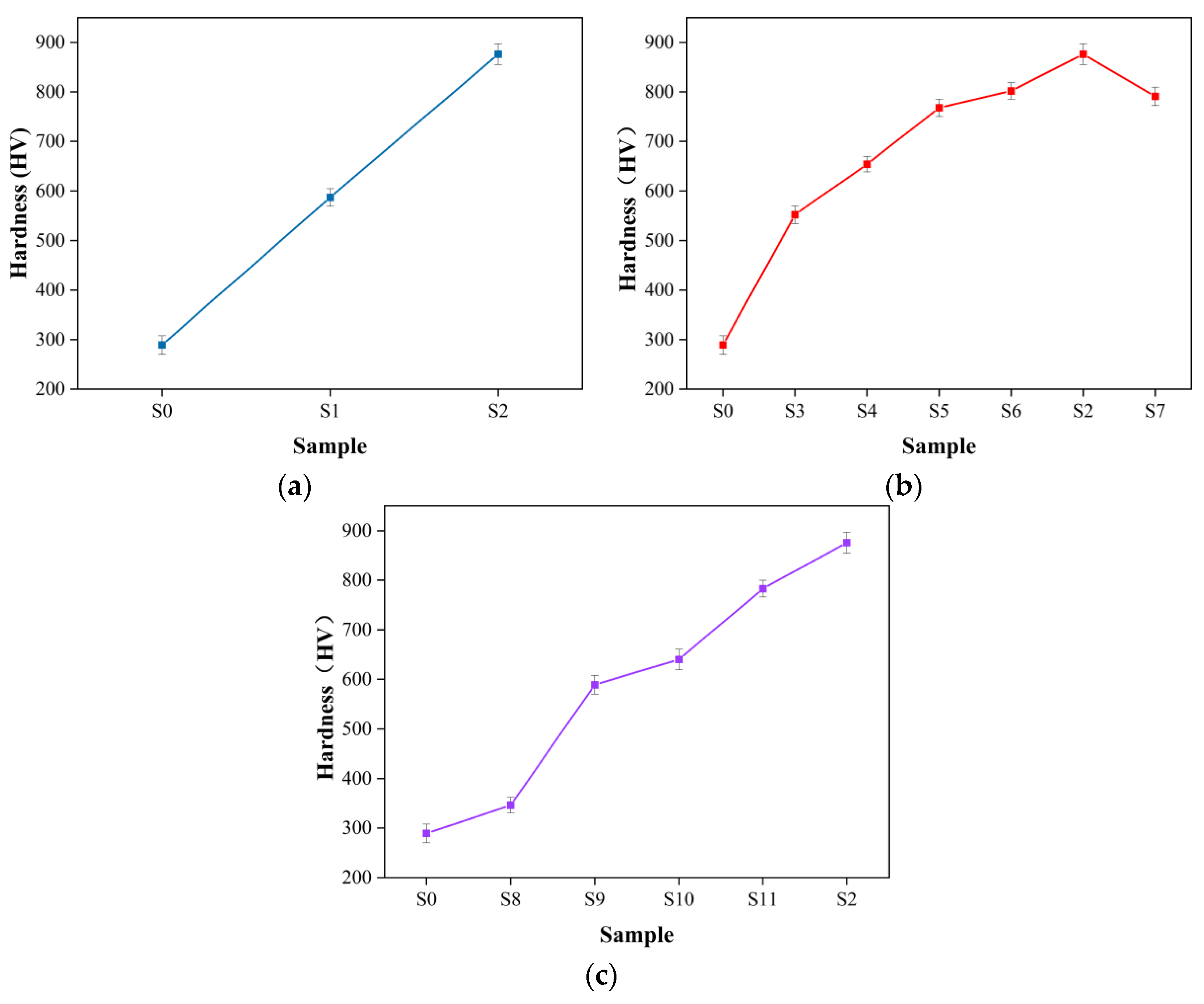
3.2. Mechanical Properties of the Coatings

Figure 5 shows an indentation diagram of the bonding performance of the coatings. There was a large amount of peeling at the edge of the indentation of the single-layer TiAlCN coating, as shown in Figure 5a. The card indicated level 3 failure, and its bonding performance was average. Under the same preparation conditions, the multi-layer Cr/CrN/TiAlCN composite coating had only slight cracks and no peeling at the edge of the indentation, indicating level 1 failure with good bonding performance. This was because the crystal structure of GCr15 bearing steel is a body-centered cubic system, which is composed of iron atoms and chromium atoms in the face-centered cubic, while, as shown in Figure 4, the crystal structure of the TiAlCN coating was mainly composed of face-centered cubic fcc—(Ti, Al) (C, N). The crystal structures of the two materials were different, and there was a significant difference in the atomic size, which could lead to lattice mismatch and unsynchronized crystal morphologies, resulting in poor membrane substrate adhesion. The transition layer could provide a buffering effect between the two, and the lattice structure transitioned relatively smoothly to reduce lattice mismatch and improve the compatibility of the two materials, thereby improving the bonding performance between the coating and the substrate [21]. The bonding performance is the most basic criterion for measuring whether a coating can be applied to a substrate. Only with a good bonding performance can the preparation of a coating have more practical significance. The innovative use of Cr/CrN as the transition layer between GCr15 bearing steel and the TiAlCN coating in this project improved the film-based adhesion, laying the foundation for the application and development of TiAlCN coatings deposited on GCr15 bearing steel in the future.
In Figure 5b,c, it can be seen that the peeling and cracking around the coating pits were obvious, indicating level 3 and level 4 peeling. This was because, in the case of a short coating time, the coating preparation was uneven, and there were more crystal defects at the bonding interface, resulting in a weak bonding force [22]. With the continuous increase in the coating time, the adhesion of the coating continued to improve, and the number of cracks at the edge of the indentation decreased, as shown in Figure 5d,e.
Figure 5g,h show the surface indentation morphologies of the coating when the graphite target power is 0 W and 50 W, respectively. It can be seen that when carbon was added, the morphology around the coating indentation was improved, and the bonding performance of the coating was enhanced. As the carbon content increased, as shown in Figure 5j–l, there were only small amounts of peeling and micro-cracks in the coating. With its level 1 and 2 peeling, the coating had excellent bonding performance. However, when the sputtering power of the target material exceeded a certain value, the energy of the ionized particles increased, leading to an increase in the substrate temperature, an increase in lattice defects in the coating, relaxation of internal stress, decreased adhesion, and decreased bonding performance [23], as shown in Figure 5g.
Figure 6 presents a schematic diagram of the microhardness of the coatings. As shown in Figure 6a, the hardness of the samples after no coating, single-layer coating, and multi-layer coating increased linearly. The deposition strengthening layer of the TiAlCN film significantly improved the hardness of the substrate, and adding Cr/CrN as a transition layer on this basis further improved the hardness of the coating. Correspondingly, adding a transition layer in the previous section improved the bonding performance of the coating, and the strength of the coating’s resistance to external forces was greater, resulting in higher hardness.
As the graphite target power increased, the coating hardness first increased and then decreased, as shown in Figure 6b. This was because TiAlN solidly dissolved into TiAlCN, forming an elastic strain field centered on C atoms. When dislocations moved near C atoms, the resistance increased, thus strengthening the thin film. Therefore, the hardness value of the TiAlCN coating was greater than that of the TiAlN coating. As the C content increased, more C elements were dissolved in TiAlN, strengthening and enhancing the hardness of the film. The microhardness of the TiAlCN film reached a maximum of 876 HV when the graphite target power was 100 W. However, when the sputtering power was too high, the surface temperature of the coating in the same section was too high, which led to a decrease in the bonding performance and thus affected the hardness of the coating.
As the coating time increased, the hardness of the coating continued to increase, as shown in Figure 6c. This was because the increase in sputtering time led to an increase in the deposition rate of the coating. Harder TiAlCN coatings were deposited on the substrate, and the thickness of the coating also increased, improving the hardness of the coating.

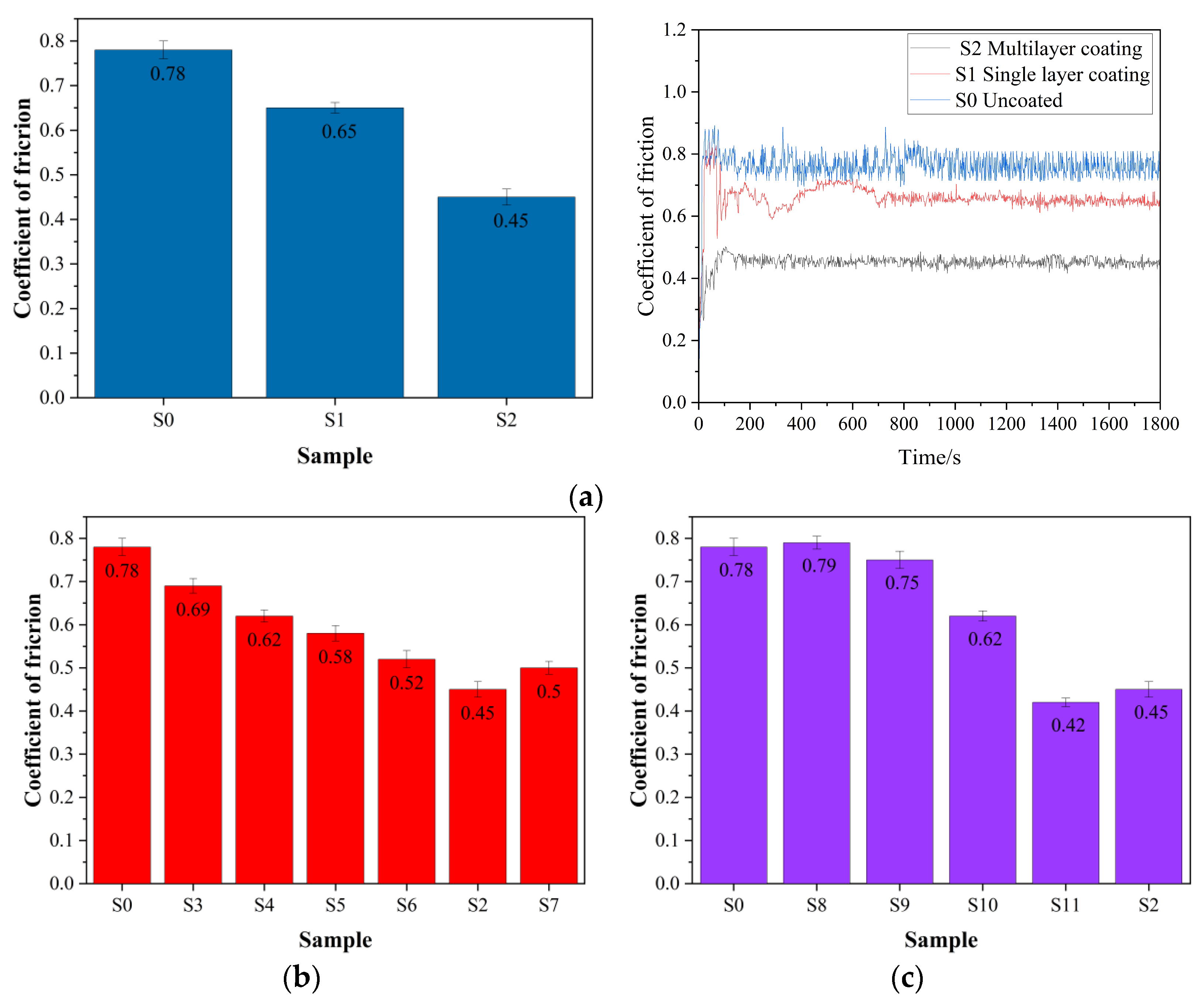
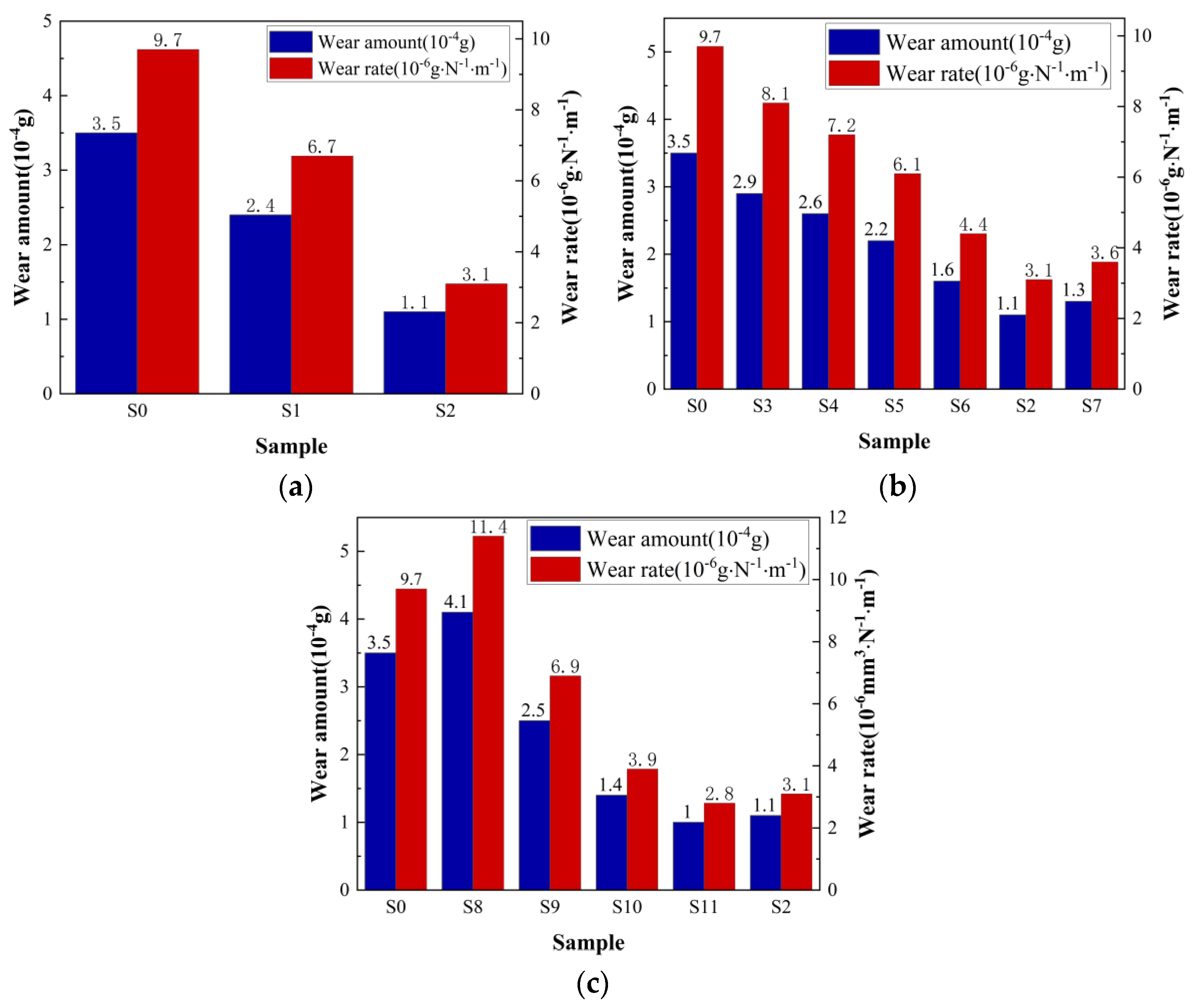
3.3. Friction and Wear Performance of the Coatings

Figure 7 shows a friction factor diagram of the coatings. In Figure 8a, it can be seen that the effect of using multiple layers on the friction coefficient of the coating was the same as that of hardness. Figure 8b reflects the effect of the graphite target power on the friction factor of the coating, indicating that the friction coefficient of the coating first decreased and then increased with the increase in the power. Figure 8c reflects the effect of the coating time on the friction coefficient of the coating. As the sputtering time increased, the friction coefficient of the coating also showed a trend of first decreasing and then increasing. When the coating time was 4800 s, the minimum friction coefficient of sample S11 was 0.42. When the sputtering time was too long, the structure of the coating could change, leading to surface oxidation or precipitation of other phases, thereby causing the friction coefficient to rise again. At the same time, if the coating time was too long, as described in the previous section, the surface roughness of the coating increased, and the friction and wear coefficients of the coating also increased. In summary, the friction coefficient of the coating first decreased and then increased with the extension of the coating time. At 4800 s, the friction coefficient was the smallest.
Table 5 shows the friction parameters of the coatings. Figure 8 shows the wear amount and wear rate of the coatings. As shown in the figure, under the same friction conditions, the wear of sample S1 with the single-layer TiAlCN coating decreased by 1.1 × 10⁻⁴ g compared with that of the uncoated sample S0, and the wear rate decreased by 30.1%. The wear of sample S2 with the multi-layer Cr/CrN/TiAlCN composite coating decreased by 2.4 × 10⁻⁴ g compared with that of the uncoated sample, and the wear rate decreased by 68%. This proved that TiAlCN is an excellent wear-resistant and wear-reducing coating for GCr15 bearing steel. Meanwhile, in the same friction environment, adding Cr/CrN as a transition layer between GCr15 bearing steel and the TiAlCN coating significantly reduced the wear. Placing the Cr/CrN/TiAlCN composite coating on GCr15 bearing steel was the best coating design solution.
The wear amount of the TiAlN coating deposited on GCr15 bearing steel was reduced by 0.6 × 10⁻⁴ g when compared with that of the uncoated bearing steel, and the wear rate was reduced by 16.5%, indicating that the TiAlN coating also had the function of wear resistance and wear reduction. When the carbon content in the coating was 4.85%, compared with that of the TiAlN coating, the wear amount was reduced by 0.3 × 10⁻⁴ g, and the wear rate was reduced by 11.1%. At the same time, the relationship between the friction coefficient, wear amount, and wear rate of the coating and the carbon content was the same as the relationship between the hardness and carbon content, which first decreased and then increased with the increase in the carbon content.
When the coating time was 1200 s, the wear amount of the coating was 4.1 g and the wear rate was 11.4 × 10⁻⁶ g/m·N, which were greater than the wear amount and wear rate of the uncoated bearing steel. If the coating time was too short, the coating appeared to undergo block-like detachment during friction and wear, and the wear amount increased. As the coating time increased, the wear amount, wear rate, and friction coefficient of the coating showed the same trend. When the coating time was 4800 s, the friction performance of the coating was optimal.

4. Conclusions

The main conclusions obtained through this experimental research were as follows.
(1)
This study innovatively added Cr/CrN as a transition layer in GCr15 bearing steel and TiAlCN to provide a buffering effect between the substrate and the coating, significantly improving the coating performance.
(2)
When the graphite target power was 0, the TiAlN coating showed a clear columnar crystal structure. After adding carbon atoms, the columnar crystal structure was weakened, and carbon atoms replaced nitrogen atoms, enhancing the mechanical and friction wear properties of the coating.
(3)
As the coating time increased, the roughness of the coating continuously changed, and the bonding performance and hardness continued to improve. The friction coefficient and wear parameters showed a trend of first decreasing and then increasing.
(4)
The optimal process parameters were a graphite target sputtering power of 100 W and a coating time of 4800 s. Compared with the uncoated GCr15 bearing steel, the coating hardness increased by two times after coating, the friction coefficient decreased by 0.36, the wear amount decreased by 2.5 × 10⁻⁴ g, and the wear rate decreased by 71%.
The results of this research provide an important basis for optimizing the process parameters of magnetron sputtering treatments on the surface of bearing steel, improving the service performance of GCr15 bearing steel components, and extending their service life, thereby saving costs in industrial production and creating greater economic value.

Author Contributions

Conceptualization, NY., F.L. and H.L.; Methodology, N.Y., Z.Z., M.S. and H.L.; Validation, Z.Z. and Y.C.; Data curation, Z.Z.; Writing—original draft, Z.Z.; Writing—review & editing, N.Y. and Z.Z. All authors have read and agreed to the published version of the manuscript.

Funding

This research received no external funding.

Institutional Review Board Statement

Not applicable.

Informed Consent Statement

Not applicable.

Data Availability Statement

Data are contained within the article.

Conflicts of Interest

The authors declare no conflicts of interest.

References

  1. Zhang, F.; Yang, Z. Development of and Perspective on High-Performance Nanostructured Bainitic Bearing Steel. Engineering 2019, 5, 319–328. [Google Scholar] [CrossRef]
  2. Peng, B.; Bi, Y.; Xue, B.; Zhang, M.; Wan, S. A Survey on Fault Diagnosis of Rolling Bearings. Algorithms 2022, 15, 347. [Google Scholar] [CrossRef]
  3. You, S.; Yi, X.; Yang, Q. Surface Modification and Reproduction—A New On-line Micro-remanufacturing Technology. In Proceedings of the Remanufacturing International Forum 2012, Beijing, China, 2 September 2012. [Google Scholar]
  4. Liu, X.-L.; Lin, Z.; Zhao, H.-J.; Sun, F. Study on Microstructure, Mechanical Properties, Tribological Properties and Service Performance of CrAlN and CrAlBN Coatings Deposited on Powder Metallurgy High-Speed Steel (PM-HSS) and Shaper Cutter by Arc Ion Plating Technique. Coatings 2024, 14, 486. [Google Scholar] [CrossRef]
  5. Biava, G.; de Araujo Fernandes Siqueira, I.B.; Vaz, R.F.; de Souza, G.B.; Jambo, H.C.M.; Szogyenyi, A.; Pukasiewicz, A.G.M. Evaluation of high temperature corrosion resistance of CrN, AlCrN, and TiAlN arc evaporation PVD coatings deposited on Waspaloy. Surf. Coat. Technol. 2022, 438, 128398. [Google Scholar] [CrossRef]
  6. Bilgin, S.; Güler, O.; Alver, Ü.; Erdemir, F.; Aslan, M. Effect of TiN, TiAlCN, AlCrN, and AlTiN ceramic coatings on corrosion behavior of tungsten carbide tool. J. Aust. Ceram. Soc. 2021, 57, 263–273. [Google Scholar] [CrossRef]
  7. Gopi, R.; Saravanan, I.; Devaraju, A.; Sivasamy, P. A Review on Recent Progress in PVD-TiN Coatings. Diffus. Found. Mater. Appl. 2023, 34, 41–53. [Google Scholar] [CrossRef]
  8. Zhao, J.; Liu, Z.; Wang, B.; Song, Q.; Ren, X.; Wan, Y. Effects of Al content in TiAlN coatings on tool wear and cutting temperature during dry machining IN718. Tribol. Int. 2022, 171, 107540. [Google Scholar] [CrossRef]
  9. Zhou, B.; Wang, Y.; Liu, Z.; Zhi, J.; Sun, H.; Wang, Y.; Wu, Y.; Hei, H.; Yu, S. Effect of modulation ratio on microstructure and tribological properties of TiAlN/TiAlCN multilayer coatings prepared by multi-excitation source plasma. Vacuum 2023, 211, 111917. [Google Scholar] [CrossRef]
  10. Wang, L.; Jiang, W.; Yang, Z.; Wang, X.; Lu, Y.; Lv, W. Joining mechanism between Al2O3–Ag–Cu–Ti composite coating and GCr15 substrate. Surf. Coat. Technol. 2013, 223, 98–103. [Google Scholar] [CrossRef]
  11. Liu, K.; Ma, F.; Lou, M.; Dong, M.; Zhu, Y.; Wang, Y.; Wu, X.; Liu, X.; Li, J. Structure and tribocorrosion behavior of TiAlCN coatings with different Al contents in artificial seawater by multi-arc ion plating. Surf. Topogr. Metrol. Prop. 2021, 9, 045004. [Google Scholar] [CrossRef]
  12. Chen, S.N.; Zhao, Y.M.; Zhang, Y.F.; Chen, L.; Liao, B.; Zhang, X.; Ouyang, X.P. Influence of carbon content on the structure and tribocorrosion properties of TiAlCN/TiAlN/TiAl multilayer composite coatings. Surf. Coat. Technol. 2021, 411, 126886. [Google Scholar]
  13. Zhang, G.-P.; Wang, X.-Q.; Lü, G.-H.; Zhou, L.; Huang, J.; Chen, W.; Yang, S.-Z. Effect of pulsed bias on the properties of ZrN/TiZrN films deposited by a cathodic vacuum arc. Chin. Phys. B 2013, 22, 035204. [Google Scholar] [CrossRef]
  14. Movassagh-Alanagh, F.; Mahdavi, M. Improving wear and corrosion resistance of AISI 304 stainless steel by a multilayered nanocomposite Ti/TiN/TiSiN coating. Surf. Interfaces 2020, 18, 100428. [Google Scholar] [CrossRef]
  15. Šnajdar, M.; Ćorić, D.; Sakoman, M. Comparative Study of Multilayer Hard Coatings Deposited on WC-Co Hardmetals. Coatings 2024, 14, 674. [Google Scholar] [CrossRef]
  16. Mori, T.; Noborisaka, M.; Watanabe, T.; Suzuki, T. Oxidation resistance and hardness of TiAlSiN/CrAlYN multilayer films deposited by the arc ion plating method. Surf. Coat. Technol. 2012, 213, 216–220. [Google Scholar] [CrossRef]
  17. Ghorbani, A.; Elmkhah, H.; Imantalab, O.; Meghdari, M.; Nouri, M.; Fattah-Alhosseini, A. The impact of mechanical post-treatment on the tribological and corrosion behavior of CrN/CrAlN coatings applied using the CAE-PVD technique. Appl. Surf. Sci. Adv. 2023, 18, 100477. [Google Scholar]
  18. Ali, L.A.; Dikici, B.; Aslan, N.; Yilmazer, Y.; Sen, A.; Yilmazer, H.; Niinomi, M. In-vitro corrosion and surface properties of PVD-coated β-type TNTZ alloys for potential usage as biomaterials: Investigating the hardness, adhesion, and antibacterial properties of TiN, ZrN, and CrN film. Surf. Coat. Technol. 2023, 466, 129624. [Google Scholar]
  19. Ramos, A.S.; Simões, S.; Maj, L.; Morgiel, J.; Vieira, M.T. Effect of Deposition Parameters on the Reactivity of Al/Ni Multilayer Thin Films. Coatings 2020, 10, 721. [Google Scholar] [CrossRef]
  20. Huang, Y.Z.; Stueber, M.; Hovsepian, P. The significance of carbon on the microstructure of TiAlN-C coatings deposited by reactive magnetron sputtering. Appl. Surf. Sci. 2006, 253, 2470–2473. [Google Scholar] [CrossRef]
  21. Harani, S.G.; Sumitra, S. Magnetron Sputtered Thin Films Based on Transition Metal Nitride: Structure and Properties. Phys. Status Solidi 2022, 220, 2200229. [Google Scholar]
  22. Sin, N.D.M.; Mamat, M.H.; Rusop, M. Effect of Deposition Time on Properties of Nanostructured ZnO Thin Films Deposited by RF Magnetron Sputtering. Adv. Mater. Res. 2013, 832, 460–465. [Google Scholar] [CrossRef]
  23. Ma, D.; Deng, Q.; Liu, H.; Leng, Y. Effect of Ion Energy on the Microstructure and Properties of Titanium Nitride Thin Films Deposited by High Power Pulsed Magnetron Sputtering. Coatings 2021, 11, 579. [Google Scholar] [CrossRef]
Figure 1. Diagram of the standard indentation card.
Coatings 14 00782 g001
Figure 2. Morphology of the coating as determined with an SEM: (a) S1; (b) S8; (c) S9; (d) S10; (e) S11; (f) S2; (g) S1; (h) S3; (i) S4; (j) S5; (k) S2; (l) S6.
Coatings 14 00782 g002aCoatings 14 00782 g002b
Figure 3. Cross-sectional morphology of the coating: (a) cross-sectional view of the single-layer coating (S1); (b) cross-sectional view of a multi-layer coating (S2); (c) cross-sectional view of a multi-layer coating (S4).
Coatings 14 00782 g003
Figure 4. XRD patterns of the coatings: (a) number of layers; (b) graphite target power; (c) coating time.
Coatings 14 00782 g004
Figure 5. Indentation diagram of the coatings: (a) S1; (b) S8; (c) S9; (d) S10; (e) S11; (f) S2; (g) S3; (h) S4; (i) S5; (j) S6; (k) S2; (l) S7.
Coatings 14 00782 g005
Figure 6. Microhardness of the coatings: (a) number of layers; (b) graphite target power; (c) coating time.
Coatings 14 00782 g006
Figure 7. Friction coefficient diagram of the coatings: (a) number of layers; (b) graphite target power; (c) coating time.
Coatings 14 00782 g007
Figure 8. Schematic diagram of the wear amount and wear rate of the coatings: (a) number of layers; (b) graphite target power; (c) coating time.
Coatings 14 00782 g008
Table 1. Chemical composition of GCr15 bearing steel.
ElementCrCMnSiPS
Content (wt.%)1.30–1.650.95–1.050.20–0.400.15–0.35≤0.027≤0.020
Table 2. Process parameters.
Process Parameters
CoatingCrCrNTiAlCN
Background vacuum degree (GPa)8 × 10−48 × 10−48 × 10−4
Working air pressure (Pa)111
Coating power (W)Cr:100Cr:100TiAl: 110 Graphite: 0–120
Coating time (s)3006001200, 2400, 3600, 4800, 6000
Ar2 flow (sccm)906060
N2 flow (sccm)05050
Table 3. Experimental plan.
SampleGraphite Target Power (W)Coating Time (s)Number of Layers
S0000
S110060001
S210060003
S3060003
S43060003
S55060003
S68060003
S712060003
S810012003
S910024003
S1010036003
S1110048003
Table 4. Table of the relative elemental contents of the coatings.
SampleCr/at.%Ti/at.%Al/at.%C/at.%N/at.%
S1018.0421.7312.0348.20
S214.8615.3019.3811.3739.09
S317.3217.6121.74045.33
S416.9518.3719.094.8542.74
S515.5915.0120.526.9741.91
S614.5316.3119.949.7639.46
S715.2013.8617.0913.0338.82
S832.835.277.288.2546.37
S925.467.099.939.9347.59
S1021.099.9112.179.0247.89
S1117.2612.9313.8810.1645.77
Table 5. Friction parameters of the coatings.
Samplem1 (g)m2 (g)M (10−4 g)L (m)S (N)W (10−6 g/N.m)Average
Coefficient of Friction
S036.0833236.082973.5361 9.70.78
S136.1847136.184472.43616.70.65
S236.1742536.174141.13613.10.45
S336.1653236.165032.93618.10.69
S436.1740636.173802.63617.20.62
S536.1751736.174952.23616.10.58
S636.0542836.174951.63614.40.52
S736.1508536.150721.33613.60.5
S836.2359436.235434.136111.40.79
S936.2007636.200512.53616.90.75
S1036.1752336.175091.43613.90.62
S1136.1536736.153571.03612.80.42
Disclaimer/Publisher’s Note: The statements, opinions and data contained in all publications are solely those of the individual author(s) and contributor(s) and not of MDPI and/or the editor(s). MDPI and/or the editor(s) disclaim responsibility for any injury to people or property resulting from any ideas, methods, instructions or products referred to in the content.

