1. Introduction
Coating layer technologies are generally used to improve surface hardness, wear strength, thermal resistance, contact friction, with applications in the cutting tool and gas turbine industry [
1,
2,
3,
4,
5,
6]. Since mainly impulsive, high surface contact forces are expected to be applied to cutting tool components, coating toughness is a major requirement. Plasma Vapour Deposition (PVD) techniques and Chemical Vapour Deposition (CVD) techniques are mainly used in this context [
3], generating high residual stresses at the interface between the coating layer and the substrate. In operating conditions, the combination of residual and working load generated stresses can produce coating peeling and surface cracks [
2] that compromise the effectiveness of the coating treatment. Coating toughness and maximization of the coating adhesion properties are also a major requirement in other mechanical contexts such as Micro Electro-Mechanical Systems (MEMS) devices, where mainly large flexural displacements and strains, and by consequence high surface stresses, are expected [
7]. Residual stress evaluation at the experimental and at the design stage is generally required in this context, and experimental nano-indentation techniques [
8,
9] and model-based techniques [
7] are known.
Coatings can also be employed to increase the global dissipative properties of an industrial component with limited influence on the other mechanical properties [
10,
11,
12]. Mechanical components with high stiffness, resistance and vibration damping specifications are in great demand for most aerospace, automotive and automation industrial mechanical applications, and some composite solutions are suitable to design components with these properties. In modern high-speed applications, unwanted vibrations may result due to high inertial forces. A vibrational response associated to a small displacement and deformation field but to a wide frequency range may cause an excessive noise level, a decrease in the system efficiency and a shortening of the system service life. By increasing the component dissipative properties, high vibration levels of the contact-free, external surface of thin walled mechanical components such as a mechanical pump, motor or gearing casing may be effectively damped.
Single or multiple layers of a coating material can be deposited or grown in order to produce a finished composite component with specifically designed characteristics including vibrational damping capability. Many different techniques are known [
13,
14] and in this work specimens obtained by means of the screen printing technology, mainly residual stress free, are compared.
The coating material structure [
15,
16,
17], the interface structure [
18], the temperature dependence [
19] are all factors that must be taken into account when studying the influence of coatings on the coated component damping behaviour. The coated component dissipative properties can be significantly tailored by means of the application of coating layers showing high internal hysteresis or with high frictional actions at the interface between the different layers [
15,
20,
21]. Experimental research done by these authors [
22,
23] and other researchers [
13,
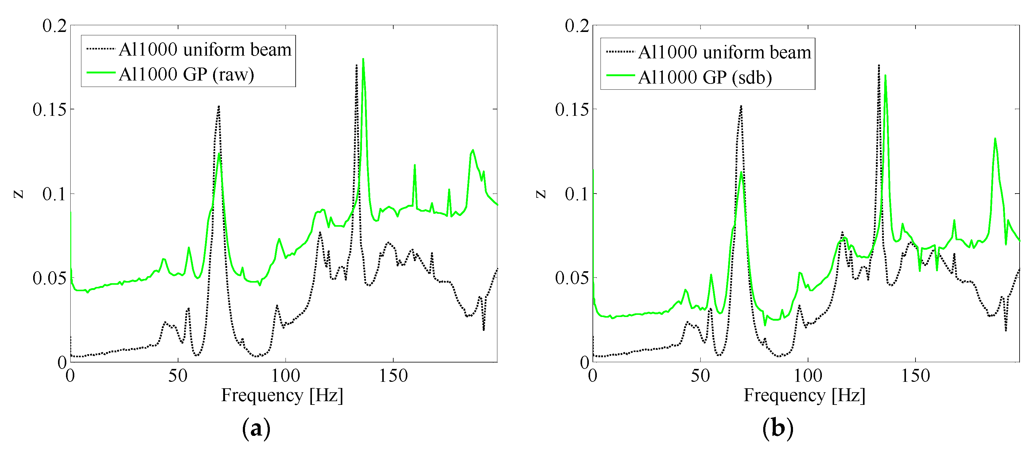
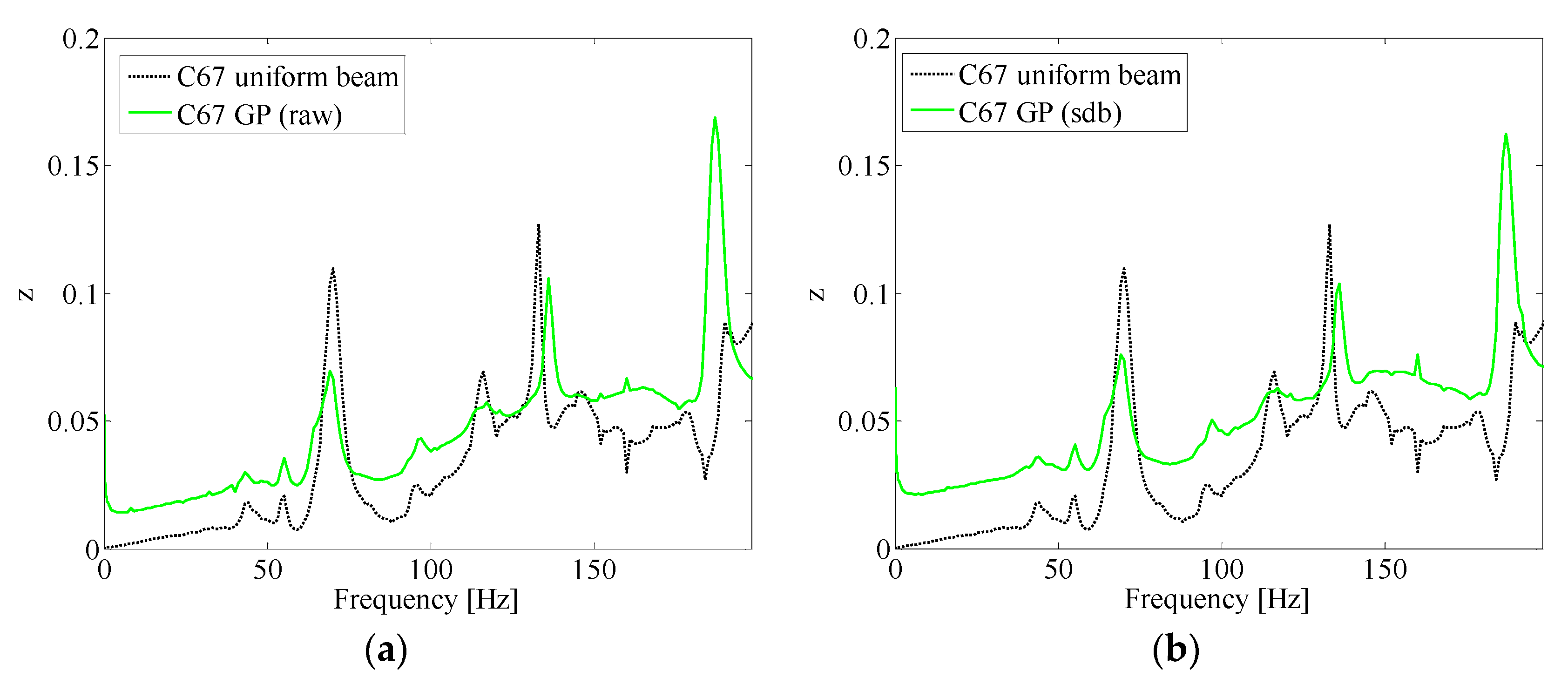
24] outlined that the application of some coating surface solutions on thin-walled components can increase the vibration damping behaviour, and that this result is mainly due to dissipative actions originating at the interface between the substrate and the coating layer. It is known from literature that dynamic mechanical measurements are an effective experimental tool to study the damping behaviour of coated components and that both forced and free vibrations tests were employed to estimate the dissipative properties of a wide range of coating materials and component geometries by means of comparing the coated and uncoated component dynamical response [
25,
26,
27]. In this work, the damping behaviour of different coating solutions applied on two different metal substrates, i.e., harmonic steel and Al alloy, are compared. Coated and uncoated specimen dynamic mechanical measurement test results are processed by means of a robust parameter identification and model condensation technique to investigate the effectiveness of the different solutions.
A multi layered beam model, taking into account the frictional actions localized at the interface between the layers, is proposed to help virtually test and find optimal coating solutions, to be applied to a mechanical system casing and to thin-walled components to be used in the high speed automation industry, in order to damp vibration and noise generated in working conditions. Dissipative actions are modeled by relaxing the kinematical displacement continuity at the layer interface and by introducing complex elasto-hysteretic dynamical interface coupling. The effects on the dissipative properties of the distributed constraints modeling boundary conditions are also taken into account. The model is based on zig-zag multi-layer beam theories [
28,
29,
30], and on layer wise beam theories [
31]. High order layer wise beam theories are obtained by modifying the classic Bernoulli-Euler and Timoshenko beam theories in order to deal with composite beams with numerous layers in which the mechanical and geometrical characteristics significantly vary from layer to layer. The advantage of zig-zag theories with respect to other layer wise theories is that the number of state space variables required by the model is low and does not depend on the number of layers. Since large residual stress free, amorphous based structure coatings, mainly deposited by screen printing technologies, are considered in this work, no account is given here with respect to experimental measuring and modeling of residual stresses generated at the interface between two different layers.
2. Damping-Oriented Coating Solutions
In this work three innovative, different coating solutions, applied to a slender beam, uniform rectangular cross section test specimen, are compared. Both homogeneous and composite specimens are taken into account. Two different types of metallic substrates are considered, harmonic steel (C67) and Al alloy (Al1000).
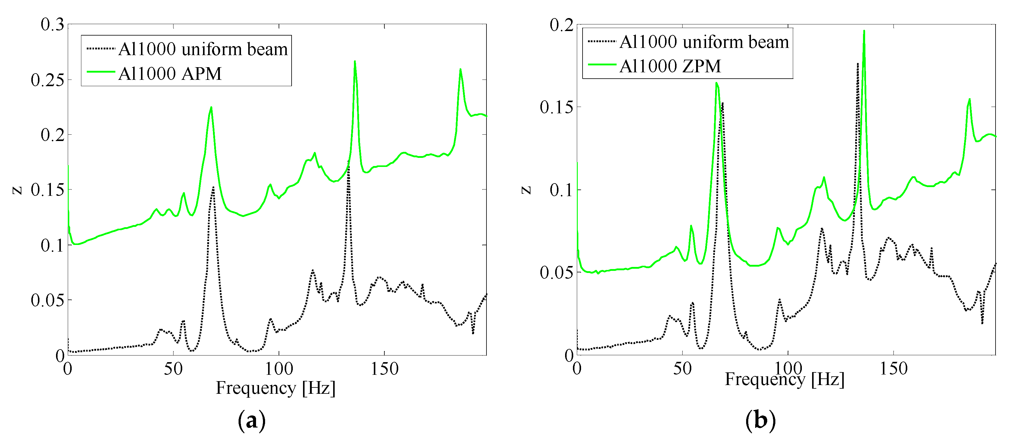
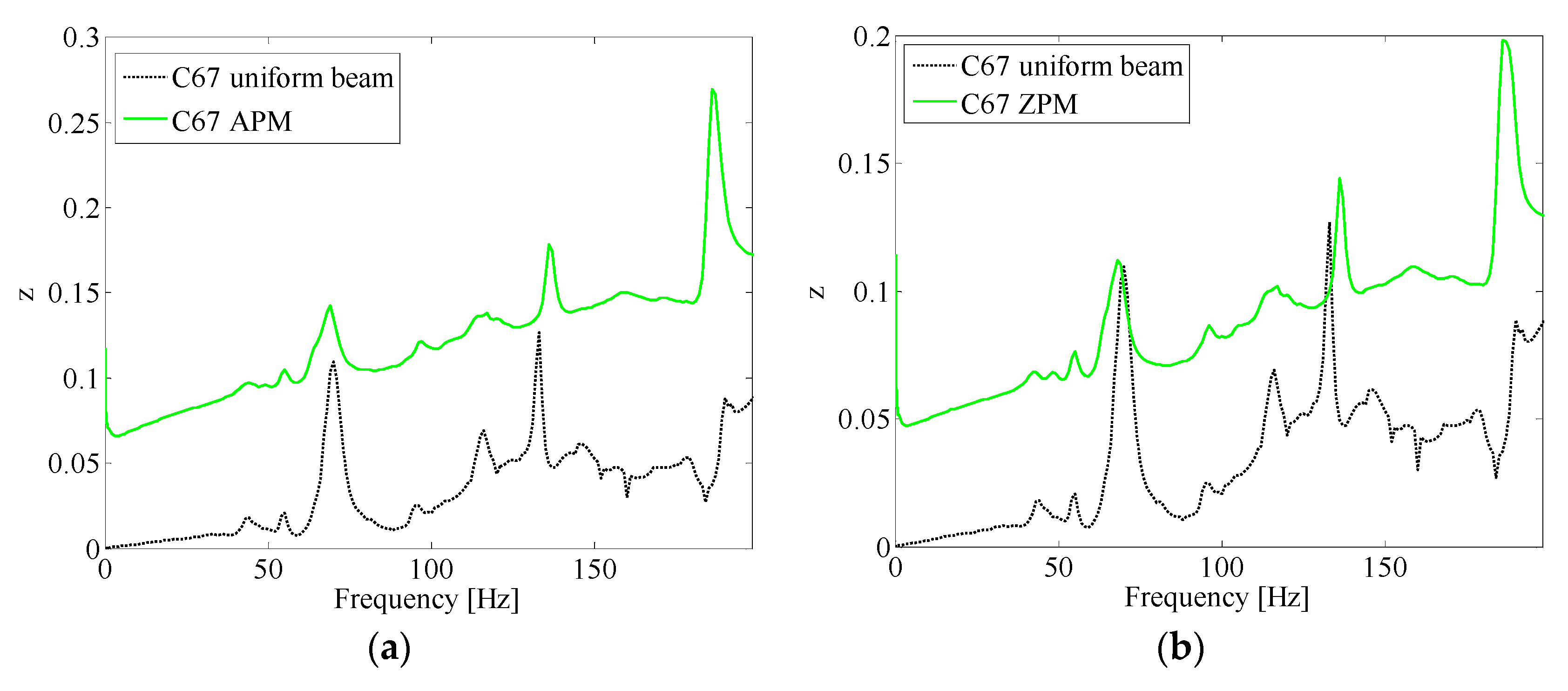
Three ceramic coating solutions are proposed, i.e., an alkali activated geopolymer (GP), an alkali activated alumina powder mixture (APM), an alkali activated zirconia powder mixture (ZPM). Ceramic materials, in comparison to metals and polymers, may present superior mechanical, chemical and thermal resistance properties [
32].
2.1. GP Solution
The geopolymer solution is made by mixing of a commercial metakaolin powder (base) with an aqueous basis binder (activator) prepared from a potassium-hydroxide solution in H
2O with pyrogenic silica solution. The chemical composition of the resulting solution is reported in
Table 1.
Potassium was preferred to sodium in the alkaline activator since a better degree of polycondensation can be achieved and because of its ability to provide geopolymeric structures, associated with high mechanical strength [
33]. Geopolymers are inorganic polymers formed by linear chains or tridimensional arrays of SiO
4 and AlO
4 tetrahedra [
34]. The geopolymer is produced by mechanical mixing (planetary centrifugal mixer “Thiky Mixer” ARE 500 by THINKY, Tokyo, Japan) of a reactive powder base (Metakaolin Argical M 1200S, IMERYS, Cornwall, UK) with an aqueous basis activator (H
2O solution with potassium-hydroxide of 85% purity and an addition of a 99.8% purity pyrogenic silica solution). The prepared geopolymer has a 2.83 Si/Al ratio composition [
34] and is applied to the upper and lower surfaces of the substrate beam by means of screen printing.
2.2. APM and ZPM Solutions
The APM solution is made by mixing of alumina powder, particle size 0.5 μm, with the activator defined in
Table 1, mass ratio between alumina powder and activator being 1/1. The ZPM solution is made by mixing of a zirconia powder, particle size 0.4 μm, with the activator defined in
Table 1, mass ratio between Zr powder and activator being 1/1.
The composite coatings result in a paste-like solution, and consolidation reactions then follow because of dehydration of the APM and ZPM solutions. Mechanical strength results from the chemical bonds between the basic potassium silicate in alkali solution chains and the acid alumina and zirconia powders.
2.3. Specimens Preparation
Eight composite components are obtained by applying coating layers on the two opposite faces of the beam substrate. The specimen geometry specifications are length (11.0 ± 0.01) × 10−3 m, thickness (0.5 ± 0.01) × 10−3 m and width (3.0 ± 0.01) × 10−3 m.
Specimen data are reported in
Table 2, including the specimen label, the substrate and the coating layer material, the production technique, and the coating layer thickness.
Table 1 label “raw” indicates that the surface substrate is unfinished, texture
Ra 0.8, while “sdb” label refers to a sandblasted surface substrate, texture
Ra 12. After applying the GP, APM and ZPM coatings to the metal substrates, all samples were cured at
T = 25 °C for 9 days, in order to increase the adhesion behaviour [
35].
According to known literature [
35,
36], a geopolymer cured at room temperature tends to slowly change its structure and presents a low porosity and a high toughness while when cured at a higher temperature it exhibits faster structure changes, higher porosity and lower toughness.
In previous works [
22,
23], TiO
2 and Al
2O
3 based coatings were considered, but the results did not show a meaningful improvement with respect to the uncoated beam specimen, concerning both vibration damping behaviour and adhesion strength in cyclic loading condition. In this contribution, new layer technologies based on a screen printing production process and inorganic polymer based composite material solutions, are taken into account.
2.4. Optical and SEM Specimen Structural Characterization
The coating structure and the coating-substrate interface is analyzed by means of optical and scanning electron microscopy (SEM). Samples were fracture cut in the transverse cross section, in order to expose the whole cross section. Before optical investigation, the specimen cross sections were embedded in epoxy resin and polished with abrasive SiC paper up to 2500 mesh and then by using a diamond based, 0.5 μm particle size, lapping paste. Chemical etching (Ethanol added to 3% HNO3 at 150 °C) then follows.
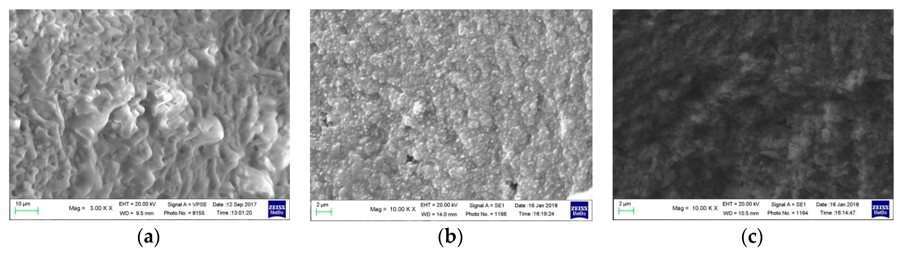
Figure 1a–c report the SEM images related to the three coatings solutions proposed. All coatings present a typical composite structure, showing: geopolymer and unreacted potassium silicate (
Figure 1a), the potassium silicate as matrix and fine alumina dispersed particles (
Figure 1b), the potassium silicate as matrix and zirconia dispersed particles (
Figure 1c). In
Figure 1b the 0.5 μm particle size is observed and the almost total absence of shrinkage and solidification defects to form rigid structures, possibly associated to big strength characteristics, is also outlined. In
Figure 1c, the size of zirconia powder is difficult to evaluate because of the resulting irregular morphology with brittle fragments of consolidate and dehydrate potassium silicate.
Figure 1a, referring to the geopolymeric coating, shows a compacted interconnected microstructure which can increase toughness and strength in comparison to the other coatings considered. The amorphous nature of these coatings may greatly influence the stress state of consolidate coatings, so that there are no detectable cracks and microcracks that could compromise the performance of the coatings when subjected to mechanical strain vibrations, because no differences induced by thermal and mechanical stresses into the polycrystalline state are expected to appear in working conditions.
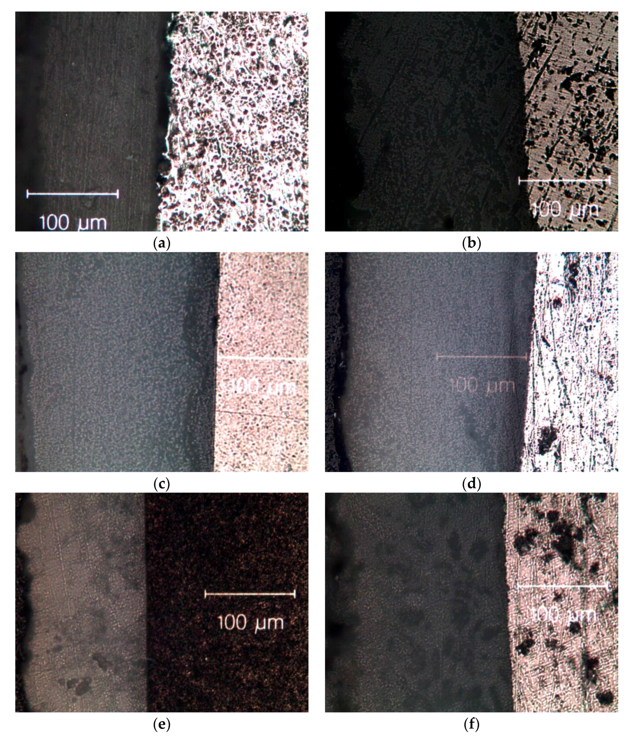
Figure 2a–f report the optical images related to the interface obtained by means of the three coatings solutions and two metal substrates investigated. As shown, there is an evident adhesion between ceramic coatings and the metal substrate.
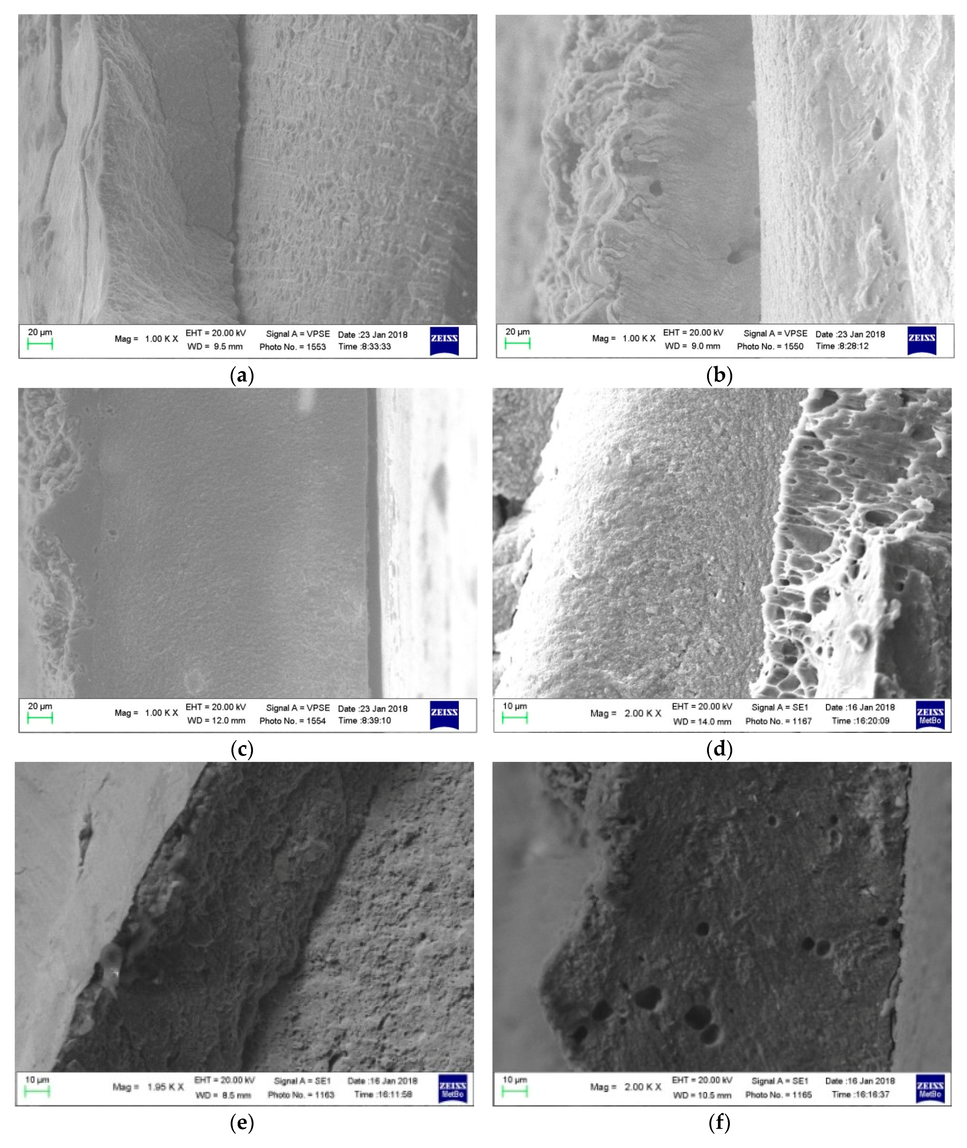
Figure 3a–f report the SEM images related to the interface obtained by means of the three coatings solutions and two metal substrates investigated. Defects by shrinkage phenomena at the metal coating interface are not shown. It can be outlined that the adhesion between the proposed coating solutions and the Al1000 substrate appears to be more effective than with respect to the C67 substrate.
3. Identification Procedure
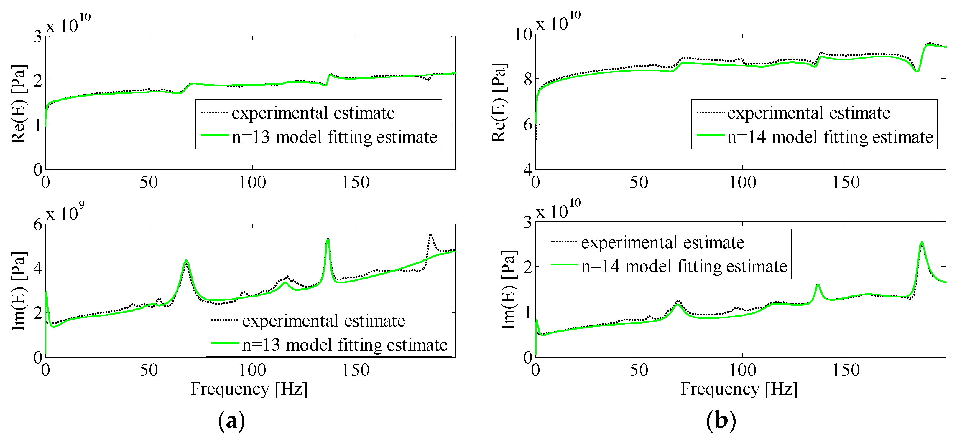
In this work, applied force and displacement data obtained by means of dynamic mechanical measurements over a wide frequency range are used to estimate the complex modulus
E(
ω) of measured beam specimens. The values of
E(
jω) are estimated by means of a procedure fully defined by the authors of this work in a previous paper [
29] and are here briefly outlined.
E(
jω) defines the specimen stress (
)-strain (
) equivalent material relationship in the frequency domain (Equation (1)):
Slender beams of uniform rectangular cross section with clamped sliding boundary conditions are considered. The contribution of the inertial actions is also taken into account.
The complex, experimentally estimated values of
at frequencies
ωi are found by finding the solutions of Equation (2) by means of the Newton Raphson method, starting from known static modulus
E0 =
E(
jω = 0):
and
are respectively the measured transverse displacement and applied periodic force (at frequency
ωi) at the beam sliding end.
M is the beam mass,
I is the beam section moment,
L is the beam length and
ks are the roots of
.
A specific robust identification and condensation procedure [
37] is applied on the
E(
jω) experimentally estimated values to identify the specimens stress-strain relationship in the frequency domain.
E(
jω) (Equation (1)) is modeled by means of a high order generalized Kelvin model and its parameters are identified. The global model order can be condensed to obtain a new model of comparable accuracy but significantly lower order.
5. Modeling of Multi-Layer Coated Beam Composites
5.1. Motivations
The contribution of interface dissipative actions to the damping behaviour of coated components is clearly outlined from the results presented in the previous sections. Nevertheless, while the procedure used to obtain the condensed, generalized standard linear solid model E(jω) may be indeed effective to estimate the damping properties of different specimens and to compare them, it cannot be used to design and predict the damping behaviour of new, not previously tested, coating solutions. An effective model must be able to take into account the coating solution architecture, i.e., the number of layers, the thickness, the material and the coating technology adopted for the different layers as well.
In literature many models are known for multi-layered beams and plates [
29,
39,
40,
41,
42,
43,
44] but no attempts can be found with respect to modelling the interface dissipative actions. In this section, a multi-layered beam model based on zig-zag beam and plates theory addressing this issue is presented. The model takes into account the layers of geometric and material properties and is able to deal with interface slipping and local friction. The model uses an elasto-hysteretic contribution to define the dissipative actions at the interface between the layers.
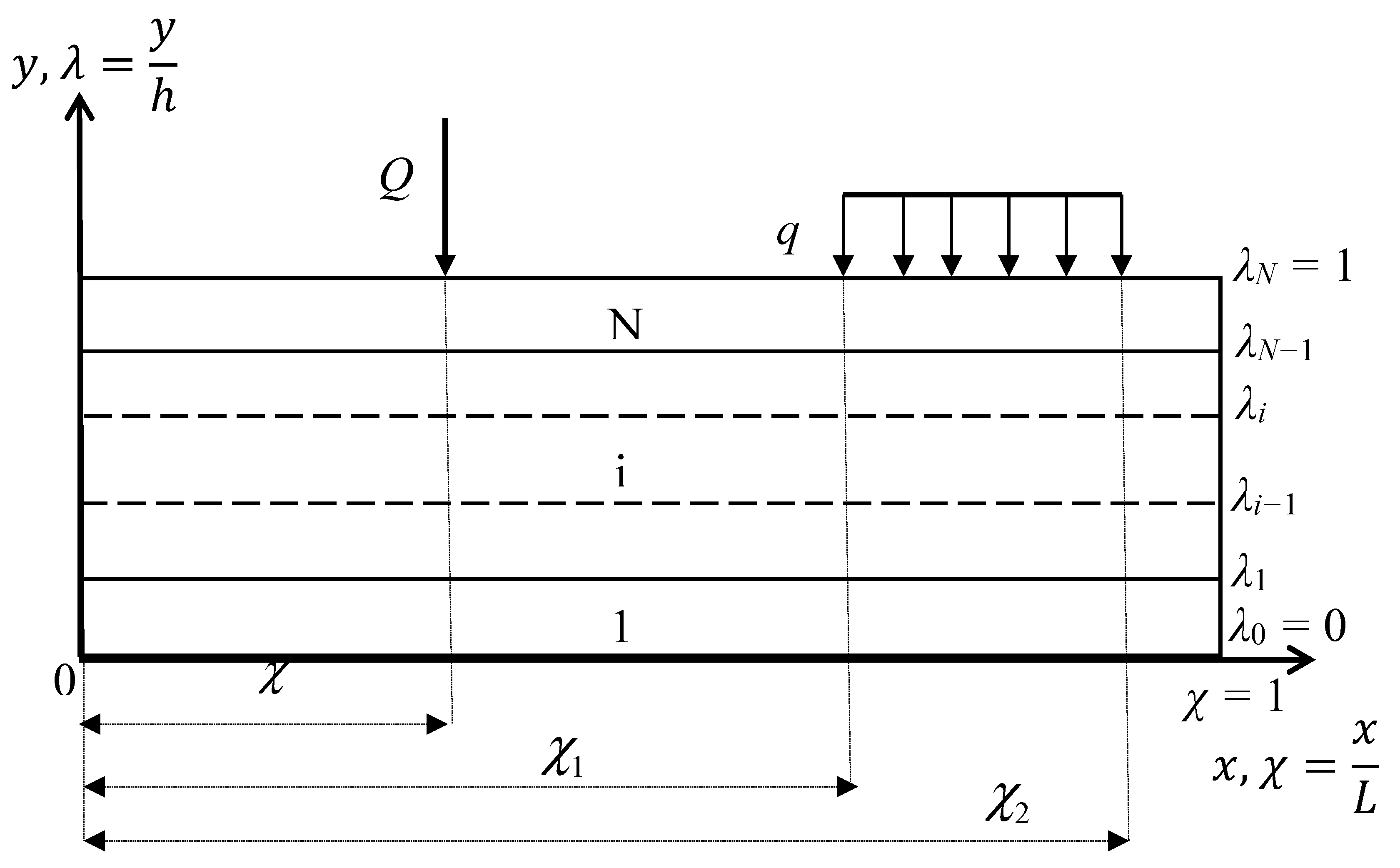
5.2. Multi-Layer Beam Flexural Model
A schematic representation of a multi-layered beam model is reported in
Figure 11. A multi-layered beam made up of
N layers and with uniform rectangular section is considered.
L,
g,
h, are respectively the beam length, width and thickness,
,
ρi is the
i-th layer density. In each layer (
i = 1, …,
N), the material constitutive equations are assumed to be:
where
Ei and
Gi are the
i-th layer longitudinal and shear elastic moduli,
σ =
σxx and
τ =
τxy are the flexural stress and shear stress components,
ε =
εxx and
γ =
γxy are the strain components. Since small displacement and deformation fields are considered, transverse displacement
is assumed as being stationary with respect to
y,
λ. Transverse and longitudinal displacement
,
are assumed as follows:
The following 2×
N + 3 state variables result:
The kinematical relationships between strain and displacement components is assumed to be:
where
.
N + 1 equilibrium conditions at the layer interfaces hold:
where
From Equations (6), (8) and (9), a system of
N − 1 equations can be obtained:
By equating the Equation (10) right side sum to Equation (10) left side sum, and taking into account of Equation (9):
c is a stationary value defined by the shear moduli and thickness values of the beam layers. By defining the following variable change:
Putting Equations (10)–(12), the following iterative formula results:
Now by relaxing the continuity of the kinematical
u component at
λ = λi interface, the longitudinal sliding
at the interface is:
At
λ = λi interface, an elasto-hysteretic constitutive relationship is assumed by means of complex impedance
:
where
. Defining the following variable change:
the values of
ai from the following iterative formula, obtained by combining Equations (3), (14) and (15):
From Equations (11), (13) and (17), stationary
,
,
, values result. Only three independent state variables, collected in vector
X, result:
The following expression of the kinematical components result:
5.3. Equation of Motion
To obtain the equation of motion, the system total potential energy (Π) is considered:
U is the contribution of the internal elasto-hysteretic actions:
WI is the contribution of the inertial actions:
where
.
WE is the contribution of the external forces:
where
Q is a lumped force applied at
and
q is a distributed pressure applied at
.
is the contribution of the distributed, viscous elastic, constraints modeling boundary conditions:
where
and
Kw,
Ku,
Cw,
Cu, are the constraint elastic and viscous parameters respectively. It is assumed that the state unknown solution variables of Equation (18) satisfy:
and generally unknown functions
αr are restricted to a set of known harmonic functions:
And using Equations (23) and (27):
where:
Using Equations (26)–(29), from Equations (21)–(24) results:
and the resulting equation of motion is:
Because of the elasto-hysteretic assumption (Equation (15)), complex
Mu,
ΔCu,
Kε,
ΔKu matrices result. To find the beam frequency response function
, i.e., the complex transverse response
related to unitary, lumped, harmonic excitation at frequency
ω applied at abscissa
χq, the following procedure is applied. Both sides of Equation (35) are Fourier transformed (
)
The frequency response function matrix
F(
jω) is:
Equation (37) can be expressed as:
Pre-multiplying both sides of Equation (39) by
:
With further manipulation of Equation (40):
In Equation (41)
F0 can be expressed in closed form by means of modal decomposition [
45]. The beam frequency response function is:
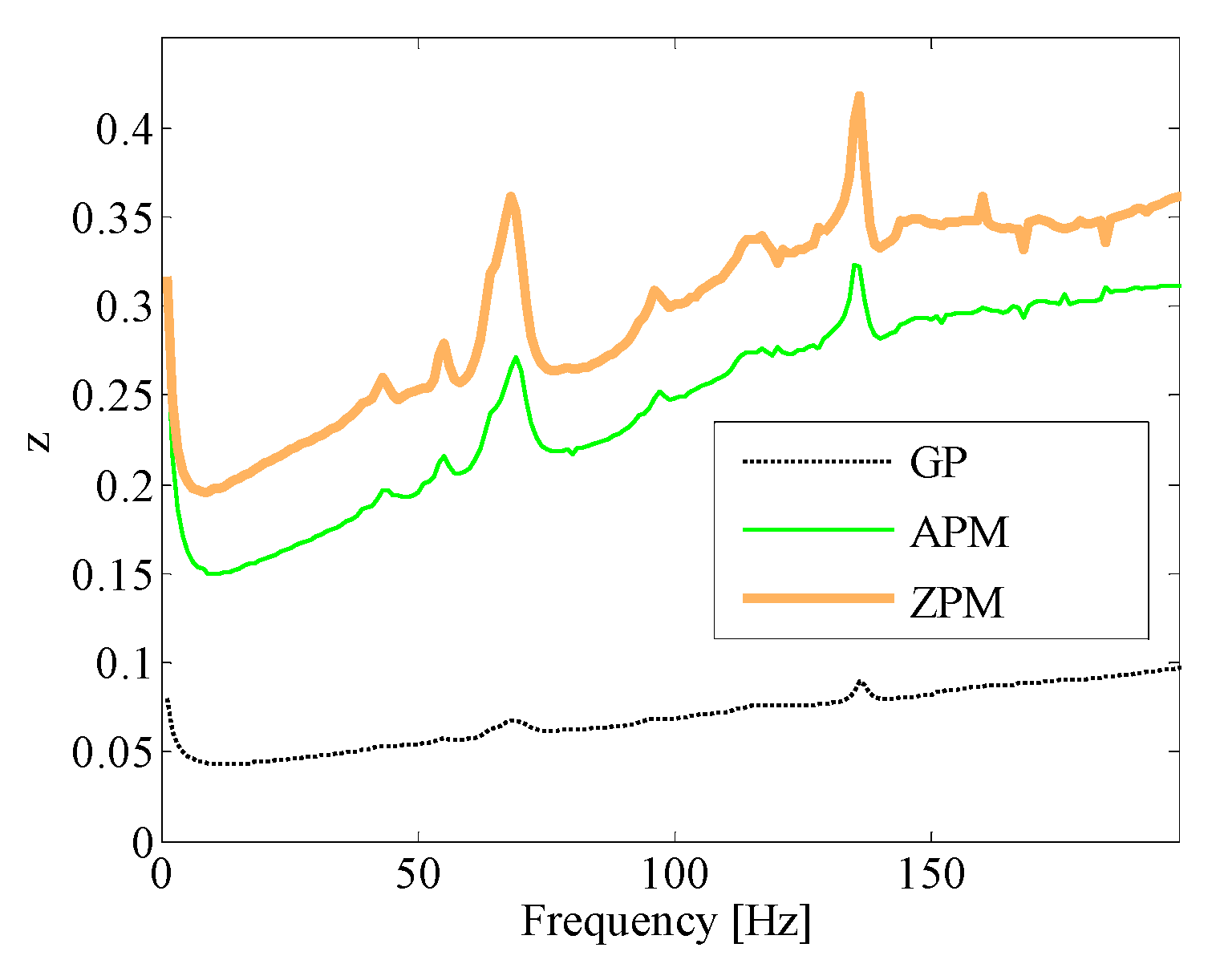
Evaluation of makes it possible to virtually estimate the damping behaviour of the beam under study, i.e., by using the previously defined function or by defining a new damping estimator , where .
5.4. Model Application Examples
Two different beam architectures are presented as examples, B1 and B2. Their data are reported in
Table 3 where
hi is the thickness of the
i-th beam layer. For both the examples
L = 1.1 m and
g = 0.08 m. The number of layers are
N = 3 (B1) and
N = 7 (B2). The constant parameters
,
,
,
take into account the beam distributed viscoelastic boundary conditions (clamped-free) and are applied at
. Constant parameters
and
are used to define uniformly distributed viscous actions (
) that model the system inherent damping.
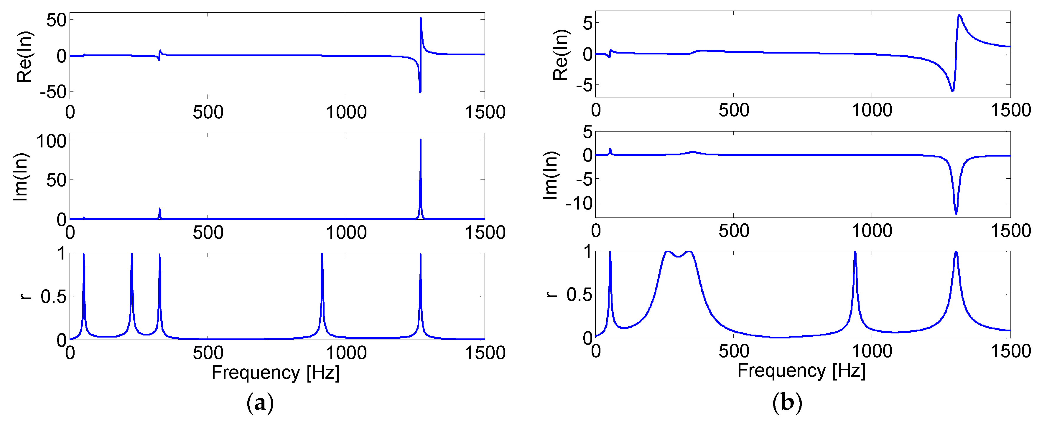
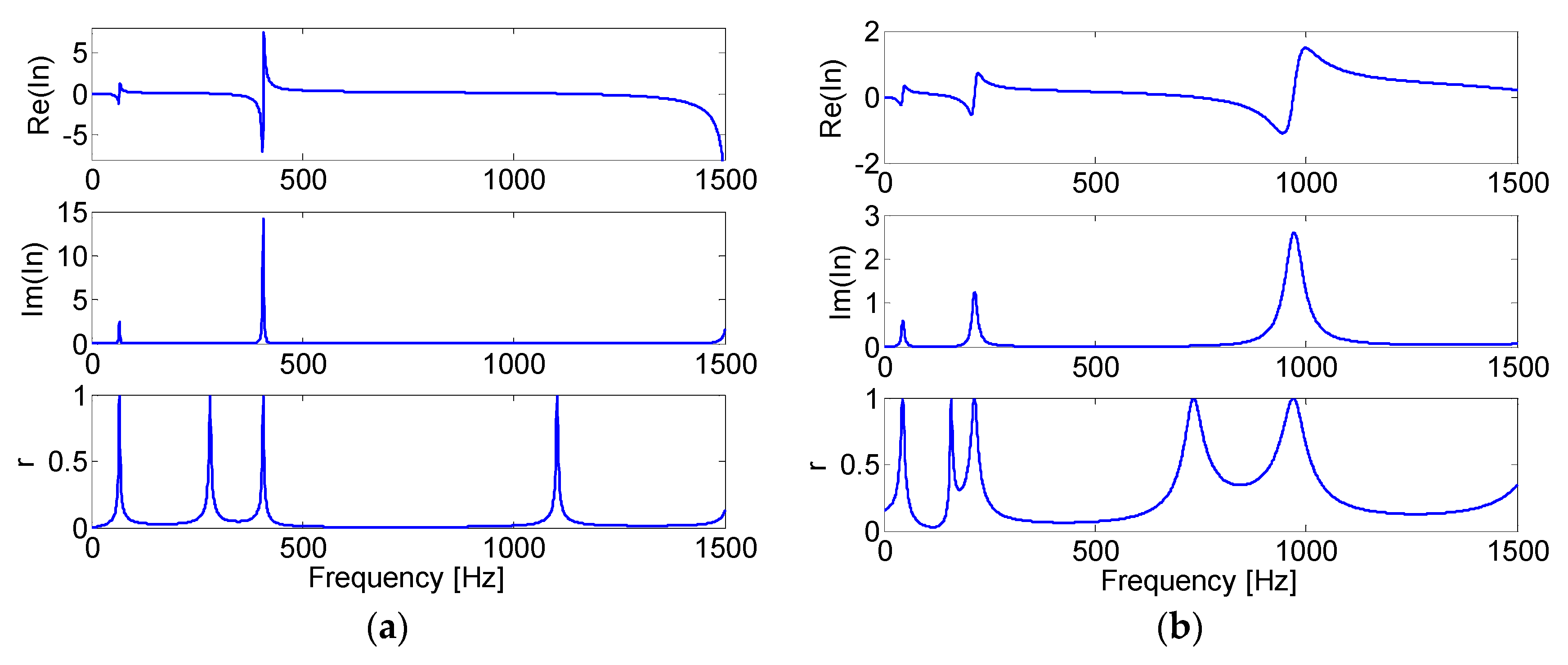
The effect of introducing hysteretic dissipative actions at the layer interfaces can be observed by comparing the results reported in
Figure 12 and
Figure 13. The real, the imaginary part of the inertance
frequency response function (FRF), calculated at
χw = 1 and
χq = 1, and the damping estimator
r(jw) are plotted.
Figure 12a and
Figure 13a show the results for beams B1
0 and B2
0 respectively, when no slipping occurs (
φi = 10
16 N/m
3,
ηi = 0,
),
Figure 12b and
Figure 13b show the results for beams B1 and B2 respectively, taking into account of interface slipping and hysteretic dissipation.
Table 4 reports B1, B1
0, B2, B2
0 natural frequencies and damping ratios. B1 and B2 damping ratios are estimated by means of the Single Degree of Freedom (SDOF) circle fit method [
45], while B1
0 and B2
0 damping ratios are normally obtained from within the solutions of a generalized eigenvalue problem [
45].
6. Conclusions
Eight different innovative composite solutions were experimentally investigated, and the results were compared; these findings were never before published. A significant increase of the damping behaviour is observed for all of these solutions with respect to the uncoated components, and also with respect to already known solutions, previously investigated by these authors and other researchers. The coating solution employing Al2O3 powder + matrix, made by screen printing and curing technology on Al alloy substrate, proved to be the most effective technology with respect to the aim of this work.
It can be outlined that the interface between substrate and coating heavily affects the effectiveness of the composite solution. Moreover, test results and comparison also outlined the influence of the substrate surface texture interface on the damped response. These results confirm the role of interface frictional actions in determining the composite damping behaviour. It should be outlined that the experimental estimate of the adhesion strength between coating and substrate can be evaluated by means of an adhesion test apparatus, and will be performed in future work.
An extended multi layered beam model was developed in order to design and optimize new, more effective coating solutions, engineered to maximize the damping contribution of frictional actions at the coating layer interfaces, or at the coating substrate interface. This model is based on high order multi-layer beam theories and takes into account of the contribution of interface frictional actions. The aim is to use the model as an experimental tool to identify the model parameters of the local dissipative actions acting at some interfaces between two different layers and as a design tool in order to explore new optimized coating solutions according to fixed engineering specifications. Some application examples of the model were presented. Nevertheless, experimental-numerical tools able to identify the complex elasto-hysteretic interface impedance must be developed in order to make this model suitable for engineering applications and will be presented in a future paper. Moreover, the application of this coating technology in real engineering applications, such as thin-walled components used in the automotive or automatic machine industry, should also be taken into account. Residual stresses at the interface between the coating layers and substrate may be taken into account in the multilayer beam model proposed in this work, since this contribution can be high and may be expected to play a major role in the adhesion behaviour of coated solutions when dealing with PVD based coating deposition technologies. It also appears that such extended beam models could also be used to experimentally identify this unknown residual stress field from measuring the deformed profile of a cantilever beam resulting from the application of a coated layer. Some analytical, numerical and experimental work is currently under development by our research team.


