1. Introduction
The development of ultra-low-power (ULP) and ultra-low-voltage (ULV) integrated circuits is driven by applications such as the Internet of Things (IoT) [
1,
2,
3,
4] and implanted biomedical devices [
5,
6,
7,
8]. The number of IoT devices connected to the internet for gathering and processing information is increasing at a faster and faster rate. The enormous number of connected devices and the fact that they are often battery powered or must scavenging energy from the environment make low power consumption a key feature in IoT devices [
1]. Therefore, the design of integrated circuits (ICs) for IoT applications is becoming more and more difficult due to the stringent constraints in terms of power dissipation, minimum supply voltage, and area footprint [
1,
2]. Due to the above constraints and the low intrinsic gain of nanometer MOS transistors, analog interfaces are, in many cases, the most challenging building blocks of ICs for IoT applications [
2,
3].
In the context of implanted biomedical applications, front-end amplifiers for neural recording systems often rely on AC coupling with cutoff frequencies below 1 Hz to eliminate the DC offset of the electrodes and to properly process the neural signals [
5,
6]. Such devices are usually designed for different frequency slots in the range from 1 Hz to 10 kHz. For example, in the case of epileptic seizure detection, band-pass filters in the range of 250 to 500 Hz are required to extract the signals of interest. Low-voltage operation, low power consumption, and a small silicon area are the main requirements of ICs for these systems [
7,
8].
ULP and ULV operational transconductance amplifiers (OTAs) are key components for both the IoT and implanted biomedical devices, and a huge number of OTAs have been presented in recent years [
9]. In [
10], Stockstad et al. presented a 0.9 V operational amplifier that, for the first time, exploited the bulk-driven technique to attain rail-to-rail input–output swing. Over the years, the research community has increasingly focused on reducing the supply voltage and power consumption at the expense of common-mode rejection ratio (CMRR) performance [
11,
12,
13,
14]. Several common-mode feedback (CMFB) approaches, which exploit triode-biased devices or current cancellation, have been proposed with the aim of minimizing the common-mode gain in fully differential OTAs, thus improving their CMRR performance [
15,
16,
17,
18,
19].
Multi-stage OTAs based on folded cascode or gain-boosting topologies and with supply voltages in the range from 0.6 to 0.9 V have been presented in the literature [
20,
21,
22,
23,
24]. However, when targeting supply voltages lower than 0.4 V, the adoption of the topologies and design strategies reported above is no longer possible, and pseudo-differential or inverter-based architectures are often used [
25,
26,
27,
28,
29,
30,
31,
32]. In fact, at these supply voltages, gate-driven amplifiers are not adequate for ensuring a rail-to-rail input common-mode range (ICMR). However, due to the lack of tail current generators, pseudo-differential and inverter-based circuits typically exhibit a not-well-defined bias point and a poor CMRR, and body bias strategies are less effective due to the limited available voltage swing on body terminals.
ULV circuits can employ floating gate devices [
33] or body-driven stages [
34,
35] to increase the input common-mode swing. Body-driven input stages are inherently rail-to-rail in ULV applications, and forward biasing of the NP junctions is not a concern when supply voltages are lower than about 0.6 V. Unlike gate-driven stages, however, they tend to have higher noise, lower bandwidth, and resistive input impedance. Despite these shortcomings, there is no alternative at supply voltages around 0.3 V if a large common-mode input signal swing is desired. Furthermore, the gate terminals of the input devices can be used for biasing, the biasing current of the amplifiers can be accurately set, and pseudo-differential architectures can even be exploited.
Additional interesting OTA architectures based on fully digital operation were recently proposed in [
36,
37], which showed the feasibility of full standard-cell-based analog amplifiers.
In addition to gain and robustness considerations, ULP and ULV topologies may have low bandwidth (because of sub-threshold biasing) and poor slew-rate performance (because of low biasing currents). Hence, it is important to assess the OTA performance in terms of bandwidth and slew rate for a given current or power consumption and capacitive load, which refer to the popular large-signal and small-signal Figures of Merit (FOMs).
In this paper, we present a novel OTA topology based on a body-driven input stage with a dual path to improve CMRR that exploits body-driven current mirror load for differential-to-single-ended conversion at the output. The proposed OTA has only one high-impedance node, and can therefore be compensated at the output stage, thus avoiding Miller compensation. The body-driven input stage ensures the rail-to-rail input common-mode range, whereas the coupling between the first and second stages and the gate-driven output stage ensure high open-loop gain and good slew-rate performance.
The paper is organized as follows:
Section 2 describes the proposed topology;
Section 3 analyzes the small-signal and large-signal circuit responses, including the CMRR;
Section 4 reports the design and simulation results, with emphasis on the process, supply voltage, and temperature (PVT) variations, as well as on stochastic mismatch variations; a comparison with the related literature to highlight the advantages of the proposed topology in terms of the FOMs is also presented in
Section 4. Finally, the conclusions are reported in
Section 5.
2. Proposed Topology
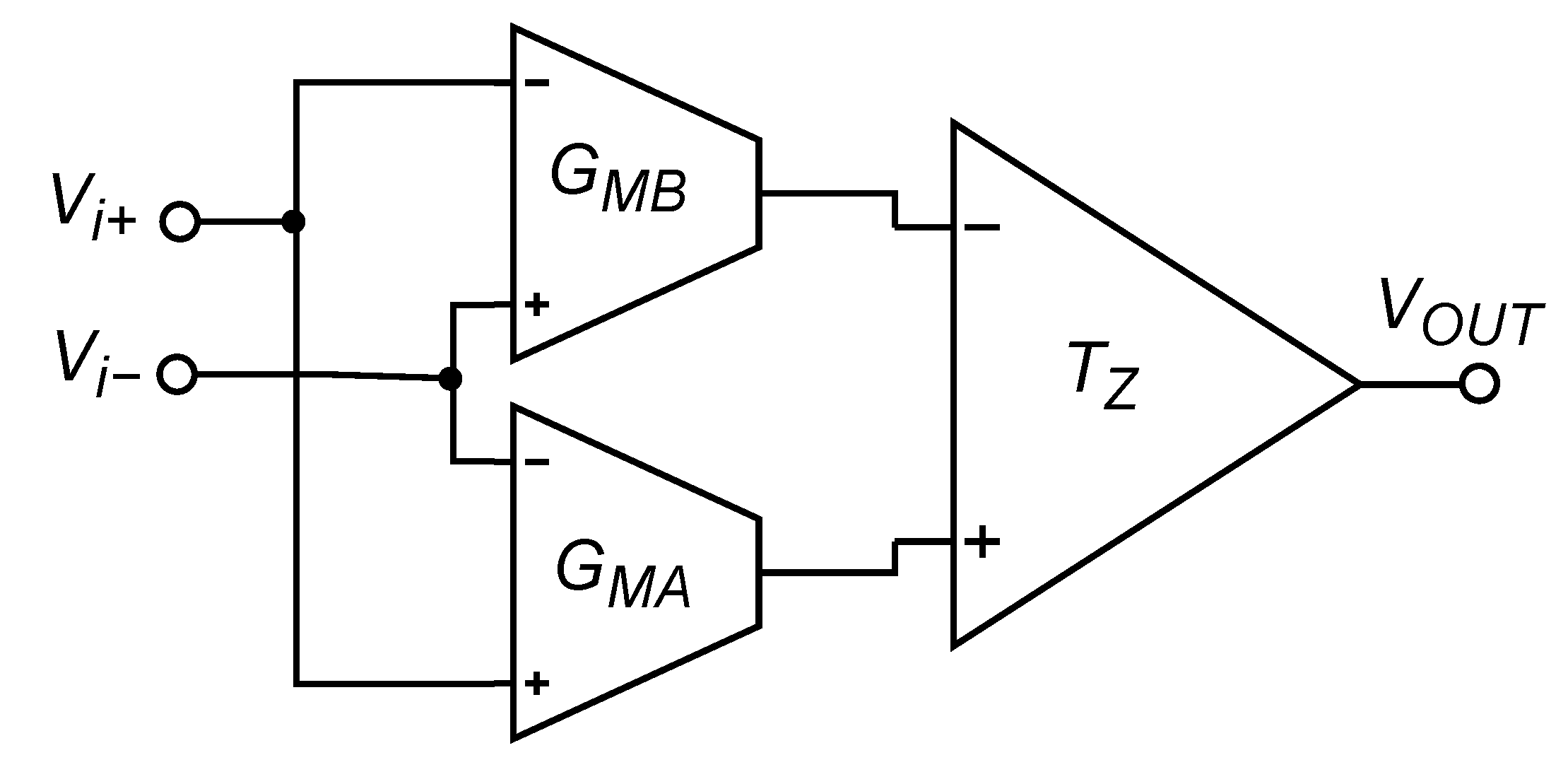
The block scheme of the proposed OTA is reported in
Figure 1, showing the usage of two matched transconductors
and
, whose output currents are sent to a transimpedance stage
, in which the common-mode currents are ideally cancelled, and the differential currents are summed to double the transconductance gain.
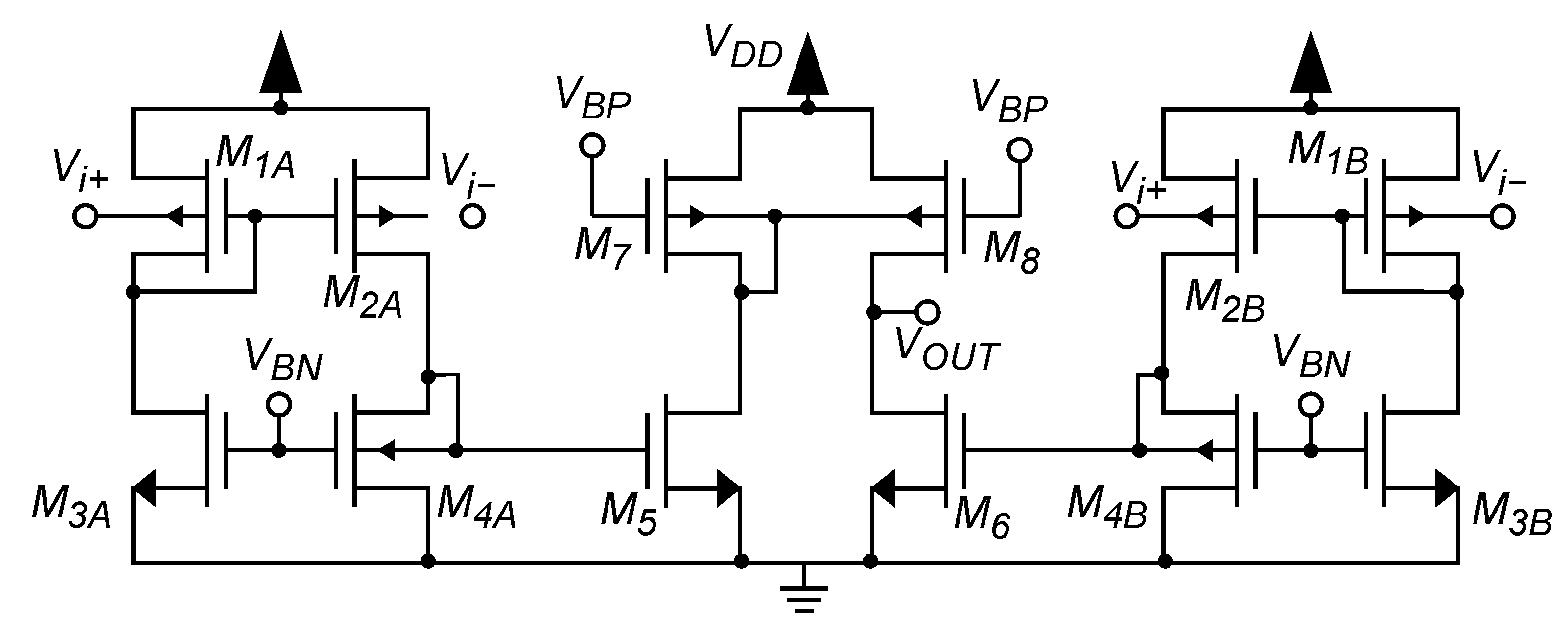
Figure 2 shows the detailed schematic of the OTA. Transistors
and
form the two input transconductance stages, which are shown in
Figure 1 as
and
. The second stage of the OTA is made up of transistors
, which implement the transimpedance stage
shown in
Figure 1.
To allow rail-to-rail input swing, a body-driven first stage is used. Due to the ULV supply, particular care was taken to identify a biasing strategy that was able to guarantee robustness with respect to the PVT and mismatch variations. In fact, since each transistor requires a minimum to properly operate, tail current generators are not an option, and the lack of tail current generators reduces common-mode rejection. Hence, the dual transconductance path in the input stage was exploited to guarantee high CMRR under the hypothesis of well-matched transconductances. Furthermore, since and comprise a current mirror and acts as a current source, a well-defined bias current is obtained. It has to be noted that the two transconductors and have to be designed symmetrically and must be well matched with each other in order to optimize common-mode cancellation. The second stage of the OTA exploits two body-diode NMOSs, so the input impedance is equal to . Transistors and act as current amplifiers. The gates of transistors and determine the biasing current of the second stage. The body-driven current mirror and provides differential-to-single-ended conversion and allows further rejection of the common-mode current component, since the common-mode current in and is the same. The output conductance of the stage provides voltage gain to the amplifier.
It has to be noted that the differential input stage is very similar to the one used in [
35,
38,
39]. However, in these works, the transconductors
and
are loaded by a conventional gate-driven current mirror, which performs the differential-to-single-ended conversion in the first stage. The first stage is then followed by one or two stages with Miller or Nested Miller compensation. In the proposed circuit, instead, the transconductors
and
are loaded by a differential body-diode load, and therefore, the input stage can be considered as a fully differential amplifier. The second stage of the proposed topology can be seen as a pseudo-differential pair loaded with a body-driven current mirror that performs the differential-to-single-ended conversion at the output, thus further increasing the CMRR and avoiding Miller compensation. The relatively high CMRR is obtained as a combination of two kinds of effects: the intrinsic CMRR of the simple differential pairs M1A-M3A and M1B-M3B, as explained in [
38], and trough symmetry and cancellation of currents due to the body-driven current mirror in the output stage.
5. Conclusions
In this paper, we proposed an ultra-low-voltage amplifier that operates at a supply voltage of 0.3 V and attains good Figures of Merit for both small-signal and large-signal behaviors. The amplifier exploits a pseudo-differential body-driven fully differential input stage and a gate-driven second stage, which performs differential-to-single-ended conversion. This provides a rail-to-rail input common-mode signal swing, large DC gain and CMRR, and good frequency performance. In particular, the amplifier does not present high-impedance internal nodes thanks to the body-diode active loads; thus, it does not require Miller compensation. The gate terminals are used for biasing, thus achieving robustness against PVT variations.
The comparison against the state of the art of ULV OTAs has shown how the proposed topology optimizes the trade-off between small-signal and large-signal performance, and achieves very good values for all of the considered FOMs.
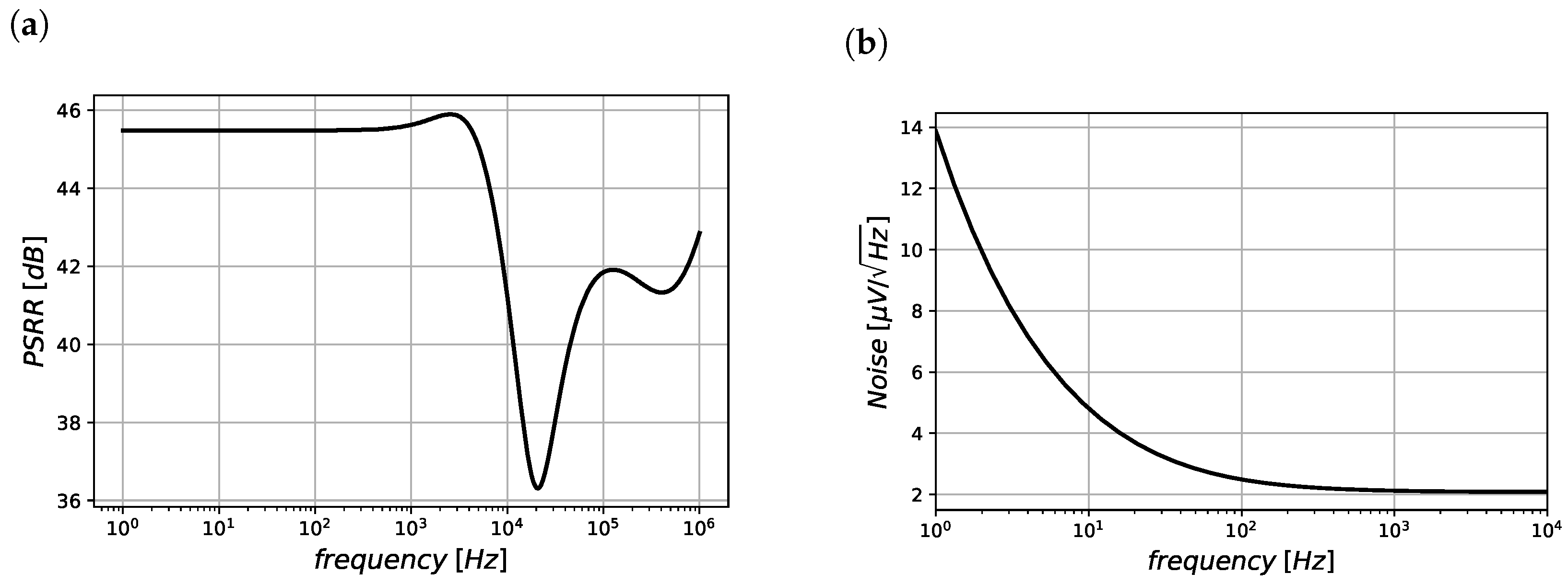
On the other hand, the proposed architecture presents limitations in terms of noise performance, exhibits an input impedance that is not purely capacitive, and shows a CMRR that is strongly dependent on mismatch variations. Another limitation is due to the body-driven current mirror load of the second stage, which causes an asymmetric slew rate. Nevertheless, these drawbacks are common to many ULV and ULP OTAs, in which a trade-off between many requirements has to be pursued.
It also has to be pointed out that, even if we presented results referring to a 130 nm CMOS process, the proposed topology can be implemented in even more advanced CMOS technology nodes, provided that the design guidelines outlined in the manuscript are properly followed. In particular, if a fully depleted silicon-on-insulator (FDSOI) CMOS process is available, the implementation of the proposed OTA (as well as of all body-driven OTAs) results in an input impedance similar to those of gate-driven circuits, and this is an interesting advantage over implementations based on conventional bulk CMOS processes, especially if switched applications are targeted.


 ,
, 


