1. Introduction
An IPT system can deliver power over relatively large air gaps via magnetic couplings, including a high-frequency inverter, compensation topology, coupling coils, and charging circuits. An IPT system has the excellent advantages of safety with galvanic isolation [
1], high reliability [
2], and being environmentally friendly [
3] compared with traditional conductive charging technology. Nowadays, the IPT system has been widely employed in powering electronic applications, such as low-power portable electronic devices, implantable medical instruments [
4], electric vehicle (EV) charging [
5], and autonomous underwater power supplies [
6]. Much research has been conducted by numerous organizations, such as the Massachusetts Institute of Technology (MIT), Auckland University, Korea Advanced Institute of Science and Technology (KAIST), and Oak Ridge National Laboratory (ORNL).
The misalignments between the primary and secondary magnetic couplers can cause the variation of self-inductances and mutual inductances, which may in practice lead to a reduction in power transfer, instability of the system, and increased power losses. Aside from that, the equivalent load varies during the battery charging process [
7]. Therefore, the goal of this paper is to design an IPT system with high misalignment tolerance and load-independent current output.
In order to improve the misalignment tolerance of the IPT system, some control schemes, such as increasing DC-DC conversion [
8,
9], phase shift control, and variable frequency control [
10,
11,
12,
13,
14,
15], have been proposed to modulate the output current or voltage. The additional DC-DC converter combines with MOSFET, the filter inductor and capacitor, and the driver circuit, which results in extra volume and cost and decreasing the system efficiency. The phase shift control and variable frequency control usually need a wireless communication device to collect the voltage and current signals of the secondary side to realize closed-loop control. However, wireless communications can be interrupted in highly magnetic conditions, which may result in instability of the IPT system. Moreover, phase shift control may not achieve ZVS under a wide range of loads, which increases the switching loss, and variable frequency control may result in bifurcation phenomena and decreasing the output power. Hence, in order to solve the above-mentioned defects, considerable efforts focus on proper magnetic coupler design [
16,
17,
18,
19,
20,
21], such as bipolar and double-D pads, tripolar pads, quadruple-D pads, and unsymmetrical pads, which can offer a relatively uniform magnetic distribution. For example, the quadruple-D pads are proposed in [
16] to be tolerant to lateral misalignment, which consists double quadrature coils at the primary and secondary sides. Tripolar pads are proposed in [
18] to improve the omnidirectional misalignment tolerance. However, these tripolar pads need to consist of three inverters at the primary side. That aside, unsymmetrical pads are presented in [
19] to minimize the cost of copper and the size of the coil structure, adopting the method of concentrated magnetic flux to achieve misalignment tolerance. As an alternative method, hybrid topologies combining two different topologies with opposite output trends are implemented to maintain a stable output under misalignment conditions. A hybrid topology combines with LCC-LCC and SS topologies [
20,
21] to realize relatively constant power output within 50%
Y-axis misalignment. In [
22], LCC-S and S-LCC topologies are employed to tolerate 50%
X-axis pad misalignment, where the primary sides are connected in parallel and the secondary sides are connected in series. Although the previous hybrid topologies are able to tolerate a pad’s special misalignment, as shown in
Figure 1, the working range of misalignment tolerance is still narrow. Therefore, better misalignment tolerance, particularly with
Z-axis tolerance for different EV class heights with a wider coupling variation range, is desired, which is identified as the research gap for this research.
This paper presents a new hybrid topology using DD2Q pads to achieve stable output power at a large vertical misalignment, and the main contributions of this article are summarized as follows:
- (1)
This article proposes a new hybrid IPT system with high misalignment tolerance. The hybrid system consists of a series hybrid topology and LCC-LCC topology. The series hybrid topology and LCC-LCC topology are connected in parallel at the primary side and secondary side. The proposed approach can improve the output power compared with the single compensation topology and reduce the switch voltage stress. Moreover, the proposed hybrid IPT system can achieve a near load-independent current output.
- (2)
DD2Q pads are used in the hybrid IPT system, which consist of a single-Q coil and double-DD coils. The size of the DD2Q pads is 280 mm × 280 mm, and the air gap is 100 mm. The double-DD coils are orthogonally placed, and the Q coil is placed in a centrally symmetric position, which can realize decoupling of the DD and Q coils on the same side of the primary and secondary sides. Therefore, the independent current output of the series hybrid topology and LCC-LCC topology can be achieved.
- (3)
A parameter optimization method based on DD2Q mutual inductances is proposed to realize a relatively constant output current with high misalignment tolerance, which is able to simplify the control complexity. By using the monotonic decreasing characteristic of the series hybrid topology and monotonic increasing characteristic of the LCC-LCC topology to realize the complementary output of the two topologies, the output current is ensured to be relatively stable.
Specifically, the mathematical model of the proposed hybrid topology is systematically analyzed in
Section 2. In
Section 3, the mutual inductance characteristics of the DD2Q pads and the parameter optimization are presented. The experimental results are provided in
Section 4 to verify the theoretical analysis. Finally, the conclusion is drawn in
Section 5.
2. Theoretical Analysis
The circuit of the proposed hybrid IPT system is shown in
Figure 2, which consists of a series hybrid topology and LCC-LCC topology. The high-frequency inverter combines with four MOSFETs (Q
1–Q
4). Inductor
L0 and capacitors
C0,
C1, and
C3 (
L7,
C2,
C4, and
C7) constitute the series hybrid topology, while inductor
L8 and capacitors
C5 and
C8 (
L9,
C6, and
C9) constitute the LCC-LCC compensation topology. The primary and secondary sides of the series hybrid topology and LCC-LCC topology are both connected in parallel, together forming the proposed hybrid topology. The main magnetic coupling between the coils is
M12,
M34, and
M56. The full-bridge rectifier comprises four diodes (D
1–D
4). Because the inductor
L0(
L7) and capacitor
C3(
C4) are connected in series in the proposed hybrid topology, and therefore they can be treated as a passive component, such as inductor
Le or capacitor
Ce, which can be expressed as [
16]
The full-bridge rectifier is adopted in the secondary side, and thus the input voltage
UAB, the input current
IAB, and the equivalent resistance
RAB of the rectifier can be expressed as [
8].
2.1. Analysis of the Series Hybrid Topology
The circuit of the series hybrid topology is shown in
Figure 3, where
Uout is a high-frequency inverter output voltage. In order to minimize the VA rating of the power inverter, the compensation networks are tuned to the same resonant angular frequency
ω. Thus, the resonant parameters should satisfy the following equations:
According to Kirchhoff’s voltage law, we can find
where
,
,
,
,
,
,
,
,
,
,
,
,
,
,
.
By designing proper coupling structures, which will be discussed in
Section 3, the effects of the cross couplings (
M13,
M14,
M23, and
M24) on the output can be ignored. Hence, by solving Equation (4), the currents are expressed by
According to Equation (5), the input equivalent impedance
Zin-series of the series hybrid system can be deduced to be
According to Equations (5) and (6), the series hybrid topology can achieve zero phase angle (ZPA). Aside from that, the output current
I3 is related to the inverter output voltage
Uout, resonant angular frequency
ω, inductors
L0 and
L7, and mutual inductances
M12 and
M34. In order to achieve symmetry between the primary and secondary circuits, inductors
L0 and
L7 are usually assumed to be the same. The main mutual inductances
M12 and
M34 are assumed to have the linear trend with the air gap, which will be discussed in
Section 3. Therefore, the output current of the series hybrid topology is shown in
Figure 4, where all the related parameter values will be listed in
Table 1. It is obvious that the output current
I3 shows a downward concave parabolic trend with the decrease in the mutual inductance. Although the series hybrid topology has a certain misalignment tolerance, the operating range is still narrow.
2.2. Analysis of the LCC-LCC Topology
Figure 5 shows the LCC-LCC equivalent circuit, where
Uout is also a high-frequency inverter output voltage. The compensation topology is tuned to the same resonant angular frequency
ω. Therefore, the resonant tanks should satisfy the following equations:
According to Kirchhoff’s voltage law, we find
where
,
,
,
,
,
,
.
By solving Equation (8), the currents are yielded as
According to Equation (9), the output voltage of the inverter is also in the same phase with the current, which aids in maintaining ZVS across the entire operating region and improving the output efficiency of the system. The output current
I7 is related to the inverter output voltage
Uout, resonant angular frequency
ω, inductors
L8 and
L9, and mutual inductance
M56. In this paper, inductors
L8 and
L9 are also assumed to be the same. Therefore, the output current
I7 is shown in
Figure 6, where all the related parameter values will be listed in
Table 1. It is clear that the output current
I7 shows a monotonous downward trend with the decrease in the mutual inductance.
Therefore, the series hybrid compensation network and the LCC-LCC compensation network can be connected in parallel at the transmitter and the receiver, which is conductive to achieving a relatively constant power output with large misalignment.
2.3. Analysis of the Proposed Hybrid Topology
According to Equations (5) and (9), the total output current of the inverter is expressed by
Then, the total input equivalent impedance of the proposed hybrid topology can be given by
From Equations (10) and (11), the total input impedance of the proposed hybrid topology is purely resistant, which aids to improving the overall transmission efficiency.
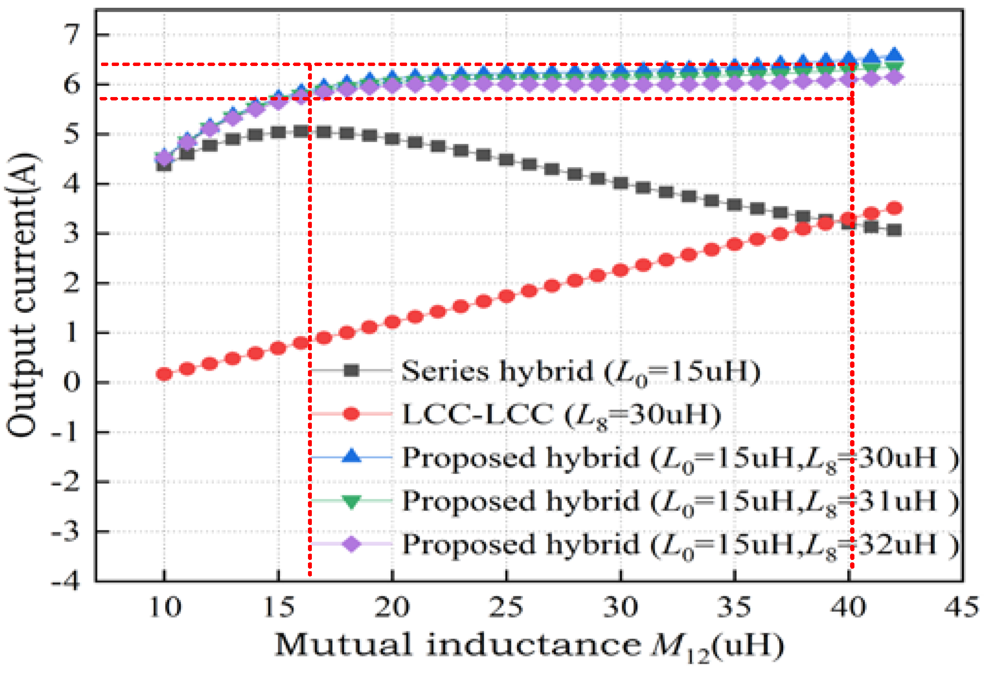
According to the characteristics of the parallel circuit, the total output current of the proposed hybrid topology can be expressed as
From Equation (12), the system can realize a load-independent current output. When misalignment occurs, the main mutual inductance M12, M34, and M56 will drop at the same time. By designing appropriate compensating inductors L0, L7, L8, and L9, the constant current output can be realized in a certain range of misalignment.
4. Experimental Verifications
In order to verify the analysis of the proposed method, a 650-W hybrid IPT system was designed and implemented as illustrated
Figure 10. The detailed parameters of the system are listed in
Table 1. The inverter of the system operated with a fixed frequency and duty cycle control to demonstrate the performance of a constant current output with high misalignment tolerance.
The output current of the load is drawn in
Figure 11, varying with a full load, half load, and quarter load under different
Z-axis transmission distances. Within a 80–150-mm
Z-axis transmission distance, the output current of the load was between 5.7 A and 6.3 A, which indicates that the output current variation was within 5% when the system worked in the full load and half load conditions. Aside from that, the output current of 4 Ω under the condition of a transmission distance between 110 mm and 130 mm was larger than 6.3 A, which was slightly over the limitation of 5%. Moreover, the output current climbed to the maximum at a 120-mm
Z-axis transmission distance. This clearly demonstrates that the proposed hybrid topology with the parameter optimization process had high misalignment tolerance.
The experimental waveforms of
Uout,
Iout,
UL, and
IL with
RL = 17 Ω, 8.5 Ω, and 4 Ω are shown in
Figure 12,
Figure 13 and
Figure 14 when the
Z-axis transmission distance was 80 mm, 120 mm, and 150 mm, respectively.
Uout and
Iout are the inverter output voltage and current when the input DC power is 70 V, respectively.
Figure 12 illustrates the system operating at full load with
RL = 17 Ω. It is clear that ZVS could be achieved between an 80-mm and 150-mm
Z-axis transmission distance, which could reduce the switching loss and improve the efficiency. Moreover, the output current was 5.84 A, 6.21 A, and 6.16 A, and the load output voltage was 99.30 V, 105.61 V, and 104.75 V, respectively. Hence, the fluctuation of the load current was within 5% when the variation of the
Z-axis transmission distance was within 70%.
Figure 13 shows the system works at half load with
RL = 8.5 Ω. The load output current was 5.92 A, 6.25 A, and 6.18 A, and the load output voltage was 50.30 V, 53.38 V, and 52.35 V, which illustrated the current fluctuation to be 1.33%, 4.17%, and 3.0%, respectively, meeting the design requirements. That aside, the output voltage and current of the inverter were almost in phase, which indicates that soft switching could be achieved and decrease the switching losses.
Figure 14 shows the system operating in a light load conditions when the load was 25% against the fill load with
RL = 4 Ω. The load output current was 5.96 A, 6.42 A, and 6.23 A, and the load output voltage was 23.84 V, 25.68 V, and 24.92 V, which illustrated the current fluctuation to be 0.66%, 7%, and 3.8%, respectively. It is clear that the output current may slightly exceed the limitation of 5% under light load conditions.
Figure 15 clearly illustrates that there is an opposite trend of the output current
I3 of series hybrid topology and the output current
I7 of the LCC-LCC topology when the
Z-axis transmission distance varied, and the RMS values of the output currents
I3 and
I7 had a slight deviation from the theoretical analysis in
Section 2 due to the influence of parasitic resistance and parameter drift on the resonant parameters. Aside from that, the total output current
IAB of the proposed hybrid topology could almost remain stable. Moreover, there was a small phase angle between the output current of the series hybrid topology and LCC-LCC topology because the resonant parameters in the series hybrid topology and LCC-LCC topology operated in a weak inductive state.
Figure 16 shows the output power and efficiency along the
Z-axis transmission distance.
Figure 16a illustrates that the output power was relatively gentle and consistent with the variation curve of the load output current. The maximum output power was 650 W when the
Z-axis transmission distance was 120 mm at full load with
RL = 17 Ω.
Figure 16b shows that the efficiency varied with the load and misalignment, and the maximum efficiency could reach 91% with a full load at an 80-mm
Z-axis transmission distance.
Some comparisons with traditional control schemes and existing hybrid topologies are listed in
Table 2, which are made in terms of control, number of inductors and capacitors, coupling pads, misalignment tolerance, cost, output characteristic, etc. Compared with the traditional control schemes in [
9,
11], the proposed IPT system can realize a constant current output and misalignment tolerance without additional DC-DC converters and phase shift control, which can simplify the complicated controls. The topologies in [
18,
21,
22] are named the “series hybrid topology”, while the topologies in [
20] are named the “parallel hybrid topology”. These mentioned hybrid topologies all use four coils to transfer power. Aside from that, the number of inductors, capacitors and coupling pads and the cost of the hybrid topologies are higher than the traditional topologies with closed-loop controls. Moreover, the proposed hybrid topology has a wider misalignment tolerance compared with the four-coil hybrid topologies in [
18] and [
20,
21,
22], even though this topology has slightly more components than the other topologies. Thus, the proposed hybrid topology is superior to the traditional control schemes and other hybrid topologies in terms of misalignment tolerance.
5. Conclusions
A hybrid wireless charging system using DD2Q pads has been presented to improve the misalignment tolerance. The new proposed system, combined with the series hybrid topology and LCC-LCC topology, was studied based on the full mathematical model in the context, where the DD2Q pads consisted of a single-Q coil and orthogonal DD coils. The new pad geometry is able to decouple the cross-mutual inductances so as to realize the independent output of the two topologies. Moreover, a parameter optimization design method on the basis of the characteristics of the DD2Q pads is presented to maintain a stable output current and provide high misalignment tolerance in the Z-axis direction. A 650-W hybrid IPT system has been designed and implemented to verify the analysis of the proposed method. The experimental results validate that the proposed hybrid topology can maintain a relatively constant output current at 6 A when the Z-axis misalignment varies from −20 to +50 mm, and the output current fluctuation is within 5% when the load varies from 100% full load to 25% light load. In comparison with the conventional hybrid topology, the new proposed system showed a significant improvement in Z-axis misalignment tolerance, even though this topology has slightly more components. Moreover, the maximum efficiency can reach 91% when the Z-axis transmission distance is 80 mm.
In future research, a thorough economic analysis of the proposed method will be adopted to minimize the system cost, which consists of the number of inductors, capacitors, and coupling coils. That aside, the coupling coil structure should be improved to have better X-, Y-, and Z- misalignment tolerance.


