Article

Design and Development of Shadow: A Cost-Effective Mobile Social Robot for Human-Following Applications

RoboLab, Robotics and Artificial Vision, University of Extremadura, 10003 Cáceres, Spain
*
Author to whom correspondence should be addressed.
Electronics 2024, 13(17), 3444; https://doi.org/10.3390/electronics13173444
Submission received: 29 June 2024 / Revised: 19 August 2024 / Accepted: 21 August 2024 / Published: 30 August 2024

Abstract

:
This study explores the development and implementation of Shadow, an advanced mobile social robot designed to meet specific functional requirements. Shadow is intended to serve both as a versatile tool and a human companion, assisting in various tasks across different environments. The construction emphasizes cost efficiency and high agility, utilizing 3D printing technology exclusively. The robot features omnidirectional kinematics and a flexible power electronics system, accommodating diverse energy needs with lithium batteries that ensure at least seven hours of autonomous operation. An integrated sensor array continuously monitors the power system, tracks tilt and acceleration, and facilitates self-diagnostic functions. Rapid prototyping allows for swift iteration, testing, and refinement to align with project goals. This paper provides a comprehensive blueprint for designing cost-effective, highly agile robots using advanced manufacturing techniques. Extensive testing, including stability and sensory skills evaluations, demonstrates Shadow’s adherence to its design objectives. Shadow has advanced from technology readiness level (TRL) 2 to TRL 7 within a year and is currently undergoing trials with advanced functionalities, offering significant insights into overcoming practical design challenges and optimizing robot functionality.

1. Introduction

The evolution of robotics has ushered in an era where robots are not only utilized for industrial automation but have also become integral to everyday human activities. A significant advancement is the development of social robots designed to interact with humans and assist in various tasks. Social robots are autonomous systems capable of communicating, interacting, and collaborating with people naturally and effectively. These technologies can potentially revolutionize the near future, enhancing assistance in healthcare, education, and customer service sectors [1,2]. In this context, we present Shadow, an innovative mobile social robot that embodies this trend by integrating low-cost prototyping and manufacturing techniques. Shadow is equipped with advanced sensors to improve human-assisted applications.
The demand for social robots seamlessly integrating into human environments is rapidly growing. Studies indicate that social robots can revolutionize human-robot interaction by providing companionship, enhancing productivity, and assisting in daily activities [3]. To achieve this, social robots must evolve rapidly to keep pace with technological advancements and meet user preferences and requirements. However, several factors, like scalability, limit robot designs’ adaptability and effective lifespan. Current challenges include integrating advanced sensors like 360° cameras and 3D LiDARs, and robust embedded GPUs for real-time processing of deep neural network models. Closed or restricted upgrade options in commercial robots can quickly lead to obsolescence.
This paper proposes the design of the Shadow social robot guided by the following research questions: (i) What design features enhance a social robot’s use and acceptability during human following in real environments? (ii) How can the robot’s design adapt to different environments and function autonomously for extended periods? (iii) What basic equipment (sensors) should a social robot be equipped with to follow a person in a real environment effectively? The Shadow robot aims to address crucial questions related to human-following capabilities. It aims to offer companionship and support during extensive work tasks in various settings. This paper seeks to create a cost-effective, agile, and adaptable social robot. We employ 3D printing technology to achieve these goals, directly supporting low-cost production and rapid iterations. This technology enables the efficient and economical advancement of social robot development, facilitating prototype creation and continuous improvement.
This article is organized as follows: Section 2 provides a background on the role of social robots like Shadow, discussing various research questions related to functionality and acceptance. Section 3 outlines the requirements considered during the design and development of the robot. Section 4 describes the body design of Shadow, covering the prototyping process, the development of the mobile base and suspension systems, and the power electronics system used in the robot. It also discusses the various sensors integrated into Shadow. Section 5 presents the experimental results obtained during testing. Finally, Section 6 concludes the paper with a summary of findings and future work directions.

2. Background

The use of social robots has significantly expanded over the past decade, finding applications in various real-world settings such as healthcare, education, and customer service [4]. In healthcare, social robots like Paro and Pepper provide companionship and support to patients, particularly the elderly and those with cognitive impairments [5,6]. In education, robots like NAO and Robovie enhance learning experiences and engage students in interactive activities [7,8]. In the customer service sector, robots such as Pepper and various hotel concierge robots assist customers and improve service efficiency [
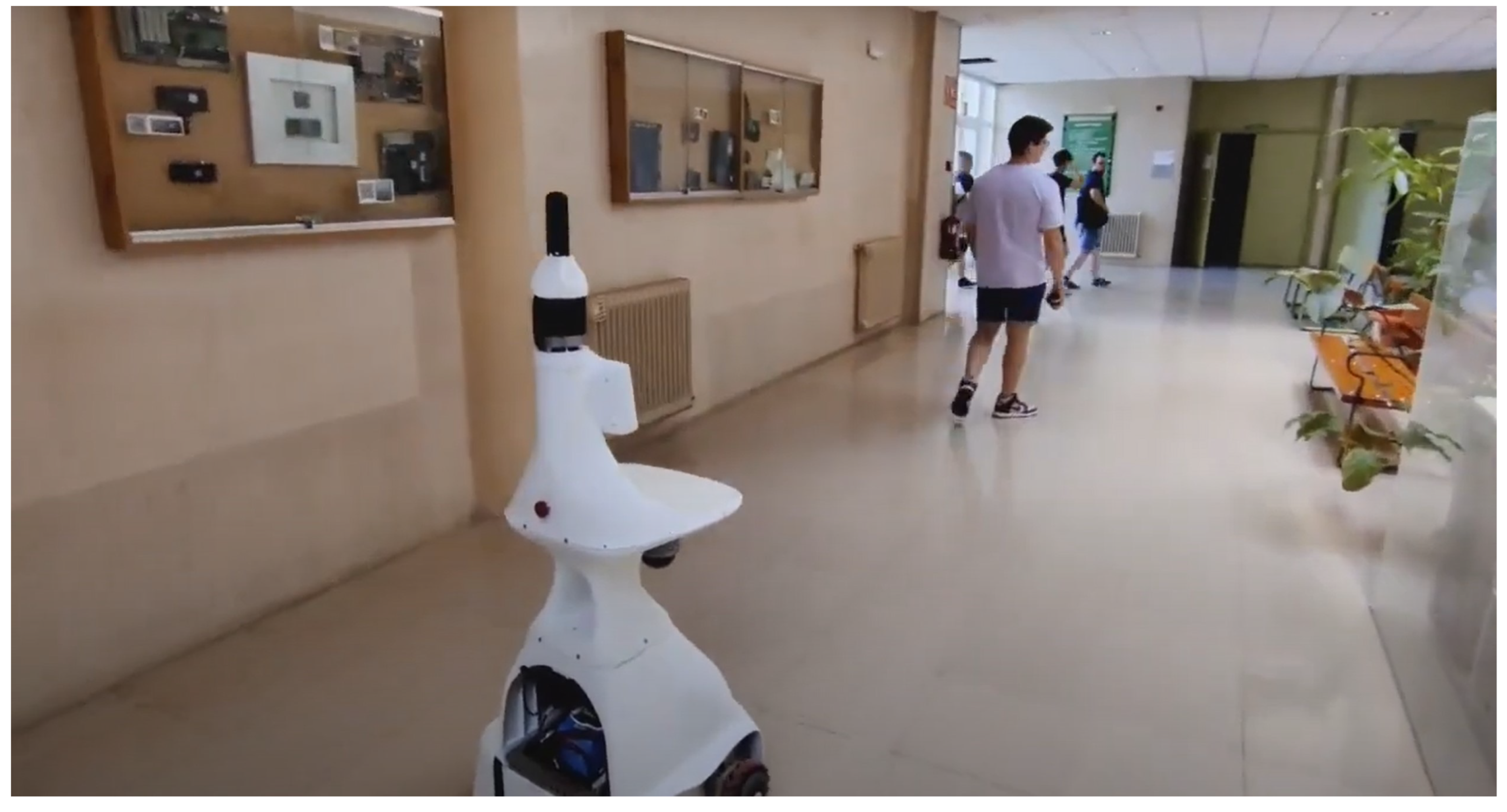
9]. These examples highlight the growing acceptance of social robots and their utility in enhancing human–robot interactions across diverse environments. The Shadow robot, designed explicitly for human-following tasks, is particularly useful in care environments and customer or visitor service settings.
For social robots to be effective, they must possess several key characteristics. Firstly, they need robust human detection and interaction capabilities to understand and respond to human cues accurately [10]. Secondly, they should exhibit adaptive behaviors to cater to user needs and preferences, ensuring a personalized interaction experience [2]. Additionally, they must be designed with safety and reliability, mainly when operating near humans, to prevent accidents and ensure user trust [
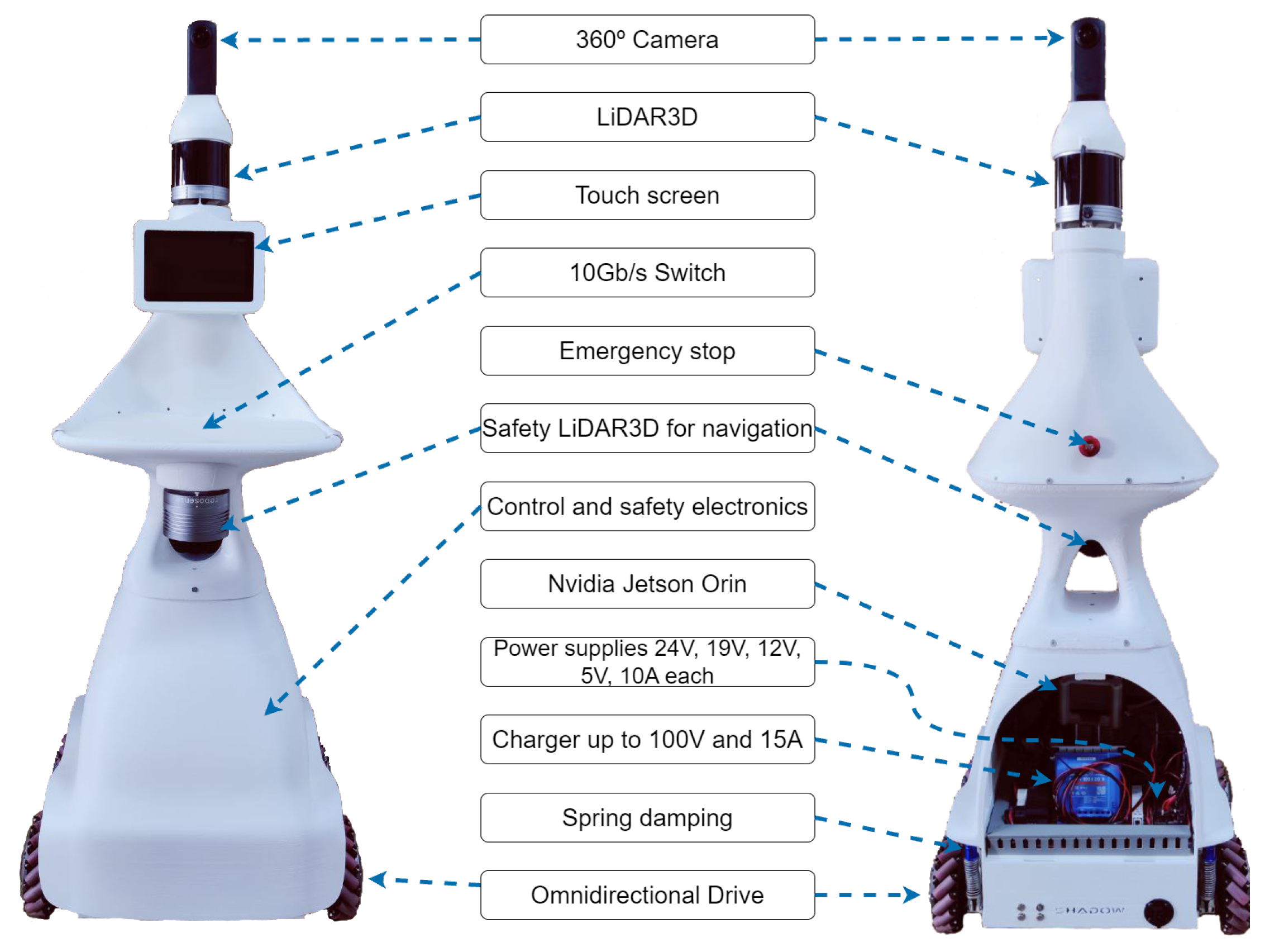
11]. These characteristics are essential for successfully integrating social robots into daily life, as they directly impact the robot’s ability to interact meaningfully and safely with humans. Our Shadow robot is equipped with various sensors, including 360o cameras and 3D LiDAR, along with a Jetson Orin, which enables the execution of specific algorithms for human detection, the calculation of safe and socially accepted routes, and interaction with humans in the environment.
The design of robots involves several critical considerations to ensure functionality and adaptability across various applications. Robot design has been revolutionized by 3D printing technology, allowing for rapid prototyping and customization of complex structures at a reduced cost [12,13,14]. Modular design approaches enable the creation of flexible systems that can be easily updated and expanded with new capabilities as needed [15,16]. Furthermore, incorporating advanced sensors is crucial for enhancing the robot’s perception and interaction capabilities, allowing it to operate effectively in dynamic environments [17,18]. Shadow leverages rapid prototyping through 3D printing, with tests and validations at each design stage. Additionally, Shadow is designed modularly to allow easy access to each component for replacement, upgrade, or repair. The arrangement of the sensors has also been carefully considered in the final system design.

Robot Comparison

As part of the design process of Shadow, we analyzed and compared several well-known commercial robots available for purchase and some custom-made robots built in research labs [4]. The comparison shown in the Table 1 considers only the functionalities offered by these units and advertised by the manufacturers.
One of the key aspects of Shadow’s design is its omnidirectional movement capability, which allows it to navigate in all directions with great agility. This feature is essential for maneuvering in complex and narrow environments. In contrast, most of the other compared robots, such as Morphia [19], WaPOCHI [21], Dinerbot T5 [22], Bellabot [23], Amy Waitress [24], Hobbit [25,26], and Giraff [27], lack this capability and rely on more traditional movements. TIAGo [20,28,29] has similar capabilities but they depend on the specific model or conditions.
All the robots analyzed, including Shadow, Morphia, TIAGo, WaPOCHI, Dinerbot T5, Bellabot, Amy Waitress, Hobbit and Giraff, feature autonomous navigation. This functionality enables robots to move independently within a defined environment, using sensors and algorithms to avoid obstacles and follow predefined routes. Autonomous navigation is critical for ensuring that robots can operate without constant human supervision, making them more efficient and practical for various applications.
Shadow, along with Morphia, TIAGo, WaPOCHI, Hobbit, and Giraff, includes the ability to detect people, which is essential for social interactions and human-assisted tasks. The capability to detect people allows these robots to interact meaningfully with their environment and the humans within it. However, Dinerbot T5, Bellabot, and Amy Waitress do not offer this functionality, potentially limiting their usefulness in applications where human interaction is crucial. The absence of this feature in some robots restricts their potential in settings where recognizing and responding to human presence is important.
Object manipulation is an advanced feature that allows robots to interact with their environment physically. Hobbit excels in this area, providing significant capabilities for handling objects. Shadow and TIAGo have limited object manipulation capabilities that depend on the model or conditions. On the other hand, Morphia, WaPOCHI, Dinerbot T5, Bellabot, Amy Waitress, and Giraff lack this capability, restricting their functionality to tasks that do not require direct physical manipulation. The ability to manipulate objects is precious in industrial and service applications where handling and moving items are necessary.
Video calling is a valuable feature for remote communication and telepresence. Although Shadow does not currently include this capability, it is designed to support it in the future, as it is equipped with the necessary components, such as a camera, microphone, and screen. In contrast, robots like Morphia, TIAGo, Hobbit, and Giraff already offer video-calling functionality, making them suitable for remote assistance and communication with distant users. However, WaPOCHI, Dinerbot T5, Bellabot, and Amy Waitress lack this feature, which may limit their effectiveness in scenarios requiring remote interaction. Incorporating video-calling capabilities would enhance the versatility of these robots, making them more effective in environments where visual and audio communication is crucial.
All the compared robots, including Shadow, have transportation capabilities. This feature allows robots to carry objects from one place to another within a defined environment, which is fundamental for logistics, services, and customer care applications. Efficient transportation of items is necessary in various settings, and the ability to perform this task makes these robots highly valuable for tasks involving movement and delivery of goods.
The ability to track and follow a specific person is an essential feature for assistive and social robots. Shadow, Morphia, TIAGo, WaPOCHI, Hobbit, and Giraff include this functionality, which is critical for applications where the robot needs to maintain proximity to a human user. Dinerbot T5, Bellabot, and Amy Waitress lack this capability, limiting their use in applications where human tracking is essential. Tracking capabilities ensure that robots can provide continuous assistance and support by staying close to the user.
Expandability is another important aspect of robot design. Shadow is designed to be expandable, allowing for the addition of new components and upgrades. TIAGo offers limited expandability, depending on the model, while Giraff has some expandable capabilities. Morphia, WaPOCHI, Dinerbot T5, Bellabot, Amy Waitress, and Hobbit are not expandable, which may limit their ability to adapt to new technologies and future needs. Expandability ensures that robots can be updated and improved, extending their usefulness and relevance.
Lastly, a low-cost focus is a significant consideration for making robots accessible for various applications. Shadow and several other robots, such as Morphia, Bellabot, Amy Waitress, Hobbit, and Giraff, are designed with a low-cost focus, making them accessible for various applications. TIAGo and other more advanced models do not emphasize cost reduction, which may make them less accessible for some users or applications where budget is a primary concern. The focus on cost efficiency allows for broader adoption and deployment of robotic technologies in different fields.
For a more extensive but similar comparison, see [30]. The table shows significant similarities in many of the compared functionalities. However, the day-to-day use of robots in research labs involves more subtle aspects that condition their long-term availability, such as adding more powerful computers, connectivity, software updates, part replacement, adaptation to new sensors, warranty, etc.
Shadow addresses the deficiencies found in many commercial robots, such as TIAGo, WaPOCHI, and Dinerbot T5. These robots often come with closed software and operating systems customized by the manufacturer, making upgrades to sensors, hardware, and processing components difficult. They also suffer from challenging maintenance procedures and high costs, with no option for users to create or customize the robot to their specific needs, and sometimes even require a subscription for the use of different functions. Shadow, on the other hand, provides solutions to these problems by offering an open platform that allows for easy customization and upgrades, making it more adaptable and user-friendly at a lower cost. This is particularly valuable to researchers, educators, and developers.

3. Requirements

As mentioned above, Shadow is a low-cost social robot that requires great agility and responsiveness in its movements. It must be able to adapt to a dynamic environment with people and interact with them. In addition to being physically stable to operate reliably and continuously, with a minimum autonomy of 7 h, the design of the robot must be human-friendly and safe, it needs to have the necessary sensors to locate and recognize people and must reach a minimum speed of 3 km/h to follow a walking person.
Another important requirement is the size, which must be large enough to accommodate all the necessary technology and, at the same time, small enough to move freely in the environment. The maximum size allowed is 625 mm wide and 2030 mm high, as these are the minimum door dimensions according to [31]
Completing the section, the robot must be easy to upgrade, maintain, and manufacture and have the necessary technologies to perform its task in real time.

4. Shadow Robot

Shadow is a robot with a design that ensures cost effectiveness without compromising functionality. This balance is achieved through 3D printing, enabling rapid prototyping and customization, allowing the creation of complex structures at a reduced cost. As highlighted by [13], additive manufacturing technologies like 3D printing transform the robot design and production landscape, making developing sophisticated robots on a budget feasible. Another crucial aspect is the acceptability of Shadow’s movement within its environment, addressing the growing demand for lighter, more agile designs akin to biological movement [32]. The recent availability of high-powered wheel-motor units and custom-configured lithium batteries has enabled more compact, lightweight, and efficient mobile bases. Additionally, the design includes sensors for high-level behaviors like people detection and tracking in complex environments, underscoring their significance in advancing robotic capabilities [33].
Therefore, constructing our social robot (Figure 1) addresses these challenges. Shadow leverages a quick prototyping cycle enabled by large-format 3D printers (Creality CR SO 60 PRO, Creality Store, Shenzhen, China) and a modular power electronics design, identifying and resolving several design challenges to ensure the final product meets its objectives. The iterative nature of rapid prototyping refines robot designs, enhancing functionality and reliability [13,34].
Shadow is equipped with omnidirectional kinematics (Mecanum wheels and Drivers, UU Motor Technology Company Ltd., Chanzhou, China), allowing it to navigate complex environments smoothly. A versatile power electronics system complements this design feature and can adapt to varying energy requirements. Lithium batteries were chosen for their high energy density and reliability, ensuring a minimum of seven hours of autonomous operation. Additionally, an array of sensors continuously monitors the power system’s status, tilt, and acceleration, supporting a self-diagnostic function that enhances the robot’s reliability and performance. Shadow integrates LiDAR (Helios and BPearl, RoboSense Technology Co., Ltd. Shenzhen, China) and 360° camera (Theta Z1, Ricoh Company, Ltd., Tokio, Japan) for complete environmental perception, supported by a high-capacity NVIDIA Jetson Orin (Jetson Orin, Nvidia Corporation, Santa Clara, California) for executing specific algorithms. The robot also features a touch screen for future interactions and a tray on the front for use during tracking tasks.

4.1. Prototyping

Agile methodologies, such as rapid prototyping, have been utilized in the manufacturing of Shadow. This prototyping phase is a critical step in developing any advanced robotic system. Rapid prototyping using 3D printing technology was employed for the Shadow robot to achieve cost efficiency and design flexibility. This iterative design process involved multiple steps, from initial concept models to functional prototypes. Emphasis was placed on using large-format 3D printers, which allowed for the creation of complex structures and components with high precision. The advantages of this approach include the ability to quickly test and refine the design, illustrating the effectiveness of rapid prototyping in modern robotic engineering.
We iterated over a series of prototypes to meet Shadow’s specific design requirements. This process allowed us to detect inappropriate design decisions that led to undesirable situations, which only became apparent once the prototype was built and tested. Two significant sources of error identified were the configuration of the volume inside the plastic casing and the vibrations transmitted to the tray. By addressing these issues, we were able to improve the overall design and functionality of the robot.
The 3D printing technology revolutionized our approach to robot design, enabling rapid prototyping and customization of complex structures at a reduced cost [12,13,14]. This method provided the flexibility needed to iterate on designs quickly and efficiently. Each prototype underwent rigorous testing and validation, ensuring design flaws were identified and corrected early in development. The benefits of this approach are evident in the precision and reliability of the final product.
Furthermore, the iterative prototyping process enabled us to refine the robot’s design continuously. Large-format 3D printers allowed us to create detailed and accurate models, facilitating swift adjustments and enhancements. This approach improved the design and ensured that Shadow met all the specified requirements, including robustness, flexibility, and cost effectiveness.
The result of the first year of work on this robot is shown in Figure 2 as a series of prototypes. Each iteration brought us closer to a final design that effectively balances functionality, adaptability, and user requirements.

4.2. Body Design

The body of Shadow was conceived as one sizable printable piece that serves as both the supporting structure and the functional shape for external (human-robot interaction; HRI) and internal (electronics and cables guiding) requirements. However, the size limitation of our 3D printer (500 × 500 × 600 mm) forced us to divide the body into three pieces and a small connecting element. This segmentation posed challenges in ensuring the structural integrity and alignment of the components, which were addressed through precise design and robust connectors.
The three main body sections of the robot were meticulously designed to interlock seamlessly, forming a robust and cohesive structure. Each section was printed separately, enabling precise attention to be given to the specific requirements of each part, such as sensor placement, accessibility to electronic components, and the routing of cables. A small connecting element played a critical role in maintaining the alignment and stability of the entire assembly, thereby ensuring that the structural and functional integrity of the robot remained uncompromised.
Additionally, this modular design allows for scalability in the construction of the robot. This means that certain elements, like the lower section housing the electronics and wheels, can remain unchanged, while other parts can be modified or replaced to introduce new functionalities or features. For instance, modifications might include the addition, removal, or expansion of sensors and actuators, enhancing the robot’s adaptability to different tasks or environments.

4.3. Mobile Base

Shadow has been designed with omnidirectional kinematics to achieve high mobility using four Mecanum wheels in a rectangular configuration. This design choice allows the robot to move in any direction without changing its orientation, providing a significant advantage in navigating complex environments. Additionally, this type of natural movement is more readily accepted by people [32], aligning with the robot’s primary objective of following a person seamlessly and intuitively.
Figure 3 illustrates the Mecanum wheels and the coordinate systems used in the omnidirectional base. The Mecanum wheel, shown in Figure 3a, allows the robot to move in any direction by varying the speed and direction of each wheel. Each wheel has rollers set at a 45 degree angle to the wheel’s plane, allowing forward, backward, and lateral motion to be combined into a single movement. Figure 3b details the coordinate systems that describe the robot’s omnidirectional movement, showing the wheels’ positions and the rollers’ orientation.
The inverse kinematics equations required to control the robot were derived following the methodologies, as outlined in [35,36]. These equations are crucial for converting the desired movements of the robot into the specific rotational speeds for each wheel. As shown in Figure 3a, at the center of the wheel, the linear velocity v = ( v x , v y ) is the sum of the velocity components along the driving direction and the sliding direction:
v x v y = v d r i v e 0 1 + v s l i d e c o s γ s i n γ
where γ denotes the angle at which free sliding occurs, allowed by the passive rollers on the wheel’s circumference; v d r i v e is the driving speed; and v s l i d e is the sliding speed. Solving Equation (1) for v d r i v e and v s l i d e we obtain
v d r i v e = v y v x tan γ v s l i d e = v x cos γ
When the robot is moving with velocity ν = ω z v x v y , each wheel u i has an angular speed given by
u i = 1 r i t a n γ i r i x i 0 1 y i 1 0 ω z v x v y
with x i , y i being the coordinates of wheel u i with respect to the center of the robot, γ i is the angles of each roller, and r i is the radius of each wheel. From right to left, the first transformation expresses the linear velocity at the wheel in the robot’s center b. The second transformation calculates the driving angular velocity using Equation (2).
To obtain the final inverse kinematics equation, the position coordinates of each wheel and the angle of its roller, ± 45 , are substituted into Equation (3). As an example, for wheel u 1 with γ = π 4 ,
u 1 = 1 r i 1 r i w 0 1 l 1 0 ω z v x v y = w - l 1 1 1 r 1 ω z v x v y
Each u i vector is stacked as rows in a matrix to obtain Equation (5). This equation links the desired velocity of the robot’s center, v x , v y , ω z , to the linear speed of the wheels, u i . The geometric parameters w and l denote the semi-distance between wheels and the semi-distance between axes, respectively.
u 1 u 2 u 3 u 4 = 1 r w l 1 1 w + l 1 1 w + l 1 1 l w 1 1 ω z v x v y
By setting v z and v y to zero, the equation sends all the wheels’ speeds to the same value, making the robot move forward. For lateral speed v y 0 , wheels in the same diagonal receive the same sign in the speed magnitude. For rotation, wheels on the same side receive the same sign and a magnitude scaled by the geometric parameters.
This omnidirectional configuration has been translated to the real robot using four Mecanum motor wheels. Each wheel includes a 150 W hub motor controlled by one of the two 2-axis drivers provided by the same manufacturer.

4.4. Materials

In fused deposition modeling (FDM) printing, a variety of materials are available, each offering unique characteristics such as resistance to external elements, toughness, flexibility, and hardness. The materials selected for testing include PLA (polylactic acid), ABS (acrylonitrile butadiene styrene), TPU (thermoplastic polyurethane) HARDNESS+, and PC (polycarbonate), with all plastics manufactured by Smart Materials 3D.
  • PLA: is a cost-effective, easy-to-print, and cheap material. However, it has a low thermal resistance and can become malleable at temperatures of around 65 °C.
  • ABS: offers better mechanical and thermal performance compared to PLA. It is more challenging to print, particularly for long-duration prints, due to warping, where the first layer may lift off the print bed. Despite this, ABS is tougher and more heat-resistant than PLA.
  • TPU HARDNESS+: this material is more impact-resistant than both PLA and ABS and offers good flexibility. It is also relatively easy to print, though it comes at a higher cost. TPU’s properties make it suitable for applications requiring durable parts.
  • PC: polycarbonate is known for its exceptional rigidity and strength. However, it is brittle and challenging to print with, often resulting in imperfections and inaccuracies. These defects can create stress concentration points, leading to potential fractures under load.
Initially, PLA was chosen for constructing the robot’s body due to its ease of printing, low cost, and adequate structural properties.
In Figure 4, two types of simulations are presented: static displacement analysis and static strain analysis. These tests were conducted to evaluate the robot’s ability to support its own weight, as well as additional loads. The first test involved applying a gravity force on the Shadow, the second applied a distributed force of 40 kgf on the tray, while the third applied a distributed force of 10 kgf. The results indicate that the structure of the robot, constructed from PLA, can support these weights without exhibiting significant or hazardous deformation.
However, the high torque generated by the wheels imposed significant stress on the chassis–wheel connections, leading to issues such as wheel axle penetration when using PLA and ABS. Additionally, PC was deemed unsuitable due to its printing difficulties. After extensive testing under prolonged operational conditions, TPU was selected for its superior durability and flexibility, which are crucial for maintaining structural integrity under stress, as shown in Figure 5b.

4.5. Suspension System

In our first prototype, the wheels were directly attached to the chassis. This design led to premature wear of the plastic part of the chassis holding the wheel’s axis. To mitigate this, we introduced an intermediate element made of a more resistant material, as shown in Figure 5a. Additionally, the generation and transmission of vibrations caused by the fixed attachment were problematic, highlighting the need for a more effective solution. Consequently, the design of Shadow’s suspension system became crucial for ensuring stability and smooth operation across various conditions.
To address these issues, we implemented a robust suspension system designed to manage weight distribution and absorb shocks, enhancing the robot’s durability and improving its interaction with the environment. This system allows for more precise and reliable human-following capabilities by minimizing the impact of uneven terrain.
During testing of the initial prototypes in real-world conditions, we encountered significant issues related to vibration. These vibrations were transmitted to the tray and the head, where the camera was mounted, rendering the tray unsuitable for carrying items such as medicines, bottles, or other tall objects. We identified three main causes of these problems: (i) misalignment of the Mecanum wheels; (ii) instability in the four-wheel configuration, often causing one wheel to lose contact with the ground; and (iii) the rigid connection of the motor wheels to the body. We resolved these issues by decoupling the wheels from the chassis through a micro-adjustable suspension system.
Figure 6a shows the initial design with the wheel directly attached to the chassis. The final design was engineered to support the robot’s weight while maintaining flexibility and responsiveness. In addition to decoupling the wheels from the chassis, shock absorbers and springs that could handle the dynamic loads encountered during operation were integrated. The placement and configuration of these components were optimized to ensure even weight distribution and to minimize vibrations that could affect the robot’s sensors and electronics. Our design is shown in Figure 6b and the implementation in Figure 6c.
This suspension system plays a vital role in managing the robot’s stability and performance, reducing the impact of vibrations and ensuring more reliable operation in various scenarios; see Section 5.1.
However, a static unit deformation analysis and static displacement analysis were performed on this damping system using different materials, including PLA, ABS, and TPU HARDNESS+. The analysis involved fixing the joint to the chassis and applying a vertical force of 60 kgf on the wheel axle, along with a torque force of 10 Nm. The motor’s maximum load capacity is 50 kgf, with a peak torque of 7 Nm, as shown in Figure 7.
The results indicate that the designed part can withstand these forces. However, TPU HARDNESS+ exhibits more deformation compared to PLA and ABS, primarily due to its greater flexibility. Despite this deformation, TPU HARDNESS+ remains harder and more durable under these conditions, as demonstrated in Figure 5b.

4.6. Power Electronics

The power electronics that drive Shadow have been designed to overcome the typical limitations of commercial robots, which often feature closed or poorly documented systems. Ensuring a robot’s longevity and adaptability requires an infrastructure that allows for the integration of new sensors and computing resources. These additional elements draw energy at various voltages, which the robot’s battery system must provide, and these requirements may not have been anticipated in the initial design.
We developed an extractable power electronics tray that offers multiple power buses to address this challenge. This tray can be easily resized by replacing the power supplies, ensuring flexibility and scalability. This modularity is crucial for extending Shadow’s operational life by accommodating technological advancements and changing mission requirements.
The primary goal of this design is to provide a robust and versatile power system that can support a wide range of devices. The tray includes several power buses with different voltage and current capabilities, as outlined in Table 2. This comprehensive distribution system ensures that all components, from high-power motors to delicate sensors, receive the appropriate power.
Figure 8 shows a detailed layout of Shadow’s power system. On the left side, the 1 kWh lithium battery occupies the lowest position in the chassis. This placement helps maintain a low center of gravity, improving the robot’s stability. Above the battery, the control buttons and charging socket are indicated, facilitating user interaction and recharging operations. A detailed view of the power electronics tray is provided on the right side of Figure 8. The tray includes various power supplies delivering voltages of 48 V, 24 V, 19 V, 12 V, and 5 V, each capable of supplying different amperages as needed. This configuration currently powers the four 150 W wheel motors, an NVIDIA Orin unit, two 3D LiDARs, a 360° RGB camera, and other smaller sensors and devices. The tray also houses the motor controllers and fuses, ensuring safe and reliable operation. The distribution terminals are marked, showing how power is routed to different robot components. This modular and organized layout allows for easy maintenance and upgrades, ensuring Shadow can adapt to evolving technological needs.

4.7. Perception System

The ability of a robot to perceive its environment and respond appropriately is crucial for effective operation, especially in applications involving human interaction. Shadow has various advanced sensors that allow it to detect and follow people, navigate complex environments, and perform tasks autonomously. All sensors in Shadow are implemented using RoboComp [37] and the cognitive architecture CORTEX [38], and their distribution is divided into two sets: internal and external.
The integration of RoboComp provides a robust framework for sensor data processing and hardware abstraction, enabling seamless communication and coordination among the various sensors. The cognitive architecture CORTEX allows for easy upgrades and integration of new sensors, ensuring that Shadow can adapt to evolving technological advancements and diverse operational needs. By leveraging RoboComp and CORTEX, Shadow can achieve high levels of performance and reliability in its perception and interaction capabilities.
  • Internal sensors. Internal sensors measure the robot’s internal state and are critical for maintaining operational efficiency and safety. These sensors include:
    Voltmeter and ammeter on each power bus: These sensors monitor the voltage and current on each power bus, ensuring that all components receive the correct power levels and helping to detect any irregularities that might indicate potential issues.
    Battery status and charge monitoring: These sensors track the charge level and overall health of the battery, providing essential information to prevent overcharging or deep discharge, which could damage the battery.
    Temperature sensors: Placed at several points in the Shadow, these sensors monitor the temperature of key components to prevent overheating and ensure optimal operating conditions.
    AHRS-IMU (Attitude and Heading Reference System—Inertial Measurement Unit): This sensor provides data on the robot’s orientation, acceleration, and angular velocity, which are crucial for maintaining stability and accurate navigation (WT901B, Witmotion, Shenzhen, China).
    A dedicated embedded processor reads these internal sensors. This processor continuously collects data from all internal sensors and creates a comprehensive data structure representing the robot’s current internal state. This data structure is then published and made available to other robot subsystems, enabling real-time monitoring and dynamic adjustments as needed. This architecture, supported by CORTEX, ensures that Shadow can maintain optimal performance and respond swiftly to any internal anomalies, enhancing its reliability and safety during operation.
  • External sensors. External sensors give Shadow access to the outside world, enabling it to perceive and interact with its environment effectively. These sensors include:
    3D LiDARs: Shadow is equipped with two 3D LiDARs (Helios and Bpearl models, from Robosense) that provide comprehensive coverage of the surrounding environment. The first LiDAR, placed on the head of the robot, has a conventional configuration with 32 elements, covering angles from 10° upwards to −55° downwards. This sensor is essential for detecting obstacles and mapping the environment at various heights. The second LiDAR is a dome-type model that offers extensive coverage of 90 × 360 solid degrees, ensuring that Shadow can detect obstacles and navigate safely in almost all directions. This configuration provides near-complete coverage of the volume surrounding the robot, making it highly effective in dynamic and complex environments.
    360° RGB camera: This camera provides a 4 K H264 compressed stream constructed from two 180° fisheye cameras placed back to back. This setup allows for a full panoramic view, essential for tasks requiring a comprehensive visual context, such as people tracking and semantic navigation.
Figure 9 presents the output from the 360° RGB camera with LiDAR depth overlay on a jet colormap, which illustrates Shadow’s environmental mapping, showing a 360° indoor view with depth information in colors representing different distances. With these external sensors, accurate human tracking is possible.
As one of the main objectives of Shadow is to perform navigation focused on people tracking, we have chosen that the LiDAR data should be registered together with the 360° RGB image. This integration allows all detected visual elements to be accurately positioned in 3D space. Given the post-processing applied by the camera manufacturer to provide high-quality images and the unique front–back configuration of the two fisheye cameras, several steps are necessary to project an arbitrary LiDAR 3D point onto the 360° image. The use of the CORTEX cognitive architecture [38] provides a robust framework for integrating and processing sensory data in real time, facilitating accurate 3D positioning of visual elements detected by the LiDARs and 360° camera. CORTEX enables the seamless fusion of these data streams, improving the robot’s ability to navigate and interact with its environment effectively, detecting and tracking people in its surroundings, and ensuring high precision in tracking and spatial awareness.
The 360° camera is treated as two fisheye 180° cameras placed back to back, combining images into an equirectangular frame of reference. This approach allows for a seamless panoramic view. To achieve this integration, we first define a 3D coordinate system centered at each camera, C f for the front camera and C b for the back camera. This setup ensures accurate spatial alignment of visual data from both cameras, facilitating comprehensive environmental mapping and object detection within Shadow’s cognitive architecture.
A 3D point obtained by the LiDAR is transformed into the corresponding camera coordinate system and projected onto the fisheye image plane. This process involves translating the LiDAR data points to the camera’s frame of reference, ensuring the spatial relationship between the points is maintained. Each 3D point is then mapped onto the 2D image plane of the fisheye camera, which captures a wide field of view. This transformation allows the integration of depth information from the LiDAR with the visual data from the 360° camera, providing a comprehensive understanding of the environment.
Since all 2D pixels in the fisheye camera have 3D coordinates, an image pixel ( x , y ) , normalized between the values [−1, 1] in each of its 2D coordinates, has the following 3D coordinates:
p x = x , p y = r tan ( r · a 2 ) , p z = y
where r = ( x , y ) and a is the field of view. These coordinates represent the projection of the 2D fisheye image pixels into 3D space, allowing for accurate spatial representation. Next, we compute a transformation to obtain coordinates in a longitude/latitude system:
l a = arctan ( p z ( p x , p y ) ) , l o = arctan ( p y , p x )
Finally, the equirectangular coordinates are obtained as follows:
e x = l o π , e y = l a 2 π
These equirectangular coordinates are normalized and must be scaled to the image size of the 360° camera. This scaling ensures that the projected points align accurately with the visual data, enabling precise integration of depth and visual information for comprehensive environmental mapping and interaction; see Figure 9.
Combining the projected points with object detectors or semantic segmentation makes it possible to assign an approximate position in 3D space to those visual elements. However, the size of the point cloud and the 360° image makes an all objects, all the time policy not advisable for real-time operation. Instead, we have introduced an attention mechanism that works similarly to an orientable camera but with 360° coverage and no mechanical delay. This mechanism is based on a server component for each LiDAR and the camera. These components read the data streams from the devices at maximum frequency and offer an RPC (Remote Procedure Call) interface with parameters defining the desired vertical slice of the 3D point cloud or an arbitrary region of the global image at a specified resolution. The agents of the CORTEX architecture handle this processing, ensuring efficient and real-time data integration. As shown in Figure 10, this approach allows real-time people (or object) detection.
According to specific CORTEX agents, two types of tracking can be executed simultaneously to enhance Shadow’s object detection and tracking capabilities. First, foveal tracking is initiated by requesting a global, low-resolution image region from the detectors. Once a target is identified, the region of interest (ROI) is progressively adapted and tracked, with a PID (Proportional Integral Derivative) controller maintaining its position and size. Second, peripheral attention to non-target, unexpected objects is managed by requesting a large-size, low-resolution region from the server, which is then processed by the detectors. Both tracking modes and the additional degrees of freedom the attention system provides are integrated into the tracking architecture for optimal performance.

5. Experimental Results

Shadow’s capabilities were evaluated through a series of experimental tests. These experiments were designed to validate the complete system, ensuring all components function seamlessly together and meet the high-level objectives outlined in the design phase. The experimental results include validating the suspension system, sensor calibration and data fusion, and navigation.

5.1. Suspension System Validation

The performance of Shadow’s suspension system was validated through a series of rigorous tests designed to assess its effectiveness in reducing vibrations. A three-axis accelerometer was placed on the chassis with a sampling rate of 4 ms, and the robot was driven through several forward, lateral, diagonal, and rotational movements at 800 mm/s and 300 mm/s. Table 3 shows the movements’ sequence and speeds.
Figure 11a shows the results of these tests for our original design without the damping system. The three series represent the x, y, and z axes, with time on the abscissa and displacement in millimeters per second squared ( mm / s 2 ) on the ordinate. High vibration values were observed in all three axes, most prominently in the z-axis (up–down direction) at a forward speed of 800 mm/s.
After these results, a new design was undertaken to include a suspension system with each wheel attached to a supporting plastic element of TPU HARDNESS+ that moves vertically along two steel rods. The movement is constrained by two shock absorbers that link it to the chassis. The steel rods are fixed to the chassis using metal elements that can be adjusted in position, effectively modifying the orientation of the wheels concerning the chassis. The shock absorbers are filled with 650 viscosity paraffin oil.
A new series of tests with different spring values were performed (see Table 4); the first value of 468 N/m is the default setting for the shock absorber, while the second value of 1288 N/m was calculated based on an estimated weight of approximately 50 kg for Shadow. This calculation assumes a uniform weight distribution across the eight springs, with a desired deformation of 50%, or about 50 mm, as shown in Equation (9):
k = F Δ l = m g Δ l = 50 8 9.8 0.05 = 61.25 N 0.05 m = 1225 N m
The tests performed with this suspension system showed a drastic reduction in the vibrations in the robot’s base that were transmitted to the tray; see Figure 11b,c. The reduction in standard deviation obtained concerning the chassis mounting was as shown in Table 5.
With this data, a Fast Fourier Transform (FFT) was computed with a time window of 1 s and a time step of 0.5 s (FFT video with 1 s time window and 0.5 s time step https://youtu.be/DWQJhnZFJD8, accessed on 22 August 2024). The results also confirm the drastic reduction in vibrations in all relevant modes.

5.2. Sensor Calibration and Data Fusion

This subsection discusses the outcomes of calibrating the 3D LiDARs and the 360° RGB camera. To visualize the calibration results, a video demonstrating a person moving within the environment was recorded. The video shows the alignment of the LiDAR point cloud with the 360° camera imagery, highlighting the effectiveness of the calibration (the video can be accessed at the following link: https://youtu.be/jXQAF8chnhk, accessed on 22 August 2024). Figure 12 presents a screenshot from the demonstration video, displaying the 3D map superimposed on the 360° image. The depth is indicated by a color scale, providing a clear visualization of the spatial alignment between the LiDAR data and the camera imagery.
The accuracy of the 3D point projections and visual data alignment was qualitatively assessed. Although detailed quantitative error metrics are not presented here due to the dynamic nature of the testing environment and the complexity of the data, the visual alignment in the recorded video provides clear evidence of the high calibration accuracy. The calibration results are consistent with expected performance, ensuring reliable sensor integration.

5.3. People Following Navigation

This subsection presents the results of Shadow’s people following capabilities, as demonstrated in a video (the video can be accessed at the following link: https://youtu.be/_vndgz-sviE, accessed on 22 August 2024). The video shows Shadow following a person, highlighting the smooth movement of its omnidirectional base. Initially, the video shows the configuration and placement of sensors on the robot, including the 3D LiDARs and the 360° RGB camera.
Shadow uses a basic A* path-planning algorithm, dynamically adding the target’s pose based on the detected person’s movements. The robot adjusts its path using a social elastic band mechanism, adapting to environmental changes to maintain a safe and socially aware following distance [39]. Figure 13 shows a screenshot of the robot during the following of a person in the corridors of the Polytechnic School of the University of Extremadura, Spain.
The smoothness and naturalness of Shadow’s movements were qualitatively assessed through visual observations in various real-world tests. Evaluators focused on the robot’s ability to maintain a constant and safe distance from the person while tracking them naturally. The video demonstrates Shadow’s ability to follow a person with smooth, natural, and uninterrupted motion, attributed to the omnidirectional kinematics and the navigation mechanism. This visual evidence supports the conclusion that Shadow’s motion is fluid and natural, enhancing its suitability for socially aware navigation.
To quantify the smoothness and naturalness of Shadow’s movement, 20 evaluators (8 roboticists and 12 non-roboticists) were asked to rate their observations on a Likert scale from 1 to 5, where 1 represented “very poor” and 5 represents “excellent”. The ratings focused on two key aspects: smoothness of movement and naturalness of movement. Table 6 summarizes the results of the questionnaires.
The results from the evaluators indicate that Shadow’s movements are perceived as smooth and natural. These observations initially confirm the effectiveness of the Shadow’s omnidirectional kinematics in providing a fluid and socially aware navigation experience.

5.4. Survey on Acceptance and Usability of the Shadow Robot

A survey was conducted to evaluate the acceptance and usability of the Shadow robot among medical and therapeutic professionals. The study included fifteen participants, all without prior knowledge of robotics. The survey utilized a Likert scale to assess various aspects of the robot’s design and functionality. The questions posed to the participants were as follows:
  • Ergonomic design: Is the robot designed ergonomically and comfortable for users?
  • User safety: Does the design of the robot ensure user safety?
  • Work efficiency: Does the robot enhance the efficiency of healthcare personnel’s work?
  • Visual appeal: Is the robot’s design visually appealing?
  • Adaptability to work environments: Does the robot’s design adapt well to different healthcare work environments?
  • Dimensional suitability: Are the robot’s dimensions appropriate and do they meet the ergonomic needs of healthcare staff?
  • Overall satisfaction: Are you generally satisfied with the design of the robot?
The survey results, see Figure 14, highlight a generally neutral perception of the Shadow robot’s design, with specific areas receiving more varied feedback. The moderate mean scores and variability in responses, particularly in aspects like adaptability and dimensions, indicate that while the robot is generally acceptable, specific areas may require refinement. Addressing these areas could enhance user satisfaction and overall usability, making the robot more suitable for diverse healthcare environments. Further studies and continuous feedback collection will be crucial in guiding these improvements.

6. Conclusions

The development and implementation of Shadow, a mobile social robot, demonstrate the successful integration of advanced manufacturing techniques, omnidirectional kinematics, and a flexible power electronics system to meet specific functional requirements. Shadow utilizes 3D printing technology to achieve cost efficiency and high agility, making it a versatile tool and human companion for various environments. Integrating a comprehensive sensor array and rapid prototyping methodology allowed for continuous monitoring, swift iteration, and refinement, aligning with the project goals and overcoming practical design challenges.
Experimental tests validated the system, including the suspension system, sensor calibration, data fusion, and navigation. The suspension system effectively reduced vibrations, enhancing stability and durability. Sensor calibration and data fusion, facilitated by the CORTEX cognitive architecture, ensured accurate 3D positioning of visual elements, improving environmental mapping and interaction capabilities. In addition, the navigation tests highlighted the effectiveness of Shadow’s omnidirectional kinematics for human-following tasks.
In future work, the possibility of adding a robotic arm for manipulation is proposed. Thanks to its modular design in three pieces and the available power buses, only one or two additional parts would need to be designed, while retaining the most complex part, the lower base, which houses the wheels and power electronics.
Additionally this study highlights the unique features and advantages of the Shadow system; a detailed performance comparison with other existing service robots remains outside the scope of this work. Future research could focus on conducting comprehensive performance evaluations to benchmark Shadow against other robots in terms of tracking ability, speed, accuracy, and other relevant metrics.
Overall, Shadow has progressed from technology readiness level (TRL) 2 to TRL 7 within a year, showing its advanced functionalities and readiness for real-world applications. This study provides a comprehensive blueprint for creating cost-effective, highly agile robots, offering valuable insights into optimizing robot functionality and overcoming design challenges. The successful implementation of Shadow underscores the potential of combining advanced manufacturing techniques with robust cognitive architectures to develop efficient and versatile robotic systems.

Author Contributions

Conceptualization, A.T., P.B. and P.N.; methodology, A.T.; software, L.B. and N.Z.; validation, A.T., N.Z. and P.B.; formal analysis, A.T.; investigation, A.T.; resources, N.Z.; data curation, A.T. and P.N.; writing—original draft preparation, A.T.; writing—review and editing, P.N.; visualization, L.B.; supervision, P.N.; project administration, P.N.; funding acquisition, P.B. and P.N. All authors have read and agreed to the published version of the manuscript.

Funding

This work has been partially funded by TED2021-131739-C22, supported by Spanish MCIN/AEI/10.13039/501100011033 and the European Union’s NextGenerationEU/PRTR, by the Spanish Ministry of Science and Innovation PDC2022-133597-C41 and by FEDER Project 0124 EUROAGE MAS 4 E (2021–2027 POCTEP Program).

Data Availability Statement

The data presented in this study are available on request from the corresponding author. The data are not publicly available due to privacy and ethical restrictions.

Conflicts of Interest

The authors declare no conflicts of interest.

References

  1. Breazeal, C.L. Designing Sociable Robots; MIT press: Cambridge, MA, USA, 2004. [Google Scholar]
  2. Dautenhahn, K. Socially intelligent robots: Dimensions of human–robot interaction. Philos. Trans. R. Soc. B Biol. Sci. 2007, 362, 679–704. [Google Scholar] [CrossRef] [PubMed]
  3. Breazeal, C.; Takanishi, A.; Kobayashi, T. Social Robots that Interact with People. In Springer Handbook of Robotics; Springer: Berlin/Heidelberg, Germany, 2008; pp. 1349–1369. [Google Scholar]
  4. Mahdi, H.; Akgun, S.A.; Saleh, S.; Dautenhahn, K. A survey on the design and evolution of social robots—Past, present and future. Robot. Auton. Syst. 2022, 156, 104193. [Google Scholar] [CrossRef]
  5. Wada, K.; Shibata, T.; Saito, T.; Tanie, K. Effects of robot-assisted activity for elderly people and nurses at a day service center. Proc. IEEE 2007, 92, 1780–1788. [Google Scholar] [CrossRef]
  6. Ragno, L.; Borboni, A.; Vannetti, F.; Amici, C.; Cusano, N. Application of social robots in healthcare: Review on characteristics, requirements, technical solutions. Sensors 2023, 23, 6820. [Google Scholar] [CrossRef]
  7. Manzi, F.; Peretti, G.; Di Dio, C.; Cangelosi, A.; Itakura, S.; Kanda, T.; Ishiguro, H.; Massaro, D.; Marchetti, A. A robot is not worth another: Exploring children’s mental state attribution to different humanoid robots. Front. Psychol. 2020, 11, 2011. [Google Scholar] [CrossRef] [PubMed]
  8. Egido-García, V.; Estévez, D.; Corrales-Paredes, A.; Terrón-López, M.J.; Velasco-Quintana, P.J. Integration of a social robot in a pedagogical and logopedic intervention with children: A case study. Sensors 2020, 20, 6483. [Google Scholar] [CrossRef] [PubMed]
  9. Reis, J.; Melão, N.; Salvadorinho, J.; Soares, B.; Rosete, A. Service robots in the hospitality industry: The case of Henn-na hotel, Japan. Technol. Soc. 2020, 63, 101423. [Google Scholar] [CrossRef]
  10. Fong, T.; Nourbakhsh, I.; Dautenhahn, K. A survey of socially interactive robots. Robot. Auton. Syst. 2003, 42, 143–166. [Google Scholar] [CrossRef]
  11. Goodrich, M.A.; Schultz, A.C. Human-Robot Interaction: A Survey; Now Publishers Inc.: Norwell, MA, USA, 2008; Volume 1. [Google Scholar]
  12. Gibson, I.; Rosen, D.; Stucker, B. Additive Manufacturing Technologies; Springer: Berlin/Heidelberg, Germany, 2010. [Google Scholar]
  13. Gupta, A.; Singh, V. A review of emerging technologies for rapid prototyping. In Proceedings of the 11th International Advances in Applied Physics and Materials Science Congress & Exhibition, Fethiye, Turkey, 17–21 October 2021; AIP Publishing: Melville, NY, USA, 2023. [Google Scholar]
  14. Sharma, A. (Ed.) Advances in 3D Printing; IntechOpen: London, UK, 2023. [Google Scholar]
  15. Yim, M.; Shen, W.M.; Salemi, B.; Rus, D.; Moll, M.; Lipson, H.; Klavins, E.; Chirikjian, G.S. Modular self-reconfigurable robot systems [grand challenges of robotics]. IEEE Robot. Autom. Mag. 2007, 14, 43–52. [Google Scholar] [CrossRef]
  16. Murata, S.; Kurokawa, H.; Kokaji, S. Self-reconfigurable robots. IEEE Robot. Autom. Mag. 2002, 14, 71–78. [Google Scholar] [CrossRef]
  17. Siciliano, B.; Khatib, O. Springer Handbook of Robotics; Springer Science & Business Media: Berlin/Heidelberg, Germany, 2008. [Google Scholar]
  18. Spong, M.W.; Hutchinson, S.; Vidyasagar, M. Robot Modeling and Control; John Wiley & Sons: Hoboken, NJ, USA, 2006. [Google Scholar]
  19. Wengefeld, T.; Schuetz, B.; Girdziunaite, G.; Scheidig, A.; Gross, H.M. The morphia project: First results of a long-term user study in an elderly care scenario from robotic point of view. In Proceedings of the ISR Europe 2022, 54th International Symposium on Robotics, VDE, Munich, Germany, 20–21 June 2022; pp. 1–8. [Google Scholar]
  20. PALROBOTICS. TIAGO. 2023. Available online: https://pal-robotics.com/es/robots/tiago/ (accessed on 24 June 2024).
  21. Honda. WaPOCHI. 2022. Available online: https://global.honda/jp/stories/046/ (accessed on 24 June 2024).
  22. KEENON. DinerbotT5. 2022. Available online: https://www.keenonrobot.com/EN/index/Page/index/catid/6.html (accessed on 24 June 2024).
  23. PUDU. Bellabot. 2023. Available online: https://www.pudurobotics.com/es/products/bellabot (accessed on 24 June 2024).
  24. experthubrobotics. AmyWaitress. 2023. Available online: https://experthubrobotics.com/premium-robots/csj/amy-waitress (accessed on 24 June 2024).
  25. Fischinger, D.; Einramhof, P.; Wohlkinger, W.; Papoutsakis, K.; Mayer, P.; Panek, P.; Koertner, T.; Hofman, S.; Argyros, A.; Vincze, M.; et al. HOBBIT—The Mutual Care Robot. In Proceedings of the 2013 IEEE/RSJ International Conference on Intelligent Robots and Systems (IROS 2013), Tokyo, Japan, 3–8 November 2013. [Google Scholar]
  26. Bajones, M.; Fischinger, D.; Weiss, A.; Wolf, D.; Vincze, M.; de la Puente, P.; Körtner, T.; Weninger, M.; Papoutsakis, K.; Michel, D.; et al. Hobbit: Providing fall detection and prevention for the elderly in the real world. J. Robot. 2018, 2018, 1754657. [Google Scholar] [CrossRef]
  27. González-Jiménez, J.; Galindo, C.; Ruiz-Sarmiento, J. Technical improvements of the Giraff telepresence robot based on users’ evaluation. In Proceedings of the 2012 IEEE RO-MAN: The 21st IEEE International Symposium on Robot and Human Interactive Communication, Paris, France, 9–13 September 2012; pp. 827–832. [Google Scholar] [CrossRef]
  28. Chebotareva, E.; Magid, E.; Carballo, A.; Hsia, K.H. Basic User Interaction Features for Human-Following Cargo Robot TIAGo Base. In Proceedings of the 2020 13th International Conference on Developments in eSystems Engineering (DeSE), Virtual Conference, 14–17 December 2020; pp. 206–211. [Google Scholar] [CrossRef]
  29. Megalingam, R.K.; Naick, V.S.; Manoharan, S.K.; Sivananthan, V. Analysis of Tiago Robot for Autonomous Navigation Applications. In Proceedings of the 2021 Second International Conference on Electronics and Sustainable Communication Systems (ICESC), Coimbatore, India, 4–6 August 2021; pp. 257–261. [Google Scholar] [CrossRef]
  30. Palacín, J.; Rubies, E.; Clotet, E. The Assistant Personal Robot Project: From the APR-01 to the APR-02 Mobile Robot Prototypes. Designs 2022, 6, 66. [Google Scholar] [CrossRef]
  31. UNE56801-2008; UNE 56801:2008: Unidad de Hueco de Puerta de Madera. Terminología, Definiciones y Clasificación. AENOR: Madrid, España, 2008.
  32. Guillén-Ruiz, S.; Bandera, J.P.; Hidalgo-Paniagua, A.; Bandera, A. Evolution of Socially-Aware Robot Navigation. Electronics 2023, 12, 1570. [Google Scholar] [CrossRef]
  33. Siegwart, R.; Nourbakhsh, I.R.; Scaramuzza, D. Introduction to Autonomous Mobile Robots, 2nd ed.; Intelligent Robotics and Autonomous Agents; MIT Press: Cambridge, MA, USA, 2014. [Google Scholar]
  34. Ebert-Uphoff, I.; Gosselin, C.M.; Rosen, D.W.; Laliberte, T. Rapid prototyping for robotics. In Cutting Edge Robotics; IntechOpen: London, UK, 2005; pp. 17–46. [Google Scholar]
  35. Lynch, K.M.; Park, F.C. Modern Robotics: Mechanics, Planning, and Control, 1st ed.; Cambridge University Press: New York, NY, USA, 2017. [Google Scholar]
  36. Maulana, E.; Muslim, M.A.; Hendrayawan, V. Inverse kinematic implementation of four-wheels mecanum drive mobile robot using stepper motors. In Proceedings of the 2015 International Seminar on Intelligent Technology and Its Applications, ISITIA 2015—Proceeding, Surabaya, Indonesia, 20–21 May 2015; pp. 51–55. [Google Scholar] [CrossRef]
  37. Manso, L.; Bachiller, P.; Bustos, P.; Núñez, P.; Cintas, R.; Calderita, L. RoboComp: A Tool-Based Robotics Framework. In Simulation, Modeling, and Programming for Autonomous Robots: Second International Conference, SIMPAR 2010, Darmstadt, Germany, 15–18 November 2010; Springer: Berlin/Heidelberg, Germany, 2010; Volume 6472 LNAI. [Google Scholar] [CrossRef]
  38. García García, J.C.; Núñez Trujillo, P.M.; Bachiller Burgos, P.; Bustos García, P. Towards the design of efficient and versatile cognitive robotic architecture based on distributed, low-latency working memory. In Proceedings of the IEEE International Conference on Autonomous Robot Systems and Competitions (ICARSC 2022), Santa Maria da Faira, Portugal, 29–30 April 2022. [Google Scholar]
  39. Pérez, G.; Zapata-Cornejo, N.; Bustos, P.; Núñez, P. Social Elastic Band with Prediction and Anticipation: Enhancing Real-Time Path Trajectory Optimization for Socially Aware Robot Navigation. Int. J. Soc. Robot. 2024. [Google Scholar] [CrossRef]
Figure 1. Front and rear view of the Shadow robot. The image shows the main sensors and equipment of the social robot.
Electronics 13 03444 g001
Figure 2. Evolution of the Shadow robot. From left to right: The different phases of the construction of the Shadow robot, from its initial version to its final version, with an omnidirectional base and a touchscreen for interaction.
Electronics 13 03444 g002
Figure 3. Omnidirectional kinematics. (a) Mecanum wheel. (b) Coordinate system in the omnidirectional base.
Electronics 13 03444 g003
Figure 4. Simulations of the Shadow robot built with PLA are presented. From left to right and top to bottom, the tests include the robot under its own weight in gravity, with an additional weight of 40 kgf on the tray, with a weight of 10 kgf on the tray, and the model. (a) Simulation of the static Shadow displacement. Scale: 6.377 × 10 1 to 0 mm. (b) Simulation of static unitary Shadow deformation. Scale: 4.033 × 10 4 to 3.028 × 10 9 equivalent strain.
Electronics 13 03444 g004aElectronics 13 03444 g004b
Figure 5. Wheel fixation solution and materials. (a) Kite tail-shaped element inserted in the robot’s chassis. (b) State of wear of the materials after the test. From left to right: PLA, ABS, TPU HARDNESS+ and polycarbonate.
Electronics 13 03444 g005
Figure 6. Before and after views of the wheel suspension system. (a) Wheel without damping system. (b) Design of the damping system. (c) Wheel with damping system.
Electronics 13 03444 g006
Figure 7. Simulations of the damping system under a vertical force of 60 kgf on the wheel axle combined with a torque of 10 Nm are presented. The results are organized from left to right and top to bottom, showing tests with TPU HARDNESS+, PLA, ABS, and the model. (a) Simulation of the static damping system displacement. Scale: 2.065 to 0 mm. (b) Simulation of static unitary damping system deformation. Scale: 0.005 to 0 equivalent strain.
Electronics 13 03444 g007aElectronics 13 03444 g007b
Figure 8. Detailed layout of Shadow’s power system. The left side shows the 1 kWh lithium battery at the lowest position in the chassis for stability, along with control buttons and a charging socket. The right side displays the power electronics tray, featuring various power supplies, motor controllers, and distribution terminals, highlighting the modular and organized design for easy maintenance and upgrades.
Electronics 13 03444 g008
Figure 9. The 360° RGB camera output with LiDAR depth overlay on a jet colormap, demonstrating Shadow’s environmental mapping capabilities. The image shows a panoramic indoor view with depth information in various colors, indicating different distances from the LiDAR.
Electronics 13 03444 g009
Figure 10. (a) Global 360 image stream from Shadow’s 360 camera, showing a panoramic view of the environment; and (b) target selected with ROI output, highlighting the identified person for tracking.
Electronics 13 03444 g010
Figure 11. Acceleration comparison. Acceleration comparison. (a) Acceleration without damping system. (b) Acceleration of damping system with 468 N/m springs. (c) Acceleration of damping system with 1288 N/m springs.
Electronics 13 03444 g011aElectronics 13 03444 g011b
Figure 12. Output from the 360° RGB camera with LiDAR depth overlay on a jet colormap, demonstrating the calibration results. The colors represent different depth levels, with warmer colors indicating closer distances and cooler colors indicating farther distances.
Electronics 13 03444 g012
Figure 13. A screenshot of Shadow following a person, maintaining a safe distance, and demonstrating smooth movements of its omnidirectional base (https://youtu.be/_vndgz-sviE, accessed on 22 August 2024).
Electronics 13 03444 g013
Figure 14. Survey results.
Electronics 13 03444 g014
Table 1. Comparison of feature availability among different robots. This table highlights the presence or absence of various characteristics, as offered by those units and advertised by the manufacturers. available; depends on model or conditions; × not available.
Feature/RobotsShadowMorphia [19]TIAGo [20]WaPOCHI [21]Dinerbot T5 [22]Bellabot [23]Amy Waitress [24]Hobbit [25,26]Giraff
Omnidirectional movement×××××××
Autonomous Navigation
Detection of people×××
Object Manipulation××××××
Video Calling×××××
Transportation
Tracking×××
Expansible××××××
Low-cost focus×××
Table 2. Voltages and maximum currents provided by the various power buses in Shadow’s power electronics system, ensuring flexible and scalable power distribution for diverse components.
BatteryMotorsControlSupplySupplySupplySupplySupply
Voltage48 V48 V24 V48 V24 V19 V12 V5 V
Max. current22 A13 A5 A20 A10 A10 A10 A10 A
Table 3. Sequence of movement in the vibration test.
Speed/Movement1234567891011
Linear (y-axis) speed (mm/s)300000−800000300−8000
Side (x-axis) speed (mm/s)00300000−8000300−8000
Rotational speed (rad/s)01010100.5000.5
Execution time (s)106.25101.253.756.253.750.2553.751.25
Table 4. Spring characteristics.
ParameterSpring 1Spring 2
Step9.5 mm6.06 mm
Useful spires1016.5
Wire diameter1.25 mm2 mm
Length100 mm100 mm
Constant k468 N/m1288 N/m
MaterialsINOX-AISI 302INOX-AISI 302
Table 5. Improvement of the standard deviation concerning chassis mounting.
System/AxisXYZ
Damping system with 468 N/m springs64.31%10.94%118.02%
Damping system with 1288 N/m springs90.1%129.87%333.31%
Table 6. Mean and variance of evaluator ratings for Shadow’s movement smoothness and naturalness.
MetricMeanVariance
Smoothness4.450.26
Naturalness4.500.26
Disclaimer/Publisher’s Note: The statements, opinions and data contained in all publications are solely those of the individual author(s) and contributor(s) and not of MDPI and/or the editor(s). MDPI and/or the editor(s) disclaim responsibility for any injury to people or property resulting from any ideas, methods, instructions or products referred to in the content.

