Article

Deep Siamese Neural Network-Driven Model for Robotic Multiple Peg-in-Hole Assembly System

1
School of Computer Science and Information Security, Guilin University of Electronic Technology, Guilin 541000, China
2
Research Center for Brain-Inspired Intelligence (BII), Institute of Automation, Chinese Academy of Sciences (CASIA), Beijing 100190, China
*
Author to whom correspondence should be addressed.
Electronics 2024, 13(17), 3453; https://doi.org/10.3390/electronics13173453
Submission received: 23 July 2024 / Revised: 20 August 2024 / Accepted: 28 August 2024 / Published: 30 August 2024

Abstract

:
Robots are now widely used in assembly tasks. However, when robots perform the automatic assembly of Multi-Pin Circular Connectors (MPCCs), the small diameter of the pins and the narrow gaps between them present significant challenges. During the assembly process, the robot’s end effector can obstruct the view, and the contact between the pins and the corresponding holes is completely blocked, making this task more precise and challenging than the common peg-in-hole assembly. Therefore, this paper proposes a robotic assembly strategy for MPCCs that includes two main aspects: (1) we employ a vision-based Deep Siamese Neural Network (DSNN) model to address the most challenging peg-in-hole alignment problem in MPCC assembly. This method avoids the difficulties of modeling in traditional control strategies, the high training costs, and the low sample efficiency in reinforcement learning. (2) This paper constructs a complete practical assembly system for MPCCs, covering everything from gripping to final screwing. The experimental results consistently demonstrate that the assembly system integrated with the DSNN can effectively accomplish the MPCC assembly task.

1. Introduction

With the continuous improvement of automation and intelligence, robotic assembly has significantly enhanced the efficiency, precision, and safety of manufacturing processes, making it a key component of modern industrial automation [1]. Among robotic assembly applications, peg-in-hole assembly is a common yet complex task, widely used in the electronics [2], automotive [3], and furniture manufacturing [4] industries. The critical aspect of this task is to achieve stable, precise, and efficient alignment between the peg and the hole to ensure product quality. Compared to common peg-in-hole assembly, connector assembly is more complex, requiring more precise, reliable, and secure connection solutions to meet the needs of various fields. Recent studies [5] have utilized perception-based robotic assembly systems with handheld RGB-D cameras to handle two types of rectangular socket peg-in-hole assemblies. Another study [6] demonstrated that a combination of reinforcement learning and prior information can successfully address the assembly of rectangular connector components. These studies primarily focus on rectangular connector assembly, whereas circular connectors offer better sealing, mechanical stability, and space efficiency, making them widely used in environments requiring high reliability and durability. Currently, there is relatively little research on the assembly of Multi-Pin Circular Connectors (MPCCs), and developing efficient assembly techniques for MPCCs holds significant practical and theoretical value.
An example of Multi-Pin Circular Connector (MPCC) assembly is shown in Figure 1, where Figure 1a, Figure 1b, Figure 1c and Figure 1d, respectively, display the MPCC female (the end with sockets), the MPCC male (the end with pins), the unscrewed assembly drawing, and the successfully assembled drawing. Here, c i ( 1 i 3 ) represents the connectors on the MPCC, and r i ( 1 i 3 ) denotes the corresponding receivers fixed on the assembly panel. Compared to common peg-in-hole and rectangular connector assemblies, MPCC assembly is more challenging for the following reasons: (1) Visual Occlusion: During the assembly process of Multi-Pin Circular Connectors (MPCCs), the robot’s end-effector can obstruct the view. Additionally, due to the screwing operation involved in MPCC assembly, the contact between the connector pins and the corresponding holes is completely blocked, regardless of whether an eye-in-hand or eye-to-hand camera configuration is used. (2) High Assembly Precision Requirements: As a type of circular connector, MPCCs face greater challenges in adjusting alignment angles compared to rectangular connectors. The diameter of the connector holes on the MPCC female is only 2.5 mm, with a gap of just 5 mm between each hole, while the length of the receiver pins on the MPCC male reaches 10 mm. These characteristics require extremely high alignment precision to ensure a successful assembly process. To address these two challenges, this paper proposes an innovative strategy to solve the visual occlusion problem and constructs a complete practical assembly system for MPCCs, covering everything from gripping to final screwing. This system effectively addresses the issues of high precision and angle alignment, enabling successful MPCC assembly. The structure of this work is organized as follows. Section 2 reviews related research. Section 3 provides a detailed introduction to our proposed method. In Section 4, we analyze the performance of this method and compare it with the current state-of-the-art techniques. Section 5 concludes this study.

2. Related Work

2.1. Peg-in-Hole Assembly

2.1.1. Traditional Control Methods

In recent years, the automation of robotic peg-in-hole assembly remains a significant challenge. Early studies mainly relied on mechanical guides and spring structures to adjust assembly errors for compliant assembly. Recently, building on previous work, Ref. [7] proposed an economic peg-in-hole assembly strategy that does not require force feedback or passive compliance mechanisms, simplifying the hardware and software structure of robots. Although these strategies perform well in specific fields, they are complex in design, lack generality, and are costly. Recently, many methods have combined vision with force feedback or impedance control [5,8]. Ref. [8] completed peg-in-hole assembly tasks on surfaces with different colors and textures using two handheld cameras and a force/torque sensor. Ref. [5] achieved high-precision detection and positioning of small rectangular connectors by combining perceptual data with a vision-assisted method and an impedance-based controller. While these methods can effectively cope with variable operating environments, they may cause damage to sensitive assembly parts during the contact phase.

2.1.2. Deep Learning Methods

With the development of deep learning, methods based on deep reinforcement learning have also emerged. Ref. [9] proposed a model-driven deep deterministic policy gradient algorithm that explores optimal assembly strategies through feedback exploration policies and a fuzzy reward system. Ref. [10] achieved multi-peg-in-hole assembly for various object shapes through simulation-to-reality learning transfer. Deep reinforcement learning methods can adaptively learn and optimize strategies, making them flexible for multiple assembly scenarios. However, they typically require a large amount of training data and time. Additionally, designing appropriate reward functions becomes more challenging when dealing with highly uncertain environments and complex tasks. This paper employs a visual-based method combined with a Deep Siamese Neural Network (DSNN) to assemble a Multi-Pin Circular Connector (MPCC). Compared to traditional control methods and reinforcement learning methods, it does not require contact force for adjustments, and requires fewer training data and less time, thus reducing the cost of system establishment and optimization, and accelerating the deployment speed of the system.

2.2. Object Detection

Object detection has a wide range of applications in the field of computer vision. Early researchers primarily relied on manually designed features and shallow machine learning algorithms [11,12], but these methods suffered from high computational complexity and limited performance. With the rapid development of deep learning, object detection algorithms have continuously evolved from early two-stage algorithms (such as the R-CNN series [13]) to single-stage algorithms capable of real-time detection (such as the YOLO series [14]), and, more recently, to Transformer-based [15] object detection algorithms (such as DETR [16] and RT-DETR [17]). Transformer-based object detection algorithms have significant advantages over traditional two-stage and single-stage algorithms. Through the self-attention mechanism, these algorithms can capture global features of the image without being restricted by a fixed receptive field, making them particularly suitable for object detection tasks in complex scenes. Among them, RT-DETR is a real-time object detection model that combines the advantages of Transformers and DETR. RT-DETR uses smaller feature maps to reduce the computational cost, reduces the number of attention heads to lower the number of model parameters, and introduces a new grouped attention mechanism to further improve performance. This model has been widely applied in numerous scenarios, and, with the continuous advancement of computational hardware, its application prospects will become even broader. In this context, this paper employs RT-DETR to obtain the initial positions of the MPCC female and MPCC male.

2.3. Deep Siamese Neural Network

A Deep Siamese Neural Network (DSNN) is a neural network composed of two parallel, identical subnetworks that share weights, designed to process two different inputs in parallel and ultimately output the similarity between these two inputs. Early on, Koch et al. explored the application of Siamese neural networks in one-shot image recognition tasks, effectively addressing the problem of recognizing new categories with very few samples through contrastive learning and contrastive loss functions [18]. In the field of object tracking, DSNNs can continuously track the position and state of visual targets by learning the similarity between different images [19]. In this work, we employ a DSNN regression model to learn the differences between a pair of visual images: the deviation image (perceived) and the standard image (reference). Section 3.2 details our proposed DSNN architecture.

2.4. Motion Control for Robot

2.4.1. Robot Acquisition of MPCC Assembly State

After comparing the correct image with the error image to obtain information, the robot will attempt to adjust the position of the MPCC female to align with the MPCC male. The assembly state of the MPCC can be effectively identified and represented through a deep neural network. Compared to the original high-dimensional data, this method encodes the target state in a more concise and low-dimensional form, thereby enhancing efficiency and robustness. In deep learning, these methods mainly include Convolutional Neural Networks (CNNs) [20], autoencoders [21], and Variational Autoencoders (VAEs) [22]. This paper utilizes ResNetSED-50 integrated with an attention module [23] as an autoencoder to encode visual images.

2.4.2. Reward Design

In assembly tasks, rewards are crucial for predicting actions in motion control. They guide the algorithm to optimize and adjust action strategies through learning to achieve the desired state. In the article [2], the reward is calculated by observing the difference between the fixed flexible printed circuits connector of the robotic arm and its ideal position in the digital twin. In this work, our goal is to adjust the MPCC female to the correct position by evaluating the difference between the aligned and misaligned images of the MPCC female and male.

3. Methodology

In this study, the UR5 robotic arm is connected via TCP/IP. As shown in Figure 2, the MPCC assembly system is mainly divided into three stages. In the first stage of the preliminary assembly of the MPCC, we use deep learning techniques to detect the position of the MPCC female and the position of the MPCC male. Then, through homography, we perform eye-on-hand external calibration, grasp the MPCC female, and correctly place it at the location of the MPCC male for fitting. In the second stage, due to detection and calibration errors during the preliminary assembly stage, the MPCC male and female may not be correctly aligned, which sometimes leads to assembly failure. To address this issue, we input the deviation image and the standard image into a Deep Siamese Neural Network (DSNN) and use a CNN-based autoencoder as the backbone network for feature compression and extraction of visual data. By comparing the differences between the deviation image and the standard image, the network outputs the distance that the robotic arm needs to move, thereby aligning the MPCC male and female. Finally, in the third stage, through an algorithm-controlled online iterative process of robotic operation, the aligned male and female are fixed and fastened through a screwing action.

3.1. MPCC Initial Assembly

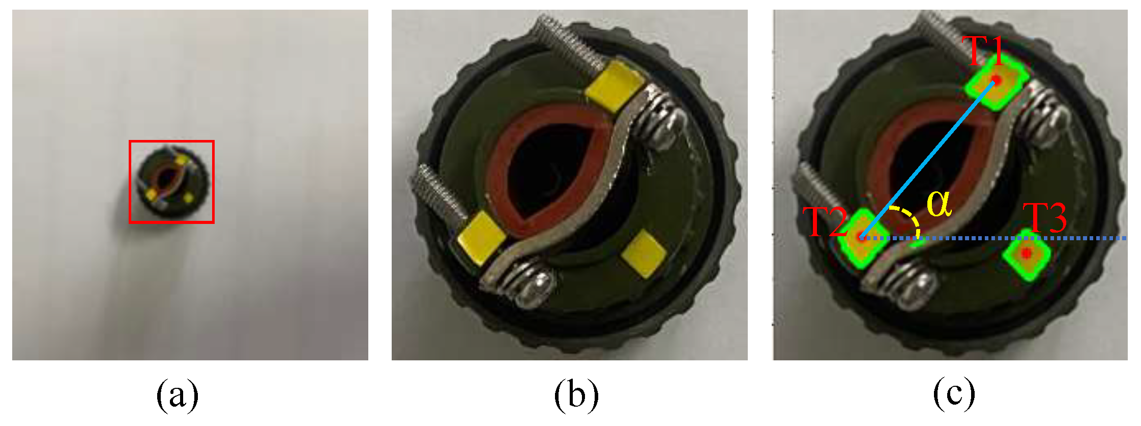
3.1.1. Detection and Localization of the MPCC

With the continuous advancement of deep learning technology, convolutional neural network (CNN)-based object detection methods have matured significantly. In this study, to enhance detection efficiency and speed, we employ RT-DETR for the detection and localization of the MPCC female. RT-DETR features high detection accuracy and real-time processing capabilities, making it suitable for rapid detection in dynamic environments. We use RGB images, denoted as I r g b , as the input and output of the bounding boxes of the MPCC female in the image. The function f d ( I r g b , θ ) utilizes pretrained neural network weights θ to process the input image and generate the bounding box ( x min , x max , y min , y max ) , where x min , x max , y min , y max are the pixel coordinates of the bounding box. After obtaining the bounding box of the MPCC female, we can calculate the image coordinates of the center position of the MPCC female, denoted as ( x ^ , y ^ ) , due to the symmetry of the rectangle, using Equation (1).
x ^ = x max + x min 2 , y ^ = y max + y min 2
The next step involves converting the image coordinates of the MPCC female into world coordinates. Let M = ( x i , y i , z i ) , where 1 i 9 represents the world coordinates of the nine circle centers in Figure 3. Then, the Canny edge detection algorithm is employed to detect the edges in the image, followed by calculating the average position of these edge points (the center of the circle) P = ( u i , v i ) , where 1 i 9 corresponds to the image coordinates of the nine circle centers in M . The values of ( x i , y i , z i ) on the M panel are fixed, with z i representing the height of the M panel in world coordinates. During the position calculation process, the MPCC female is located on the M panel and the height remains constant; thus, z i is considered a constant. In this work, calibration is performed using homography. Equation (1) describes the homography calibration method, which transforms the point set P (image coordinates) from the image captured by the camera (handheld) into the point set R (world coordinates) in the robot’s 3D operation using a 3 × 3 homography matrix H.
P H = R where P = u 1 v 1 1 u n v n 1 , H = h 11 h 12 h 13 h 21 h 22 h 23 h 31 h 32 h 33 , R = x 1 y 1 1 x n y n 1
In Equation (2), the homography H contains nine variables. When m 4 , we can obtain a solution for H. In this way, the image coordinates of the MPCC female are calibrated to world coordinates, and the same method can be used to obtain the world coordinates of the MPCC male.

3.1.2. Yaw Angle Estimation for the MPCC Female

As shown in Figure 4a,b, the bounding box of the MPCC female is cropped. In Figure 4c, the required rotation angle is determined by calculating the centroid positions of the three yellow regions on the top of the MPCC female. First, the image is converted from the RGB color space to the HSV color space. The HSV threshold for yellow is determined through calibration, and a binary mask is created to isolate the yellow regions. Next, morphological opening is used to reduce image noise and remove isolated pixels, followed by Canny edge detection to identify contours. The contours of the three yellow regions are drawn with green lines in the image, and the centroids T i ( c x i , c y i ) 1 i 3 are calculated using (3), where M 00 is the area of the contour region and M 10 and M 01 are the first-order moments in the x and y directions, respectively.
c x i = M 10 M 00 , c y i = M 01 M 00
As illustrated in Figure 4c, the angle φ between T 1 T 2 and the x-axis of the image is the angle that the robotic arm needs to adjust. By using (4) to determine the relative position (left or right) of T 3 with respect to the edge T 1 T 2 , it is possible to decide whether to perform a 180° rotation adjustment on the image. The angle θ is the rotation angle for the robotic arm to grasp the MPCC female.
φ = c y 3 c y 2 c y 1 c y 2 c x 3 c x 2 c x 1 c x 2 , θ = arctan c y 2 c y 1 c x 2 c x 1 φ 0 arctan c y 2 c y 1 c x 2 c x 1 + π φ < 0
By obtaining the world coordinates and the rotation angle θ of the MPCC female and using the above method, the MPCC female can be grasped from the material panel and placed onto the assembly panel for coupling.

3.2. DSNN-Driven Alignment for MPCC

3.2.1. Visual Perception

As shown in the visual perception section of Figure 5, the assembly of a Multi-Pin Circular Connector (MPCC) cannot be observed from a top-down view. Therefore, this study employs an RGB camera to capture images of the MPCC assembly in the x-axis and y-axis directions of the robotic arm coordinate system. We use a host computer to control the robotic arm to assemble the MPCC to the ideal position and take an image of this position as the standard image. Subsequently, by randomly moving the robotic arm within a restricted range, we generate deviation images. We use RT-DETR to crop out the assembly parts and adjust the image resolution to 224 × 224 × 3, making the input image suitable for the resolution required by the Deep Siamese Neural Network (DSNN).

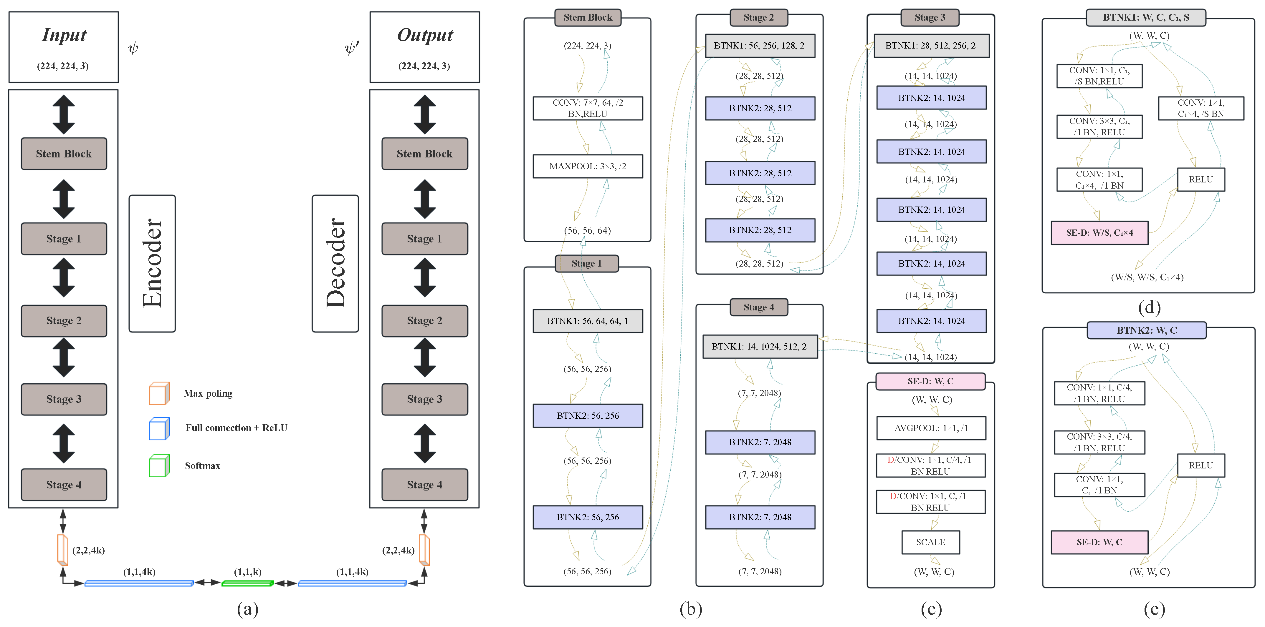
3.2.2. Feature Extraction

As shown in the feature extraction section in Figure 5, we use the adjusted standard image and deviation image as inputs and employ a CNN-based autoencoder to encode both, resulting in a one-dimensional feature vector with k ( k = 1024 ) components. We select the ResNetSED-50 model integrated with attention modules for feature extraction. Initially, in the stem block phase, the image undergoes preprocessing through preliminary convolution, normalization, activation, and pooling operations, extracting fundamental features from the input image and significantly reducing the feature map size [23]. Subsequently, the image is processed through four regular stages, transforming a 224 × 224 × 3 image into a 7 × 7 × 2048 feature block. Then, we use a max-pooling operation to convert the 7 × 7 × 2048 feature block into a 1 × 1 × 4 K feature block, and, through fully connected layers of 4K-2K-K, we compress the 4K features into K features. Figure 6a details the architecture of the ResNetSED-50 autoencoder, where the left column shows the encoding process and the right column shows the decoding process. It is worth noting that the encoding phase includes the application of attention modules whereas the decoding phase does not; the image is reconstructed through transposed convolution to ensure structural symmetry. Figure 6b details the five stages of ResNetSED-50 (from stem block to Stage 4), where the yellow and green dashed arrows represent the encoding (convolution) and decoding (transposed convolution) processes, respectively. Except for the stem block stage, the other four stages (Stage 1 to Stage 4) mainly contain two types of network structures: BTNK1 (W, C, C1, S) and BTNK2 (W, C). Here, C 1 is the number of output channels of the network (if C = C 1 , the number of channels remains unchanged; if C > C 1 , the number of channels is reduced), and S represents the downsampling ratio. Figure 6d,e detail the network structures of BTNK1 and BTNK2, respectively. Compared to BTNK2, BTNK1 adds an additional convolution and normalization step to adjust the input and output channels. We proposed an improved SE-D module based on the SE [24] module and incorporated it into the BTNK1 and BTNK2 encoding processes. Figure 6c shows the network structure of SE-D, where D/CONV represents depthwise separable convolution, and SCALE is used to apply the generated channel attention weights to the original input feature map, weighting each channel to enhance key features and suppress non-key features. We replaced the fully connected layers in the SE module with 1 × 1 depthwise separable convolutions and introduced BN (batch normalization) and ReLU activation functions. This reduces the model’s parameter count and computation while improving computational efficiency, training stability, and generalization ability, thereby strengthening the learning and expression of important features. To optimize the model, we used stochastic gradient descent (SGD) as the optimizer, ReLU activation functions in the convolutional layers, and Euclidean-distance-based logistic regression as the loss function at the end of the fully connected layers.
f t = σ ( W f · h t 1 , X t + b f )
i t = σ ( W i · h t 1 , X t + b i )
C ˜ t = tanh ( W C · h t 1 , X t + b C )
C t = f t · C t 1 + i t · C ˜ t
o t = σ ( W o · h t 1 , X t + b o )
h t = o t · tanh ( C t )

3.2.3. Regression for Position Identification

As illustrated in Figure 5, “Regression for Position Identification”, we input these feature vectors into the regression module to obtain the deviations Δ x and Δ y along the x-axis and y-axis in the robot arm’s coordinate system. The training process continues until the minimum deviation requirement for Multi-Pin Circular Connector (MPCC) assembly is met. The autoencoder converts each 224 × 224 × 3 image into a feature vector of length K. Subsequently, an LSTM network learns actions from the combined temporal features X t ( 1 t T ) obtained from the autoencoder. The process of LSTM is given by Equations (5)–(10). X t is the input to the LSTM unit with a length of 2K. The LSTM contains three main gating units: the forget gate ( f t ), the input gate ( i t , C ˜ t , C t ), and the output gate ( o t , h t ). The LSTM first determines which previous memories ( C t 1 ) to forget through the forget gate ( f t ), then updates the cell state ( C t ) via the input gate ( i t ) and candidate values ( C ˜ t ), and finally generates the current hidden state ( h t ) through the output gate ( o t ).
In this study, we constructed an LSTM network with a two-layer hidden structure, where the number of hidden units per layer is 2K, K, and K/2, respectively. This LSTM network first processes a 2K-dimensional input feature vector, with the first K dimensions derived from the deviation image and the last K dimensions from the standard image. The network then transforms these features into a K/2-dimensional intermediate feature vector Y. To map the features to the output vector, we deployed a lightweight fully connected (FC) neural network before the softmax processing, with a hierarchical structure of K/2-K/4-16-2. Through this configuration, the K/2-dimensional features are efficiently mapped to the final output vector: Δ x and Δ y .

3.3. Robot Assembly Online Control

Algorithm 1 control presents the online iterative process of robot operations. In Algorithm 1 control, the calculations of Δ x and Δ y are essential. D x and D y represent the maximum error tolerances in the x and y axes of the robotic arm coordinate system during the assembly of the Multi-Pin Circular Connector (MPCC). After obtaining Δ x and Δ y , the system evaluates whether the MPCC position has been correctly identified. Once the conditions are met, the system connects the MPCC female to the male. Otherwise, the system moves the manipulator to a new position α t = α t 1 + f ( Δ x , Δ y ) . Here, α t = ( x t , y t ) and α t 1 = ( x t 1 , y t ) are the two consecutive assembly positions at frames t 1 and t, respectively, and f ( ) is a constant matrix used to calibrate and transfer the movement distance in the visual image plane to the robot’s motion space [2]. The values of D x and D y are 0.8 mm and 0.8 mm, respectively. At the start of Algorithm 1 control, the initial position of the MPCC is generated by RT-DETR, denoted as ( x 0 , y 0 ). As shown in Equation (11), Ω ( t , Δ x , Δ x ) is used to determine whether to terminate the iteration. In the formula, T represents the maximum number of iterations, which is set to 7. In the subsequent experimental section, we will explain in detail why the maximum number of iterations is set to 7. The green arrows in Figure 5 indicate the online process of Algorithm 1 control for MPCC position identification. After aligning the MPCC, we use the empirical angles obtained from the host computer’s teaching to screw and fasten the MPCC.
Ω ( t , Δ x , Δ y ) = True , ( ( t T )   &   &   ( Δ x D x   &   &   Δ y D y ) ) False , others
Algorithm 1 Control ( { x t 1 } , { y t 1 } , t , T , { D x } , { D y } , x , y )
1: While  ( t T ) AndAnd ( | x | { D x } AndAnd | y | { D y } )
2:   α t ( x t , y t ) = α t 1 ( x t 1 , y t 1 ) + f ( x , y )
3:   transfer to ( x t , y t )
4:   ( x , y ) = D S N N ( x t , y t )
5:   t + +
6:   if  ( TRUE = = Ω ( t , x , y ) )
7:      return;
8:   Else
9:      Control  ( x t , y t , t , T , D x , D y , x , y )

4. Experiments and Results

4.1. Experiment Platform

As shown in Figure 7a, our experimental platform primarily includes a 6-DOF Universal Robots UR5 robotic arm, a Robotiq 2F-85 gripper, and two RGB cameras. The MPCC model that we assembled is Y2-3TK (yellow rectangular frame). The specific shape of the Y2-3TK is shown in Figure 1: Figure 1a illustrates the MPCC female with a maximum diameter of 22.7 mm whose housing is made of cast aluminum alloy, and the connector holes c i ( 1 i 3 ) have a diameter of 2.5 mm; Figure 1b shows the MPCC male with a maximum diameter of 31 mm, also made of cast aluminum alloy, with internal pins r i ( 1 i 3 ) made of gold-plated copper alloy, having a diameter of 2 mm. The blue parts in Figure 1a,b represent insulating materials made from thermosetting polymers. This connector features a compact size, light weight, ease of use, durability for repeated insertions, excellent conductivity, and good sealing properties. It is widely used for line connections in various electrical devices, instruments, and meters. Moreover, compared to three-pin components, two-pin and four-pin components are easier to assemble due to their lower precision alignment requirements and easier handling in terms of space and stability. Therefore, this experiment is also applicable to the assembly tasks of Y2-2TK and Y2-4TK MPCCs.
As depicted in Figure 7a, at the start of the experiment, the MPCC female is placed on the material panel (blue rectangular frame), while the male is fixed on the assembly panel (red rectangular frame). It can be observed from Figure 7b that, during the assembly process by the robotic arm, the pins of the MPCC are not visible. Therefore, ensuring the alignment of the MPCC female and male during insertion is critical and challenging. Figure 7b presents snapshots of the MPCC assembly process from gripping to screwing, conducted using the method described in Section 3.

4.2. Calibration Errors

We captured 150 images of 640 × 480 resolution at arbitrary positions on the material panel to train the RT-DETR-R18 [17]. The images were manually annotated with bounding boxes and types. We used 120 annotated images as the training set, 20 images as the validation set, and 10 images as the test set. The training was conducted on a computer equipped with an Intel(R) Core(TM) i9-9900K 3.60 GHz CPU, 32 GB of RAM, and a V100 GPU with 16 GB of memory. The batch size was set to 2, and the number of training epochs was set to 300. After the training was completed, the model was deployed on a computer equipped with a 4.00 GHz Intel(R) Core(TM) i7-6700K CPU, 16.0 GB of RAM, and an NVIDIA GeForce GTX 1080 GPU, as shown in Figure 7a. Since the MPCC assembly requires screwing, it was fixed to the assembly panel.
During the experiment, the images captured by the camera were calibrated to the robot operating platform. The MPCC female was placed on the material panel shown in Figure 7a. Subsequently, the images captured by the camera were calibrated to the robot operating platform, and the MPCC was initially assembled using the method described in Section 3.1, where the rotational angle error of the MPCC female was negligible. However, in practical assembly, due to environmental changes or equipment vibrations, the calibration process may drift, leading to calibration errors. In our experiment, we evenly distributed the calibration points across the entire calibration board, ensured that the equipment was securely mounted, and obtained an average error of 1.31 mm along the x-axis and 1.15 mm along the y-axis by averaging the results of 50 calibrations. Considering that the maximum allowable error for the x and y axes during MPCC assembly is 0.8 mm, further adjustments are necessary. In Section 4.3, we will provide a detailed explanation of the experiment involving the alignment of the MPCC female and male using DSNN.

4.3. Performance Evaluation

4.3.1. Data Collection

We took the center position of the MPCC female as the reference point and randomly sampled a total of 12,000 error positions within the range of | | Δ x | | 2.6 mm and | | Δ y | | 2.6 mm to obtain images used as input data for the DSNN model. These data were divided into training, validation, and test sets in a 7:2:1 ratio. During the regression analysis, the value ranges of Δ x and Δ y were linearly scaled from [ 2.6 mm , 2.6 mm ] to [ 0.0 , 1.0 ] . During the data collection process, we included images with varying lighting conditions in the dataset to enhance the system’s robustness and generalization capabilities. Given the stringent precision requirements for MPCC assembly, our current focus has been on improving assembly success rates and reducing errors, and we have conducted relevant experiments.

4.3.2. Autoencoder

Figure 8a and Figure 8b, respectively, show the statistical error curves of the proposed DSNN’s autoencoder performance along the x and y axes on image samples from 12,000 random positions. The samples were rotated in a 7:2:1 ratio for training, evaluation, and testing. In Figure 8, there are four types of image data inputs: original images, VGG-16(1024), ResNet-50(1024), and ResNetSED-50(1024) with SE-D modules. The original images indicate that the image data are directly input into the DSNN structure without any transformation, while VGG-16(1024), ResNet-50(1024), and ResNetSED-50(1024) represent images encoded into k (=1024) dimensional feature vectors before being input into the DSNN. As shown in Figure 8, images based on autoencoder regression exhibit significantly better performance compared to original image regression. Moreover, ResNetSED-50(1024) shows a better error reduction trend than VGG-16(1024) and ResNet-50(1024), achieving an assembly maximum error within 0.8 mm after five to six regressions from the initial x and y axis errors of 2.6 mm. For MPCC assembly in this study, a successful assembly is achieved when the errors on the x and y axes are within 0.8 mm. Therefore, the value of T in { X t } ( 1 t T ) is set to 7.

4.3.3. DSNN Structures

We analyze the performance of the proposed method in the practical MPCC assembly environment. We continue to compare different variants of the proposed DSNN structure with state-of-the-art (SOTA) methods on image samples from 12,000 random positions, with the training, evaluation, and test sets adjusted in a 7:2:1 ratio for error correction. Therefore, approximately 8400 data pairs are fed into the proposed DSNN to regress the shift error. The UR5 robotic arm is connected to the computer via the TCP/IP protocol. During the training process, the proposed DSNN model is trained and deployed on a computer with the same configuration as the RE-DETR-R18. Training the deep learning network on 8400 image pairs takes approximately five hours. Table 1 presents the results of different DSNN structures compared to the Siamese neural network structures introduced in [2,25]. The feature vector lengths of VGG-16, ResNet-50, ResNetSED-50, and LSTM encoding are all 1024 dimensions. The FC module is the fully connected neural network following the article [25], passing the 2K feature vector to the robot action. The learning rate for LSTM training is 0.0001.
In Table 1, M ( x , y ) , M ( x , y ) , and M ¯ ( x , y ) represent the maximum, minimum, and average values of M at the (x,y) coordinates, respectively, obtained by (12)–(14). In the formulas, m i and m i are the predicted and true values of an item in M, and N is the number of samples in the evaluation or test set.
M ( x , y ) = max i = 1 N | m i m i |
M ( x , y ) = min i = 1 N | m i m i |
M ¯ ( x , y ) = i = 1 N | m i m i | N
From Table 1, it can be seen that the values in the last four rows are lower than those in the top row. This indicates that the performance of the Siamese Neural Network (DSNN) is significantly better than the VGG-16+FC model proposed in [25]. Furthermore, for two similar Siamese neural network structures, DSNN+ResNet-50+LSTM in the fourth row and DT+VGG-16+LSTM in the second row, the values for the former are notably lower than those for the latter. The main difference is that the latter uses ResNet-50 as the autoencoder instead of VGG-16, suggesting that ResNet-50 is more efficient and effective in feature extraction and processing compared to VGG-16.
In the fourth row, the values for the DSNN+ResNet-50+LSTM model are lower than those for the DSNN+ResNet-50+FC model in the third row. This indicates that the current optimal assembly position is achieved by combining previous visual inputs with the sequential process of LSTM in MPCC assembly, where LSTM performs better than the Fully Connected (FC) layer when using the DSNN structure for MPCC assembly.
Lastly, the values in the fourth row of Table 1 are significantly lower than those in the fifth row, indicating that using the proposed ResNetSED-50 within the DSNN structure results in lower errors on the x and y axes compared to the original ResNet-50. Therefore, it is evident that using the DSNN with the improved ResNetSED-50 model as the autoencoder helps to achieve the highest accuracy in MPCC assembly positioning.

4.3.4. Performance in Practical Assembly

We compared the success rate and buckling time of the robotic assembly before connection using VGG-16+FC [25], DT-driven DT+VGG16+LSTM [26], and the proposed ResNetSED-50 model. A total of 800 practical experiments were conducted on the assembly platform. Figure 9 shows the comparison results. During the buckling servo process, after adjusting and calculating the MPCC position, we adopted a circular spiral trajectory servo strategy [26], buckling the MPCC male and MPCC female around the predicted point at 0.1 mm intervals in the directions of up, left, down, right, upper left, lower left, lower right, and upper right. As shown in Figure 9, under the constraints of 1, 5, and 10 buckling times, the assembly success rates of this method were 83.1%, 91.3%, and 97.4%, respectively, outperforming VGG-16+FC (49.3%, 69.2%, and 76.2%) and DT+VGG-16+LSTM (66.5%, 78.4%, and 89.7%). This method achieved a success rate of 83.1%, with a maximum of 1 buckling time, superior to DT+VGG-16+LSTM under 5 buckling times and VGG-16+FC under 10 buckling times. Overall, the proposed DSNN+ResNetSED-50+LSTM network resulted in 16.6%, 12.9%, and 7.7% higher assembly success rates than the DT+VGG-16+LSTM method under 1, 5, and 10 buckling time constraints, respectively.
Furthermore, Table 2 summarizes the parameter counts, response times, average x and y axis errors in actual assembly, and success rates for the VGG-16+FC [25], DT-driven DT+VGG16+LSTM [2], and our proposed DSNN+AE(ResNetSED-50)+LSTM models, providing a more comprehensive and clear comparison of the performance of each model. The data show that our proposed DSNN+AE(ResNetSED-50)+LSTM model achieved a response time of 43 ms with a parameter count of 98.4M. In comparison, VGG16 + FC has a parameter count of 145 M and a response time of 63 ms, while DT+VGG-16+LSTM has a parameter count of 184 M and a response time of 88 ms. Our model not only excels in response time (approximately 31.7% faster than VGG16 + FC and 51.1% faster than DT+VGG-16+LSTM) but also significantly reduces the average x and y axis errors to 0.28 mm and 0.27 mm, respectively, which are much lower than those of the other models. This indicates that our design optimizations have not only improved computational efficiency and response speed but also significantly enhanced assembly accuracy. Additionally, DSNN+AE(ResNetSED-50)+LSTM achieved a success rate of 83.1% under a single buckling time, significantly outperforming the other models, further validating the reliability and superiority of this model in MPCC assembly tasks.

4.3.5. Ablation Study

In this section, we analyze the contribution of each component to the overall system performance through an ablation study. Table 3 presents the success rates and their averages for the MPCC system as each component is gradually added, under the conditions of 1, 5, and 10 allowed assembly attempts. Since RT-DETR-18 serves as the initial assembly model for the system, we use RT-DETR-18 as the baseline model and adopt a method of incrementally adding components to visually demonstrate the impact of each additional module on the system’s performance. Given that the DSNN requires a feature extraction model, we use ResNet-50 as the baseline for comparison with ResNetSED-50 to evaluate their respective effects.
The data from the first and second rows indicate that the introduction of the DSNN with ResNet-50 as the feature extraction model increased the success rates under the assembly constraints of 1, 5, and 10 attempts by 33.5%, 25.3%, and 19.1%, respectively, with an average success rate improvement of 26%. This demonstrates that the inclusion of the DSNN significantly enhances the success rate of the MPCC assembly system. Furthermore, the comparison between the second and third rows shows that replacing ResNet-50 with ResNetSED-50 resulted in success rate increases of 7.2%, 6.3%, and 4.8% for 1, 5, and 10 assembly attempts, respectively, with an average improvement of 6.1%. This indicates that the ResNetSED-50, integrated with the SED module, exhibits superior performance in feature extraction.
Further analysis of the data from the third and fourth rows reveals that the use of the DSNN encoded with the ResNetSED-50-based autoencoder resulted in success rate improvements of 6.8%, 3.2%, and 2.5% for 1, 5, and 10 assembly attempts, respectively, compared to the scenario without an autoencoder, with an average improvement of 4.2%. Finally, the comparison between the fourth and fifth rows shows that including LSTM led to success rate increases of 1.5%, 2.6%, and 1.7% under the same assembly constraints, with an average improvement of 1.9%. This indicates that, when using the DSNN architecture for MPCC female assembly, LSTM outperforms traditional Fully Connected (FC) layers in handling temporal information. In conclusion, each component contributes significantly to enhancing system performance, with the integration of the DSNN and ResNetSED-50 being particularly crucial for overall performance improvement.

4.4. Discussions

In this experiment, we used the Y2-3TK model of the three-pin MPCC as the primary research subject. Since the assembly of the three-pin component is more challenging compared to the two-pin and four-pin components, our experiment is also applicable to the assembly tasks of Y2-2TK and Y2-4TK models of MPCCs. During the experiments, we manipulated the robotic arm and collected 12,000 random displacement error data points on a self-constructed Multi-Pin Circular Connector (MPCC) assembly platform. The data indicate that the displacement errors | | Δ x | | and | | Δ y | | do not exceed 2.6 mm. These error boundaries stem from the initial errors obtained through visual methods. In our MPCC assembly system, the target position of the MPCC male on the assembly panel is predetermined. Therefore, the ideal target position of the MPCC male can be accurately determined in advance. The robotic arm is guided to the target position of the MPCC male to obtain standard images. Using manually collected data, we compared the performance of the DSNN structure using raw images and using k-dimensional feature vectors encoded by VGG-16, ResNet-50, and ResNetSED-50 as inputs. Experimental results indicate that ResNetSED-50 outperforms raw visual images, VGG-16, and ResNet-50, achieving an assembly maximum error of within 0.8 mm from the initial 2.6 mm in five to six regressions on the x and y axes.
Furthermore, we compared the proposed DSNN variant with state-of-the-art (SOTA) structures on training, evaluation, and test sets of 12,000 random samples (in a 7:2:1 ratio) to achieve position recognition performance. Statistical data show that the proposed DSNN structure guided by the ResNetSED-50 autoencoder strategy outperforms SOTA methods: VGG-16+FC [25] and digital twin (DT)-driven DT+VGG-16+LSTM [2]. On the actual MPCC assembly platform, we used the DSNN model incorporating the proposed ResNetSED-50 as an autoencoder. This paper employs the RT-DETR method to obtain the initial positions of the MPCC female and male. Once the initial positions are determined, the proposed method can be used to align the male and female. The experimental results demonstrate that, given the initial visual MPCC positions, our proposed ResNetSED-50-based DSNN structure achieves a higher success rate under different buckling time constraints compared to the current SOTA methods DT+VGG-16+LSTM and VGG-16+FC. This method achieves success rates of 83.1% and 91.3% under one-time and five-time buckling constraints, respectively. Additionally, our experimental results also show that the DSNN+AE (ResNetSED-50) + LSTM model has a higher computational efficiency and faster response speed compared to other models. This is particularly useful in the actual MPCC assembly process, as reducing the buckling time between the MPCC female and male can effectively protect the pins inside the MPCC from potential bending or damage.
Further ablation experiments indicate that the incremental addition of components in the MPCC assembly system significantly enhances overall system performance. The introduction of the DSNN and ResNetSED-50, in particular, has markedly improved success rates and feature extraction capabilities. Moreover, integrating the autoencoder and LSTM models has further enhanced the system’s performance in handling complex feature representations. These experimental results demonstrate that our proposed method offers significant advantages in improving the overall performance of MPCC assembly tasks.

5. Conclusions

This paper proposes a vision-based six-dimensional robotic axis-hole assembly strategy that effectively addresses the alignment challenge of axis-hole during the assembly of Multi-Pin Circular Connectors (MPCCs). Compared to traditional force feedback and deep reinforcement learning approaches, the Deep Siamese Neural Network (DSNN) model proposed in this paper avoids the difficulties of modeling and long training times, achieving a comprehensive assembly system from initial gripping to final screwing. A homography-based strategy is introduced in the system to calibrate the world coordinates and image coordinates of the operating panel. This strategy utilizes the geometric relationship between two planar images to achieve precise coordinate transformation. In addition, this paper uses the ResNetSED-50 model as the backbone structure of the DSNN. The model integrates the SE-D attention module, which replaces the fully connected layers in the SE module with depthwise separable convolutions, thereby enhancing the learning and representation of important features. The experimental results show that, in MPCC assembly, our method achieves a higher success rate under various allowed maximum assembly attempts compared to existing state-of-the-art technologies, with overall assembly success rates being satisfactory. We have also identified some limitations in our system. As the number of pins increases, the robotic arm may experience insufficient gripping force, leading to the connectors slipping from the gripper during the screwing process. To address this issue, we plan to optimize the gripper design in future research and use high-friction materials to enhance the gripping force of the robotic arm, thereby improving the system’s robustness and adaptability.
In future work, we plan to evaluate the system’s performance in more complex assembly tasks, such as handling components with more pins and accommodating connectors of different shapes and sizes. These complex tasks place higher demands on the system’s precision and adaptability. To address these challenges, one potential solution is to integrate tactile and visual information. By combining these two sensory capabilities, the system can more effectively manage assembly issues caused by complex part geometries or positioning errors, thereby enhancing precision and adaptability.

Author Contributions

Conceptualization, W.T.; methodology, W.T.; validation, W.T.; formal analysis, W.T., J.C. and M.Y.; investigation, W.T.; resources, W.T.; data curation, W.T.; writing—original draft preparation, W.T. and M.Y.; writing—review and editing, W.T. and M.Y.; visualization, W.T.; supervision, M.Y. and J.C.; project administration, J.C. All authors have read and agreed to the published version of the manuscript.

Funding

This work was funded by the Guangxi Science and Technology Development Project (AB23026135; AB21220011) and the Guilin Science and Technology Plan Project (20210220).

Data Availability Statement

Data are contained within the article.

Conflicts of Interest

The authors declare no conflicts of interest.

Abbreviations

The following abbreviations are used in this manuscript:
MPCCMulti-Pin Circular Connector
DSNNDeep Siamese Neural Network
SE-DSqueeze-and-Excitation with Depthwise separable convolutions
ResNetSED-50ResNet50 integrated with SE-D module.
RT18RT-DETR-18
AEAutoEncoder

References

  1. Arents, J.; Greitans, M. Smart industrial robot control trends, challenges and opportunities within manufacturing. Appl. Sci. 2022, 12, 937. [Google Scholar] [CrossRef]
  2. Yang, M.; Huang, Z.; Sun, Y.; Zhao, Y.; Sun, R.; Sun, Q.; Chen, J.; Qiang, B.; Wang, J.; Sun, F. Digital twin driven measurement in robotic flexible printed circuit assembly. IEEE Trans. Instrum. Meas. 2023, 72, 5007812. [Google Scholar] [CrossRef]
  3. Kyrarini, M.; Haseeb, M.A.; Ristić-Durrant, D.; Gräser, A. Robot learning of industrial assembly task via human demonstrations. Auton. Robot. 2019, 43, 239–257. [Google Scholar] [CrossRef]
  4. Lee, Y.; Hu, E.S.; Lim, J.J. IKEA furniture assembly environment for long-horizon complex manipulation tasks. In Proceedings of the 2021 IEEE International Conference on Robotics and Automation (ICRA), Xian, China, 30 May–5 June 2021; pp. 6343–6349. [Google Scholar]
  5. Zhang, K.; Wang, C.; Chen, H.; Pan, J.; Wang, M.Y.; Zhang, W. Vision-based six-dimensional peg-in-hole for practical connector insertion. In Proceedings of the 2023 IEEE International Conference on Robotics and Automation (ICRA), London, UK, 29 May–2 June 2023; pp. 1771–1777. [Google Scholar]
  6. Schoettler, G.; Nair, A.; Luo, J.; Bahl, S.; Ojea, J.A.; Solowjow, E.; Levine, S. Deep reinforcement learning for industrial insertion tasks with visual inputs and natural rewards. In Proceedings of the 2020 IEEE/RSJ International Conference on Intelligent Robots and Systems (IROS), Las Vegas, NV, USA, 24–29 October 2020; pp. 5548–5555. [Google Scholar]
  7. Park, H.; Park, J.; Lee, D.-H.; Park, J.-H.; Baeg, M.-H.; Bae, J.-H. Compliance-based robotic peg-in-hole assembly strategy without force feedback. IEEE Trans. Ind. Electron. 2017, 64, 6299–6309. [Google Scholar] [CrossRef]
  8. Triyonoputro, J.C.; Wan, W.; Harada, K. Quickly inserting pegs into uncertain holes using multi-view images and deep network trained on synthetic data. In Proceedings of the 2019 IEEE/RSJ International Conference on Intelligent Robots and Systems (IROS), Macau, China, 3–8 November 2019; pp. 5792–5799. [Google Scholar]
  9. Xu, J.; Hou, Z.; Wang, W.; Xu, B.; Zhang, K.; Chen, K. Feedback deep deterministic policy gradient with fuzzy reward for robotic multiple peg-in-hole assembly tasks. IEEE Trans. Ind. Inform. 2018, 15, 1658–1667. [Google Scholar] [CrossRef]
  10. Chen, W.; Zeng, C.; Liang, H.; Sun, F.; Zhang, J. Multimodality driven impedance-based sim2real transfer learning for robotic multiple peg-in-hole assembly. IEEE Trans. Cybern. 2023, 99, 1–14. [Google Scholar] [CrossRef]
  11. Viola, P.; Jones, M. Rapid object detection using a boosted cascade of simple features. In Proceedings of the 2001 IEEE Computer Society Conference on Computer Vision and Pattern Recognition (CVPR 2001), Kauai, HI, USA, 8–14 December 2001; Volume 1, pp. 1–9. [Google Scholar]
  12. Dalal, N.; Triggs, B. Histograms of oriented gradients for human detection. In Proceedings of the 2005 IEEE Computer Society Conference on Computer Vision and Pattern Recognition (CVPR’05), San Diego, CA, USA, 20–26 June 2005; Volume 1, pp. 886–893. [Google Scholar]
  13. Girshick, R.; Donahue, J.; Darrell, T.; Malik, J. Rich feature hierarchies for accurate object detection and semantic segmentation. In Proceedings of the 2014 IEEE Conference on Computer Vision and Pattern Recognition (CVPR), Columbus, OH, USA, 23–28 June 2014; pp. 580–587. [Google Scholar]
  14. Redmon, J.; Divvala, S.; Girshick, R.; Farhadi, A. You only look once: Unified, real-time object detection. In Proceedings of the IEEE Conference on Computer Vision and Pattern Recognition, Las Vegas, NV, USA, 27–30 June 2016; pp. 779–788. [Google Scholar]
  15. Vaswani, A.; Shazeer, N.; Parmar, N.; Uszkoreit, J.; Jones, L.; Gomez, A.N.; Kaiser, Ł.; Polosukhin, I. Attention is all you need. Adv. Neural Inf. Process. Syst. 2017, 30, 1–15. [Google Scholar]
  16. Carion, N.; Massa, F.; Synnaeve, G.; Usunier, N.; Kirillov, A.; Zagoruyko, S. End-to-end object detection with transformers. In Proceedings of the European Conference on Computer Vision, Glasgow, UK, 23–28 August 2020; pp. 213–229. [Google Scholar]
  17. Zhao, Y.; Lv, W.; Xu, S.; Wei, J.; Wang, G.; Dang, Q.; Liu, Y.; Chen, J. Detrs beat yolos on real-time object detection. In Proceedings of the IEEE/CVF Conference on Computer Vision and Pattern Recognition, Seattle, WA, USA, 17–21 June 2024; pp. 16965–16974. [Google Scholar]
  18. Koch, G.; Zemel, R.; Salakhutdinov, R. Siamese neural networks for one-shot image recognition. In Proceedings of the 32nd International Conference on Machine Learning, Lille, France, 7–9 July 2015; Volume 2, Number 1. pp. 1–30. [Google Scholar]
  19. Zhang, Y.; Wang, L.; Qi, J.; Wang, D.; Feng, M.; Lu, H. Structured siamese network for real-time visual tracking. In Proceedings of the European Conference on Computer Vision (ECCV), Munich, Germany, 8–14 September 2018; pp. 351–366. [Google Scholar]
  20. Groth, O.; Hung, C.-M.; Vedaldi, A.; Posner, I. Goal-conditioned end-to-end visuomotor control for versatile skill primitives. In Proceedings of the 2021 IEEE International Conference on Robotics and Automation (ICRA), Xian, China, 30 May–5 June 2021; pp. 1319–1325. [Google Scholar]
  21. Hinton, G.E.; Salakhutdinov, R.R. Reducing the dimensionality of data with neural networks. Science 2006, 313, 504–507. [Google Scholar] [CrossRef] [PubMed]
  22. Higgins, I.; Matthey, L.; Pal, A.; Burgess, C.P.; Glorot, X.; Botvinick, M.M.; Mohamed, S.; Lerchner, A. beta-VAE: Learning basic visual concepts with a constrained variational framework. In Proceedings of the 5th International Conference on Learning Representations, ICLR 2017, Toulon, France, 24–26 April 2017. [Google Scholar]
  23. He, K.; Zhang, X.; Ren, S.; Sun, J. Deep residual learning for image recognition. In Proceedings of the IEEE Conference on Computer Vision and Pattern Recognition, Las Vegas, NV, USA, 27–30 June 2016; pp. 770–778. [Google Scholar]
  24. Hu, J.; Shen, L.; Sun, G. Squeeze-and-excitation networks. In Proceedings of the IEEE Conference on Computer Vision and Pattern Recognition, Salt Lake City, UT, USA, 18–23 June 2018; pp. 7132–7141. [Google Scholar]
  25. Pérez-Dattari, R.; Celemin, C.; Franzese, G.; Ruiz-del-Solar, J.; Kober, J. Interactive learning of temporal features for control: Shaping policies and state representations from human feedback. IEEE Robot. Autom. Mag. 2020, 27, 46–54. [Google Scholar] [CrossRef]
  26. Kang, H.; Zang, Y.; Wang, X.; Chen, Y. Uncertainty-driven spiral trajectory for robotic peg-in-hole assembly. IEEE Robot. Autom. Lett. 2022, 7, 6661–6668. [Google Scholar] [CrossRef]
Figure 1. MPCC assembly example: (a) MPCC female; (b) MPCC male; (c) unscrewed assembly drawing; (d) successful assembly drawing.
Electronics 13 03453 g001
Figure 2. Schematics of the proposed peg-in-hole system.
Electronics 13 03453 g002
Figure 3. Calibration board for converting MPCC female connector image coordinates into world coordinates.
Electronics 13 03453 g003
Figure 4. Yaw angle estimation process: (a) RT-DETR detects Multi-Pin Circular Connector (MPCC) and generates the detection bounding box; (b) cropped image of the MPCC; (c) calculation of the centroid position and rotation angle.
Electronics 13 03453 g004
Figure 5. The workflow of the proposed method.
Electronics 13 03453 g005
Figure 6. (a) The workflow of ResNetSED-50 autoencoder in this work; (b) the detailed stages of ResNetSED-50, with blue and red dashed lines representing the encoding (convolution) and decoding (deconvolution) processes, respectively; (c) the network structure of SE-D proposed in this paper; (d,e) the two main network structures used in ResNetSED-50.
Electronics 13 03453 g006
Figure 7. (a) MPCC assembly platform. (b) Snapshots of the MPCC assembly process: (1) the robotic arm moves above the MPCC female and adjusts the offset angle; (2) grasping the MPCC female; (3) the robotic arm moves the MPCC female above the male; (4) after engaging the MPCC, screwing is performed.
Electronics 13 03453 g007
Figure 8. Shows the statistical error curves of the components along the (a) x-axis and (b) y-axis as the step length increases.
Electronics 13 03453 g008
Figure 9. Comparison of MPCC assembly performance.
Electronics 13 03453 g009
Table 1. Different network structure performances.
Evaluation SetTest Set
Model Architecture X Y X Y
M M M ¯ M M M ¯ M M M ¯ M M M ¯
VGG-16+FC [25]2.850.461.322.090.320.911.260.341.061.320.220.97
DT+VGG-16+LSTM [2]1.670.270.761.490.190.530.930.420.810.850.290.66
DSNN+ResNet-50+FC0.870.120.410.650.000.380.590.210.450.530.190.42
DSNN+ResNet-50+LSTM0.630.000.310.770.000.230.650.160.390.580.120.36
DSNN+ResNetSED-50+LSTM0.420.000.160.350.000.140.450.110.280.350.000.27
The values of X and Y are in millimeters (the smaller, the better). The best, second-best, and third-best values in each column are marked in red, blue, and green, respectively.
Table 2. Performance metrics comparison.
Model ArchitectureParams (M)Response (ms)X (mm)Y (mm)Success (%)
VGG16+FC [25]145631.060.9749.3
DT+VGG-16+LSTM [2]184880.810.6669.2
DSNN+AE(ResNetSED-50)+LSTM98430.280.2783.1
Bold values represent the results from our model.“Params (M)” refers to the number of parameters in the model. “Response” indicates the time required by the model to output control instructions after receiving input data. X and Y represent the average errors in the x-axis and y-axis during the actual assembly using the model, respectively. “Success” denotes the assembly success rate of the model under a single buckling time. AE(ResNetSED-50) refers to the autoencoder based on ResNetSED-50. All models in the table are deployed on a GTX 1080 GPU.
Table 3. Ablation study.
Model ArchitectureAssembly TimesAve
1 5 10
RT1834.153.969.352.4
RT18 + DSNN + ResNet-5067.679.288.478.4
RT18 + DSNN + ResNetSED-5074.885.593.284.5
RT18+DSNN+AE(ResNetSED-50)81.688.795.788.7
RT18+DSNN+AE(ResNetSED-50)+LSTM83.191.397.490.6
Bold values represent the results from our model. The values in the table are all expressed as percentages (%), and Ave represents the average value of the row. RT18 stands for RT-DETR-18, and AE(ResNetSED-50) refers to the autoencoder based on ResNetSED-50.
Disclaimer/Publisher’s Note: The statements, opinions and data contained in all publications are solely those of the individual author(s) and contributor(s) and not of MDPI and/or the editor(s). MDPI and/or the editor(s) disclaim responsibility for any injury to people or property resulting from any ideas, methods, instructions or products referred to in the content.

