Article

Virtual Hand Deformation-Based Pseudo-Haptic Feedback for Enhanced Force Perception and Task Performance in Physically Constrained Teleoperation

1
Department of Micro-Nano Mechanical Science and Engineering, Nagoya University, Furo-cho, Chikusa-ku, Nagoya 464-8603, Japan
2
School of Engineering, The University of Tokyo, Hongo 7-3-1, Bunkyo-ku, Tokyo 113-8656, Japan
*
Author to whom correspondence should be addressed.
Robotics 2024, 13(10), 143; https://doi.org/10.3390/robotics13100143
Submission received: 13 August 2024 / Revised: 16 September 2024 / Accepted: 23 September 2024 / Published: 24 September 2024
(This article belongs to the Special Issue Extended Reality and AI Empowered Robots)

Abstract

:
Force-feedback devices enhance task performance in most robot teleoperations. However, their increased size with additional degrees of freedom can limit the robot’s applicability. To address this, an interface that visually presents force feedback is proposed, eliminating the need for bulky physical devices. Our telepresence system renders robotic hands transparent in the camera image while displaying virtual hands. The forces applied to the robot deform these virtual hands. The deformation creates an illusion that the operator’s hands are deforming, thus providing pseudo-haptic feedback. We conducted a weight comparison experiment in a virtual reality environment to evaluate force sensitivity. In addition, we conducted an object touch experiment to assess the speed of contact detection in a robot teleoperation setting. The results demonstrate that our method significantly surpasses conventional pseudo-haptic feedback in conveying force differences. Operators detected object touch 24.7% faster using virtual hand deformation compared to conditions without feedback. This matches the response times of physical force-feedback devices. This interface not only increases the operator’s force sensitivity but also matches the performance of conventional force-feedback devices without physically constraining the operator. Therefore, the interface enhances both task performance and the experience of teleoperation.

Graphical Abstract

1. Introduction

Teleoperated robots have been developed to operate in hazardous environments that are inaccessible to humans [1,2,3]. Recently, the development of these robots has extended to support the social participation of individuals with disabilities, as well as the elderly, who experience difficulty in public spaces such as public transportation systems and shopping malls or in performing housework [4]. Thus, advances in telerobotics are geared toward assisting people in daily living and improving their quality of life, as opposed to only supporting tasks in difficult environments.
To enhance the sense of social participation facilitated by teleoperated robots for operators, a system that immerses operators in robots and enables them to manipulate the robot as if it were their own body is required. For this purpose, a head-mounted display (HMD) teleoperation system was developed [5,6,7,8,9]. The HMD allows users to see three-dimensional images from the robot’s viewpoint, providing an immersive operational experience. The provision of force feedback is important for enabling operators to perform tasks remotely. Previous research has shown that force feedback improves task performance and enhances situational awareness [10,11,12]. Bilateral control is used to provide feedback on the force applied by operators to robots [13,14,15]. However, force-feedback devices are required to provide force sensations to operators. As the degrees of freedom to represent force increase, the size and weight of these devices also increase, making them difficult for operators to manipulate. In addition, the operating environment is restricted, and remote operations cannot be performed freely when the user is not at home or is traveling. Therefore, to provide force feedback to the operator without using haptic devices, we focused on pseudo-haptics, which provides force feedback through vision.
Pseudo-haptics is a phenomenon caused by a contradiction between visual and somatic sensations [16]. For example, when a user lifts a ball in real space, the virtual ball in the virtual space they are observing moves synchronously. If the amount of movement of the virtual ball is smaller than that of the ball in real space, the user will perceive the ball as being heavier than its actual weight. Conversely, if the amount of movement of the virtual ball is larger than that of the ball in real space, the user will perceive the ball as being lighter than its actual weight. It has been reported that the perception of weight can be altered by changing the ratio of the amount of movement between the user’s control object and the displayed control object (C/D ratio) [17]. Son et al. reported that it is possible to feel the weight of an object using pseudo-haptic feedback even if the user does not hold it in real space [18]. Lécuyer et al. reported that it is possible to recognize bumps and holes by changing the velocity of the mouse cursor, in contrast to changing mouse control [19]. Pseudo-haptic feedback enables an immersive and realistic experience [16,20]. Thus, pseudo-haptics is considered an effective method for presenting force without the use of force-feedback devices.
However, three problems are associated with the use of conventional pseudo-haptic feedback to perceive force in teleoperation. First, presenting conventional pseudo-haptics requires creating a gap between the movement of the manipulated robotic hand and that of the operator’s hand, resulting in spatial mismatch. This mismatch reduces the transparency and sense of agency in teleoperation, thereby decreasing the perception and immersiveness of the remote environment [21,22,23]. In conventional pseudo-haptic feedback, the amount of force sensation is changed by changing the C/D ratio [24,25,26]. However, the larger the difference in movement, the larger the spatial mismatch, as the C/D ratio is always different from 1. Second, it is difficult to determine whether an object has been touched using conventional pseudo-haptics. Conventional pseudo-haptic feedback provides a force sensation based on the difference between the movement of the user’s hand and that of the manipulated target. Therefore, recognizing touch using pseudo-haptics is challenging because there is little difference in movement when touching the object. The third problem is that it is difficult to determine the degree of force applied to an object, as it is based on the difference between the movement of the user’s hand and that of the manipulated target, which is not intuitive. Therefore, to enhance task performance in teleoperation without physically constraining the operator, a pseudo-haptic feedback method is essential that addresses three critical aspects. First, the method should minimize any discrepancy between the positions of the operator’s and the robot’s hands. Second, it should facilitate rapid recognition of force. Third, it should allow for intuitive understanding of force. The objective is to develop a pseudo-haptic feedback interface that meets these three requirements and delivers a force perception comparable to that provided by conventional force-feedback devices.
We propose an interface that displays virtual hands to embody a robot by rendering the robot’s hand transparent in camera images. As shown in Figure 1, to present pseudo-haptic feedback, the force applied to the robot deforms the virtual hands and makes the operators feel that their hands have been deformed. This interface has the following three advantages. First, virtual hands enhance the sense of ownership [27] by eliminating the discrepancies between human and robot appearances. The display of virtual hands allows users to predict their movements more easily, which is expected to improve the sense of agency [28] with the robot hands. An increased sense of ownership and agency provides an immersive experience, as if the operators are operating the robot with their own hands. Therefore, if users can perceive the illusion that their hands are deformed when the virtual hands are deformed, they will be able to feel the force sensation more easily. Second, because the amount of deformation of the virtual hands is visible, the C/D ratio does not need to be always set to other than 1 as in conventional pseudo-haptic feedback. Thus, even as the amount of movement increases, the space mismatch does not increase, unlike in conventional pseudo-haptic feedback. Finally, when the virtual hands are deformed by the force applied to the robot, users can instantly recognize that they have touched an object. Moreover, the deformation of the virtual hand facilitates the intuitive recognition of the degree of force.
To the best of our knowledge, there is no robot teleoperation interface that renders robots transparent and displays virtual hands. Furthermore, although there has been research on types of pseudo-haptic feedback of unevenness on object surfaces conveyed by virtual finger deformation [29], there is no method to present a sense of force by deforming virtual hands. This study was conducted to develop an interface that enables users to intuitively recognize forces using only visual information, as the virtual hands are deformed by the force applied to the robot. This research aimed to evaluate the fundamental performance of a newly developed interface through two distinct experiments. The first experiment investigated the minimal positional discrepancy necessary to perceive force between the operator’s and the robot’s hands in a VR environment, as well as force sensitivity. The second experiment focused on the speed and intuitiveness of force perception in a robot teleoperation setting. This study makes significant contributions to the field in several ways:
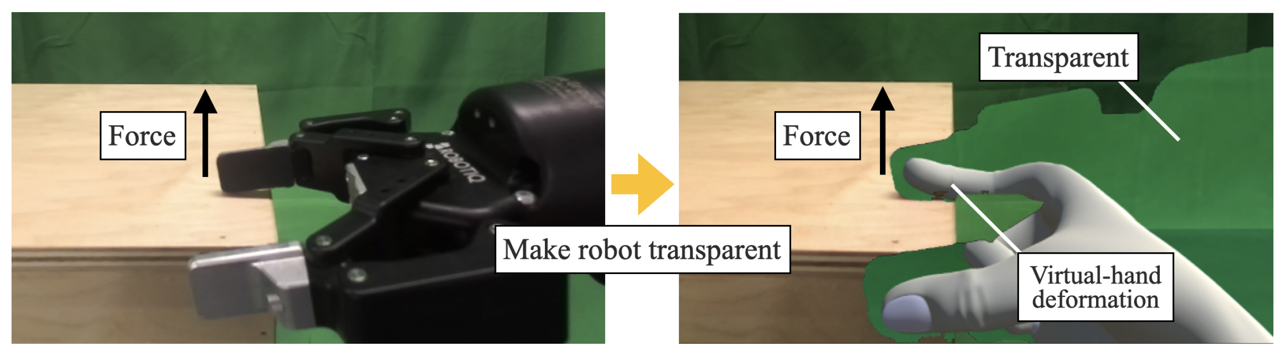
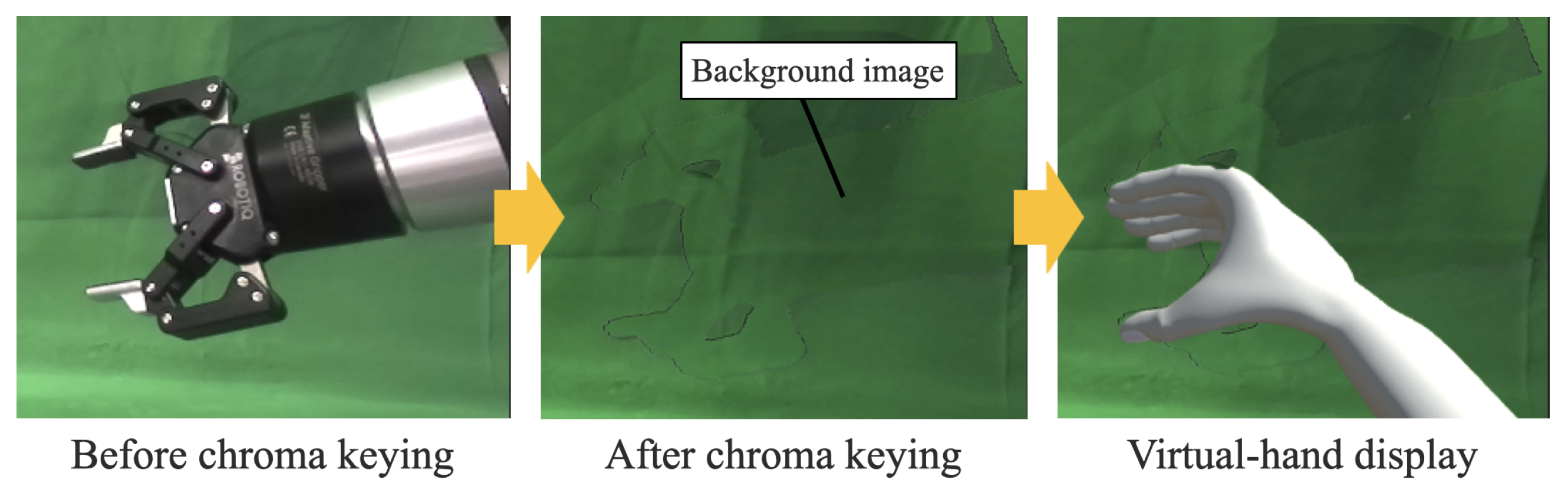
  • A teleoperation interface was developed that displays virtual hands on transparent robotic hands. This telepresence interface is designed to minimize the discrepancy between human and robot appearance and motion, thereby improving the transparency of teleoperation.
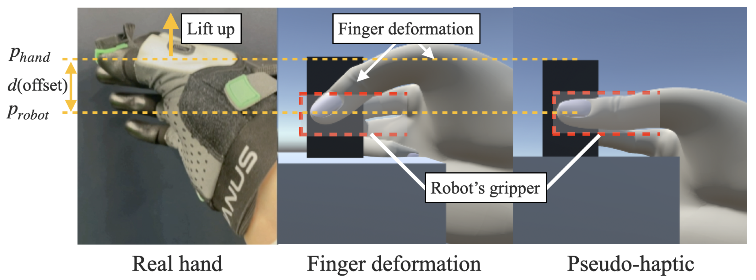
  • A system was constructed in which the displayed virtual hands were deformed by the force applied to the robotic hands. This design allows for more sensitive force perception than conventional pseudo-haptic feedback by creating the illusion that the operator’s hands are being deformed.
  • The basic performance of the proposed interface was evaluated and compared with conventional pseudo-haptic feedback systems and physical force-feedback devices, demonstrating the effectiveness of this new interface.

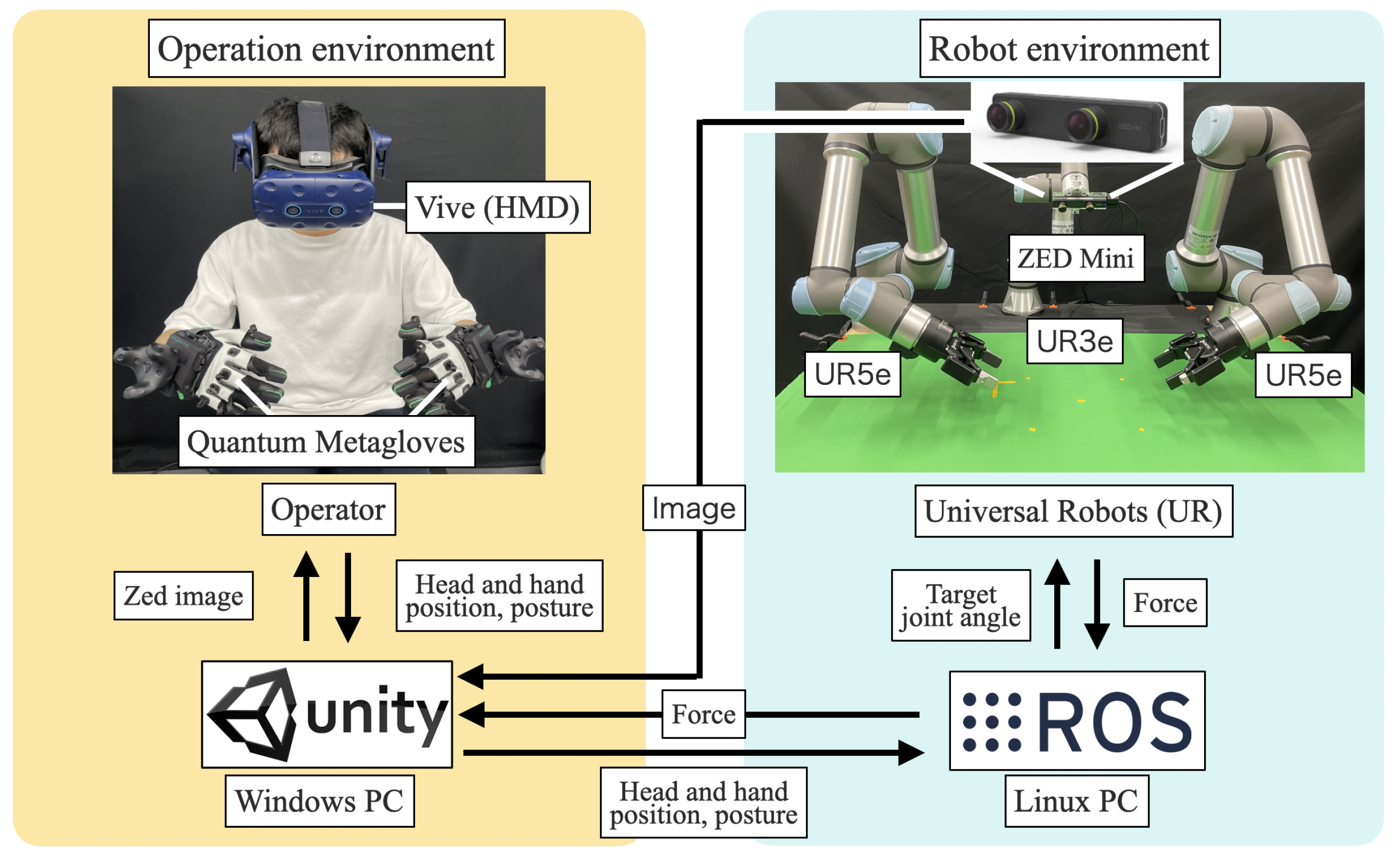
2. Teleoperation System

The device and the teleoperation system used in this study are described in this section. The teleoperation system is illustrated in Figure 2. The system uses head tracking with an HMD (HTC VIVE Pro Eye) and hand tracking with Quantum Metagloves to obtain the position and posture of the head and hands. Values were sent to the robot operating system (ROS) using the Unity3D software (2020.3.36f1). Subsequently, the inverse kinematics of the robots were solved in the ROS, and the target angles of each joint were sent to each robot (Universal Robot UR3e, UR5e). Images sent from the remote environment were captured using a stereo camera (ZED Mini, Stereo Labs) attached to one of the three robots (UR3e) at the center and sent to Unity3D. The frame rate of the images displayed on the HMD was 60. It took 50 ms for the position and posture commands to be sent and the robots to move and 130 ms to receive the images. Therefore, the operator experienced a delay of 180 ms.
The transparency of the robot at this interface was achieved using chroma-keying (a method for making certain colors transparent) in Unity3D. As shown in Figure 3, the virtual hands designed in Blender were displayed based on the transparency of the hands of the robot. The background image captured without the robot is displayed in an invisible position. In this experimental setup, the thumb and index fingers of the virtual hands are constrained to a single degree of freedom, aligned with the width of the gripper to mirror its position. This setup allows the gripper to open and close as the operator pinches their thumb and index finger in and out, respectively. The middle, ring, and pinky fingers moved synchronously with the operator’s fingers. The ZED Mini can obtain depth information; therefore, the virtual hands are hidden by real objects when they are positioned behind them.
Realistic virtual hands are displayed to enhance the operator’s sense of ownership over these appendages. Through rendering the robot transparent, the unpredictable, complex movements characteristic of multi-jointed robots can be disregarded. These movements, differing significantly from human motion, complicate prediction and diminish the operator’s sense of control. Consequently, the interface improves the operator’s sense of agency, as the virtual hand is perceived as an extension of the operator’s own limb, thereby enhancing the immersion experience. If the virtual hands are recognized as part of the operator, peri-personal space [30] is expected to expand around the robot, facilitating the operator’s adjustment to the robotic controls [31]. Within this expanded peri-personal space, operators are able to discern the positions of nearby objects more accurately, which is anticipated to improve both the speed and precision of reaching and grasping actions. However, operators often manipulate the virtual hand without due consideration for the robot’s broader movements, raising the potential for unintended collisions. To address this issue, the system was designed to prevent collisions with obstacles independently of the operator’s actions.

3. Conventional Pseudo-Haptic Feedback and Finger Deformation Methods

In this section, the conventional pseudo-haptic feedback method and the deformation of the virtual hands for each experiment are described.

3.1. Conventional Pseudo-Haptic Feedback Method in Experiment 1

To provide conventional pseudo-haptic feedback, the amount of movement of the manipulated object displayed and that of the user must be differentiated. In this study, this difference is referred to as an offset. The offset is the same as the amount of finger deformation, as shown in Figure 4.
In Experiment 1, the differences in the perception of weight were evaluated based on differences in the deformation of the virtual fingers (offset). Therefore, instead of always setting the C/D ratio to a fixed value as in conventional pseudo-haptic feedback, it was set to 1 after a specific offset was reached. However, the process of creating the offset was the same as that of conventional pseudo-haptic feedback. As confirmed in previous research, different offsets change the weight perceived by the operator [20].
In Experiment 1, the participants lifted two objects in a VR space and compared their weights. Therefore, an offset was generated in the lifting direction. The equation for changing the amount of movement of the virtual hands to create an offset is as follows:
p r o b o t _ y = p i n i _ y + α · ( p h a n d _ y p i n i _ y ) ,
where p r o b o t _ y denotes the y-axis position of the displayed virtual fingertip (robot gripper), p i n i _ y denotes the y-axis position at which the object is grasped, α denotes the C/D ratio, and p h a n d _ y denotes the actual y-axis position of the midpoint between the tips of the index finger and thumb of the operator. The operator’s perception of the weight was changed by changing the C/D ratio. For example, when the C/D ratio was low, the speed of the manipulated target was reduced, and the operator perceived the target as heavier. In this study, the C/D ratio was fixed, and the weight was changed by manipulating the offset. Based on a previous study [26], the C/D ratio was determined to be 0.18, which enabled the operator to feel the weight of the object and caused the least discomfort. The offset was determined by the weight of the object to be lifted. The equation for the target offset is as follows:
d t a r g e t = d m a x · f f m a x ,
where d t a r g e t denotes the target offset, d m a x denotes the maximum offset, f denotes the weight of the object, and f m a x denotes the maximum weight of the object to be lifted. The d m a x and f m a x can be set to the offset that is imaged when lifting the heaviest object for each user. In Experiment 1, d m a x and f m a x were set to 40 mm and 40 N, respectively. The offset equation is as follows:
d = p h a n d _ y p r o b o t _ y ,
where d denotes the offset. When the offset reaches the defined offset ( d > d t a r g e t ), the real and virtual hand movements were synchronized. The equation for the position of the virtual hand (gripper of the robot) after synchronization is as follows:
p r o b o t _ y = p h a n d _ y d t a r g e t .

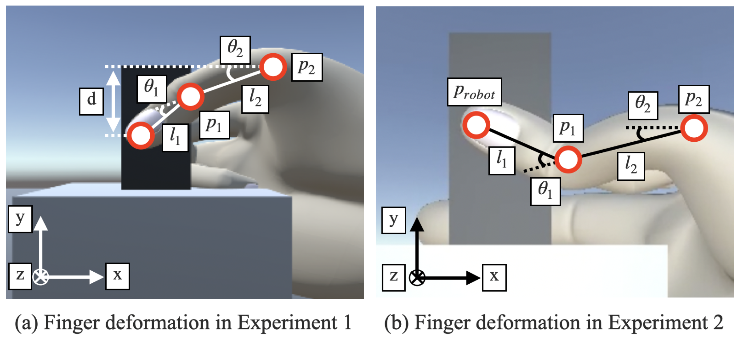
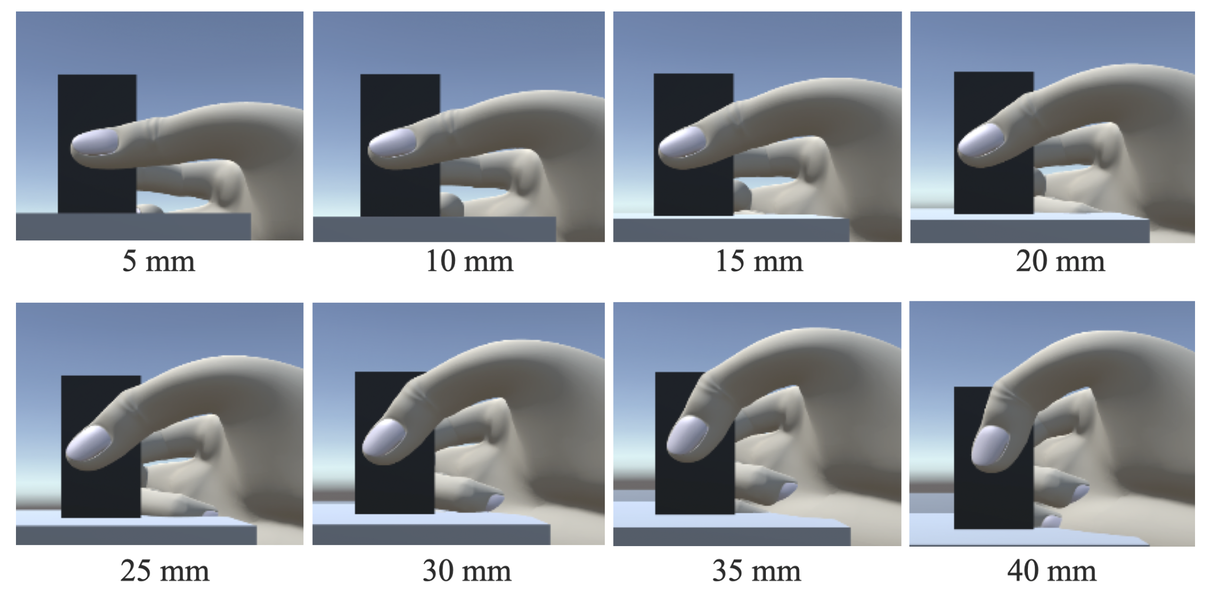
3.2. Finger Deformation Method in Experiment 1

In the virtual finger deformation method, the movements of the virtual hand and the operator’s real hand were equal. The virtual fingers are deformed based on the offset values. The change in the height of the virtual fingertip owing to virtual finger deformation was adjusted to achieve the same value as the offset. Therefore, as illustrated in Figure 4, the virtual fingertip position and movement of the grasped object are the same as those in the pseudo-haptic feedback method. By counting the joints of the fingertip, the second joint of the thumb and the second and third joints of the index finger were rotated around the z-axis, as shown in Figure 5a according to the offset value. The equation for the joint angle of the virtual finger rotated by an offset value is as follows:
θ 2 , 3 = θ m a x · d d m a x ,
where θ 2 , 3 are the angles of the second and third joints of the virtual fingers, respectively, and θ m a x is the maximum value of the joint angles of the virtual fingers. The θ m a x can be set to the amount of finger deformation imagined when lifting the heaviest object for each user. In Experiment 1, the θ m a x was set at 30 degrees. The first joints of the virtual thumb and index finger were bent to ensure that the movement of the virtual fingertip was equal to that of the offset. The equation for the first joint angle of the virtual thumb is as follows:
d = l 1 sin ( θ 1 + θ 2 ) + p 2 _ y p 1 _ y ,
θ 1 = arcsin ( d ( p 2 _ y p 1 _ y ) l 1 ) θ 2 ,
where θ 1 is the angle of the first joint of the virtual finger, p 1 _ y and p 2 _ y are the y-axis position of the first and second joints of the virtual finger, and l 1 is the x-axis distance between the virtual fingertip and first joint when the object is grasped. The angle of the first joint of the virtual index finger was determined by subtracting θ 3 from Equation (7) and substituting the y-axis position of the third joint of the index finger. When the virtual finger was bent, the grasping position shifted in the x-axis. Therefore, the virtual hand moved in the x-axis direction, such that the position of the virtual fingertip was the same as that in the x-axis direction when the object was grasped. The equation for the amount of virtual hand movement is as follows:
d v i r _ h a n d _ x = p t h u m b _ i n i _ x p t h u m b _ t i p _ x ,
where d v i r _ h a n d _ x denotes the amount of movement of the virtual hand along the x-axis, p t h u m b _ i n i _ x denotes the position of the tip of the virtual thumb along the x-axis when grasping an object, and p t h u m b _ t i p _ x denotes the position of the tip of the virtual thumb along the x-axis. However, the position of the tip of the virtual index finger in the x-direction differed from that of the thumb tip. Therefore, when the virtual hand moved along the x-axis, the third joint of the virtual index finger had to move along the x-axis. The equation for the movement of the virtual index finger is as follows:
d i n d e x _ x = p i n d e x _ i n i _ x p i n d e x _ t i p _ x ,
where d i n d e x _ x denotes the x-axis movement of the third joint of the virtual index finger, p i n d e x _ i n i _ x denotes the x-axis position of the virtual index fingertip while grasping an object, and p i n d e x _ t i p _ x denotes the x-axis position of the virtual index fingertip.

3.3. Finger Deformation Method in Experiment 2

For the touch-and-plugging judgment experiment, the virtual fingers were deformed by the force applied to the robot. If all joints were bent in the direction of the force, the grasping position was significantly shifted. Thus, the second joint of the thumb and third joint of the index finger were rotated in the direction opposite to that where the force was applied. The equation for the joint angle is as follows:
θ = θ m a x · f r o b o t f r o b o t _ m a x ,
where f r o b o t is the force applied to the gripper, and f r o b o t _ m a x is the assumed maximum force applied to the gripper. The f r o b o t _ m a x and θ m a x can be set to the force applied when the user applies the most force and the presumed amount of finger deformation for each user. In Experiment 2, the f r o b o t _ m a x was set to 40 N, and θ m a x , to 30 degrees. The second joint of the index finger was rotated in the same direction as the applied force, and the angle was determined using Equation (10). The first joints of the virtual thumb and index finger were bent such that the heights of the virtual fingertip and gripper tip were equal. The equation for the first joint angle of the virtual thumb is as follows:
θ 1 = arcsin ( p r o b o t _ y p 1 _ y l 1 ) θ 2 .
The angle of the first joint of the virtual index finger was determined by subtracting θ 3 from Equation (11). To ensure that the x-axis positions of the tips of the virtual finger and gripper were the same, the virtual hand and third joint of the virtual index finger were moved in the x-axis direction using Equations (8) and (9).

4. Experiment 1—Weight Comparison Experiment

In Experiment 1, a weight comparison experiment was conducted in a VR space. Conventional pseudo-haptic feedback and virtual hand deformation conditions were compared to validate the effectiveness of the proposed method at recognizing different forces. In addition, a questionnaire was used to investigate whether the weight was actually felt, and to what extent the deformation of the virtual hands was required to feel the weight.

4.1. Participants

In total, 10 healthy participants (9 males and 1 female) were recruited as paid volunteers to participate in the two experiments. All the participants provided written informed consent before participating in the experiments. Additionally, all experiments were approved by the Ethics Committee of Nagoya University.

4.2. Experimental Condition

4.2.1. Task Design

The task was designed based on a two-alternative forced-choice (2AFC) task. Two objects were placed in the VR space, as shown in Figure 6. The offset produced when the object is lifted consists of nine steps: 0 mm, 5 mm, 10 mm, 15 mm, 20 mm, 25 mm, 30 mm, 35 mm, and 40 mm. The virtual hand deformation for each offset is shown in Figure 7. The two objects were called the base and control objects. In the experiment, each weight comparison was repeated 10 times, with conventional pseudo-haptic feedback and virtual hand deformation, thus requiring a total of 720 weight comparisons in the conventional 2AFC. Such a large number of trials is a significant burden for the participants. Therefore, the experiment always began with the control object that was one level heavier than the base object. If the participant answered correctly, it was assumed that they had correctly judged the weights of the heavier control objects. For example, if the participants answered correctly when the offset of the base object was 25 mm and the offset of the control object was 30 mm, then the weight of the control object with an offset of 35 or 40 mm was also correct. Thus, the number of trials was significantly reduced. In addition, the option “Both felt the same weight” was added to reduce the probability of participants choosing a correct answer by chance.

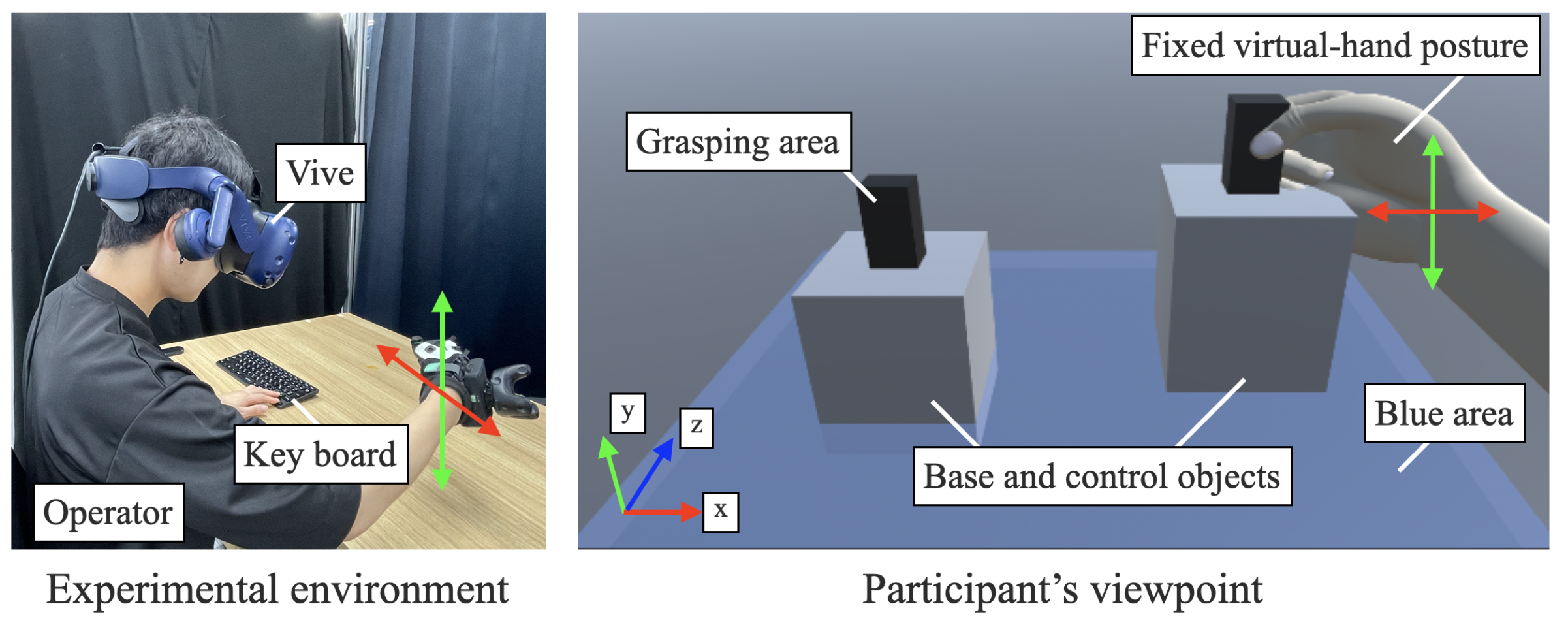
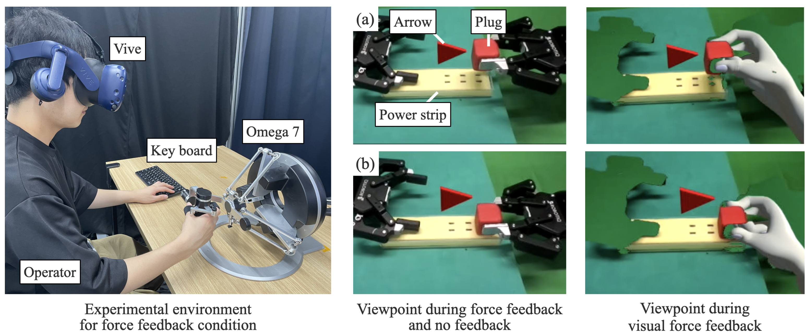
4.2.2. Experimental Setup

The distance between the two objects was 40 cm, and they were identical in terms of appearance and size. Objects could be lifted by grasping a black bar with the thumb and index fingers. The width of the black bar was 3.5 cm. When the actual fingers were closed off, the distance between the tips of the virtual thumb and index finger was the same as that of the black bar, providing the appearance of grasping the bar. When lifting an object, the posture of the virtual hand was fixed because the virtual hand postures of different people would change the appearance of the deformation of the virtual fingers. Additionally, the position in the z-axis direction was fixed to easily grasp the black bar, and the virtual hand was manipulated to two degrees of freedom. When the operator released the object, it immediately returned to its initial position. The offset of the base object ranged from 0 to 35 mm, and that of the control object ranged from 5 to 40 mm. The offsets of the base and control objects never matched.

4.2.3. Procedure

The participants were instructed to lift the object while looking at the virtual hand and the object. They were not informed of how to detect differences in weight. Participants lifted two objects above the blue area (5 cm above the ground) and judged the heavier object. The participants could lift the objects as many times as they wished. The speed of lifting was not specified. If the participant answered correctly (heavier object), the weight of the base object was changed randomly. The weight of the control object was one level higher than that of the base object. The positions of the two objects were then swapped randomly between the left and right sides. If the participants answered incorrectly, that is, if they selected the lighter object or answered that both objects weighed the same, the weight of the base object did not change, and the weight of the control object was increased in one step. The positions of the two objects were then randomly swapped between the left and right sides. If the offset was 40 mm when the control object was lifted, the weight of the base object was randomly changed, even if the answer was incorrect, and the control object was made one level heavier than the base object. The participants repeated each weight (offsets of 0, 5, 10, 15, 20, 25, 30, and 35 mm) of the base object 10 times under the two conditions of conventional pseudo-haptic and virtual finger deformations (at least 2 × 8 × 10 = 160 times).
After the weight comparison experiment, the participants lifted an object of each weight and answered the question, “How much weight do you feel in your hand?” on a seven-point Likert scale (from −3 = do not feel weight to 3 = strongly feel weight). The weights were then randomly changed.

4.3. Static Analysis
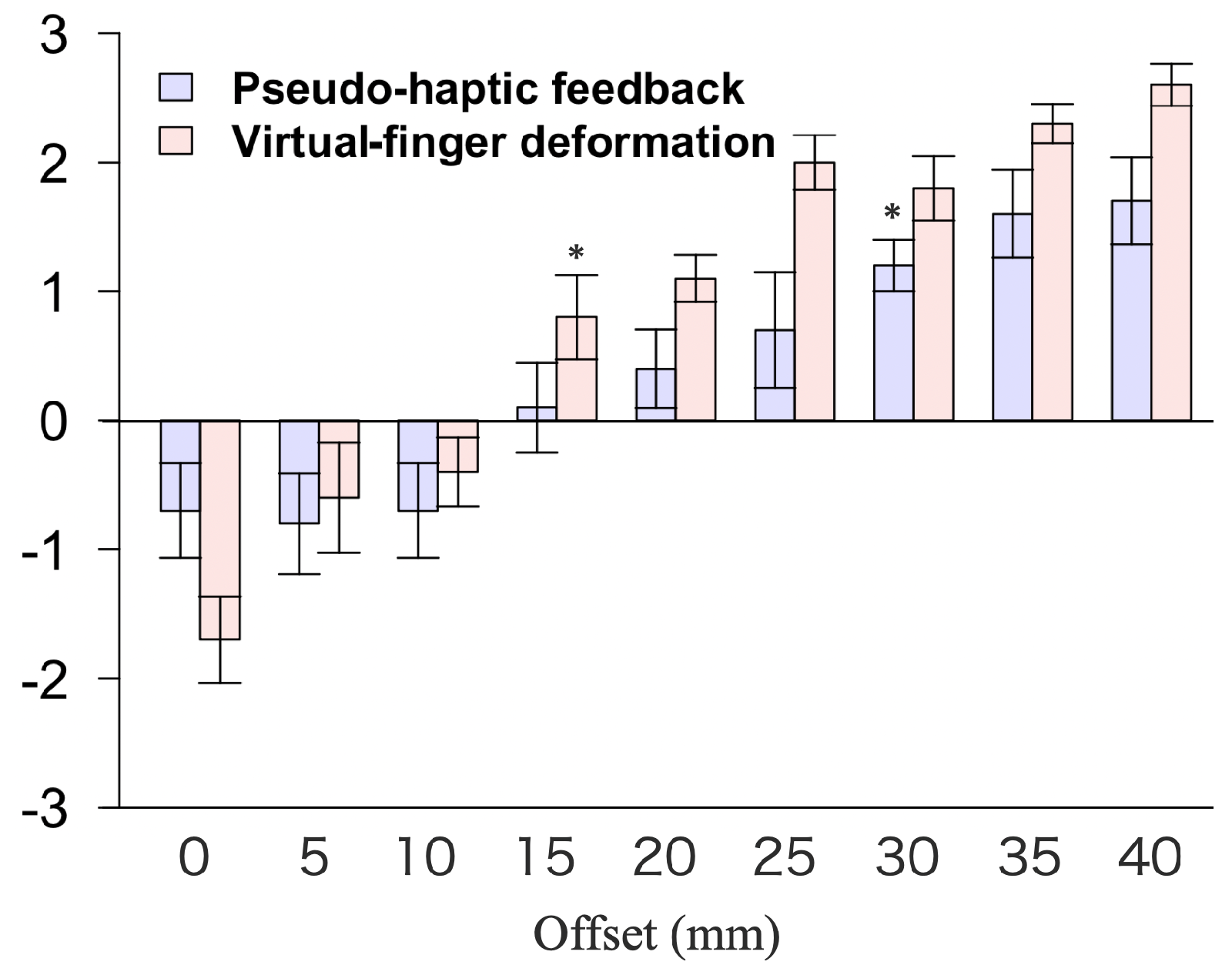
The success rate of the weight comparison between each base object and control object was averaged for each participant and calculated. To evaluate the proposed method, success rates were compared under two conditions: conventional pseudo-haptic feedback and virtual finger deformation. If a score of zero or less was recorded in the questionnaire results, it was considered as not feeling the weight in the hand. The average of the participants’ questionnaire results was calculated, and the offset at which they began to feel the weight in their hands was determined by whether it was significantly greater than zero.

4.4. Results

Figure 8 shows the correct answer rates for where the participants accurately recognized the heavier weight by comparing the weights of the base and control objects. In addition, Figure 9 shows the results for the question, “How much weight do you feel in your hand?” on a seven-point Likert scale (from −3 = do not feel weight to 3 = strongly feel weight). The blue bars show the results with pseudo-haptic feedback, and the red bars show the results with virtual finger deformation. Error bars show the standard error.
As shown in Figure 8, the results of the Wilcoxon signed-rank sum test between pseudo-haptic feedback and virtual finger deformation show that the latter had a significantly higher correct answer rate than the former when the base and control object offsets were 5 and 10 mm, respectively (base offset, 5 mm, control offset, 10 mm: z(9) = −2.46, p = 0.014). In addition, the virtual finger deformation had a significantly higher correct answer rate than the pseudo-haptic feedback when the base object offset was 10 mm and the control object offset was 15 mm (base offset, 10 mm; control offset, 15 mm: z(9) = −2.11; p = 0.035). Virtual finger deformation had a significantly higher correct answer rate than pseudo-haptic feedback when the base object offset was 15 mm and the control object offset was 20 and 25 mm (base offset, 15 mm; control offset, 20 mm: z(9) = −2.69; p = 0.007; base offset, 15 mm; control offset, 25 mm: z(9) = −2.21; p = 0.027). The virtual finger deformation had a significantly higher correct answer rate than the pseudo-haptic feedback when the base and control object offsets were 30 and 40 mm, respectively (base offset, 30 mm; control offset, 40 mm: z(9) = −2.23; p = 0.026).
As shown in Figure 9, the Wilcoxon signed-rank sum test results between the questionnaire results for each offset in the pseudo-haptic feedback and zero were significantly greater than zero when the offset was 30 mm or greater (offset 30 mm: z(9) = 2.76, p = 0.006). Moreover, the results of the Wilcoxon signed-rank sum test between the questionnaire results for each offset in the virtual finger deformation and zero were significantly greater than zero when the offset was 15 mm or greater (offset, 15 mm: z(9) = 2.11, p = 0.035, p = 0.035).

4.5. Discussion

The purpose of Experiment 1 was to compare the accuracy of recognizing different weights using virtual finger deformation compared to using pseudo-haptic feedback. In addition, the extent of virtual finger deformation required to perceive weight was investigated. As shown in Figure 8, the correct answer rate was higher for virtual finger deformation than for the pseudo-haptic feedback in most cases. In addition, weight comparisons of the base objects with offsets of 5, 10, and 15 mm and the weights for each control offset showed that the virtual hand accurately detected significantly different offsets of 5 and 10 mm, unlike the pseudo-haptic feedback. This is because the visual information used to compare the weights was increased by virtual finger deformation. Furthermore, the participants recognized the difference in weight by observing the amount of deformation of the virtual fingers, regardless of the speed at which they lifted the object. In this study, the weight was varied by varying the offset value. The larger the offset, the longer the slow movement time of the virtual hand, and the heavier the operator. Therefore, pseudo-haptic feedback did not accurately detect differences in weight, unless the lifting speed was constant. When the difference in offset was small, recognizing the difference in the offset was difficult. By contrast, virtual finger deformation enabled the accurate recognition of differences in weight through the amount of deformation of the virtual fingers, regardless of the lifting speed. Thus, a significantly higher rate of correct answers was considered in the virtual finger deformation condition when the difference in weight was small.
When the base object offset was 30 mm and the control object offset was 40 mm, the virtual finger deformation was significantly more accurate than the pseudo-haptic feedback. However, when the weights with base object offsets of 0, 20, 25, 30, and 35 mm and each control object offset were compared, there was no significant difference between the pseudo-haptic feedback and virtual finger deformation. This is because when the base offset is small, it is easy to notice the difference in the weights. However, when the base offset is large, it is difficult to observe differences in weights. According to Weber–Fechner’s law, psychological perception (weight) is nonlinear, even if the stimulus strength (offset) varies linearly [32]. Thus, even when the base offset was 0 mm and the difference in the offset was small (5 and 10 mm), the difference in weight was easily recognized under both the pseudo-haptic feedback and virtual finger deformation conditions, and there was no significant difference in the success rate. In addition, when the base offsets were 20, 25, 30, or 35 mm and the difference in offset was 5 mm, it was difficult to recognize the difference in weight for both the pseudo-haptic feedback and virtual finger deformation conditions, and there was no significant difference in the correct answer rate.
The results of the questionnaire on whether the participants felt the weight in their own hand showed that in conventional pseudo-haptic feedback, the participants began to feel the weight when the offset was 30 mm. In contrast, the participants began to feel the weight when the offset was 15 mm, owing to the virtual finger deformation. Thus, the virtual finger deformation allowed the participants to feel the weight at an offset of 15 mm less than the pseudo-haptic feedback. When participants were interviewed about virtual finger deformation after the experiment, seven out of ten participants said that they felt as if their fingers were actually bent. Therefore, the participants felt that they could easily perceive the weight because of the illusion that their fingers were bent. However, when the virtual fingers were bent by as much as 40 mm, a few participants felt discomfort and felt that their fingers were not bent. When they perceived that the virtual hand was different from their own hand, their sense of ownership of the virtual hand decreased, and they felt that their own hand was not deformed. Therefore, it is necessary to investigate the acceptable extent of finger deformation in terms of sense of ownership and perceived weight. In addition, some participants responded that finger bending corresponded to lifting a heavy object. It is believed that the bending of their fingers gave them an image of the weight, which made them feel the weight more easily.
In teleoperation, a large gap between the position of the operator’s hand and that of the robotic hand (offset) reduces operability and causes discomfort. Virtual finger deformation can cause the operator to feel weight while reducing the offset from the conventional pseudo-haptic feedback. Thus, virtual finger deformation is considered a very effective method for making the operator feel weight visually during teleoperation.

5. Experiment 2—Touch-and-Plugging Judgment Experiment

Experiment 2 was conducted to confirm whether touch and force can be intuitively recognized by virtual finger deformation. Three conditions were compared: no feedback, visual force feedback from the virtual finger deformation, and force feedback using a force-feedback device.

5.1. Experimental Condition

5.1.1. Task Design

The experimental environment was designed for plugging into a power strip. In the plugging task, the tip of the plug is often obscured by the hand or the power strip, making it difficult to confirm whether the plug is in contact with or fully inserted into the power strip without force feedback. Therefore, the plugging task was conducted to determine force-feedback influence on the recognition of touch and the magnitude of force applied.

5.1.2. Experimental Setup

The experimental environment for the no-feedback and visual-force-feedback conditions is shown in Figure 6, and the experimental environment for the force-feedback condition and the operator’s perspective is shown in Figure 10. The width of the plug was 3.5 cm. The UR on the left side was positioned to hold the power strip such that the plug could be removed using the right hand. The operator’s head was positioned such that the touch point between the plug and power strip was not visible. Rendering the touch point invisible prevented the recognition of touch and force, regardless of force feedback. The posture of the robotic hand was fixed, and the participants could manipulate the robotic hand with only one degree of freedom in a direction perpendicular to the power strip. An Omega 7 haptic device with seven DOFs (six DOFs plus a gripper) was used to return the force directly to the participants, as shown in Figure 10. The force values were obtained using the force sensor integrated into the UR5e, and a damping factor was included to stabilize the force feedback. The maximum force feedback was 4 N.

5.1.3. Procedure

The participants manipulated the robotic hand using their right hand to pull the plug out of the power strip and raise it to the height of the arrow (6 cm above the power strip) displayed on the HMD. In the touch judgment experiment, the researcher shifted the power strip so that the plug did not align with the hole in the power strip when lowered. In the plugging judgment experiment, the experimenter adjusted the position of the power strip such that the plug aligned with the hole in the power strip when the plug was lowered. To ensure that the speed of inserting the plug into the power tap was consistent across participants, they practiced for 5 min to operate the plug at the same speed (3.0 cm/s) as the arrow moving toward the power tap at a constant speed displayed on the HMD. The operators lowered the plug and pressed the “Enter” key with their left hand the moment they felt that the plug had made contact with the power tap (inserted deeply into the tap). Participants repeated the three conditions (no feedback, visual force feedback, and force feedback) ten times each in two experiments (touch-and-plugging judgment tasks) for a total of 60 trials ( 3 × 2 × 10 = 60 ). To confirm whether the participants were able to intuitively recognize the touch, the time required to recognize that the plug touched the power strip was measured. Additionally, to confirm whether the participants could intuitively recognize that the force necessary to insert the plug was applied, the time required to recognize that the plug was inserted deeply into the power strip was measured.

5.2. Statistical Analyses
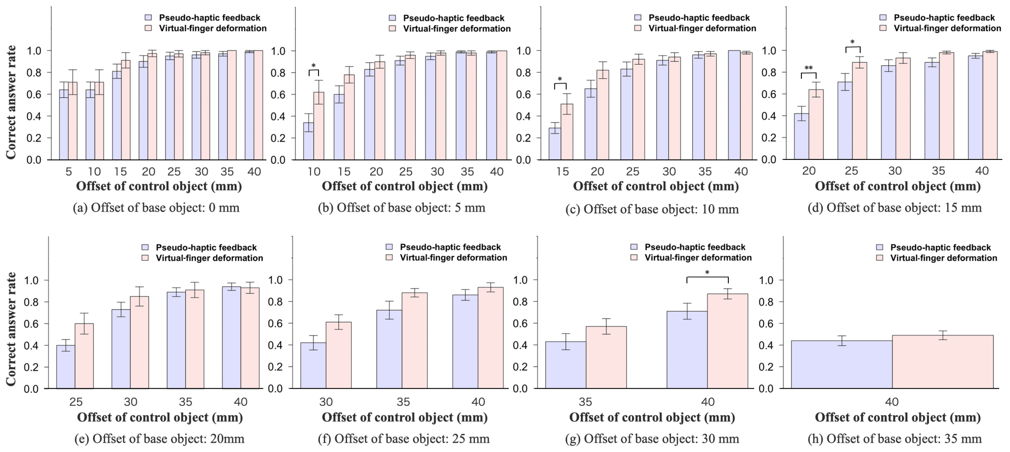
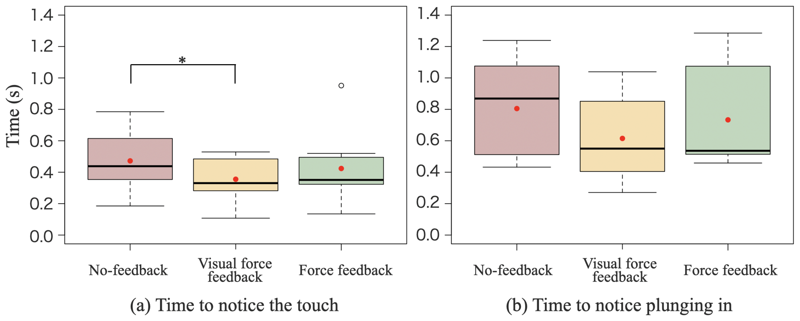
The time between Unity acquiring the value of the force applied to the robotic hand and the participant pressing the “Enter” key was recorded. The data used for each participant were the average of the values acquired over ten trials. Additionally, the time taken for Unity to acquire the force and for the video of the plug touching the power strip to reach the participant was less than 4.2 ms. Furthermore, the time taken for Unity to acquire and send the force to Omega was less than 10 ms. The same ten participants from Experiment 1 were used, with data obtained from nine. One participant was excluded because they performed the experiment using a visible touch point.

5.3. Results

Figure 11a shows the time taken to recognize that the plug touched the power strip under three conditions: no feedback, visual force feedback, and force feedback. Figure 11b shows the time required to recognize that the plug was inserted deeply into the power strip under each condition. The red boxes indicate the results under the no-feedback condition, the yellow boxes indicate the results for the visual-force-feedback condition, and the green boxes indicate the results for the force-feedback condition.
As shown in Figure 11a, the results of the touch judgment experiment indicate that contact was recognized 24.7 % faster with visual force feedback than with no feedback, and 24.2 % faster with force feedback than with no feedback. In addition, the Bonferroni correction among the three conditions revealed that the time required to recognize the touch was significantly shorter for visual force feedback than for no feedback (no feedback vs. visual force feedback: p = 0.037). No significant differences were observed between the other conditions (no feedback vs. force feedback, p = 0.63; visual force feedback vs. force feedback, p = 0.63).
As shown in Figure 11b, the results of the insertion judgment experiment showed that the time required to recognize that the plug was inserted was 23.6% shorter with visual force feedback than with no feedback, and 8.92% shorter with force feedback than with no feedback. Furthermore, Bonferroni correction among the three conditions showed that no significant differences were found among the three conditions (no feedback vs. visual force feedback: p = 0.18; no feedback vs. force feedback: p = 1.00; visual force feedback vs. force feedback: p = 0.30).

5.4. Discussion

The purpose of Experiment 2 was to determine whether contact and force could be recognized intuitively through virtual hand deformation. The results of the touch judgment experiment show that the time taken to judge touch was significantly shorter in the visual-force-feedback condition than in the no-feedback condition. There was no significant difference between the force feedback and visual-force-feedback conditions. Therefore, the results confirm that virtual finger deformation enabled the recognition of touch as fast as, or faster than, when a force device was used. A prior study reported that the response speed to visual stimuli was slower than tactile stimuli [33]. However, the results of this experiment show that the reaction speeds to visual stimuli from the deformation of the virtual finger and the force presentation by force feedback were similar. The results suggest that the reaction time from virtual finger deformation was similar to that from the tactile stimulus due to the illusion of actual tactile sensation in the hand caused by virtual finger deformation. Some participants in Experiment 1 also felt that their fingers were bent, suggesting that they experienced tactile sensations owing to the virtual finger deformation. However, the reaction speed to stimulation by force presentation may have been slower than to tactile stimulation. Thus, it is necessary to confirm the importance of virtual finger deformation by investigating the reaction speed when the virtual finger of another person is bent. Additionally, it is necessary to investigate whether the reaction speed for force presentation is slower than for tactile presentation.
The results of the plugging judgment experiment show that the time required to judge plugging tended to be shorter when the virtual finger was deformed than when there was no feedback. However, no significant differences were observed among these conditions. This is because, unlike the case of touch judgment, the criteria for judging whether a plug was inserted differed for each participant. Participants judged touch based on the deformation of their virtual fingers or the perception of force in their hands. However, when judging plugging by virtual finger deformation, some participants continued to lower their hands even after the maximum deformation of the virtual finger and only judged that they could plug in when they felt that the virtual finger would not deform any further. Other participants felt that they could plug in when the virtual finger was deformed. Similarly, in the force-feedback condition, some participants felt that they could insert the plug the moment they felt the force, whereas others felt they could insert the plug after confirming that the force had returned. Therefore, visual or direct force feedback did not produce a significant difference compared with the no-feedback condition. The behavior of participants who continued to lower their hands after the maximum deformation of the virtual fingers indicated that they were unable to recognize the degree of force required to insert the plug based on the virtual finger deformation. Therefore, it is necessary to increase the amount of information that informs the operator when the virtual finger deformation has reached its maximum value. For example, when the virtual finger is deformed to the maximum, methods such as changing the color of the virtual finger or vibrating it can be used.

6. Conclusions and Discussion

6.1. Conclusions

This study confirmed that visual force feedback via virtual hand deformation enhances the accuracy of force perception and the transparency of teleoperation when compared to conventional pseudo-haptic feedback. Furthermore, this method proved to be as effective as physical force-feedback devices. The interface displays virtual hands superimposed over the robot’s hands in camera images and deforms these virtual hands in response to the force applied to the robot, creating the illusion of operator’s hand deformation.
The weight comparison experiment demonstrated that small weight differences were significantly more discernible with virtual finger deformations than with pseudo-haptic feedback. It was also observed that participants perceived weight with an offset as small as 15 mm, which is 15 mm less than that required by conventional pseudo-haptic feedback. The touch-and-plugging judgment experiments showed that contact was detected significantly faster with virtual hand deformation compared to no feedback, and nearly as quickly as with a force-feedback device. However, no significant difference was noted in the speed of detecting that a plug was inserted between the no-feedback condition and the virtual hand deformation condition.
These findings indicate that the proposed interface enhances the transparency of teleoperation by minimizing the spatial mismatch between the robot’s and operator’s hands for force detection. Moreover, the interface addresses the challenge of contact judgment faced by conventional pseudo-haptic feedback, providing the operator with greater force sensitivity. However, additional improvements are needed to facilitate intuitive force recognition, as the current interface did not effectively convey the force needed to insert a plug. By addressing this limitation, the proposed interface could significantly improve visual force detection during teleoperation, making it a highly effective tool.

6.2. Discussion

Three key issues have been identified in conventional pseudo-tactile feedback, which the proposed method aims to address. First, the transparency of teleoperation is typically compromised by the displacement (offset) between the operator’s and the robot’s hands, which is necessary to generate pseudo-haptic feedback. The proposed method minimizes this offset, especially during larger movements, maintaining transparency. Although our method also involves an offset, perceiving the operator’s hand as deformed effectively eliminates this offset, potentially preserving the transparency of teleoperation. This aspect of the interface could be further analyzed by assessing whether operators maintain a sense of proprioception at the deformed virtual fingertip. Second, conventional methods often delay the detection of contact. The proposed method facilitates the recognition of contact as swiftly as a force-feedback device. Previous research indicates that tactile sensations are generally quicker than visual responses in reacting to force. Therefore, the effectiveness of the proposed interface can be better understood by identifying the mechanism leading to faster contact perception. Third, intuitively recognizing force remains challenging. Our method enhances force sensitivity beyond that of conventional pseudo-haptic feedback, allowing for more precise force adjustments. However, accurately assessing the force necessary to engage actions such as plugging in a plug remains problematic. Developing a system to calibrate the virtual hand’s deformation for each operator could improve the accuracy of force magnitude recognition. Overall, this interface offers enhanced transparency in teleoperation and greater force sensitivity compared to traditional pseudo-haptic feedback, achieving performance on par with force-feedback devices. Therefore, the interface significantly enhances teleoperation task performance without physical constraints, warranting further research into its development and refinement.

6.2.1. Applications of This Interface

The proposed interface enhances the operability of tasks that require force sensation. In this study, the task of inserting a plug was assumed. Without force sensation, the operator cannot detect whether the plug has made contact with the power strip. Additionally, there is no sensation of the plug being inserted into the hole of the power strip, making it difficult for the operator to determine whether the plug has been fully inserted, which requires additional time for confirmation and reduces work efficiency. Therefore, this interface can improve work efficiency by providing force sensation. Furthermore, it improves the quality of the teleoperation experience by presenting force sensation. Thus, this interface contributes to the development of teleoperation robots by enhancing their operability and supporting social participation.

6.2.2. Future Works

A limitation of this interface is that if the robotic hand is not visible to the camera, it is difficult to visually present the force sensation. If the robotic hand is hidden by a wall or other objects, a force sensation can be conveyed by displaying a silhouette of the virtual hand on the wall or other surfaces. However, if the robotic hand is outside the camera’s field of view, the force sensation cannot be visually presented. Therefore, it is necessary to investigate methods for presenting virtual hand deformation, even when the robotic hand is outside the camera’s field of view.
We believe that equipping the follower robot with a tactile sensor would significantly enhance the force-feedback capabilities of the interface in two key ways. First, tactile sensors enable the detection of slippage in a grasped object, allowing for the implementation of a system that alerts the operator to changes in force when the grasp slips. By visually signaling shifts in the position of the grasped object due to slippage or external forces, operators can manipulate objects with greater sensitivity. This capability ensures that operators can perceive slippage as a tangible force, preventing the object from slipping further and enabling the adjustment of gripping force to the minimum necessary to lift soft objects without crushing them. Second, the integration of tactile sensors permits the robot to ascertain the shape of the object it grasps. This functionality allows for the deformation of the virtual finger to accurately mirror the shape of the grasped object. For instance, without tactile sensing, when grasping a conical object, the virtual representation might inaccurately depict the finger as either buried in or detached from the object. Tactile sensors rectify this issue by providing precise shape data, facilitating more realistic and accurate representations of the virtual fingers.
In this study, force in one direction was demonstrated using virtual finger deformation. Therefore, methods are required to present forces in additional directions when interacting with objects using this virtual deformation technique. Moreover, the virtual fingers in this study were deformed by picking up an object with only two fingers. It is necessary to explore methods that allow the virtual hand to convey an intuitive feel of the force sensation in the operator’s hand for different grasping methods. For example, it is necessary to consider whether the amount of deformation should be reduced when grasping an object with three or more fingers compared to two, or whether it would be beneficial to deform not only the fingers but also the wrist when the operator grips a large object. By further investigating these methods, the limitations of virtual finger deformation can be addressed.

Author Contributions

Conceptualization, K.Y. and Y.H.; methodology, K.Y.; software, K.Y.; validation, Y.Z.; formal analysis, K.Y.; investigation, K.Y.; resources, Y.H.; data curation, K.Y.; writing—original draft preparation, K.Y.; writing—review and editing, K.Y., Y.Z. and Y.H.; visualization, K.Y.; supervision, Y.Z., T.A. and Y.H.; project administration, Y.H.; funding acquisition, Y.H. All authors have read and agreed to the published version of the manuscript.

Funding

This work was supported in part by JST SICORP, Japan, under Grant JPMJSC2305.

Institutional Review Board Statement

All ethical and experimental procedures and protocols were approved by the Ethics Review Committee of Nagoya University under Application No. 23-9 and performed in line with the Declaration of Helsinki.

Informed Consent Statement

Informed consent was obtained from all the subjects involved in the study.

Data Availability Statement

The original contributions presented in the study are included in the article, further inquiries can be directed to the corresponding author.

Conflicts of Interest

The authors declare no conflicts of interest.

Abbreviations

The following abbreviations are used in this manuscript:
VRVirtual reality;
C/D ratioControl-to-display ratio;
ROSRobot operating system.

References

  1. Sheridan, T.B. Telerobotics, Automation, and Human Supervisory Control; MIT Press: Cambridge, MA, USA, 1992. [Google Scholar]
  2. Yoon, W.K.; Goshozono, T.; Kawabe, H.; Kinami, M.; Tsumaki, Y.; Uchiyama, M.; Oda, M.; Doi, T. Model-based space robot teleoperation of ETS-VII manipulator. IEEE Trans. Robot. Autom. 2004, 20, 602–612. [Google Scholar] [CrossRef]
  3. Guo, Y.; Freer, D.; Deligianni, F.; Yang, G.Z. Eye-tracking for performance evaluation and workload estimation in space telerobotic training. IEEE Trans. Hum.-Mach. Syst. 2021, 52, 1–11. [Google Scholar] [CrossRef]
  4. Roquet, P. Telepresence enclosure: VR, remote work, and the privatization of presence in a shrinking Japan. Media Theory 2020, 4, 33–62. [Google Scholar]
  5. Martins, H.; Oakley, I.; Ventura, R. Design and evaluation of a head-mounted display for immersive 3D teleoperation of field robots. Robotica 2015, 33, 2166–2185. [Google Scholar] [CrossRef]
  6. Kot, T.; Novák, P. Utilization of the Oculus Rift HMD in mobile robot teleoperation. Appl. Mech. Mater. 2014, 555, 199–208. [Google Scholar] [CrossRef]
  7. Zhu, Y.; Fusano, K.; Aoyama, T.; Hasegawa, Y. Intention-reflected predictive display for operability improvement of time-delayed teleoperation system. Robomech J. 2023, 10, 17. [Google Scholar] [CrossRef]
  8. Schwarz, M.; Lenz, C.; Memmesheimer, R.; Pätzold, B.; Rochow, A.; Schreiber, M.; Behnke, S. Robust immersive telepresence and mobile telemanipulation: Nimbro wins ana avatar xprize finals. In Proceedings of the 2023 IEEE-RAS 22nd International Conference on Humanoid Robots (Humanoids), Austin, TX, USA, 12–14 December 2023; IEEE: New York, NY, USA, 2023; pp. 1–8. [Google Scholar]
  9. Zhu, Y.; Jiang, B.; Chen, Q.; Aoyama, T.; Hasegawa, Y. A shared control framework for enhanced grasping performance in teleoperation. IEEE Access 2023, 11, 69204–69215. [Google Scholar] [CrossRef]
  10. Desbats, P.; Geffard, F.; Piolain, G.; Coudray, A. Force-feedback teleoperation of an industrial robot in a nuclear spent fuel reprocessing plant. Ind. Robot. Int. J. 2006, 33, 178–186. [Google Scholar] [CrossRef]
  11. Wildenbeest, J.G.; Abbink, D.A.; Heemskerk, C.J.; Van Der Helm, F.C.; Boessenkool, H. The impact of haptic feedback quality on the performance of teleoperated assembly tasks. IEEE Trans. Haptics 2012, 6, 242–252. [Google Scholar] [CrossRef]
  12. Selvaggio, M.; Cognetti, M.; Nikolaidis, S.; Ivaldi, S.; Siciliano, B. Autonomy in physical human-robot interaction: A brief survey. IEEE Robot. Autom. Lett. 2021, 6, 7989–7996. [Google Scholar] [CrossRef]
  13. Michel, Y.; Rahal, R.; Pacchierotti, C.; Giordano, P.R.; Lee, D. Bilateral teleoperation with adaptive impedance control for contact tasks. IEEE Robot. Autom. Lett. 2021, 6, 5429–5436. [Google Scholar] [CrossRef]
  14. Zhu, Q.; Du, J.; Shi, Y.; Wei, P. Neurobehavioral assessment of force feedback simulation in industrial robotic teleoperation. Autom. Constr. 2021, 126, 103674. [Google Scholar] [CrossRef]
  15. Abi-Farrajl, F.; Henze, B.; Werner, A.; Panzirsch, M.; Ott, C.; Roa, M.A. Humanoid teleoperation using task-relevant haptic feedback. In Proceedings of the 2018 IEEE/RSJ International Conference on Intelligent Robots and Systems (IROS), Madrid, Spain, 1–5 October 2018; IEEE: New York, NY, USA, 2018; pp. 5010–5017. [Google Scholar]
  16. Lécuyer, A.; Coquillart, S.; Kheddar, A.; Richard, P.; Coiffet, P. Pseudo-haptic feedback: Can isometric input devices simulate force feedback? In Proceedings of the IEEE Virtual Reality 2000 (Cat. No. 00CB37048), New Brunswick, NJ, USA, 18–22 March 2000; IEEE: New York, NY, USA, 2000; pp. 83–90. [Google Scholar]
  17. Dominjon, L.; Lécuyer, A.; Burkhardt, J.M.; Richard, P.; Richir, S. Influence of control/display ratio on the perception of mass of manipulated objects in virtual environments. In Proceedings of the IEEE Proceedings VR 2005, Virtual Reality, Bonn, Germany, 12–16 March 2005; IEEE: New York, NY, USA, 2005; pp. 19–25. [Google Scholar]
  18. Son, E.; Song, H.; Nam, S.; Kim, Y. Development of a Virtual Object Weight Recognition Algorithm Based on Pseudo-Haptics and the Development of Immersion Evaluation Technology. Electronics 2022, 11, 2274. [Google Scholar] [CrossRef]
  19. Lécuyer, A.; Burkhardt, J.M.; Etienne, L. Feeling bumps and holes without a haptic interface: The perception of pseudo-haptic textures. In Proceedings of the SIGCHI Conference on Human Factors in Computing Systems, Vienna, Austria, 24–29 April 2004; pp. 239–246. [Google Scholar]
  20. Rietzler, M.; Geiselhart, F.; Gugenheimer, J.; Rukzio, E. Breaking the tracking: Enabling weight perception using perceivable tracking offsets. In Proceedings of the 2018 CHI Conference on Human Factors in Computing Systems, Montreal, QC, Canada, 21–26 April 2018; pp. 1–12. [Google Scholar]
  21. Lawrence, D.A. Stability and transparency in bilateral teleoperation. IEEE Trans. Robot. Autom. 1993, 9, 624–637. [Google Scholar] [CrossRef]
  22. Almeida, L.; Menezes, P.; Dias, J. Interface transparency issues in teleoperation. Appl. Sci. 2020, 10, 6232. [Google Scholar] [CrossRef]
  23. Xavier, R.; Silva, J.L.; Ventura, R.; Jorge, J. Pseudo-Haptics Survey: Human-Computer Interaction in Extended Reality & Teleoperation. IEEE Access 2024, 12, 80442–80467. [Google Scholar]
  24. Jauregui, D.A.G.; Argelaguet, F.; Olivier, A.H.; Marchal, M.; Multon, F.; Lecuyer, A. Toward “pseudo-haptic avatars”: Modifying the visual animation of self-avatar can simulate the perception of weight lifting. IEEE Trans. Vis. Comput. Graph. 2014, 20, 654–661. [Google Scholar] [CrossRef]
  25. Samad, M.; Gatti, E.; Hermes, A.; Benko, H.; Parise, C. Pseudo-haptic weight: Changing the perceived weight of virtual objects by manipulating control-display ratio. In Proceedings of the 2019 CHI Conference on Human Factors in Computing Systems, Glasgow, UK, 4–9 May 2019; pp. 1–13. [Google Scholar]
  26. Kim, J.; Kim, S.; Lee, J. The effect of multisensory pseudo-haptic feedback on perception of virtual weight. IEEE Access 2022, 10, 5129–5140. [Google Scholar] [CrossRef]
  27. Botvinick, M.; Cohen, J. Rubber hands ‘feel’touch that eyes see. Nature 1998, 391, 756. [Google Scholar] [CrossRef]
  28. Haggard, P. Sense of agency in the human brain. Nat. Rev. Neurosci. 2017, 18, 196–207. [Google Scholar] [CrossRef]
  29. Sato, Y.; Hiraki, T.; Tanabe, N.; Matsukura, H.; Iwai, D.; Sato, K. Modifying texture perception with pseudo-haptic feedback for a projected virtual hand interface. IEEE Access 2020, 8, 120473–120488. [Google Scholar] [CrossRef]
  30. Rabellino, D.; Frewen, P.A.; McKinnon, M.C.; Lanius, R.A. Peripersonal space and bodily self-consciousness: Implications for psychological trauma-related disorders. Front. Neurosci. 2020, 14, 586605. [Google Scholar] [CrossRef] [PubMed]
  31. Yamamoto, K.; Zhu, Y.; Aoyama, T.; Takeuchi, M.; Hasegawa, Y. Improvement in the Manipulability of Remote Touch Screens Based on Peri-Personal Space Transfer. IEEE Access 2023, 11, 43962–43974. [Google Scholar] [CrossRef]
  32. Fechner, G.T. Elements of Psychophysics, 1860; Appleton-Century-Crofts: Norwalk, CT, USA, 1948. [Google Scholar]
  33. Ng, A.W.; Chan, A.H. Finger response times to visual, auditory and tactile modality stimuli. In Proceedings of the International Multiconference of Engineers and Computer Scientists, IMECS, Hong Kong, China, 14–16 March 2012; Volume 2, pp. 1449–1454. [Google Scholar]
Figure 1. Interface that presents pseudo-haptic feedback through deformation of virtual hands.
Robotics 13 00143 g001
Figure 2. Schematic of the teleoperation system utilized in this study, featuring an HMD (HTC VIVE Pro Eye) for immersive visual feedback, quantum metagloves for precise hand tracking, and universal robots (URs) for robotic manipulation. The system integrates visual feedback with hand tracking to enable real-time teleoperation within a robot operating system (ROS) environment.
Robotics 13 00143 g002
Figure 3. After the robotic hand is rendered transparent by chroma keying, the virtual hand is displayed according to the position and posture of the robotic hand.
Robotics 13 00143 g003
Figure 4. Offset of pseudo-haptic feedback and amount of fingertip movement by virtual hand deformation are equal. Index finger and thumb tips have robotic grippers.
Robotics 13 00143 g004
Figure 5. (a) Virtual finger deformation for comparison with the pseudo-haptic condition in Experiment 1. (b) Virtual finger deformation caused by the force applied to the gripper in Experiment 2. The second joint of the thumb and the third joint of the index finger rotate in the opposite direction of the applied force.
Robotics 13 00143 g005
Figure 6. Experimental environment and participant’s viewpoint for weight comparison experiment.
Robotics 13 00143 g006
Figure 7. Appearance of virtual finger deformation for each offset.
Robotics 13 00143 g007
Figure 8. (ah): Correct answer rates for where the participants accurately determined the heavier weight by comparing the weight of each base object and control object. The blue bars show the results with pseudo-haptic feedback, and the red bars show the results with virtual finger deformation. Error bars show the standard error. * p < 0.05, ** p < 0.01.
Robotics 13 00143 g008
Figure 9. The results of the question, “How much weight do you feel in your hand?” on a seven-point Likert scale (from −3 = do not feel weight to 3 = strongly feel weight) for each weight. Blue bars show the results with pseudo-haptic feedback, and red bars show the results with virtual finger deformation. Error bars show the standard error. * p < 0.05.
Robotics 13 00143 g009
Figure 10. Experimental environment for force feedback condition and operator’s viewpoints in the no-feedback, force-feedback, and visual-force-feedback conditions. (a) Participant lifting the plug to the height of the arrow before starting the experiment and after pressing the Enter key. (b) Participants move the plug closer to the power strip at a constant speed and press the Enter key when they feel the tip of the plug touching or being inserted into the power strip.
Robotics 13 00143 g010
Figure 11. (a) Time taken to recognize that the plug touched the power strip in each condition. (b) Time taken to recognize that the plug was stuck deep into the power strip under each condition. The red boxes indicate the results for the no-feedback condition. The yellow boxes show the results for the visual-force-feedback condition. The green boxes show the results for the force-feedback condition. The red dots show average values. * p < 0.05.
Robotics 13 00143 g011
Disclaimer/Publisher’s Note: The statements, opinions and data contained in all publications are solely those of the individual author(s) and contributor(s) and not of MDPI and/or the editor(s). MDPI and/or the editor(s) disclaim responsibility for any injury to people or property resulting from any ideas, methods, instructions or products referred to in the content.

