
Actuator Disk Model with Improved Tip Loss Correction for Hover and Forward Flight Rotor Analysis


Abstract
:1. Introduction
2. Methods
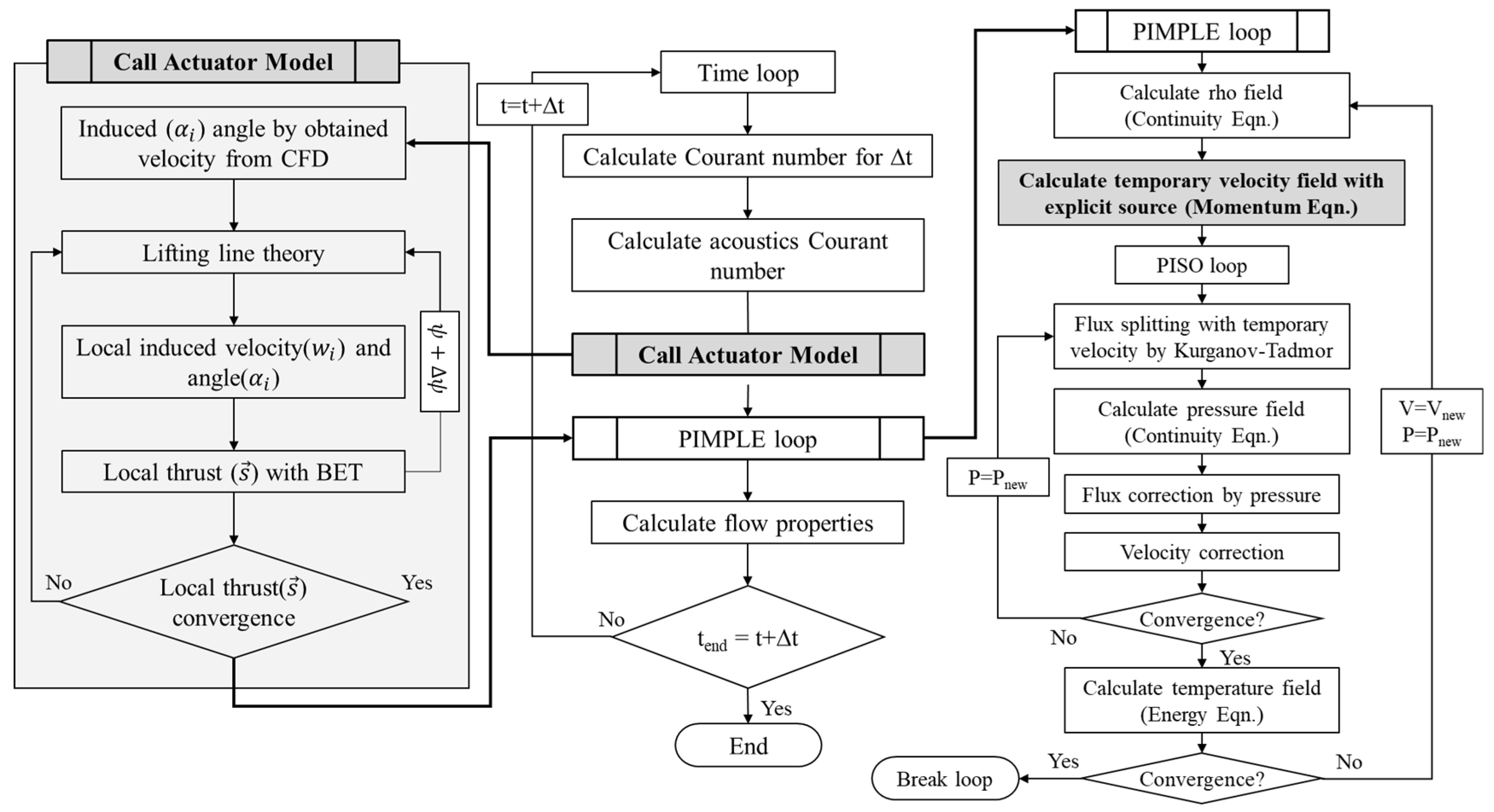
2.1. Structure of the Numerical Method
2.2. Actuator Model
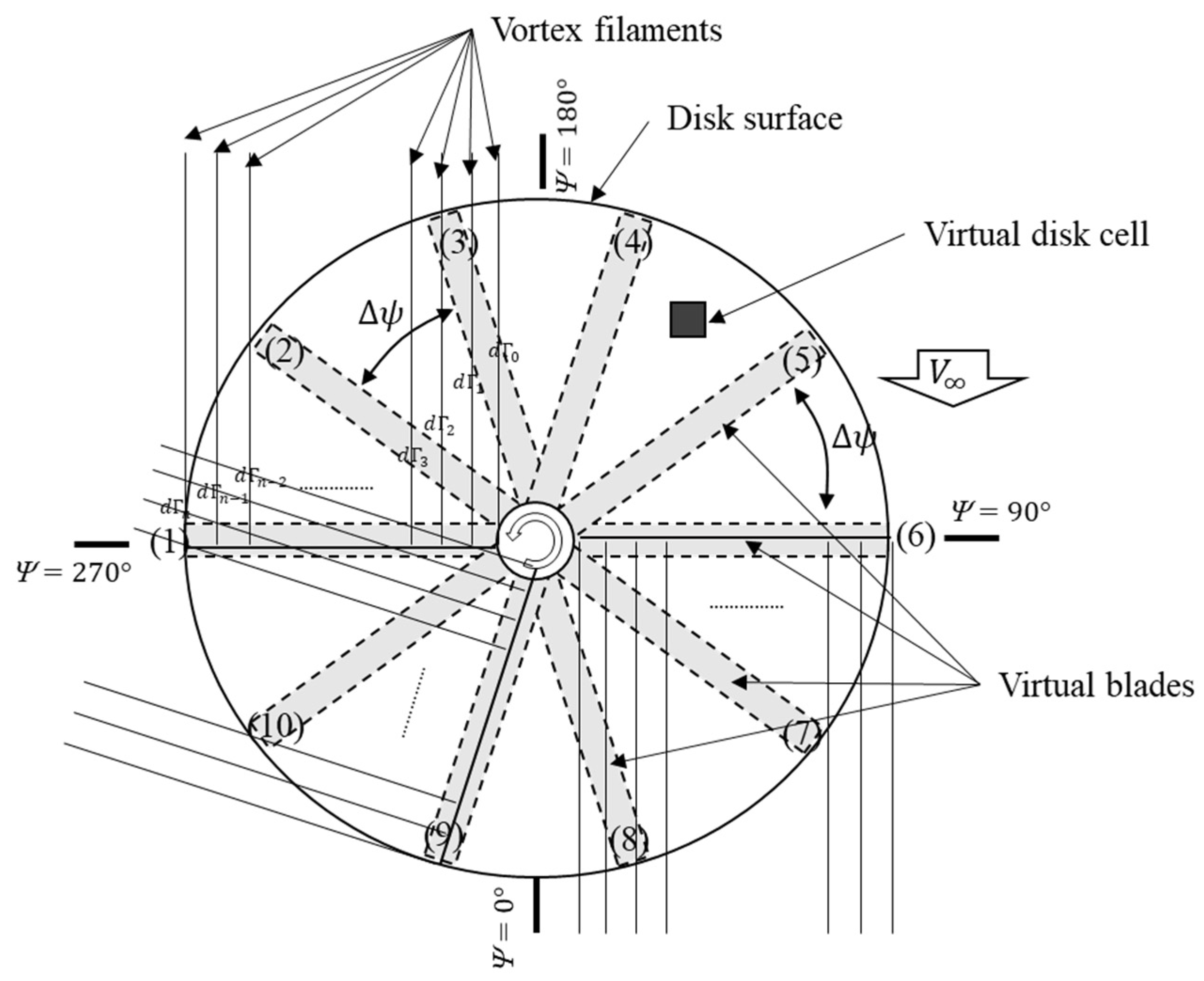
2.3. DADM
3. Results and Discussion
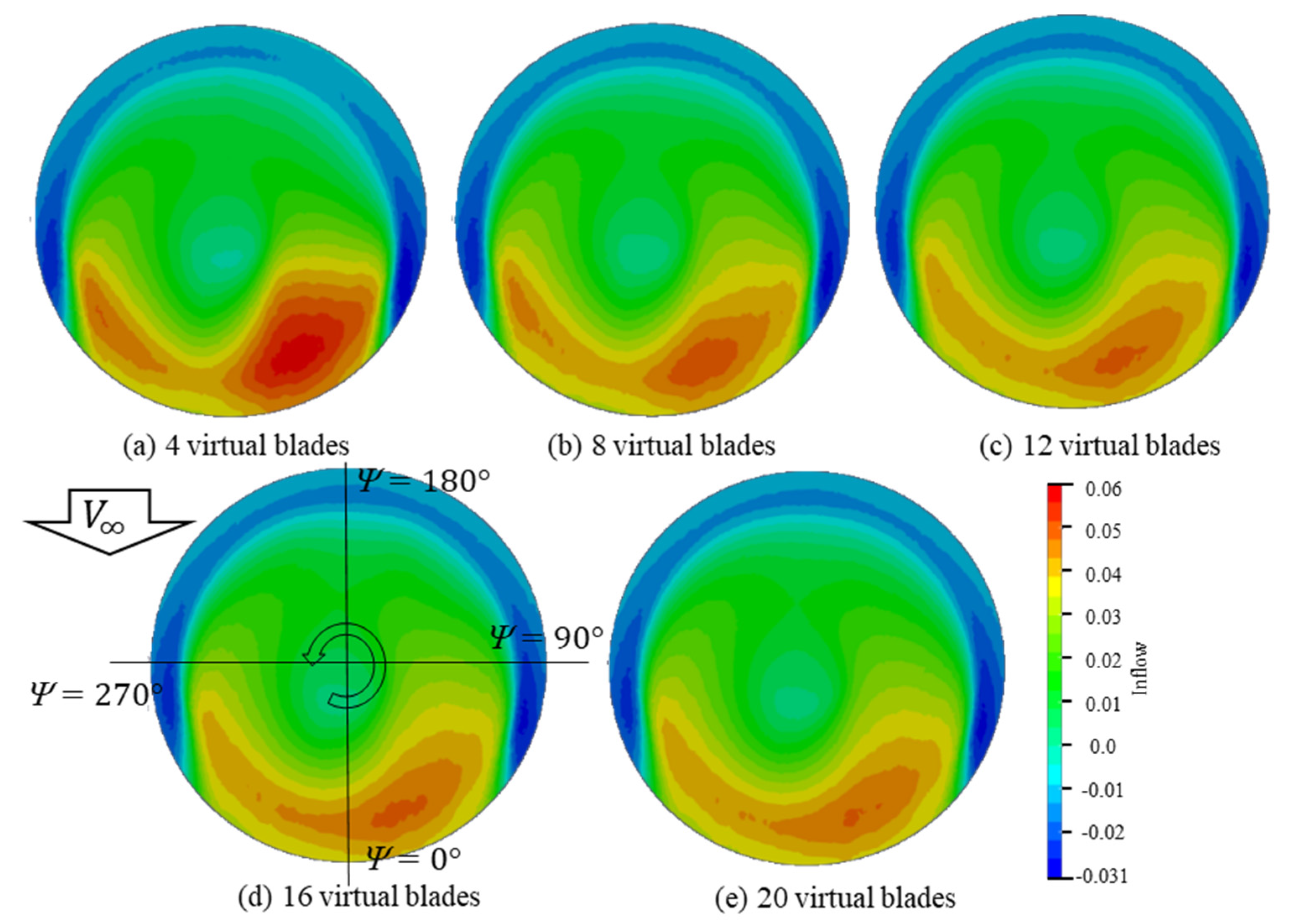
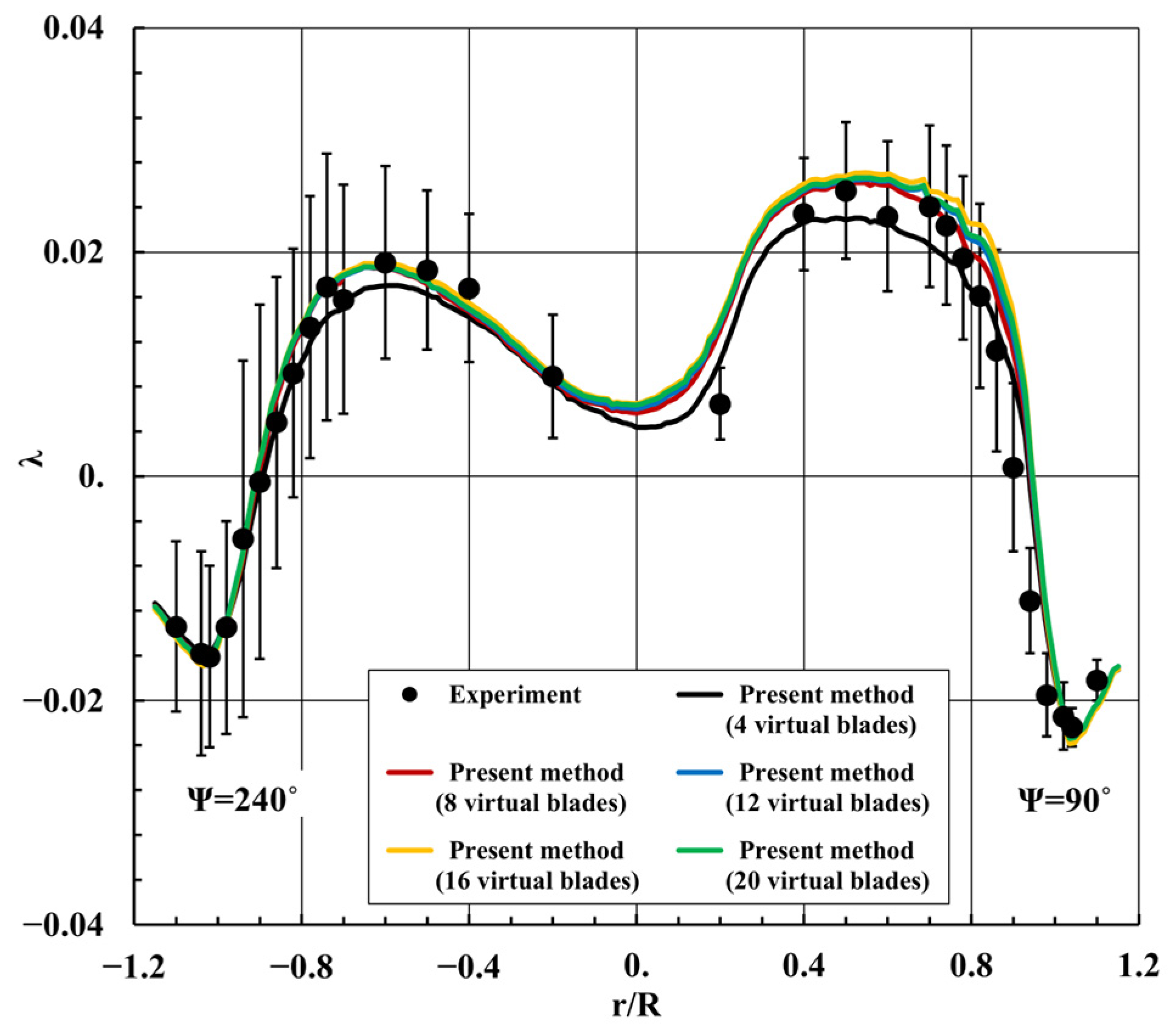
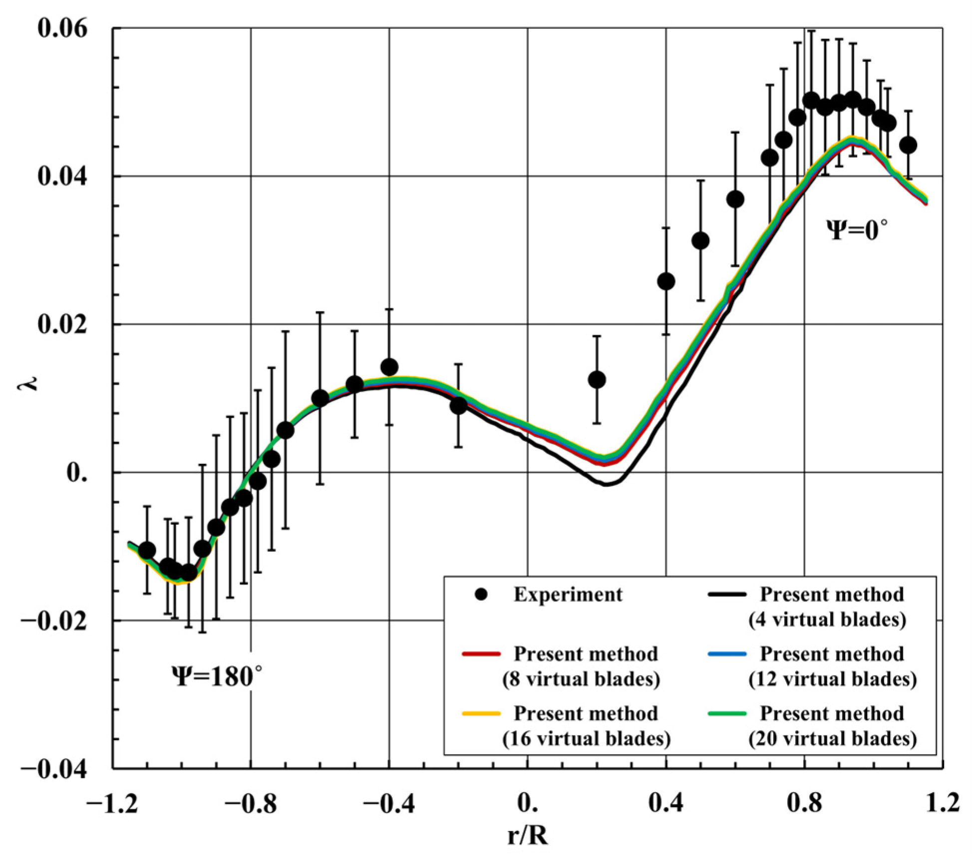
3.1. Number of Virtual Blades
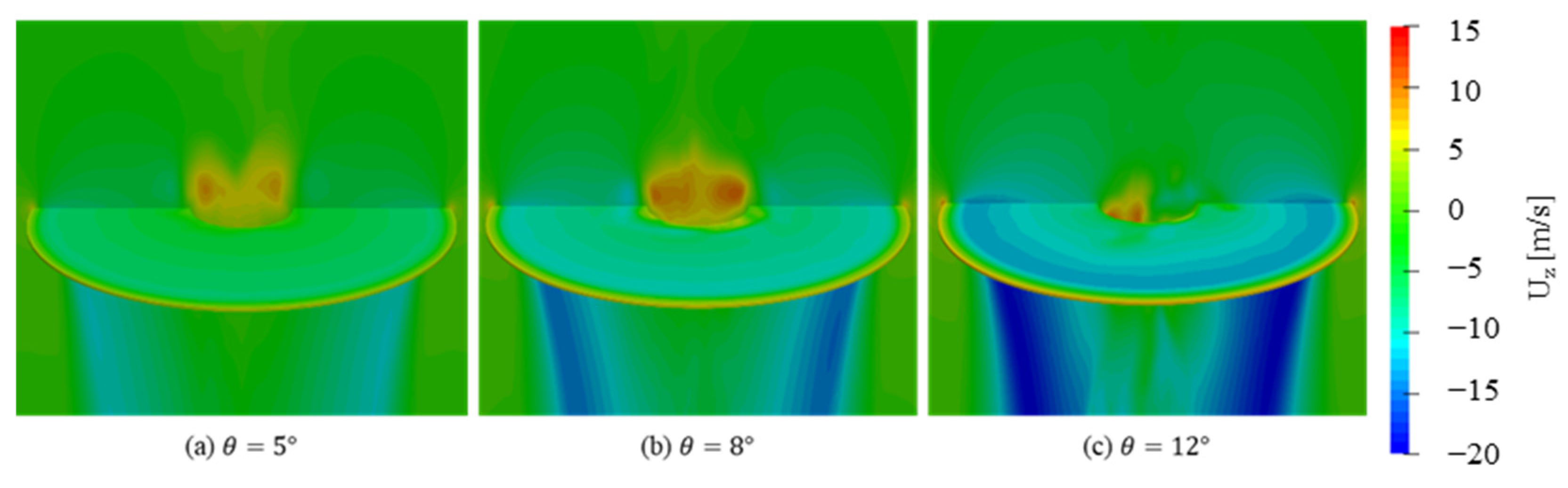
3.2. Hover Flight Rotor
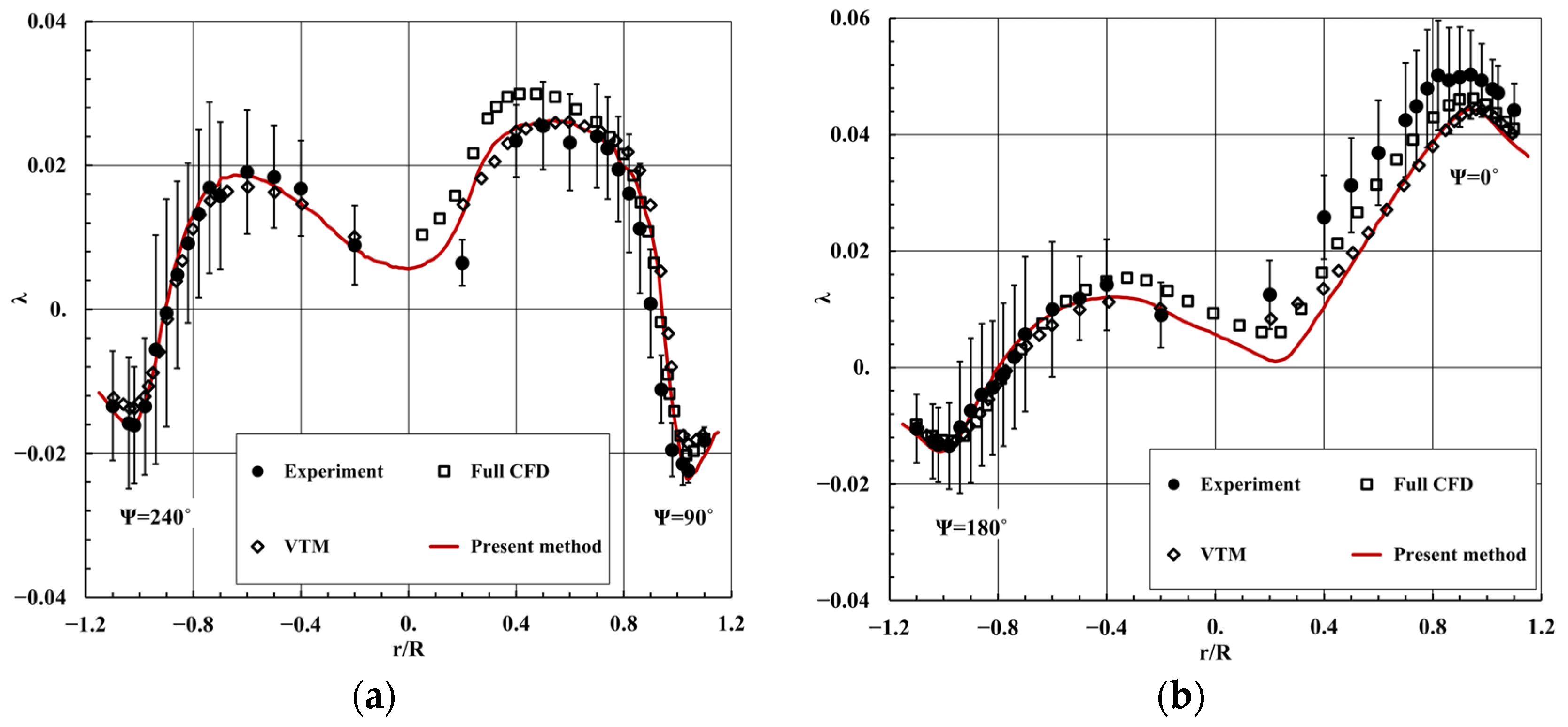
3.3. Forward Flight Rotor
4. Conclusions
- The DADM yielded good results for the blade tip region without the tip loss factor or function.
- The DADM has the ability to consider the spanwise normal force distribution based on the lifting-line theory.
Author Contributions
Funding
Data Availability Statement
Conflicts of Interest
References
- Perdolt, D.; Thiele, M.; Milz, D.; May, M.; Kuchar, R.; Hornung, M. Comparison of Multi-Fidelity Rotor Analysis Tools for Transitional and Low Speed Flight Regimes; Deutsche Gesellschaft für Luft- und Raumfahrt (DGLR): Gauting, Germany, 2021; pp. 1–13. [Google Scholar]
- Leishman, G.J. Principles of Helicopter Aerodynamics, 2nd ed.; Cambridge University Press: New York, NY, USA, 2006; Chapter 2. [Google Scholar]
- Boyd, D.D., Jr. Rotor/Fuselage Unsteady Interactional Aerodynamics: A New Computational Model. Ph.D. Thesis, Virginia Polytechnic Institute and State University, Blacksburg, VA, USA, 1999. [Google Scholar]
- Tadghighi, H. Simulation of rotor-body interactional aerodynamics: An unsteady rotor source distributed disk model. In Proceedings of the AHS International Annual Forum, 57th, Virginia Beach, VA, USA, 3–5 May 2011. [Google Scholar]
- O’Brien, D.M., Jr. Analysis of Computational Modeling Techniques for Complete Rotorcraft Configurations. Ph.D. Thesis, Georgia Institute of Technology, Atlanta, GA, USA, 2006. [Google Scholar]
- Sorensen, J.N.; Shen, W.Z. Numerical modeling of wind turbine wakes. J. Fluids Eng. 2002, 124, 393–399. [Google Scholar] [CrossRef]
- Troldborg, N. Actuator Line Modeling of Wind Turbine Wakes. Ph.D. Thesis, Technical University of Denmark, Lyngby, Denmark, 2009. [Google Scholar]
- Merabet, R.; Laurendeau, E. Actuator Line Method for Helicopter Rotors Computations in Various Flight Conditions. CASI Aero. Available online: https://www.semanticscholar.org/paper/Actuator-Line-Method-for-Helicopter-Rotors-in-Merabet-Laurendeau/a4079a552b9c1ecd3d28bc2a7a4499a40413236a (accessed on 23 March 2023).
- Dobrev, I.; Massouh, F.; Rapin, M. Actuator surface hybrid model. J. Phys. Conf. Ser. 2007, 75, 012019. [Google Scholar] [CrossRef]
- Kim, Y.H.; Park, S.O. Unsteady momentum source method for efficient simulation of rotor aerodynamics. J. Aircraft 2009, 50, 324–327. [Google Scholar] [CrossRef]
- Kim, T.; Oh, S.; Yee, K. Improved actuator surface method for wind turbine application. Renew. Energy 2015, 76, 16–26. [Google Scholar] [CrossRef]
- Kim, T.; Oh, S.; Yee, K. Novel actuator surface method for helicopter rotor analysis. J. Aircraft 2016, 53, 1947–1952. [Google Scholar] [CrossRef]
- Linton, D.; Barakos, G.; Widjaja, R.; Thornber, B. Coupling of an unsteady aerodynamics model with a computational fluid dynamics solver. AIAA J. 2018, 56, 3153–3166. [Google Scholar] [CrossRef]
- Roh, N.; Oh, S.; Park, D. Aerodynamic characteristics of helicopter with ducted fan tail rotor in hover under low-speed crosswind. Int. J. Aerosp. Eng. 2020, 2020, 7059209. [Google Scholar] [CrossRef]
- Kim, D.; Lee, Y.; Oh, S.; Park, Y.; Choi, J.; Park, D. Aerodynamic analysis and static stability analysis of Manned/unmanned distributed propulsion aircrafts using actuator methods. J. Wind Eng. Ind. Aerodyn. 2021, 214, 104648. [Google Scholar] [CrossRef]
- Sriti, M. Tip loss factor effects on aerodynamic performances of horizontal axis wind turbine. Energy Procedia 2017, 118, 136–140. [Google Scholar]
- Branlard, E.; Gaunaa, M. Development of new tip-loss corrections based on vortex theory and vortex methods. J. Phys. Conf. Ser. 2014, 555, 012012. [Google Scholar] [CrossRef]
- Zhong, W.; Wang, T.G.; Zhu, W.J.; Shen, W.Z. Evaluation of tip loss corrections to AD/NS simulations of wind turbine aerodynamic performance. Appl. Sci. 2019, 9, 4919. [Google Scholar] [CrossRef]
- Jasak, H. Error Analysis and Estimation for the Finite Volume Method with Applications to Fluid Flows. Ph.D. Thesis, Imperial College, London, UK, 1996. [Google Scholar]
- Ferziger, J.H.; Perić, M.; Street, R.L. Computational Methods for Fluid Dynamics, 3rd ed.; Springer: New York, NY, USA, 2012; pp. 196–200. [Google Scholar]
- OpenFOAM: API Guide. Available online: https://www.openfoam.com/documentation/guides/latest/doc/ (accessed on 1 May 2022).
- Kim, T.W.; Gill, J.H. Development of improved pressure-based solver algorithm for compressible flow. J. Comput. Fluids Eng. 2017, 22, 28–35. [Google Scholar] [CrossRef]
- Kraposhin, M.; Bovtrikova, A.; Strijhak, S. Adaptation of Kurganov-Tadmor numerical scheme for applying in combination with the PISO method in numerical simulation of flows in a wide range of Mach numbers. Procedia Comput. Sci. 2015, 66, 43–52. [Google Scholar] [CrossRef]
- Hoad, D.R.; Althoff, S.L.; Elliott, J.W.; Sailey, R.H. Inflow Measurement Made with a Laser Velocimeter on a Helicopter Model in Forward Flight; NASA-TM-100541; NASA Langley Research Center: Hampton, VA, USA, 1988. Available online: https://ntrs.nasa.gov/citations/19880015223 (accessed on 23 March 2023).
- Caradonna, F.X.; Tung, C. Experimental and Analytical Studies of a Model Helicopter Rotor in Hover; NASA-TM-81232; NASA Ames Research Center: Moffett Field, CA, USA, 1981. Available online: https://ntrs.nasa.gov/citations/19820004169 (accessed on 23 March 2023).
- Park, Y.M.; Nam, H.J.; Kwon, O.J. Simulation of unsteady rotor-fuselage interactions using unstructured adaptive meshes. Proceeding of the 59th Annual Forum of the American Helicopter Society, Phoenix, AZ, USA, 6–8 May 2003. [Google Scholar]
- Kenyon, A.R.; Brown, R.E. Wake dynamics and rotor-fuselage aerodynamic interactions. J. Am. Helicopter Soc. 2009, 54, 12003. [Google Scholar] [CrossRef]


Disclaimer/Publisher’s Note: The statements, opinions and data contained in all publications are solely those of the individual author(s) and contributor(s) and not of MDPI and/or the editor(s). MDPI and/or the editor(s) disclaim responsibility for any injury to people or property resulting from any ideas, methods, instructions or products referred to in the content. |
© 2023 by the authors. Licensee MDPI, Basel, Switzerland. This article is an open access article distributed under the terms and conditions of the Creative Commons Attribution (CC BY) license (https://creativecommons.org/licenses/by/4.0/).
Share and Cite
Son, C.; Kim, T. Actuator Disk Model with Improved Tip Loss Correction for Hover and Forward Flight Rotor Analysis. Aerospace 2023, 10, 494. https://doi.org/10.3390/aerospace10060494
Son C, Kim T. Actuator Disk Model with Improved Tip Loss Correction for Hover and Forward Flight Rotor Analysis. Aerospace. 2023; 10(6):494. https://doi.org/10.3390/aerospace10060494
Chicago/Turabian StyleSon, Chankyu, and Taewoo Kim. 2023. "Actuator Disk Model with Improved Tip Loss Correction for Hover and Forward Flight Rotor Analysis" Aerospace 10, no. 6: 494. https://doi.org/10.3390/aerospace10060494