Article

Virtual Dynamic Vibration Absorber Trap Fusion Active Vibration Suppression Algorithm Based on Inertial Actuators for Large Flexible Space Trusses

1
Changchun Institute of Optics, Fine Mechanics and Physics, Chinese Academy of Sciences, Changchun 130033, China
2
University of Chinese Academy of Sciences, Beijing 100049, China
*
Authors to whom correspondence should be addressed.
Aerospace 2024, 11(9), 764; https://doi.org/10.3390/aerospace11090764
Submission received: 12 August 2024 / Revised: 13 September 2024 / Accepted: 15 September 2024 / Published: 18 September 2024
(This article belongs to the Section Astronautics & Space Science)

Abstract

:
This paper presents a virtual dynamic vibration absorber (DVA) trap fusion active vibration suppression algorithm based on inertial actuators as a solution to the harmonic vibration control problem of large flexible space trusses. Firstly, the mechanism of the inertial actuator is analyzed, and the relationship between the bandwidth of the algorithm and the intrinsic frequency of the inertial actuator is derived. Secondly, a dynamic model of the space truss is constructed. Subsequently, an analysis is conducted to determine the manner in which the virtual DVA exerts influence on the system’s dynamic characteristics. Based on this analysis, a virtual DVA trap fusion active vibration suppression algorithm is designed. Finally, the efficacy of the proposed algorithm in suppressing vibration is demonstrated through experimentation. The algorithm was demonstrated to be effective in suppressing both single-frequency harmonic vibration and multi-frequency harmonic vibration under the working conditions of single-degree-of-freedom and multi-degree-of-freedom of a flexible truss. The vibration suppression efficiency was found to be greater than 60%. It is therefore evident that the proposed algorithm has the potential to be applied to the vibration suppression of telescopes assembled in orbit in the future.

1. Introduction

The development of an ultra-large aperture space telescope is of great significance for the advancement of frontier science, which is currently constrained by the limitations of the launching capacity. The ultra-large aperture space telescope is typically designed using a splicing program. The space truss offers several advantages, including a lightweight construction and a large unfolding and folding volume ratio. This design has the potential to not only separate electronic equipment on satellites and reduce interference between them but also serve as a support platform for on-orbit loads. This structure is optimal for the on-orbit unfolding of the spliced telescope and provides back support for the sub-mirror. However, due to the single- or multi-frequency spectral disturbances generated by the reaction wheel assembly (RWA) and refrigeration machine on the spacecraft with small amplitude and a certain range of frequency distribution, these disturbances will have a significant impact on the imaging quality of the optical system. Moreover, the considerable dimensions of the truss and the substantial flexibility resulting from the inadequate damping will contribute to the intensification of these harmonic oscillations, which will have a detrimental impact on the pointing accuracy of the optical system. Consequently, it is imperative to implement vibration control methods to suppress these vibrations [1,2,3,4,5].
The vibration control of space truss structures can be divided into three main categories: passive control, semi-active control, and active control. Passive control does not require the input of external energy; instead, the control force is generated passively through the control device itself and the structure, in conjunction with the vibration and deformation. This approach offers several advantages, including a simple structure, low cost, and high reliability, as well as a high vibration damping bandwidth. At present, passive control of a space truss is mainly achieved through the addition of a viscous damper (VED) to the truss [6,7]. Furthermore, the suppression of vibrations in space trusses by dry friction has also been applied [8]. Friction-damping hinges are also widely used in the passive vibration damping of truss structures. However, due to the structural modification of the original trusses, the end connectors of the truss members and nodes are subjected to relative slippage. Elias et al. [9] employed the optimization of a multiple-tuned mass damper (TMD) to reduce vibration in a flexible structure. The use of viscous energy dampers (VEDs) in passive suppression of vibration amplitude results in a reduction below a certain level. This is followed by the viscosity effect, whereby the energy is not dissipated. If the friction force is very large, it will lead to structural deformation, which cannot be guaranteed to be an accurate static shape. The use of TMD in passive suppression results in the most tuned effect, with a very large mass ratio. Once the design and manufacturing are completed, the performance of the TMD cannot be changed.
The vibration suppression principle of vibration semi-active control is analogous to passive control, with the majority of the concept relying on regulating the friction damping of the friction joints. An intelligent passive control system based on magnetorheological dampers (MRDs) is employed to achieve vibration suppression in tilted cables [10]. A nonlinear system utilizing dry friction and segmentally defined contact geometry can be utilized to develop semi-active dampers [11]. Electromagnetic friction dampers are employed to achieve energy dissipation, thereby accomplishing vibration suppression [12]. However, vibration semi-active control [13] still has the disadvantage of passive suppression for truss vibration suppression, rendering it inapplicable.
Active control of vibration represents a crucial approach for the reduction of truss vibration. Active control can effectively enhance the system’s adaptive capacity and operational efficacy, thereby improving control precision. This has the potential to be a valuable application. In a previous study, Harijono et al. [14] addressed the issue of vibration control in three generalized configurations of combined beams and piezoelectric elements. They employed a proportional–integral–differential controller to achieve the desired results. The objective is to achieve vibration suppression of a space-flexible mechanism. In a study by Okubo et al. [15], a robust control method with pole configuration was employed to achieve vibration suppression of flexible structures using piezoelectric actuators. Umesh et al. [16] achieved vibration control of cantilevered smart composite plates by implementing an active damping algorithm with piezoelectric elements. Song et al. [17] employed piezoelectric actuators with a positive position feedback algorithm to achieve vibration control of spatially flexible mechanisms. Luo et al. [18] employed a dual-input-single-output fuzzy logic controller to achieve vibration suppression of spatially flexible mechanisms through the implementation of a piezoelectric actuator. This approach was subsequently extended to achieve vibration suppression of spatially flexible structures through the use of dual-input single-output fuzzy logic controllers. Luo et al. [18] employed a piezoelectric actuator to achieve vibration attenuation of a large ring truss structure through the use of a dual-input single-output fuzzy logic controller. Furthermore, independent modal spatial control and linear quadratic regulation using a piezoelectric actuator have been extensively utilized in the field of vibration active control [19,20]. Another area of active research in the field of vibration control is the development of intelligent control schemes for the active control of truss vibration [21,22,23,24].
The actuator represents a crucial component in the realization of active vibration control. The piezoelectric actuator is notable for its compactness, portability, and low power consumption. However, in the context of large space truss structures, it is necessary to connect the actuator in series to the truss, which alters the structural characteristics of the system and results in a reduction in the truss’s stiffness. Furthermore, the hysteresis characteristic of the piezoelectric actuator will increase the complexity of the algorithm, and the stability of the system will deteriorate. As a linear actuator, the voice coil motor has become an ideal actuator in vibration-active control systems due to its fast response speed and high action bandwidth [25,26]. Magliacano et al. employed a piezoelectric pair brake to counteract the unbalanced vibration of structural components. However, its primary function is to suppress the structural resonance peaks of the system. Furthermore, it is unable to effectively isolate the truss from harmonic vibration originating from sources such as chillers [27,28].
Inertial actuator-based methods for vibration control encompass a range of techniques, including direct velocity feedback for structural vibration control [29,30,31], robust linear vibration controllers [32], and optimal control strategies for structural vibration suppression [33]. These approaches have the potential to enhance vibration damping; however, their intricate dynamics necessitate the use of precise dynamic models. Moreover, the sliding mode vibration control strategy [34] and the sliding mode control strategy based on a generalized proportional-integral observer have the potential to enhance the system immunity [35], although this may result in the occurrence of a shivering vibration. Moreover, these vibration control methods lack frequency-specific vibration control and have a narrow control bandwidth, rendering them ineffective for the perturbation control of multi-frequency line spectra, which are commonly used in space.
This paper primarily addresses the vibration suppression of space trusses in response to fixed-frequency perturbations from primary sources of vibration, such as chillers. It focuses on suppressing the response of specific locations and frequency points for the complex modes excited. In the truss, despite the potential for micro-vibrations to amplify these points, the risk of damage is minimal. Therefore, the vibration caused by the complex modes of the non-concerned points can be considered inconsequential.
This paper presents a method for the suppression of vibration in a large space truss subjected to multi-frequency harmonic disturbances. The approach combines virtual vibration absorber technology with narrow-band traps. The remainder of this paper is organized as follows: Section 2 presents the working principle of the inertial actuator and establishes the dynamics model of the space truss. Section 3 presents the active vibration suppression algorithm of the virtual DVA trap fusion. Section 4 presents the results of experiments conducted to assess the effectiveness of the virtual vibration absorber in suppressing vibrations. Section 5 presents the conclusion.

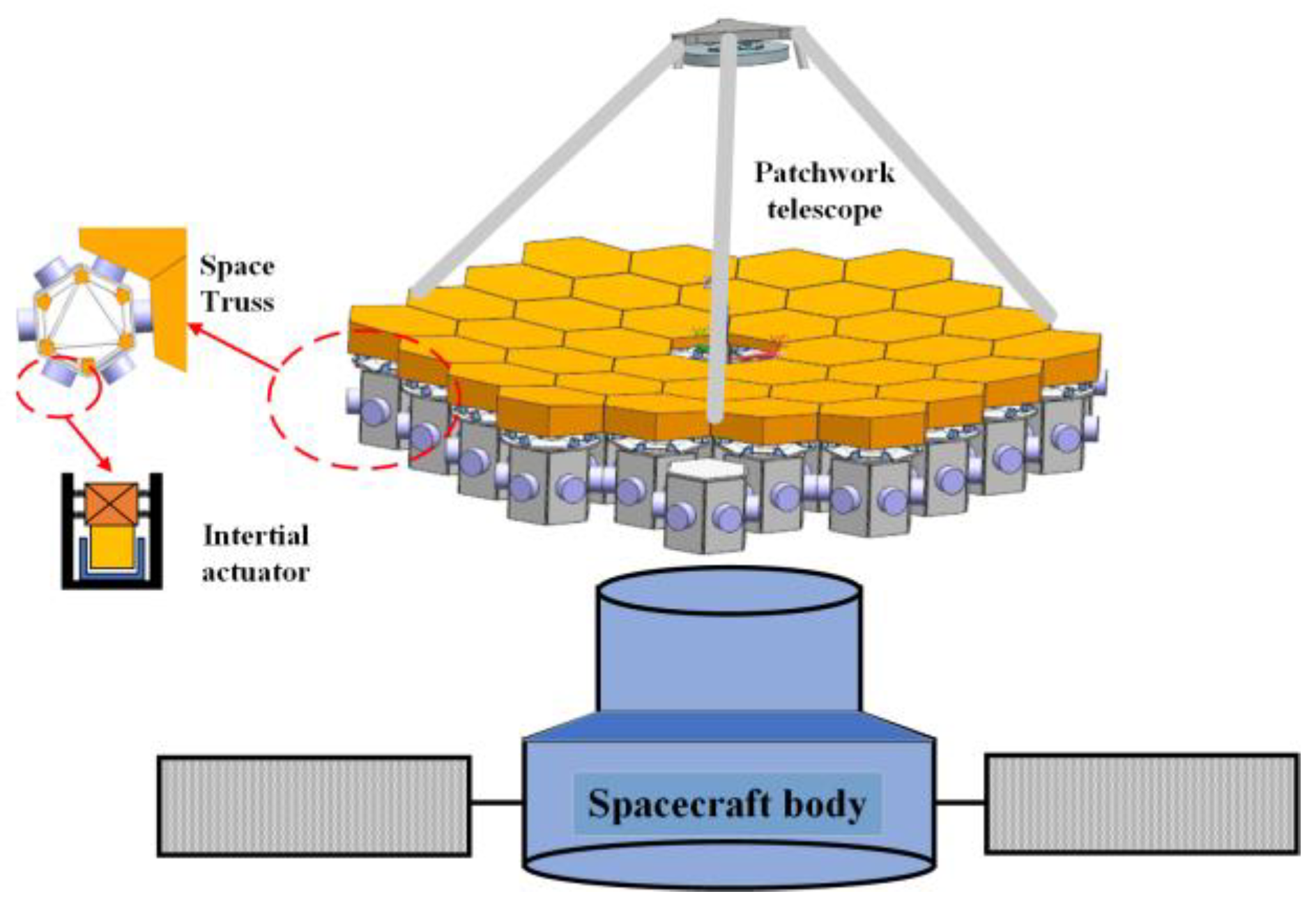
2. Mathematical Modeling of Space Truss and Inertial Actuators

The on-orbit assembled spliced telescope truss serves to connect each sub-mirror. However, due to the insufficient rigidity of the truss, the harmonic vibration generated on the spacecraft body will be transmitted to each sub-mirror by the truss, resulting in mirror vibration and a deterioration in imaging quality. The proposed scheme in this paper employs the use of inertial actuators on the truss to actively offset the vibration. The distribution of these actuators is illustrated in Figure 1.

2.1. Dynamic Modeling of Space Truss Structures

The space truss model comprises a rod unit, a beam unit, and a centralized mass unit. The mass matrix and stiffness matrix of each unit can be integrated to obtain the overall mass matrix and stiffness matrix.
Assuming that the displacements of any segment connected to a node are identical at the node and that their forces on the node are balanced with the external load of the node, the integration process can be expressed as follows:
{ M E = i = 1 n M i e K E = i = 1 n K i e δ E = i = 1 n δ i
The symbol denotes that the mass parameter, M i e , and stiffness parameter, K i e , of each node unit are arranged in the order of displacement to obtain the overall mass matrix, M E , and stiffness matrix, K E . The displacement vectors, δ i , of each node are arranged according to the structure in order to obtain a matrix of minor displacement changes in the overall coordinates, δ E . In this context, n represents the overall number of degrees of freedom of the structural system. The space truss model is composed of three fundamental units: a rod unit, a beam unit, and a centralized mass unit. The overall mass matrix and stiffness matrix can be obtained by applying the linear finite element method to integrate the mass matrix and stiffness matrix of each unit.
The kinetic energy of the structural system can then be expressed as:
T E = 1 2 δ ˙ E T M E δ ˙ E
The potential energy of the system can be expressed as:
V E = 1 2 δ E T K δ E
It is assumed that the non-conservative forces of the system are the damping force, EE, and other external forces, FE. The system dynamics equations of the space truss structure can be obtained through the Lagrange equation as follows:
M E δ ¨ E + E E + K E δ E = F E
In the absence of air in space, the damping of a system is primarily structural. The magnitude of the structural damping coefficient, g, is proportional to the structural damping force, E E , which is in turn proportional to the system displacement, with a phase difference of 90°.
E E = j g K E δ E , j = 1
M E δ ¨ E + j g K E δ E + K E δ E = F E
can be simplified to give
M E δ ¨ E + 1 + j g K E δ E = F E
1 + j g K E denotes the system’s complex stiffness.
Due to the linear system, the mathematical solution is straightforward. In engineering, alternative forms of damping are often considered in accordance with their energy loss over a cycle. This principle can be converted into an equivalent viscous damping.

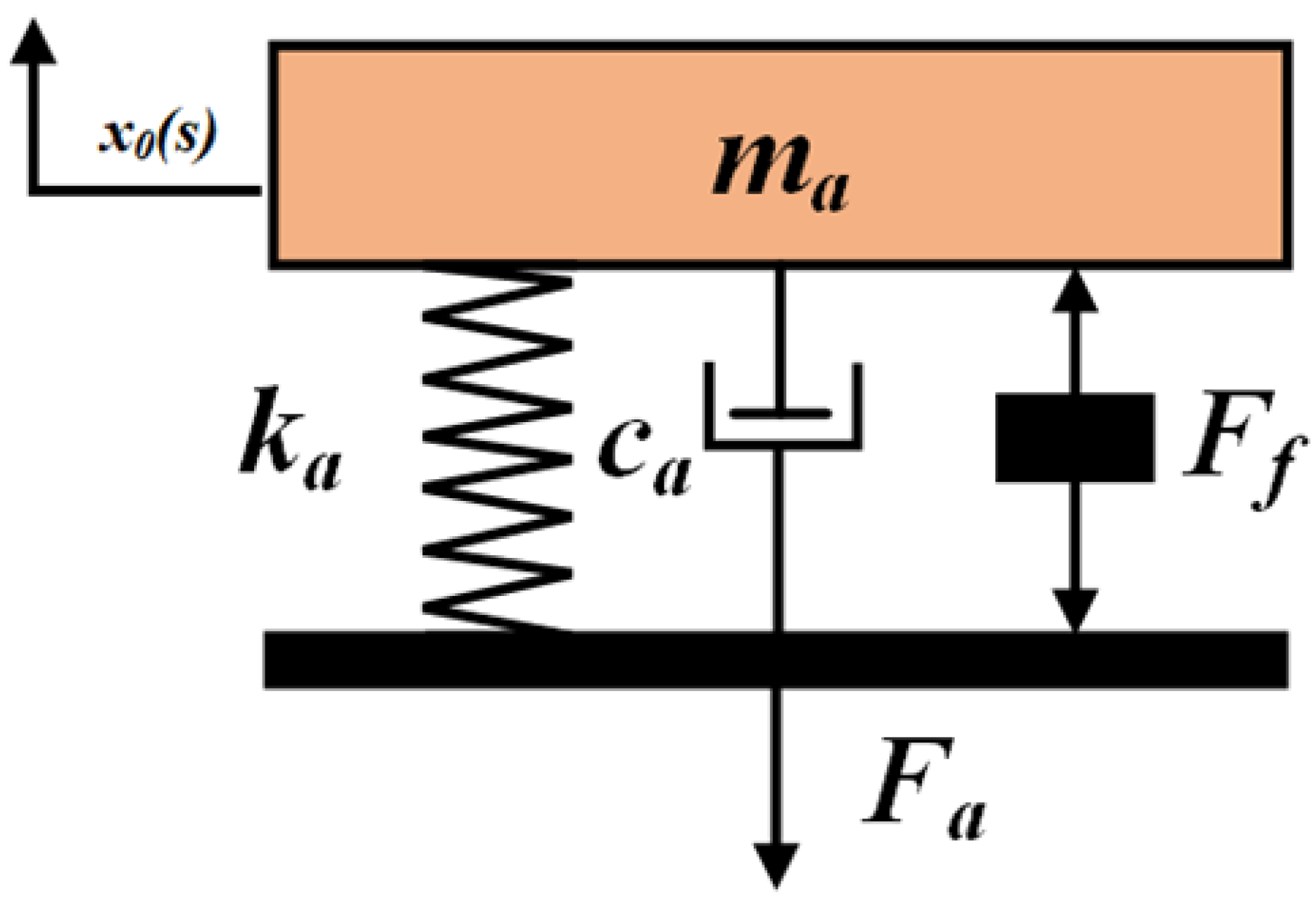
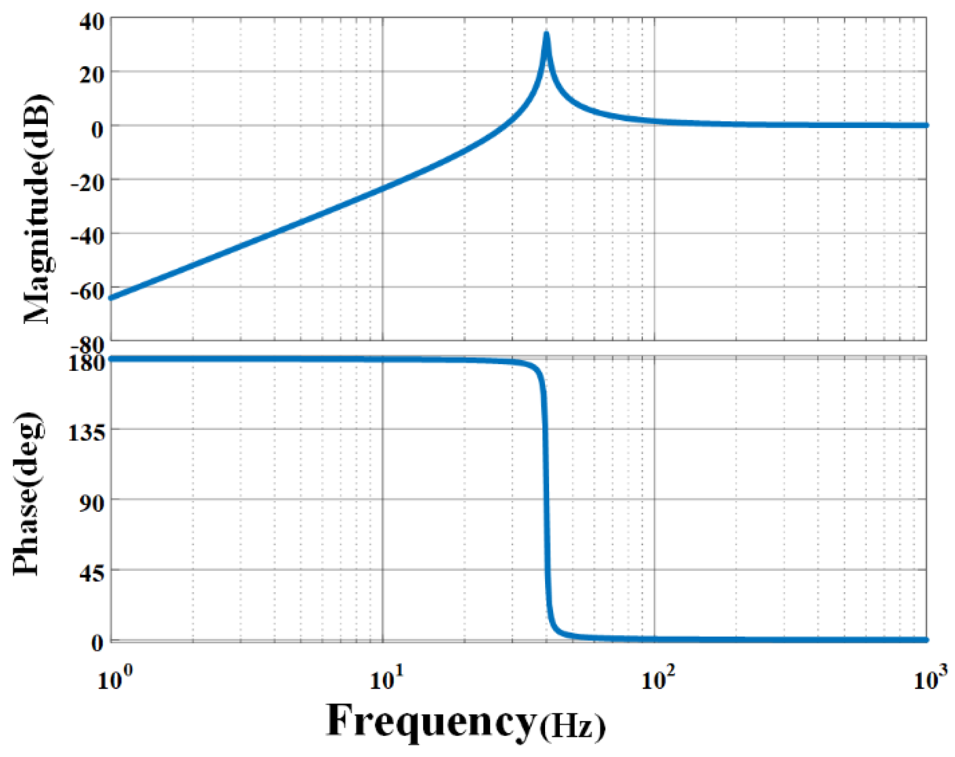
2.2. Mathematical Modeling of Inertial Actuators

The implementation of a DVA can effectively address the vibration suppression issue of the aforementioned structure. The fundamental principle of DVA vibration suppression is as follows: the attachment of a spring-mass block system to the structure results in the generation of a reverse force upon the structure when it vibrates, thereby suppressing the vibration of the structure. The inertial actuator is depicted in Figure 2. It is possible to enhance the control bandwidth and control effect of active DVA by applying an active control force. The inertial exciter system consists of the spring stiffness (ka) and damping coefficient (ca) generated by a voice coil motor, in addition to which an electromagnetic excitation force (Ff) can be generated by the voice coil motor that is positively correlated with the input current (Iin).
x 0 s I i n s = G 1 G 2 m a s 2 + c a s + k a
In this context, G1 represents the electromagnetic gain, while G2 denotes the power amplifier gain. The reaction force (Fa) exerted on the support base is a function of the mass and acceleration of the actuator.
m a x ¨ 0 = c a x ˙ 0 k a x 0 + F f = F a
This gives the transfer function between the reaction force, Fa, and the input current, Iin:
F a s I i n s = G 1 G 2 m a s 2 m a s 2 + c a s + k a = g a s 2 s 2 + 2 ξ 1 ω 1 + ω 1 2
If the intrinsic frequency of the shaker is set to 40 Hz, the efficiency is low in the interval below 40 Hz (the mass is taken as 1), and higher than the interval of 90 Hz in order to achieve the approximate. In the context of a 1:1 output, the actuator’s operation within a stabilized frequency interval negates the necessity to consider the dynamics of the actuator itself. This is demonstrated in Figure 3, which illustrates the linear relationship between the active force and the output force.

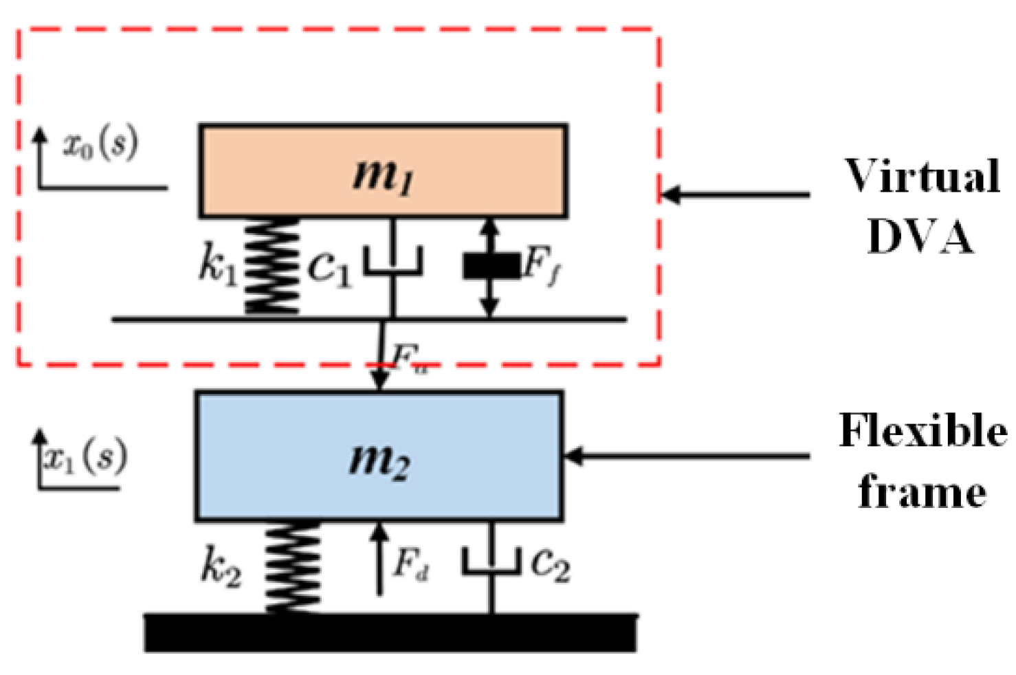
3. Virtual DVA Trap Fusion Active Vibration Suppression Algorithm Design

3.1. Virtual DVA and Traps

The dynamics of the space truss can be represented by two sets of second-order ordinary differential equations in the time domain. The writing of Equation (7) in its general form can be expressed as follows:
M X ¨ 1 + C X ˙ 1 + K X 1 = F d + B u
y = H a X ¨ 1 + H v X ˙ 1 + H d X 1
The displacement vector representing the displacement change on the truss is denoted as X1. The mass, damping, and stiffness of the truss to be controlled are represented by M, C, and K, respectively. The matrix order is u, which is the control matrix of the actuator matrix B. Finally, Fd represents the externally stimulated perturbation vector of the system, which is the vibration transmitted to the truss by the spacecraft. The measurement vector y is the matrix of and H a ,   H v ,   a n d   H d , the gain matrices of acceleration, velocity, and displacement, respectively. The measurement vector y can be used directly as direct state feedback or indirectly as an input to the controller.
Suppose that the modeling form of a controller with a second-order dynamical system can be represented as:
M c X ¨ c + C c X ˙ c + K c X c = B c u c
y c = H a c X ¨ c + H v c X ˙ c + H d c X c
The order virtual displacement matrix, X c , is denoted by the subscript. The virtual mass, damping, and stiffness matrices, M c ,   C c ,   a n d   K c , respectively, are represented by the subscript uc. The control matrix of the actuator, Bc, is represented by the subscript. The virtual measurements, yc, are represented by the subscript. The gain matrices of the controller’s acceleration, velocity, and displacement, respectively, are represented by the subscripts H a c ,   H v c ,   a n d   H d c . The closed-loop control system is then constituted by coupling the system to the controller.
Then, the controller is assumed to be
u c = y = H a X ¨ 1 + H v X ˙ 1 + H d X 1
The structural dynamics equation of the system under control conditions can be obtained by:
M t X ¨ t + C t X ˙ t + K t X t = F t
M t = M B H a c B c H a M c C t = C B H v c B c H v C c K d = K B H d c B c H d K c F t = F d 0 X t = X X c
In essence, the inertial actuator will operate at its intrinsic frequency. The active output force of the motor and the overall output force of the inertial actuator will exhibit a linear relationship with the principle of the virtual vibration absorber, as demonstrated in the figure. As illustrated in Figure 4, the active control can be increased to realize the principle of the virtual DVA. The equations of motion of a single-degree-of-freedom system can be expressed as follows:
m 2 x ¨ 1 + c 2 x ˙ 1 + k 2 x 1 = F d c 1 x ˙ 0 x ˙ 1 k 1 x 0 x 1 + f f
m 1 z ¨ 0 + c 1 z ˙ 0 + k 1 z 0 = m 1 x ¨ 1 + f f ,   z 0 = x 0 x 1
The symbols m 1 ,   c 1 ,   a n d   k 1 ,   r e s p e c t i v e l y , represent the mass damping and stiffness of the virtual absorber. Similarly, m 2 ,   c 2 ,   a n d   k 2 , r e s p e c t i v e l y , denote the mass damping and stiffness of the structure. Finally, x ¨ 0 , x ˙ 0 ,   a n d   x 0 represent the absolute displacement velocity. The symbols x ¨ 1 , x ˙ 1 ,   a n d   x 1 represent the absolute displacement velocity, acceleration, and jerk of the structural frame, respectively. The symbols z 0 ,   z ˙ 0 ,   a n d   z ¨ 0 r represent the relative displacement velocity, acceleration, and jerk, respectively, between the structural frame and the inertial mass.
The virtual passive controller can be designed as a passive damper by setting x c = z 0 , M c = B c = m 1 C c = c 1 , K c = k 1 . This configuration employs acceleration feedback with a configured sensor–actuator, which gives u c = y = x ¨ 1 ,   a n d   y c = u . Furthermore, a frequency-specific trapping waveform can be added by employing direct acceleration feedback.
F f = g u k 1 + c 1 s m 1 s 2 + c 1 s + k 1 s 2 + 2 ξ n o t c h 1 ω n + ω n 2 s 2 + 2 ξ n o t c h 2 ω n + ω n 2 x ¨ 1
Then, the combined force acting on the frame is
F c o u p l i n g = g u k 1 + c 1 s m 1 s 2 + c 1 s + k 1 s 2 + 2 ξ n o t c h 1 ω n + ω n 2 s 2 + 2 ξ n o t c h 2 ω n + ω n 2 x ¨ 1
gu denotes the controller feedback gain, ω n denotes the trap frequency, ξ n o t c h 1 denotes the trap factor 1, and ξ n o t c h 2 denotes the trap factor 2.

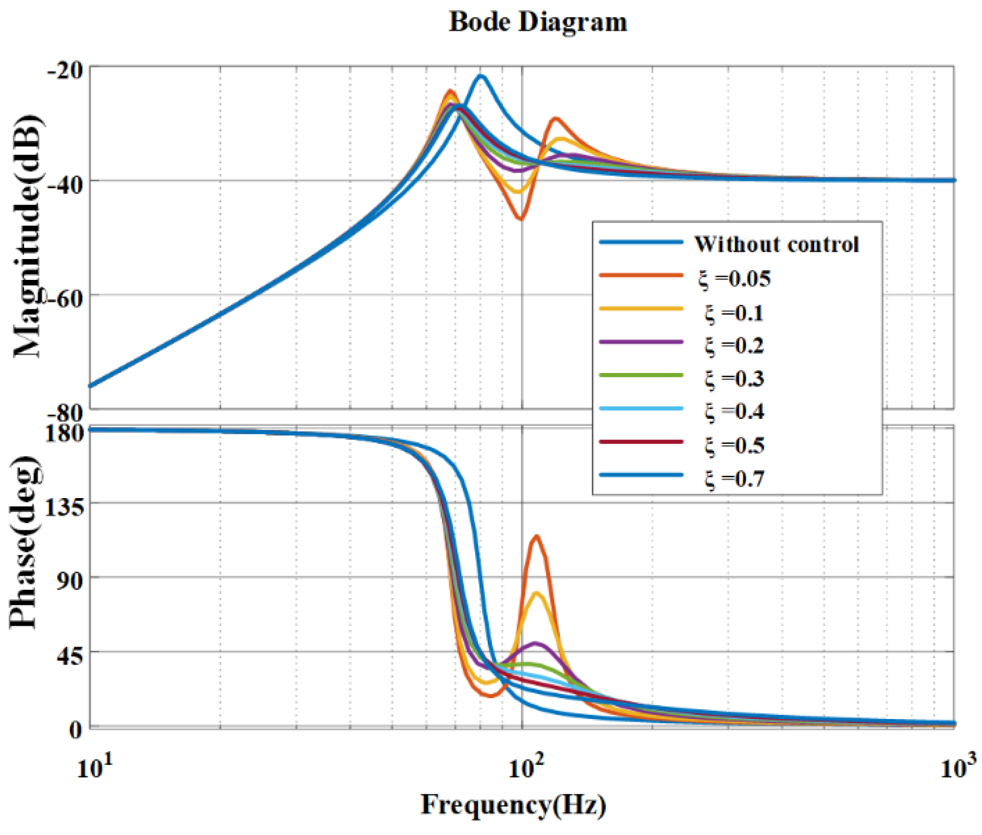
3.2. Parameter Analysis

To establish the single-degree-of-freedom system equations, the frequency of the flexible frame is set to 80 Hz. The specific parameters are shown in Table 1.
Let the fundamental frequency of the system be 80 Hz, the virtual mass of the virtual vibration absorber be m1 = 5 kg, and the virtual stiffness be k1 = 1.9739 × 10⁶ N/m. The fundamental frequency to be controlled is 100 Hz, and the transfer function from the perturbed force to the acceleration of the response of the main system can be expressed as follows:
G m a i n s = s 2 100 s 2 + 1000 s + 2.5266 × 1 0 7
The virtual DVA controller is represented by the transfer function
G m a i n s = g u 314 s + 1.9739 × 1 0 6 5 s 2 + 314 s + 1.9739 × 1 0 6
The damping ratio of the virtual vibration absorber is set to 0.05, and the gain is set to 0.1, 0.5, 1, 1.5, 2, and 3, respectively. As illustrated in Figure 5, it can be observed that when the gain of the controller becomes large, it directly affects the closed-loop transfer characteristics of the system. As the gain increases, the vibration transfer of the system at the frequency of the virtual vibration absorber decreases. This can reduce the resonance peaks of the system. However, if the gain is too large, it can cause the amplification of vibration in other frequency bands, which can destabilize the system.
The controller gain of the virtual vibration absorber is uniformly set to 3, and the damping ratio of the virtual vibration absorber is varied between 0.05, 0.1, 0.2, 0.3, 0.4, 0.5, and 0.7. From Figure 6, it can be observed that the damping ratio of the virtual vibration absorber is less than the vibration transmission at the virtual vibration absorber frequency. This results in a reduction in the resonance peak of the system, although the damping ratio is insufficiently large, which can lead to an amplification of vibration in the frequency band, following the frequency of the virtual vibration absorber, and an increase in system instability. However, a damping ratio that is too small will result in the amplification of vibration in the frequency band subsequent to the virtual shaker itself, which will in turn lead to the instability of the system.
The controller gain of the virtual vibration absorber is set to 3, and the damping ratio of the system is 0.05. The closed-loop transfer curves of the perturbation force to the system response of the theoretical vibration suppression using different methods are shown in Figure 7. It can be observed that the vibration attenuation of the virtual vibration absorber at 100 Hz is reduced by 3.4 dB compared to that of the uncontrolled vibration absorber, while the vibration attenuation using the trapping waveform control is reduced by 1 dB. This reduction in vibration attenuation may potentially lead to system instability. The vibration attenuation is reduced by 3.4 dB at 100 Hz with the virtual power absorber alone and 1 dB with the trapped wave control. It is therefore evident that the trapped wave control, when employed in isolation, is susceptible to causing system instability.
Table 2 presents the vibration attenuation of the frame system under varying operational conditions and distinct control schemes. Figure 8 illustrates the damping effect of the inertial actuator on 100 Hz single-frequency vibration under different control schemes. The root-mean-square value of the system without control is 2.9425 m/s2, while the vibration attenuation with the control of the virtual vibration absorber is 83.24% (0.4933 m/s2) and 92.32% (0.2261 m/s2) with the control of the virtual vibration absorber plus the trapping method. The figure illustrates the damping effect of the inertial actuator on 100 Hz and 150 Hz multi-frequency vibrations under different control schemes. The root-mean-square value of the system in the absence of control was 2.3425 m/s2, while the value with vibration attenuation of 16.5% when controlled by the virtual shaker was 1.9560 m/s2. The value with vibration attenuation of 88.85% when controlled by the virtual shaker plus the trapping method was 0.2612 m/s2. The vibration attenuation is 88.85% for 0.2612 m/s2 when controlled by the virtual absorber plus trap. A comparison of the results indicates that the use of a virtual vibration absorber for the control of single-frequency vibrations is more effective than the use of a single absorber. However, the efficacy of the absorber is considerably diminished when employed to regulate multi-frequency vibrations. Nevertheless, the incorporation of a trap into the absorber system enables the control of multi-frequency disturbances.

4. Experimental Methods

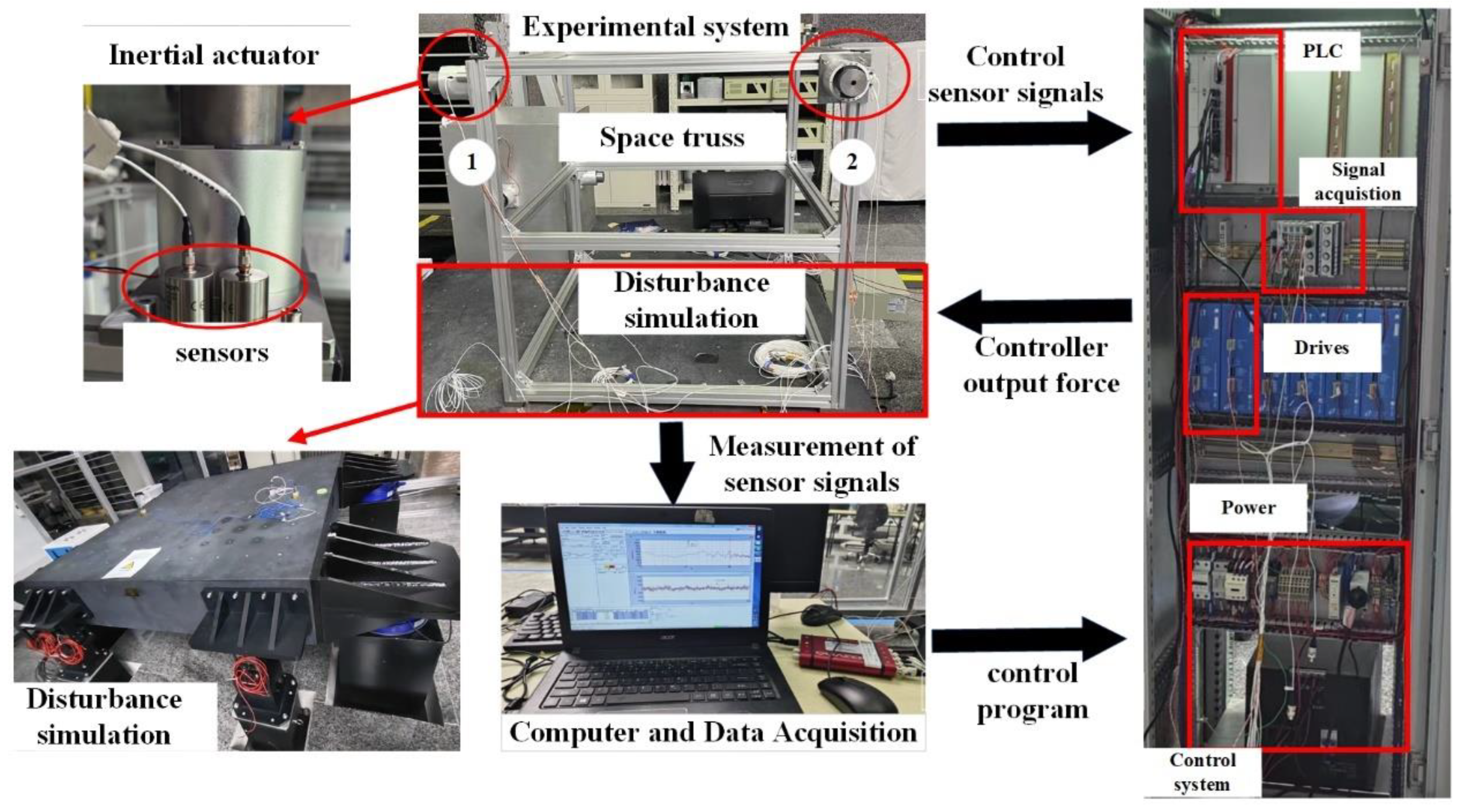
4.1. The Experimental Equipment Contains the Physical Inertial Exciter

The configuration of the hardware platform of the experimental system is illustrated in Figure 9. It comprises four distinct components: the electrical control of the mechanical system, the electronic control system, the host computer, and the data detection system. The mechanical system incorporates a disturbance simulator, which is employed to simulate the vibration of a fixed frequency generated by the support module. Furthermore, the system incorporates two inertial actuators, which are employed to output the excitation force, and a frame constructed from aluminum profiles to simulate a flexible support frame. Two acceleration sensors (PCB393B05, 10 V/g) are affixed to each inertial actuator, and the controller is a PLC. The control system employs the acceleration signal, generated by the sensor, to regulate the operation of the drive motor, providing feedback on the system’s movement. Upon receipt of the corresponding drive signal by the controller, the motor is initiated and subsequently amplified by the inertial actuator to generate the desired force. Figure 10 illustrates the configuration of the inertial exciter and depicts its initial response. The modal state exhibits a first-order intrinsic frequency of 38.3158 Hz. Given that the frequency of the space cooler and other frequencies are predominantly 100 Hz and its octave, the inertial actuator employed in this experiment has a favorable working frequency. The brake is firmly affixed to the controlled position of the truss via screws. The inertial actuator utilized in this experiment demonstrates satisfactory linearity at the operating frequency.
In Section 4.2, we discuss and utilize a single actuator to control the vibration of a single point on the truss. In Section 4.3, we discuss the use of multiple actuators to control the vibration of multiple points on the truss. Finally, we present our findings on the vibration suppression effects observed in both the time and frequency domains.

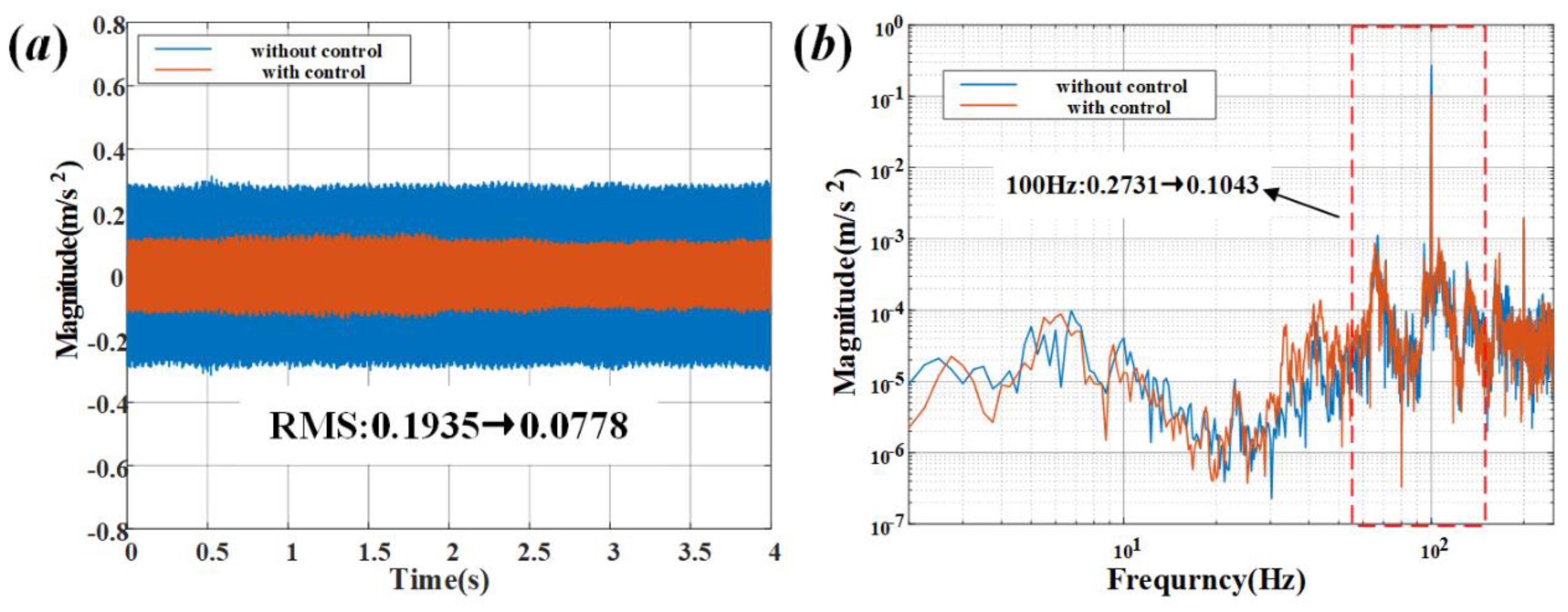
4.2. Truss Vibration Single-Degree-of-Freedom Control Algorithm Realization

A vibration simulation platform is employed to excite the truss, with a 100 Hz fixed frequency perturbation generated by the vibration simulator. It is observed that inertial actuator 1 is operational, while inertial actuator 2 remains inactive. The acceleration sensor is utilized to quantify the acceleration response of the inertial actuator 1 location, with and without the incorporation of active control. The mounting position is illustrated in Figure 9. The controller of the virtual vibration absorber is designed in accordance with Table 3.
The blue curve in Figure 11a depicts the vibration excitation time-domain response value of point 1, while the red curve depicts the vibration excitation time-domain response value of point 1 after vibration control. The vibration RMS value of point 1 was attenuated from 0.1935 m/s2 to 0.0778 m/s2, with an attenuation rate of 59.79%. Figure 11b depicts the frequency domain response value of the vibration excitation of point 1, with the blue curve representing the original response and the red curve representing the response after vibration control. The 100 Hz vibration response value is attenuated from 0.2731 m/s2 to 0.1043 m/s2, with an attenuation rate of up to 61.81%.
A vibration simulation platform was employed to excite the truss. The vibration simulator generated 100 Hz and 200 Hz fixed frequency perturbations. Inertial actuator 1 was found to be operational, whereas inertial actuator 2 was not. The acceleration sensor was utilized to assess the acceleration response of inertial actuator 1 at the location of inertial actuator 1 with and without the active control intervention. The controller of the virtual vibration absorber is designed in the form of the addition of two virtual vibration absorbers. The final force is the combined force of the two virtual vibration absorbers plus the trap.
The blue curve in Figure 12a depicts the vibration excitation time-domain response value of point 1, while the red curve depicts the vibration excitation time-domain response value of point 1 after vibration control. The vibration RMS value of point 1 was attenuated from 0.2091 m/s2 to 0.1121 m/s2, with an attenuation rate of up to 46.39%. Figure 12b depicts the vibration excitation frequency-domain response value of point 1, with the blue curve representing the original response and the red curve representing the response after vibration control. The 100 Hz vibration response value is attenuated from 0.2693 m/s2 to 0. 1042 m/s2, the vibration was attenuated by 61.31% at 100 Hz, and the 200 Hz vibration response value is attenuated from 0.0559 m/s2 to 0.0094 m/s2, where the attenuation rate reached 83.18% at 200 Hz.
When controlling the single-degree-of-freedom system, the combination of virtual DVA and wave trap can effectively suppress the disturbance of the system at a fixed frequency. Furthermore, the harmonic vibration suppression of single- and multi-frequency of single-degree-of-freedom can reach more than 60%, and the system is stable.

4.3. Truss Vibration Multi-Degree-of-Freedom Control Algorithm Realization

The truss is excited using a vibration simulation platform, the vibration simulator outputs a 100 Hz fixed frequency perturbation, and both inertial actuator 1 and inertial actuator 2 are working. The acceleration response of the location of inertial actuators 1 and 2 is measured using acceleration sensors with and without the active control added. In order to mitigate the impact of non-correlated frequency signals, a 300 Hz low-pass filter was incorporated into the acquisition process. The controller design of the virtual vibration absorber is shown in Table 3.
The blue curve in Figure 13a depicts the time-domain response value of vibration excitation of point 1, while the red curve depicts the time-domain response value of vibration excitation of point 1 after vibration control. The vibration RMS value of point 1 was attenuated from 0.1935 m/s2 to 0.0750 m/s2, resulting in an attenuation rate of up to 63.57%. The blue curve in Figure 13b depicts the vibration excitation frequency-domain response value of point 1, and the red curve depicts the vibration excitation frequency-domain response value of point 1 after vibration control. The vibration response value at 100 Hz is attenuated from 0.2731 m/s2 to 0.1016 m/s2, with an attenuation rate of up to 62.80%.
The blue curve in Figure 13c depicts the vibration excitation time-domain response value of point 2, and the red curve depicts the vibration excitation time-domain response value of point 1 after vibration control. The vibration RMS value achieved an attenuation rate of up to 62.91%. The blue curve in Figure 13d depicts the vibration excitation frequency-domain response value of point 2, while the red curve depicts the vibration excitation frequency-domain response value of point 2 after vibration control. The 100 Hz vibration response value achieved a rate of up to 65.53%.
The controller design of the virtual vibration absorber during multi-frequency control is presented in Table 4. The blue curve in Figure 14a depicts the vibration excitation time-domain response value of point 1, while the red curve depicts the vibration excitation time-domain response value of point 1 after vibration control. The vibration RMS value of point 1 is attenuated from 0.2091 m/s2 to 0.1014 m/s2, with an attenuation rate of 65.05%. Figure 14b depicts the vibration excitation frequency-domain response value of point 1, with the blue curve representing the original response, and the red curve representing the response after vibration control. The 100 Hz vibration response value is attenuated from 0.2693 m/s2 to 0.089 m/s2, indicating a 66.95% attenuation rate. The 200 Hz vibration response value is attenuated from 0.0559 m/s2 to 0.0078 m/s2, an attenuation rate up to 86.05%.
The blue curve in Figure 14c depicts the vibration excitation time-domain response value of point 2, and the red curve depicts the vibration excitation time-domain response value of point 2 after vibration control; its vibration RMS value is attenuated from 2.0344 m/s2 to 0.7303 m/s2, with an attenuation rate of up to 64.10%. In Figure 14d, the blue curve depicts the vibration excitation frequency domain response value of point 2, the red curve describes the vibration excitation frequency domain response value of point 2 after the vibration control of point 1, and its 100 Hz vibration response value is attenuated from 2.868 m/s2 to 1.048 m/s2, with the attenuation rate up to 63.64%, Its 200 Hz vibration response value is attenuated from 0.2212 m/s2 to 0.0568 m/s2; the attenuation rate can reach 74.32%.
The combination of virtual DVA and trap can effectively suppress the disturbance of a multi-degree-of-freedom system at a fixed frequency. In comparison to a single-degree-of-freedom system, there is no attenuation of the vibration suppression effect. At the same point, the harmonic vibration suppression of the multi-degree-of-freedom single-frequency and multi-frequency can reach more than 60%. In comparison to the vibration suppression effect of the single-point vibration, the vibration attenuation is almost identical, and the system is stable.

5. Conclusions

This paper presents a novel scheme for the harmonic vibration suppression of the truss of an ultra-large space telescope, achieving control over multiple degrees of freedom and frequencies without modifying the truss’s structure or stiffness. The study examines the effective bandwidth of the inertial actuator and proposes an active vibration suppression algorithm based on virtual DVA trap fusion. The algorithm in question is effective in suppressing harmonic vibrations at fixed frequencies.
In single-frequency excitation, the proposed algorithm exhibits a 9.08% greater degree of vibration attenuation in comparison to the pure virtual DVA algorithm. In the case of multi-frequency excitation, the vibration attenuation of the algorithm is observed to be 72.35% higher than that of the simple virtual DVA algorithm. Experimental verification demonstrates the efficacy of robust vibration suppression under both single-frequency and multi-frequency excitation in single-degree-of-freedom and multi-degree-of-freedom scenarios. The algorithm demonstrates resilience to the coupling effects of the system, achieving vibration suppression efficiency exceeding 60% in multi-frequency and multi-degree-of-freedom control.
It should be noted, however, that the present study is not without limitations and assumptions. The efficacy of the algorithm is contingent upon the meticulous implementation and calibration of the inertial actuators and the virtual DVA system. Any discrepancies or inaccuracies in these components could have an adverse effect on the overall vibration suppression performance. Furthermore, the practical applicability of this algorithm necessitates further investigation, particularly in the context of varying environmental conditions and operational scenarios that a large space telescope might encounter.
To further enhance control efficacy and address the intricate coupling phenomena that emerge with an augmenting number of DVAs, prospective research endeavors may contemplate the implementation of target modal decoupling. The aforementioned coupling phenomena can be addressed in the modal space, which may result in a reduction in system complexity and an enhancement of vibration suppression effectiveness.
Future research should concentrate on conducting long-term experiments in a greater variety of settings, including in-orbit testing. Further optimization of the algorithm could enhance its robustness and efficiency, thereby rendering it a viable solution for harmonic vibration suppression in large space telescope support trusses and other similar applications. Miniaturization and integration of inertial actuators should be considered for future space applications. Moreover, this method has considerable potential for the active vibration suppression of large flexible truss equipment, high-precision spatial optical loads, and shell equipment.

Author Contributions

Conceptualization, C.Q. and A.X.; formal analysis, C.H.; funding acquisition, Z.X.; investigation, C.H.; methodology, C.Q., A.X. and Z.X.; project administration, Z.X.; software, S.H.; supervision, S.H. and Z.X.; validation, C.Q., S.H. and C.H.; visualization, C.H.; writing—original draft, A.X.; writing—review and editing, C.Q. All authors have read and agreed to the published version of the manuscript.

Funding

This research was funded by the National Natural Science Foundation of China, grant number (62235018).

Data Availability Statement

No new data were created or analyzed in this study. Data are contained within the article.

Conflicts of Interest

The authors declare no conflicts of interest.

References

  1. Kuang, Y.; Wang, S.; Gao, Y.; Xu, B.; Xu, S. Design and Preliminary Ground Experiment for Deployable Sunshade Structures of a Modular Space Telescope. Sensors 2024, 24, 2280. [Google Scholar] [CrossRef]
  2. Zhang, E.; Sai, H.; Li, Y.; Sun, X.; Zhang, T.; Xu, Z. Modular robotic manipulator and ground assembly system for on-orbit assembly of space telescopes. Proc. Inst. Mech. Eng. Part C J. Mech. Eng. Sci. 2024, 238, 2283–2293. [Google Scholar] [CrossRef]
  3. An, Q.; Zhang, H.; Wang, K.; Liu, X.; Li, H. Photonics Scanning Pentaprism System for the Integrated Inspection of Large-Aperture Telescopes. Sensors 2023, 23, 6650. [Google Scholar] [CrossRef]
  4. Majumder, R.; Reich, B.J.; Shaby, B.A. Modeling extremal streamflow using deep learning approximations and a flexible spatial process. Ann. Appl. Stat. 2024, 18, 1519–1542. [Google Scholar] [CrossRef]
  5. Feng, X.; Pan, C.; Xu, F. The Spatial Structure and Influencing Factors of the Tourism Economic Network in the Yangtze River Delta Urban Agglomeration. Tour. Hosp. 2024, 5, 60–79. [Google Scholar] [CrossRef]
  6. Xu, R.; Li, D.; Luo, Q.; Liu, W.; Jiang, J. Microvibration suppression of space truss structures using viscoelastic dampers with design parameter optimization. Proc. Inst. Mech. Eng. Part G J. Aerosp. Eng. 2016, 230, 539–553. [Google Scholar] [CrossRef]
  7. Bishop, J.A.; Striz, A.G. On using genetic algorithms for optimum damper placement in space trusses. Struct. Multidiscip. Optim. 2004, 28, 136–145. [Google Scholar] [CrossRef]
  8. Onoda, J.; Sano, T.; Minesugi, K. Passive damping of truss vibration using preloaded joint backlash. AIAA J. 1995, 33, 1335–1341. [Google Scholar] [CrossRef]
  9. Elias, S.; Matsagar, V. Research developments in vibration control of structures using passive tuned mass dampers. Annu. Rev. Control. 2017, 44, 129–156. [Google Scholar] [CrossRef]
  10. Kim, I.H.; Jung, H.J.; Kim, J.T. Numerical investigation of an MR damper-based smart passive control system for mitigating vibration of stay cables. Struct. Eng. Mech. 2011, 37, 443–458. [Google Scholar] [CrossRef]
  11. Aramendiz, J.; Fidlin, A. On the vibration control of semi-active friction dampers with piecewise defined contact geometries. Acta Mech. 2023, 234, 6297–6314. [Google Scholar] [CrossRef]
  12. Huang, X.; Huang, Z.; Hua, X.; Chen, Z. Investigation on vibration mitigation methodology with synergistic friction and electromagnetic damping energy dissipation. Nonlinear Dyn. 2023, 111, 18885–18910. [Google Scholar] [CrossRef]
  13. Samani, H.R.; Mirtaheri, M.; Zandi, A.P. The study of frictional damper with various control algorithms. Earthq. Struct. 2017, 12, 479–487. [Google Scholar]
  14. Djojodihardjo, H.; Jafari, M.; Wiriadidjaja, S.; Ahmad, K.A. Active vibration suppression of an elastic piezoelectric sensor and actuator fitted cantilevered beam configurations as a generic smart composite structure. Compos. Struct. 2015, 132, 848–863. [Google Scholar] [CrossRef]
  15. Okubo, H.; Ichikawa, H. Robust pole assignment for vibration control of flexible structures. J. Intell. Mater. Syst. Struct. 2001, 12, 3–9. [Google Scholar] [CrossRef]
  16. Umesh, K.; Ganguli, R. Shape and vibration control of a smart composite plate with matrix cracks. Smart Mater. Struct. 2008, 18, 025002. [Google Scholar] [CrossRef]
  17. Song, G.; Schmidt, S.P.; Agrawal, B.N. Experimental robustness study of positive position feedback control for active vibration suppression. J. Guid. Control. Dyn. 2002, 25, 179–182. [Google Scholar] [CrossRef]
  18. Luo, Y.; Zhang, X.; Zhang, Y.; Qu, Y.; Xu, M.; Fu, K.; Ye, L. Active vibration control of a hoop truss structure with piezoelectric bending actuators based on a fuzzy logic algorithm. Smart Mater. Struct. 2018, 27, 085030. [Google Scholar] [CrossRef]
  19. Guo, X.; Jiang, J. Optimization of actuator placement in a truss-cored sandwich plate with independent modal space control. Smart Mater. Struct. 2011, 20, 115011. [Google Scholar] [CrossRef]
  20. Li, Y.; Xu, M.; Chen, J.; Wang, X. Nonprobabilistic reliable LQR design method for active vibration control of structures with uncertainties. AIAA J. 2018, 56, 2443–2454. [Google Scholar] [CrossRef]
  21. Guo, J.; Tian, D.; Huang, H.; Guo, Z.; Feng, Z. Optimal Placements of Actuators and Robust ADP-Based Vibration Control for Large Flexible Space Structures. J. Vib. Eng. Technol. 2024, 12, 1291–1307. [Google Scholar] [CrossRef]
  22. Qiu, Z.C.; Yang, Y.; Zhang, X.M. Reinforcement learning vibration control of a multi-flexible beam coupling system. Aerosp. Sci. Technol. 2022, 129, 107801. [Google Scholar] [CrossRef]
  23. Zhou, W.; Zhang, K.; Wu, S.; Tan, S.; Wu, Z. Distributed cooperative control for vibration suppression of a flexible satellite. Aerosp. Sci. Technol. 2022, 128, 107750. [Google Scholar] [CrossRef]
  24. Zhao, T.; Tian, W.; Wang, H.; Liu, H.; Yang, Z. Optimized placement of piezoelectric actuator for multichannel adaptive vibration control of a stiffened plate. J. Aerosp. Eng. 2022, 35, 04021102. [Google Scholar] [CrossRef]
  25. Chen, H.J.; Bishop, R.; Agrawal, B. Payload pointing and active vibration isolation using hexapod platforms. In Proceedings of the 44th AIAA/ASME/ASCE/AHS/ASC Structures, Structural Dynamics, and Materials Conference, Norfolk, VA, USA, 7–10 April 2003; p. 1643. [Google Scholar]
  26. Yuan, Z.; Zhang, Z.; Zeng, L.; Zhu, L.; Li, X. Micropositioning and microvibration isolation of a novel hybrid active–passive platform with two-axis actuator for optical payloads. Mech. Syst. Signal Process. 2023, 204, 110764. [Google Scholar] [CrossRef]
  27. Magliacano, D.; Viscardi, M.; Ciminello, M.; Dimino, I. Feasibility study for a tonal vibration control system of a mounting bracket for automotive gearboxes. Int. J. Mech. 2016, 10, 403–410. [Google Scholar]
  28. Magliacano, D.; Viscardi, M.; Dimino, I. Active vibration control by piezoceramic actuators of a car floor panel. In Proceedings of the ICSV23: 23rd International Congress on Sound and Vibration, Athens, Greece, 10–14 July 2016. [Google Scholar]
  29. Zhai, J.; Li, S.; Tan, G.; Li, J.; Xu, Z.; Zhang, L. Structural Vibration Suppression Using a Reduced-Order Extended State Observer-Based Nonsingular Terminal Sliding Mode Controller with an Inertial Actuator. Machines 2022, 11, 1. [Google Scholar] [CrossRef]
  30. Mao, Q.; Yuan, W.; Wu, J. Design and experimental study of a multiple-degree-of-freedom vibration absorber by using an inertial actuator. Int. J. Struct. Stab. Dyn. 2024, 24, 2450006. [Google Scholar] [CrossRef]
  31. Yuan, L.; Li, Y.; Wang, L.; Liu, C.; Si, X.; Zhao, Z. A piezoelectric inertial actuator operating with elliptical drive and stick-slip drive modes. Sens. Actuators A Phys. 2024, 373, 115428. [Google Scholar] [CrossRef]
  32. Airimitoaie, T.-B.; Landau, I.D. Robust and Adaptive Active Vibration Control Using an Inertial Actuator. IEEE Trans. Ind. Electron. 2016, 63, 6482–6489. [Google Scholar] [CrossRef]
  33. Pereira, E.; Diaz, I.M.; Hudson, E.J.; Reynolds, P. Optimal control-based methodology for active vibration control of pedestrian structures. Eng. Struct. 2014, 80, 153–162. [Google Scholar] [CrossRef]
  34. Wang, C.; Zhou, X.; Shi, X.; Jin, Y. Variable Fractional Order Sliding Mode Control for Seismic Vibration Suppression of Uncertain Building Structure. J. Vib. Eng. Technol. 2022, 10, 299–312. [Google Scholar] [CrossRef]
  35. Raoufi, M.; Delavari, H. Experimental implementation of a novel model-free adaptive fractional-order sliding mode controller for a flexible-link manipulator. Int. J. Adapt. Control. Signal Process. 2021, 35, 1990–2006. [Google Scholar] [CrossRef]
Figure 1. Distribution of trusses of the spliced space telescope.
Aerospace 11 00764 g001
Figure 2. Inertial actuator principle.
Aerospace 11 00764 g002
Figure 3. Motor output force and inertial actuator interface output force transfer function.
Aerospace 11 00764 g003
Figure 4. Principle of virtual DVA.
Aerospace 11 00764 g004
Figure 5. Effect of controller gain on system dynamics characteristics.
Aerospace 11 00764 g005
Figure 6. Effect of different damping ratios of the virtual DVA on the dynamical characteristics of the system.
Aerospace 11 00764 g006
Figure 7. Characteristics of closed-loop dynamics of the system under different control schemes.
Aerospace 11 00764 g007
Figure 8. Vibration control simulation: (a) time-domain effect of single-frequency, (b) time-domain effect of multi-frequency.
Aerospace 11 00764 g008
Figure 9. Experimental system.
Aerospace 11 00764 g009
Figure 10. Inertial actuator: (a) inertial actuator (structural); (b) inertial actuator (physical); (c) inertial actuator first-order modal diagram.
Aerospace 11 00764 g010
Figure 11. Effect of single-degree-of-freedom single-frequency control: (a) time-domain damping effect, (b) frequency-domain damping effect.
Aerospace 11 00764 g011
Figure 12. Effect of single-degree-of-freedom multi-frequency control: (a) time-domain damping effect; (b) frequency-domain damping effect.
Aerospace 11 00764 g012
Figure 13. Multi-degree-of-freedom single-frequency control effect: (a) point 1 time-domain damping effect, (b) point 1 frequency-domain damping effect, (c) point 2 time-domain damping effect, (d) point 2 frequency-domain damping effect.
Aerospace 11 00764 g013
Figure 14. Multi-degree-of-freedom multi-frequency control effect: (a) point 1 time-domain damping effect, (b) point 1 frequency-domain damping effect, (c) point 2 time-domain damping effect, (d) point 2 frequency-domain damping effect.
Aerospace 11 00764 g014
Table 1. System parameters of the simulated flexible frame.
ParametersSymbolValue
Truss massm2 (kg)100
Truss stiffnessk2 (N/m)2.5266 × 107
Truss dampingc2 (N/(m/s))1000
Table 2. Response under different control methods for different operating conditions.
Disturbed Working ConditionControl MethodsResponse RMS (m/s2)
100 HzWithout control2.9425
100 HzDVA0.4933
100 HzDVA + notch0.2261
100 Hz + 150 HzWithout control2.3425
100 Hz + 150 HzDVA1.9560
100 Hz + 150 HzDVA + notch0.2612
Table 3. Parameters of single-frequency virtual DVA controller.
Virtual DVA 1SymbolValue
Virtual mass m 11 k g 5
Virtual natural frequency ω p 1 H z 100
Virtual damping ratio ξ p 1 0.05
Trap frequency ω n 1 H z 100
Trap factor 1 ξ n 11 0.005
Trap factor 2 ξ n 21 0.01
Table 4. Multi-frequency virtual DVA controller parameters.
Virtual DVA 1SymbolValueVirtual DVA 2SymbolValue
Virtual mass m 11 k g 5Virtual mass m 12 k g 5
Virtual natural frequency ω p 1 H z 100Virtual natural frequency ω p 2 H z 200
Virtual damping ratio ξ p 0.05Virtual damping ratio ξ p 2 0.05
Trap frequency ω n 1 H z 100Trap frequency ω n 2 H z 200
Trap factor 1 ξ n 11 0.005Trap factor 1 ξ n 12 0.005
Trap factor 2 ξ n 21 0.01Trap factor 2 ξ n 22 0.01
Disclaimer/Publisher’s Note: The statements, opinions and data contained in all publications are solely those of the individual author(s) and contributor(s) and not of MDPI and/or the editor(s). MDPI and/or the editor(s) disclaim responsibility for any injury to people or property resulting from any ideas, methods, instructions or products referred to in the content.

