Article

The Generation Mechanism of the Side Force and Yawing Moment of a Rotating Missile with Wrap-Around Fins

1
Beijing Institute of Technology, School of Aerospace Engineering, Beijing 100081, China
2
Xi’an Modern Control Technology Research Institute, Xi’an 710065, China
*
Author to whom correspondence should be addressed.
Aerospace 2024, 11(9), 765; https://doi.org/10.3390/aerospace11090765
Submission received: 18 June 2024 / Revised: 30 August 2024 / Accepted: 9 September 2024 / Published: 18 September 2024
(This article belongs to the Section Aeronautics)

Abstract

:
The rotation of a missile generates a side force perpendicular to the plane containing the attack angle and produces a yawing moment that tilts the body out of the plane, significantly affecting the flight stability of rotating missiles. The non-planar asymmetry of the wrap-around-fin rotating missile determines its more complex rotational effects. This study utilizes the dual time-step method to solve the unsteady Navier–Stokes equations, investigating the characteristics of the side force and yawing moment of the wrap-around-fin rotating missile under supersonic conditions and uncovering the mechanism behind the generation of the side force and yawing moment. The results reveal that the side force and yawing moment of the wrap-around-fin missile are composed of static values and induced values from rotation. The static side force and yawing moment of the wrap-around-fin missile are not zero, while those of the flat-plate-fin missile are zero. This difference is primarily caused by the non-axisymmetric nature of the wrap-around fin, resulting in the static side force and yawing moment of the wrap-around-fin missile being 40% greater than those of the flat-plate-fin missile. The rotation of the missile increases the effective angle of attack on the convex surface of the fin and decreases it on the concave surface, leading to an imbalance in the pressure changes on the windward and leeward sides. This is the main reason for the generation of the induced side force and yawing moment due to rotation. The induced values from rotation vary linearly with the rotation rate, and their magnitudes can be several times those of the static values.

1. Introduction

Long-range missiles typically have two stabilization methods. One seeks to provide gyroscopic stability through spin, and the other aims to generate stabilizing moments using tail fins. For tube-launched missiles to be implemented, the tail fins must be folded, and, among all the folding schemes, wrap-around fins that allow for circumferential folding are the optimal solution. To meet the speed and range demands of missiles and mitigate the mass imbalance, thrust misalignment, and aerodynamic asymmetry, as well as to streamline the control system, wrap-around-fin missiles commonly utilize rotational flight.
The coupling of the rotation rate of the spinning missile with cross-flow induces asymmetry in the flow on both sides of the attack angle plane, resulting in the generation of a side force and the corresponding yawing moment perpendicular to the attack angle plane, also known as the Magnus force and moment [1]. Research by Mikhail [2] and Guidos [3] has indicated that when the levels of the side force and yawing moment exceed a certain threshold, the rotating missile may exhibit motion instability. The Magnus effect of the wrap-around-fin rotating missile is more intricate than that of traditional flat-plate-fin missiles. The curvature of the tail fins produces an additional side force and yawing moment, which significantly impacts the striking precision and flight stability. Therefore, in-depth research on the flow mechanisms of the side force and yawing moment of the rotating wrap-around-fin missile is necessary.
In the early years, the Magnus force and moment of rotating missiles were extensively studied through theoretical analysis and experimental methods, such as wind tunnel tests and flight experiments. In 1957, Martin provided an empirical method for the estimation of the Magnus effect of a cylinder after analyzing the asymmetry of the boundary layer [4]. Feibig [5], Sedney [6], and Jacobson [7] successively proposed theoretical estimation methods for the Magnus effects of rotating cones. In 1965, Platou theoretically analyzed the contribution of the missile tail fins to the Magnus effect [8]. Alongside the development of theoretical tools, researchers also studied the Magnus effects of rotating missiles through experimental methods. The Arnold Engineering Development Center conducted multiple wind tunnel experiments on two differently shaped tail fin rotating missiles, obtaining aerodynamic parameters such as the Magnus force and moment for the two shapes under varying angles of attack, rotation rates, and Mach numbers [9].
Currently, most research is conducted on symmetrical shapes, while studies on the side force and yawing moment of wrap-around-fin missiles are relatively scarce. The main focus has been on the aerodynamics and moments of wrap-around-fin tails in a static state, particularly the self-induced rotational moment. Wu et al. [10,11] studied the self-induced rotation characteristics of wrap-around-fin missiles through wind tunnel experiments. Eastman et al. [12] conducted wind tunnel tests on a high-aspect-ratio wrap-around-fin shape, obtaining aerodynamic data at different angles of attack, tail mounting angles, and Mach numbers. Wind tunnel experiments provided reliable data for early research, offering insights into aerodynamic principles. However, these studies were often limited by the performance and precision of the experimental equipment, the flow field information provided was limited, and the wind tunnel experiments mostly focused on studying wing–body combinations. They were only able to record the time-averaged overall forces and moments, making it difficult to conduct in-depth research on the flow mechanisms during rotation.
In recent years, computational fluid dynamics has seen significant advancements and is now widely used in the design and optimization of aircraft. Currently, there is a greater focus on conventional symmetric aircraft in research. Abdullah et al. [13] used CFD techniques to evaluate the aerodynamic performance of the “Smokey Sam” prototype rocket design and validated the numerical results with experiments. Wu [14] employed numerical methods to investigate the lift and drag characteristics of wing shapes before and after optimization and established a subsonic/supersonic aircraft aerodynamic optimization method that considers the longitudinal trim achieved through control surface deflection. For wrap-around-fin missiles, many researchers have employed numerical simulation methods to investigate the aerodynamic characteristics in a non-rotating state. However, research on the rotating state of wrap-around-fin missiles is still relatively limited. Edge [15] and Abate [16] studied the side force and yawing moment of wrap-around-fin shapes by solving the Navier–Stokes equations. Edge studied the rotational moment characteristics of a quarter model of a wrap-around-fin missile using periodic boundary conditions [17] and compared the results with Dahlke’s experimental findings [18,19]. Tilmann et al. [20] used an algebraic eddy viscosity model to solve the Navier–Stokes equations and combined this with wind tunnel experiments to investigate the flow field characteristics near the wrap-around fin at Mach 4.9. Zhang et al. [21] used the Spalart–Allmaras turbulence model to calculate and study the rotational moment, side force, and yawing moment variations in wrap-around-fin shapes in a non-rotating state. Xiang et al. [22] simulated the rotation characteristics of wrap-around-fin missiles using CFD software. They investigated the effects of the tail mounting angles and trailing edge section sizes on the rotation characteristics. Song et al. [23] studied the aerodynamic characteristics of rotating wrap-around-fin missiles using a sliding mesh method and compared the results with those of wind tunnel experiments, exploring the impact of rotational motion on the missile’s aerodynamic parameters. Zhou et al. [24] used CFD methods to investigate the aerodynamic characteristics of a wrap-around-fin missile with differential rotation capabilities between the tail and the body, analyzing the effects of the differential rotation angular velocity on the roll moment and Magnus moment characteristics of the missile.
In previous studies, researchers used numerical simulation methods to investigate the aerodynamic effects of wrap-around-fin missiles. However, the focus was on studying the aerodynamic characteristics of the entire missile, mainly under static conditions. While some conclusions were reached, they were not comprehensive. The static aerodynamic characteristics of the wrap-around-fin missile are already complex, and the addition of rotational motion in the wrap-around-fin missile introduces even more intricate rotational aerodynamic effects, significantly increasing the difficulty of conducting relevant research. In practical flight, wrap-around-fin missiles are usually accompanied by risks of angular motion divergence. However, research on the aerodynamic characteristics of wrap-around-fin missiles under rotation is relatively scarce at present, highlighting the need for an in-depth study of the generation mechanism of the side force and yawing moment under rotational conditions. This study utilizes a numerical method based on the Reynolds-averaged Navier–Stokes equations and the SST k-ω turbulent model to numerically simulate the aerodynamic characteristics and flow field around a rotating wrap-around-fin missile. It decomposes the aerodynamic effects of the rotating wrap-around-fin missile into static and rotation-induced components, and the computational results are compared with those of a flat-plate-fin missile. It studies the impact of wing bending and rotational motion on the side force and yawing moment characteristics of the missile, uncovering the generation mechanism of the side force and yawing moment in wrap-around-fin missiles.

2. Numerical Approach

2.1. Numerical Methods

The control equations in this study adopt the integral form of the Navier–Stokes equations based on the implicit dual time-stepping method:
t V W d V + Γ ε V Q d V + [ F G ] d A = V H d V
W = { ρ ρ u ρ v ρ w ρ E } ,   Q = { p u v w T } ,   F = { ρ v ρ v u + p i ρ v v + p j ρ v w + p k ρ v E + p v } ,   G = { 0 τ x i τ y i τ z i τ i j v j + f } ,   Γ = [ θ 0 ρ T θ v ρ I ρ T v θ H δ ρ v ρ T H + ρ C P ]
where W is a convective term, Γ and Q denote the preconditioning matrix and the primitive variables, F and G are the inviscid and viscous flux vectors, H is the source term, and V represents the cell volume. In Equation (2), ρ represents the density, p denotes the pressure, τ is the shear stress, and v = [u, v, w] is the fluid velocity in the moving reference frame. In the preconditioning matrix, I represents the identity matrix, δ equals 1 in an ideal gas, Cp is the specific heat capacity, H is enthalpy, and the expressions for parameters θ and ρT are as follows:
ρ T = ρ T | p = c o n s t = p / R T 2 , θ = ( 1 / U r 2 ) ( ρ T / ρ C p )
where Ur is the local reference velocity; for an ideal gas, its expression is
U r = { λ c , | v | , c , | v | < λ c λ c < | v | < c | v | > c
where c is the speed of sound, and λ is a small quantity on the order of 10−5 to prevent singularities.
The finite volume method is used to solve the governing equations, the second-order upwind scheme is applied for spatial discretization, the Roe flux-difference splitting scheme is used for convective flux [25], and the gradient is solved using the least squares method. The rotation of the missile induces a strong shear flow, so the SST k-ω model [26] is employed in the numerical simulations of the rotational flow around the missiles. It accurately captures phenomena, such as shear flow from rotation, asymmetric adverse pressure-gradient flows, and asymmetric flow separation. The dual time-step method includes a physical time step describing the motion of the object, as well as an inner virtual time step to converge the Reynolds-averaged N-S equations. In this context, t denotes the physical time step, while ε signifies the virtual time step in the time integration algorithm. During numerical computation, the rotation rate is initially set to 0 for steady-state calculations. Then, transient calculations are performed using the results from the steady-state calculations as the initial condition, enabling the rapid and stable convergence of the results.

2.2. Sliding Mesh Technique

The sliding mesh technique is suitable for solving problems involving relative translation or rotational motion between grid domains [27,28]. The motion of a projectile is simulated by allowing for movement in the inner domain while keeping the outer domain fixed, and rotational motion is achieved by defining the rotation angular velocity for the inner grid. The connecting surface between the outer and inner grids is called the interface, and no normal relative motion is allowed between interfaces. Numerical interpolation is used during the calculations to ensure flux conservation between the two interfaces.
The sliding grid technique does not require the grid points on the two interfaces to coincide, as illustrated in Figure 1. Regions (1) and (2) are outer fixed domains, while regions (3) and (4) are inner moving domains. There are two overlapping interfaces, Interface-1 and Interface-2, between the regions. For example, the D-E surface is not considered when calculating the flux from the outer domain crossing the interface into the inner domain (3). Instead, the information from domains (1) and (2) is brought into domain (3) using the d-b and b-e surfaces to complete the data exchange between the inner and outer domains, ensuring flux conservation.
When applying the Navier–Stokes equations to solve flow fields based on slip grids, the basic set of control equations can be represented as
{ d d t ω ( t ) ρ d ( V ) + ω ( t ) ρ ( u D ) n d s = 0 d d t ω ( t ) ρ u d ( V ) + ω ( t ) [ ρ u ( u D ) + P ] n d s = ω ( t ) t n d s d d t ω ( t ) ρ e d ( V ) = ω ( t ) ρ e ( u D ) n d s ω ( t ) ( P u ) n d s ω ( t ) ( t u ) n d s ω ( t ) q n d s
where ω(t) represents the boundary surface of the control volume; ρ, u, and e denote the fluid density, velocity, and total energy per unit volume in the control volume, respectively; D denotes the grid velocity in the internal slip region; n represents the outward unit normal vector of ω(t); P denotes the fluid static pressure tensor; t is the viscous stress tensor; and q denotes the heat flux generated by heat conduction. In the external fixed region, D equals 0 in the control equations; for the internal moving region, D is equal to the grid velocity of the moving grid.

3. Computational Conditions and Validation

3.1. Models and Grids

The shape used in this study is the Technical Cooperation Program (TTCP) standard wrap-around-fin (WAF) shape [16], while a missile shape with a flat-plate fin (FPF) is set as a control. Figure 2 shows the schematic diagram of the basic external dimensions and moment reference point positions of the TTCP standard wrap-around-fin shape (left view and rear view), where the diameter of the projectile body is d = 0.1016 m, the reference length is the projectile length l, and the reference area is the cross-sectional area of the projectile body cylinder section. The geometric shape of the projectile body and the thickness, height, and projected area of the tail fin in the control group are the same as those of the TTCP shape. In this study, a positive rotation rate is defined as pointing toward the positive X-axis direction, meaning that the rotation rate is positive when the convex side of the wrap-around fin faces the wind and negative otherwise. Due to the asymmetry of the TTCP shape, the side force and yawing moment experienced during positive and negative rotation are completely different.
The distribution of the grid nodes for the two shapes considered in this study is the same, with an equal number of grids. The computational grid is composed of hexahedral structured grids with a total of 13 million cells, ensuring that the first layer grid height meets y+ < 1 and the wall grid growth rate is kept below 1.1. The rotational motion of the projectile is achieved using the sliding mesh technique, and the computational domain’s division is shown in Figure 3. Figure 4 shows the mesh topology structures of the two shapes.

3.2. Computational Conditions

In unsteady calculations, the dual time-stepping method involves 80 inner iterations, with a physical time step of ∆t = t/1440, where t = 2π/ω. The far-field boundary condition is applied to the outer boundary of the computational domain, with the incoming static pressure of p = 101,325 Pa and a static temperature of T = 300 K. The numerical computation includes Mach numbers of Ma = 1.25, 1.75, and 2.50; angles of attack α = 10° and 15°; and dimensionless rotation rates Ω = 0, ±0.009, and ±0.018.
For the two shapes mentioned above, the flow field around the missile exhibits four periodic variations within one rotation cycle, leading to identical aerodynamic coefficient waveforms repeating four times. Therefore, only the aerodynamic coefficient curves within the rotation angle range of φ = 0~90° will be presented in the following section.

3.3. Validation of Unsteady Numerical Methods

3.3.1. Validation of Rotation Method

To ensure the effectiveness of the unsteady numerical rotation method, the ANF shape [9] is used for validation, and the schematic of the ANF is shown in Figure 5. The reference length is equal to the projectile diameter, the reference area is the cross-sectional area of the projectile body, and the moment reference point is located at a distance of 6.1d from the head vertex. The calculation conditions are Ma = 2.49 and Ω = 0.01. The missile rotates at a fixed speed, with the rotation rate and flow conditions matching those of the wind tunnel test.
In Figure 6, a comparison is provided between the numerical simulation results and the wind tunnel test data from the Arnold Engineering and Development Center, where Cmy represents the yawing moment coefficient and CZ is the side force coefficient. For 10° < α < 20°, the coefficients obtained from the numerical simulations closely match the experimental results both quantitatively and in terms of the trend. The largest deviation between the numerical and experimental results is observed at α = 30°, reaching approximately 20%. Considering the relatively small values of the side force and yawing moment coefficients, this discrepancy falls within an acceptable range. To ensure the accuracy of subsequent calculations, α = 10° and 15° will be utilized for further computation.

3.3.2. Validation of Grid Independence and Time-Step Independence

To ensure the reliability of the computational results, grid independence and time-step independence validation are necessary. Table 1 shows the grid and time-step configuration for verification cases. Case A is set as the base case, while cases B and C have the same time steps as case A, but, under the condition of a consistent wall grid, the grids of cases B and C in the remaining areas are uniformly diluted or refined by a factor of ∛2. Cases D and E have the same grid as case A but with time steps in a multiple relationship to verify the time-step independence. The inflow conditions are p = 101,325 Pa, T = 300 K, α = 15°, Ma = 1.25, and ω = 314.16 rad/s.
Figure 7 and Figure 8 show the curves of the side force and yawing moment for the five cases with varying angles of rotation. From the figures, it can be observed that the error between the results of case A and cases B and E is within 0.5%. It is considered that the mesh and time-step settings of case A can meet the requirements of subsequent calculations. Therefore, the configuration of case A is used for the calculations in the subsequent work.

4. Results and Discussion

4.1. Time-Averaged Side Force and Yawing Moment Properties of Rotating Missile

4.1.1. Composition of Side Force and Yawing Moment

In the study of rotating tail fin missiles, a nonlinear aerodynamic model is typically required to describe the transient aerodynamic forces and moments of the missile [25]. This model considers the aerodynamic forces and moments of non-planar motion (such as coning). For tail fin rotating missiles, when the freestream velocity is constant and the center of mass does not move laterally, the missile’s moment coefficient is induced by various factors. To analyze the influence of different factors on the missile moment, it is necessary to decompose the total moment and separately discuss the effects of different factors on the missile’s side force and yawing moment. The missile moment coefficient can be represented by the following equation:
C m ( t ) = C m ( ; δ , φ ) + α ˙ l V C m α ˙ ( δ , φ ) + ω l V C m ω ( δ , φ ) + ϕ ˙ l V C m ϕ ˙ ( ; δ , φ )
where α is the angle of attack, φ is the rotation angle, ω is the rotation rate, ϕ ˙ is the coning rate, δ = sin α, l is the reference length, and Cm is the moment coefficient. Among the four terms on the right side of the equation, the first term is only related to the missile’s transient angle of attack and roll angle, representing the static moment coefficient; the second term represents the moment change induced by the rate of change of the attack angle; the third term represents the moment change induced by the roll rate; and the last term represents the moment change induced by the coning rate. The attack angle does not change when the missile rotates in this study, and the second term on the right-hand side can be omitted. Additionally, when coning is not considered, the fourth term on the right-hand side can also be omitted. In this case, Equation (6) can be written as
C m ( t ) = C m ( ; δ , φ ) + ω l V C m ω ( δ , φ )
Equation (7) reveals that, for a rotating missile without coning, the moment change is the result of the superposition of the static yawing moment and the induced yawing moment from the rotational rate. Therefore, when studying the side force and moment characteristics of the rotating missile, the decomposition of the side force and yawing moment is required.

4.1.2. Side Force and Yawing Moment Characteristics of Rotating Missile

By averaging the aerodynamic coefficients over one roll period, the time-averaged aerodynamic coefficient characteristics of the missile under specific flow conditions can be investigated. In Section 4.1.1, it is stated that the time-averaged side force and yawing moment of the two shapes studied comprise the static side force and moment and the induced side force and moment from the roll rate. Figure 9 and Figure 10 show the time-averaged side force and yawing moment coefficient curves of the two shapes at different Mach numbers and non-dimensional rotational rates. It can be observed from Figure 9 and Figure 10 that the side force and yawing moment of the two shapes exhibit a good linear relationship with the dimensionless rotation rate. As the Mach number increases, the slope of the curve gradually decreases; this pattern is observed in both the wrap-around-fin and flat-plate-fin shapes. When Ω = 0, the time-averaged Cz and Cmy of the flat-plate-fin missile are zero, whereas those of the wrap-around-fin missile are non-zero. In contrast to the flat-plate-fin missile, the wrap-around-fin missile exhibits a self-induced side force and yawing moment. When Ω ≠ 0, the time-averaged side force and yawing moment of the flat-plate fin are entirely induced by the roll rate, while the static side force and moment of the wrap-around fin contribute simultaneously with the roll rate to the time-averaged side force and moment. With the increase in the rotation rate, the proportion of the side force and yawing moment induced by rotation in the total force/moment gradually increases. When Ω approaches 0.02, it can reach around 1.5 times the static side force and yawing moment. With an increase in the angle of attack, the side force and yawing moment of the wrap-around-fin missile still exhibit a linear variation with the rotation rate. However, the coupling effect between the angle of attack and the rotational motion intensifies, leading to an increase in the side force and yawing moment induced by the rotation. This implies that, at different angles of attack, the rotation rates at which the side force and yawing moment of the wrap-around-fin missile are zero are different. This must be taken into consideration in the design and control of the wrap-around-fin rotating missile. When analyzing the mechanisms of side force and yawing moment generation in these two rotating missiles, it is necessary to consider the contributions of the static value and the roll rate-induced value separately.
The mechanism of side force and yawing moment generation in wrap-around-fin missiles is complex. To analyze the mechanism behind the differences in the side force and yawing moment characteristics between the two shapes, and to clarify the role of fin bending in them, the side force and yawing moment of the missile will be decomposed according to Equation (7), based on which the mechanism of side force and yawing moment generation on the body and the tail fins will be studied separately.
Figure 11 shows the transient side force and yawing moment curves of the wrap-around-fin missile over a quarter rotation; the parameters adopted for numerical calculation are Ma = 2.5, α = 15°, and ω = 314.16 rad/s. Figure 11 provides the numerical calculation results of the side force and yawing moment. It can be observed that the magnitudes of the side force and yawing moment on the tail fins are relatively large, playing a dominant role in the total side force and yawing moment, while those on the body, although smaller, are still significant and should not be overlooked. Therefore, the subsequent sections will analyze the side force and yawing moment characteristics of the body and fins separately from static and roll-induced perspectives.

4.2. Characteristics and Generation Mechanism of Static Side Force and Yawing Moment

4.2.1. Static Side Force and Yawing Moment

Figure 12 shows the pressure coefficient contour map on the midsection of the Wrap-Around-Fin when Ω = 0. The figure shows that the flow near the Wrap-Around Fin at α = 0° is not symmetrical in terms of the plane but exhibits axial symmetry, with the X-axis as the axis of symmetry. Under this condition, the aerodynamic forces on the non-adjacent pair of fins are equal in magnitude and opposite in direction, thus the total side force and yawing moment of the four fins sum up to zero. As the angle of attack increases, the flow field near the fins no longer exhibits axial symmetry, resulting in aerodynamic forces acting on the four fins that cannot cancel each other out, leading to the generation of side force and yawing moment. Therefore, only when the angle of attack is not zero, the Wrap-Around-Fin missile will have static side force and yawing moment. In the study of static side force/yawing moment in this paper, the objects are missiles with an angle of attack, and the analysis is based on the premise that the angle of attack is not zero.
Figure 13 shows the curves of the static side force and yawing moment coefficients of the wrap-around-fin and flat-plate-fin shapes as a function of the roll angle at Mach number Ma = 2.5 and angle of attack α = 15°. The patterns of the side force and yawing moment for both shapes appear similar in Figure 13. However, the flat-plate-fin shape exhibits symmetry in the side force and yawing moment curves over one cycle of variation, resulting in a zero time-averaged static side force and yawing moment within one cycle. On the other hand, the wrap-around-fin shape’s side force and yawing moment curves over one cycle are asymmetrical, leading to a non-zero time-averaged value. This indicates that the curvature of the tail fin introduces an additional side force and moment for the wrap-around-fin missile. Figure 13 also shows the curve of the difference in the side force and yawing moment between the two shapes over one cycle as a function of the rotation angle. This curve reflects the magnitude of the additional side force and yawing moment generated by the curvature of the tail fin. Under different rotation angles, the flat-plate-fin missile exhibits varying side forces and yawing moments. These side forces and yawing moments add up under certain rotation angles with the additional forces and moments caused by the curvature of the fins, while they cancel each other out at other rotation angles. Therefore, to assess the impact of the fin curvature, the ratio of their absolute values is presented in Figure 14. When the values in Figure 14 are positive, it indicates an additive relationship between the additional moments and the moments of the FPF; conversely, when the values are negative, it signifies a counteracting relationship. It can be observed from Figure 14 that the additional force and moment generated by the tail fin curvature can exceed 40% of the static side force and moment of the flat-plate-fin shape at most rotation angles. Regardless of whether they add up or are canceled out, this indicates that the curvature of the fins has a significant impact on the side force and yawing moment characteristics of the missile. This is the primary reason for the differences in the static side force and yawing moment between the wrap-around-fin and flat-plate-fin shapes.

4.2.2. Generation Mechanism of Static Side Force and Yawing Moment of Fins

Figure 15 shows the curves of the static side force and yawing moment coefficients of the body and fins of the wrap-around-fin and flat-plate-fin shapes over one cycle. From Figure 15, the body and fins of both shapes exhibit significant differences in the side force and yawing moment, which indicates that the additional side force and yawing moment have a considerable impact on the aerodynamic characteristics of both the tail fins and the body. When investigating the mechanism behind the generation of the static side force and yawing moment of the missile, separate analyses of the body and tail fins are necessary.
In Figure 16, a contour map of the pressure distribution in the midsection of the tail fins of the WAF and FPF shapes at φ = 45° is presented. The flow field near the flat-plate fin demonstrates a symmetrical distribution at φ = 45°, whereas the flow field near the WAF lacks symmetry. Using the two tail fins on the windward side as an example for analysis, compared to the FPF, when the airflow passes over the WAF, the middle of the right WAF is bent upward, causing the compression of the airflow beneath the wing. As a result, the pressure beneath the right WAF increases, while the left fin experiences the opposite effect, leading to reduced pressure. The side force and yawing moment acting on these two fins cannot cancel each other out. Figure 17 shows the contour maps of the windward surface pressure coefficients near the WAF at roll angles of 20° and 70°. The wings with the same labels are in spatial positions that are symmetrical to each other, but, due to the curvature of the WAF, the airflow passing over symmetrically positioned tail fins does not exert symmetrical forces on the tail fins. As an example, in Figure 17, for the pair of tail fins labeled as 4, the windward surface is convex at φ = 20° and concave at φ = 70°. It is evident that the side force and yawing moment acting on this tail fin within one rotation cycle cannot be self-canceled.
When α ≠ 0°, the curvature of the tail fin plays a critical role in the generation of the steady side force on the wrap-around fin, primarily evident in two aspects. Firstly, the asymmetry of the wrap-around fin itself will cause differences in the pressure distribution between the concave and convex surfaces. Compared to flat-plate-fin missiles, wrap-around-fin missiles lack aerodynamic symmetry. The airflow passing over the concave and convex surfaces of the wrap-around fins is significantly affected by the fin. In the concave region, the airflow is compressed, leading to increased pressure as the energy cannot be dissipated. Conversely, in the convex region, the flow passage expands, making pressure dissipation easier and resulting in decreased pressure. The curvature of the Wrap-Around-Fin increases the pressure difference between the concave and convex surfaces, producing an effect similar to the angle of attack, referred to in this paper as an additional angle of attack. When the windward surface of the tail fin is convex, the effects of the additional angle of attack and the physical angle of attack are superimposed, resulting in a larger effective angle of attack for the Wrap-Around-Fin compared to the Flat-Plate-Fin. Conversely, when the windward surface of the tail fin is concave, the effects of the additional angle of attack and the physical angle of attack cancel each other out, leading to a smaller effective angle of attack for the Wrap-Around-Fin compared to the Flat-Plate-Fin. This is a significant reason for the differences in static side force and yawing moment between the Wrap-Around-Fin and the Flat-Plate-Fin. Secondly, when the separation vortices on the missile body pass over the tail fin, they generate different aerodynamic disturbances on the wrap-around fin and the flat-plate fin. On one hand, due to the curvature of the Wrap-Around-Fin, the shock wave pattern at the leading edge of the Wrap-Around-Fin differs from that of the Flat-Plate-Fin. The different shock waves will disturb the separation vortices differently. On the other hand, due to the geometric differences of the tail fins, the fins intersect different parts of the vortices. Both of these aspects result in different effects of the separation vortices on the Wrap-Around-Fin and the Flat-Plate-Fin. Figure 18 and Figure 19 depict the vorticity contour maps near the surfaces of the two shapes at Ma = 2.5 and α = 15°. As can be seen from the figure, the separation vortices on the projectile body interfere with the tail fin as they develop downstream. However, the interference acting on the wrap-around fin differs significantly from that on the flat-plate fin. Figure 20 shows the vorticity contour maps of these two shapes at the x/L = 0.9 section. The asymmetry in the flow induced by the curvature of the wrap-around fin can be observed in Figure 20. Because the missile has an angle of attack, the separation vortices generated on the missile body will flow toward the leeward side after leaving the body, causing a greater impact on the tail fin located on the leeward side, while the windward side will experience minimal disturbance from these separation vortices.
In summary, differences between the different fins cause the static side force at independent rotation angles for these two shapes. However, the FPF missile’s static side force at one rotation angle can always cancel out the side force at another rotation angle, thus its time-averaged static side force and yawing moment are zero. The principle behind the generation of static side force and yawing moment for the Wrap-Around-Fin is the same as that for the Flat-Plate-Fin, but the curvature of the tail fin results in asymmetry in the flow field at different rotation angles for the Wrap-Around-Fin, hence its time-averaged side force and yawing moment are not zero. Therefore, the bending of the tail fin is the reason for the existence of time-averaged static side force and yawing moment in the wrap-around fin.

4.2.3. Generation Mechanism of Static Side Force and Yawing Moment of Body

In Figure 21, the pressure coefficient curves at various cross-section positions of the body are depicted. It can be seen that the pressure distribution is the same in the forebody section of the body for both missile shapes due to their identical geometric shapes, but there are significant differences in the pressure distribution near the tail fins. For a body–fin combination, there will inevitably be some mutual interference between the body and the tail fins, and the main difference between the WAF and FPF shapes lies in the non-symmetrical shape of the wrap-around fin. From Figure 21, the pressure distribution at various cross-sections of the body of the flat-plate-fin missile is symmetrical, while the wrap-around-fin missile only shows symmetry in the pressure distribution on the forebody of the body. The aerodynamic interference effect of the wrap-around fin on the body is primarily concentrated in the region near the tail fins.
From Figure 18, it can be observed that the vorticity near the surface of the flat-plate-fin shape exhibits good symmetry, while the distribution of the vorticity near the forebody of the wrap-around-fin shape is similar to that of the flat-plate-fin shape but shows significant differences near the tail fins. As the flow over the surface of the body reaches the vicinity of the tail fins, it will inevitably be disturbed by the tail fins. The flat-plate-fin shape itself is symmetric about the angle of attack plane, so, at a general roll angle as shown in Figure 19a, the disturbances generated at the corresponding roll angle are symmetric with the disturbances at this roll angle. From Figure 20, it can be seen that the vorticity distribution of the flat-plate-fin missile at φ = 20° and φ = 70° is symmetrical, which ultimately results in the total static side force and yawing moment on the body over one cycle being zero. However, for the non-symmetrical wrap-around-fin shape, at a specific roll angle position, as shown in Figure 18, the presence of the curvature causes the disruptions from the tail fins on the body and between the tail fins to be non-symmetrical. When the missile is at a general roll angle position, such as in Figure 19b, the disturbances from the tail fins at these two positions also cannot cancel each other out. It can be observed from Figure 20 that the vorticity distribution of the wrap-around-fin missile is asymmetric at φ = 20° and φ = 70°. Consequently, the total static side force and yawing moment on the body over one cycle are not zero, which is the mechanism behind the generation of the static side force and yawing moment on the body.

4.3. Side Force and Yawing Moment Induced by Rotation Rate and Their Generation Mechanism

4.3.1. Characteristics of Side Force and Yawing Moment Induced by Rotation Rate

When the angle of attack of a rotating missile is zero, its flow field also exhibits axial symmetry, which is similar to the situation when the WAF missile is stationary. Therefore, when the angle of attack is zero, a rotating missile also does not exhibit side force and yawing moment. The analysis of rotating missiles in this paper is also based on the premise that the angle of attack is not zero. In this section, based on steady-state and unsteady calculations, the side force and yawing moment of the rotating missile are decomposed according to Equation (5), thereby eliminating the interference of the static side force and yawing moment. This enables the analysis of the characteristics and generation mechanism of the side force and yawing moment induced by the rotation rate during the rotation process.
Figure 22 shows the curves of the Cz and Cmy induced by the rotation rate; the numerical calculation conditions are Ma = 2.5, α = 15°, and ω = 314.16 rad/s. From the graph, it can be seen that there is a certain difference in the magnitude of the Cz and Cmy induced by the rotation rates in the two shapes, but the variation trend is essentially the same, indicating that the mechanism of the Cz and Cmy induced by the rotation rates of the two is likely similar.
Figure 23 shows the curves of the Cz and Cmy induced by the rotation rate on the body and fins. It is apparent from the graph that the Cz and Cmy induced by the rotation rate on the body are smaller than those on the tail fin, and the forces and moments on the body and fins are opposite in direction. To investigate the generation mechanism of the Cz and Cmy induced by the rotation rate of the missile, it is essential to separately analyze the characteristics of the Cz and Cmy on the fins and body.

4.3.2. Side Force and Yawing Moment Induced by Rotation Rate on Fins

The mechanism behind the induced side force and yawing moment on the tail fin due to rotation can be divided into two aspects: the first is the change in the effective angle of attack caused by rotation, and the second is the unbalanced pressure change on the windward and leeward sides caused by the angle of attack. Figure 24 and Figure 25 show the contour maps of the differences in the pressure coefficients between the rotating and static states within the midsection of the wrap-around fin and flat-plate fin. Figure 26 and Figure 27 display the curves of the Cz and Cmy induced by the rotation rate over a quarter rotation for the wrap-around fin and flat-plate fin.
The variation in the effective angle of attack significantly affects the magnitude of the side force and yawing moment on the tail fin. The main factors affecting the effective angle of attack on the tail fin are rotation motion and the rotation–angle coupling effect. For a rotating missile, rotation increases the effective attack angle of the convex surface and decreases that of the concave surface. When the tail fin rotates, the pressure increases on the convex surface and decreases on the concave surface. When a rotating missile has an angle of attack, the effective angle of attack on both sides of the angle of attack plane will change due to rotation. The tail fin on one side of the angle of attack plane rotates into the wind, increasing the effective angle of attack, while, on the other side, it rotates downwind, decreasing the effective angle of attack. From Figure 24 and Figure 25, it can be observed that the pressure increases on one side and decreases on the other side, which is the result of the change in the effective angle of attack induced by rotation. Figure 26 and Figure 27 reveal that at φ = 0°, the side force and yawing moment of tail fins 1 and 3 are significant, indicating that the change in the effective angle of attack induced by rotation is the primary factor influencing the induced side force on the rotating fin. To analyze the impact of the rotation–angle coupling effect, it is necessary to exclude the influence of the fin curvature; hence, a flat-plate-fin shape is selected for analysis here. From Figure 26b, it can be observed that the intersection of the curves for fins 2 and 3 is at φ = 43° rather than φ = 45°. At φ = 45°, the side force of fin 2 is slightly greater than that of fin 3, reflecting the difference in the effective angle of attack between the two fins. Fin 2 is on the windward side with a larger effective angle of attack, while fin 3 is on the downwind side with a smaller effective angle of attack. In terms of the magnitude of the side force, the variation caused by the rotation–angle coupling effect is minimal, making it a secondary factor influencing the induced side force on the tail fin due to rotation.
The unbalanced pressure change on the windward and leeward sides caused by the angle of attack is more obvious. From Figure 24 and Figure 25, it can be observed that the pressure changes are greater on the windward side and smaller on the leeward side. In Figure 26, comparing tail fins 1 and 3 at φ = 0° and tail fins 1 and 2 at φ = 45°, it can be observed that the side force and yawing moment produced by the windward fins can be more than twice those of the leeward fins. Even after partially canceling each other out, they still exhibit significant side force and moment characteristics. This indicates that the unbalanced pressure change on the windward and leeward sides is also a primary factor influencing the induced side force on the rotating fins.
Furthermore, the curvature of the tail fin also causes variations in the induced side force and yawing moment between the two shapes. Comparing the flow fields near the WAF and FPF in Figure 24 and Figure 25, it is evident that although the curvature of the tail fin leads to some differences in the flow fields between the WAF and FPF, the flow field structures near both types of tail fins are very similar. As shown in Figure 23, the curvature of the tail fin does not cause a qualitative change because the projection shapes and wingspans of the two tail fin shapes are the same; therefore, the curvature of the tail fin has little effect on the Cz and Cmy induced by the rotation rate.

4.3.3. Side Force and Yawing Moment Induced by Rotation Rate on Body

Figure 28 presents the pressure coefficient variation induced by the rotation rate on the body sections of the two missiles; the numerical calculation conditions are Ma = 2.5, α = 15°, and ω = 314.16 rad/s. From Figure 28a, it can be seen that rotation causes the asymmetric distortion of the flow of the missile body, resulting in increased pressure on one side and decreased pressure on the other side, generating a side force along the negative z-axis and the corresponding yawing moment. However, from Figure 23, it is found that as the rotation angle increases from 0° to 90°, the magnitude of the induced side force on the rotating missile body first increases and then decreases, reaching its maximum value near φ = 45°. Because the flight speed is supersonic, the forebody of the missile is not affected by the aerodynamic interference of the tail fins. Therefore, this variation in the side force can only occur in the inter-wing region, caused by the interference of the tail fin rotation on the Magnus effect of the missile body. Due to the different states of the four tail fins during the missile rotation process, the effects of tail fin rotation on the inter-wing flow field are also different. From Figure 28b, it can be seen that the pressure distribution in the inter-wing region of the missile body is very complex, and the pressure changes are more drastic than those on the forebody of the missile.
Figure 29 shows the cloud map of the pressure coefficient variation induced by the rotation rate on the surface of the WAF missile. It is evident that the Magnus effect causes asymmetric separation on both sides of the forebody. The red and blue striped areas on the forebody in Figure 29 indicate the locations of flow separation. Combining this with Figure 28a, it is evident that the pressure distribution in most areas of the forebody is nearly symmetrical, resulting in minimal side force and yawing moment generation. Conversely, at the sites of flow separation, there are abrupt pressure changes on either side of the missile body, leading to significant side force and yawing moment generation. Therefore, it can be seen that the flow asymmetrical separation induced by rotation is the primary cause of side force and yawing moment generation on the forebody. However, near the tail fins, the influence of the Magnus effect on the missile body almost disappears, and the rotation of the tail fins becomes the main factor affecting the inter-wing pressure distribution. In summary, the side force and yawing moment induced by the rotation rate on the missile body are caused by the forebody’s Magnus effect and the aerodynamic interference generated by tail fin rotation. This is the mechanism behind the generation of the side force and yawing moment induced by the rotation rate on the missile body. The influencing factors include the fineness ratio of the missile, the rotation rate, the curvature, the installation angle, and the deflection angle of the tail fin. The fineness ratio of the missile primarily affects the asymmetric separation of the missile body. Figure 28a illustrates that the pressure distribution asymmetry caused by asymmetric separation at positions further back on the missile body becomes more pronounced, resulting in a greater lateral force. With an increase in the fineness ratio of the missile, the side force and yawing moment generated by the rotation of the missile body will rapidly increase. The magnitude of the rotation rate not only affects the strength of the asymmetric separation on the missile body but also influences the flow field structure near the tail fin, thereby impacting the missile body’s side force in the form of wing–body interference. On the other hand, the curvature, installation angle, and deflection angle of the tail fin directly influence the flow field structure around the tail fin, thereby affecting the missile body.

5. Conclusions

This study investigated the aerodynamic characteristics of the TTCP standard wrap-around-fin missile at supersonic speeds using steady and unsteady numerical calculation methods. By comparing the wrap-around-fin missile with the flat-plate-fin missile, the differences in the side force and yawing moment characteristics were studied. By decomposing the forces and moments into static values and rotation-induced values, a detailed study was conducted on the mechanisms behind the side force and yawing moment of the wrap-around-fin missile. The following conclusions were drawn from the analysis.
(1)
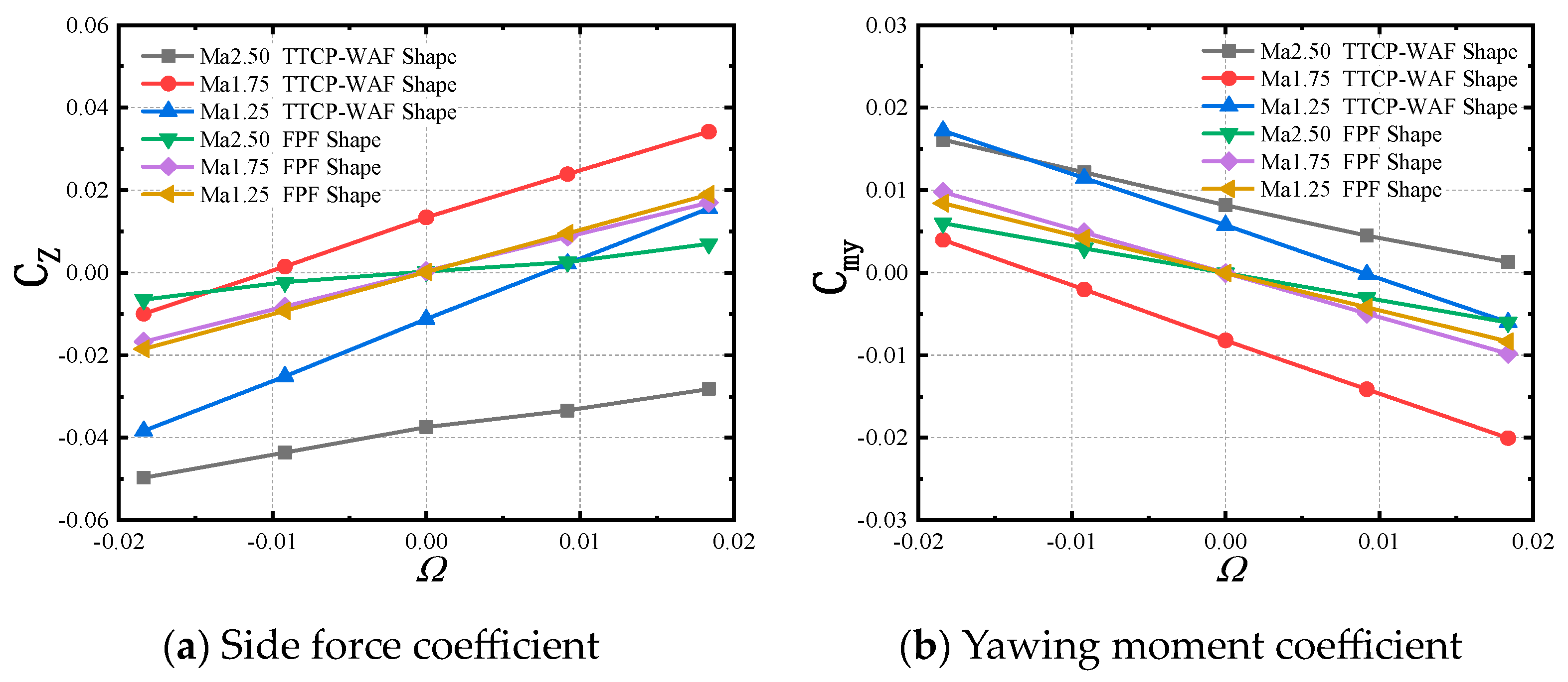
The side force and yawing moment of WAF and FPF missiles exhibit a good linear relationship with the dimensionless rotation rate. The difference lies in the WAF shape, which exhibits a self-induced side force and yawing moment. For WAF missiles, the static force/moment is of the same order of magnitude as the force/moment induced by rotation; hence, both are crucial aspects that cannot be overlooked in research and design.
(2)
There are two main reasons for the generation of time-averaged static side force and yawing moment on the wrap-around-fin missile: flow compression and expansion caused by the convex and concave surfaces resulting from the curvature of the tail fin, and the asymmetric body–fin disturbances caused by the curvature of the tail fin. Therefore, the curvature of the tail fin is the primary influencing factor.
(3)
The difference in the side force and yawing moment induced by rotation between the WAF and FPF shapes is very small. The two shapes have the same generation mechanism of this force/moment. The curvature of the tail fin has little effect on the side force and yawing moment induced by rotation.
(4)
The fins’ mechanisms of this force/moment are the change in the fins’ effective angle of attack caused by rotation and the force enhancement and attenuation caused by the body’s shielding effect. The body’s mechanisms of this force/moment are the Magnus effect of the forebody and the aerodynamic interference caused by the fins’ rotation. The contribution of the fins is approximately twice that of the body.
Limitations of this study: This research required a nonlinear aerodynamic model to describe the side force and yawing moment. However, cone movement was not considered in this study. The change rate of the attack angle and the cone movement rate were both assumed to be zero to simplify the analysis. Real flight processes are more complex than those studied here. Future research should address these factors for a more comprehensive understanding. Furthermore, this study did not investigate the specific impacts of factors such as the curvature, installation angle, and deflection angle of the tail fin. While the comparison between the wrap-around-fin and flat-plate-fin shapes can explain some phenomena, it is not comprehensive. It is necessary in future work to discuss the specific effects of these parameters on the tail fin.

Author Contributions

Conceptualization, J.L.; methodology, J.Y.; validation, Z.Y.; investigation, Z.Y.; data curation, Z.Y.; writing—original draft preparation, Z.Y.; writing—review and editing, J.L. and J.Y. All authors have read and agreed to the published version of the manuscript.

Funding

This research was supported by the National Natural Science Foundation of China (Grant No. 12472234).

Data Availability Statement

The result files for the numerical calculations are too large to be published online. If necessary, the data presented in this study can be made available on request by the corresponding author.

Conflicts of Interest

Author Jintao Yin was employed by the company Xi’an Modern Control Technology Research Institute. The remaining authors declare that the research was conducted in the absence of any commercial or financial relationships that could be construed as a potential conflict of interest.

Nomenclature

CmyCoefficient of yawing moment, My/qLrefSref
CpPressure coefficient, p / p
CzCoefficient of side force, Fz/qSref
dBody diameter, m
FZSide force, N
lBody length, m
LrefReference length, m
MaMach number
MyYawing moment,  N · m
p Freestream static pressure, Pa
qDynamic pressure,  ρ V 2 / 2
SrefReference area,πd2/4, m2
tRotation period, s
t Time step, s
T Freestream static temperature, K
V Freestream velocity, m/s
y+Non-dimensional wall distance
α Angle of attack, deg
θ Circumferential angle, deg
ρ Density, kg/m3
φRotation angle, deg
ωRotational rate, rad/s
Ω Dimensionless rotational rate,  φ ˙ d / 2 V

References

  1. Sturek, W.B.; Dwyer, H.A.; Kayser, L.D.; Nietubicz, C.J.; Reklis, R.P.; Opalka, K.O. Computations of Magnus Effects for a Yawed, Spinning Body of Revolution. AIAA J. 1978, 16, 687–692. [Google Scholar] [CrossRef]
  2. Mikhail, A.G. In-Flight Flexure and Spin Lock-in for Antitank Kinetic Energy Projectiles. J. Spacecr. Rocket. 1996, 33, 657–664. [Google Scholar] [CrossRef]
  3. Guidos, B.J.; Garner, J.M.; Newill, J.F.; Livecchia, C.D. Measured in-flight rod flexure of a 120-mm M829E3 kinetic energy (KE) projectile steel model. US Army Research Laboratory, Aberdeen Proving Ground, Adelphi, MD, USA. 2002; to be published. [Google Scholar]
  4. Martin, J.C. On Magnus Effects Caused by the Boundary-Layer Displacement Thickness on Bodies of Revolution at Small Angles of Attack. J. Aeronaut. Sci. 1957, 24, 421–429. [Google Scholar] [CrossRef]
  5. Fiebig, M. Laminar Boundary Layer on a Spinning Circular Cone in Supersonic Flow at a Small Angle of Attack; Cornell University: Ithaca, NY, USA, 1956. [Google Scholar]
  6. Sedney, R. Laminar Boundary Layer on a Spinning Cone at Small Angles of Attack in a Supersonic Flow. J. Aeronaut. Sci. 1957, 24, 430–436. [Google Scholar] [CrossRef]
  7. Jacobson, I.D. Contribution of a Wall Shear Stress to the Magnus Effect on Nose Shapes. AIAA J. 1974, 12, 1003–1005. [Google Scholar] [CrossRef]
  8. Platou, A.S. Magnus Characteristics of Finned and Nonfinned Projectiles. AIAA J. 1965, 3, 83–90. [Google Scholar] [CrossRef]
  9. Jenke, L.M. Experimental Roll-Damping, Magnus, and Static-Stability Characteristics of Two Slender Missile Configurations at High Angles of Attack (0 to 90 Deg) and Mach Numbers 0.2 through 2.5; Arnold Engineering Development Center; Arnold AFB: Tullahoma, TN, USA, 1976. [Google Scholar] [CrossRef]
  10. Jiasheng, W.; Xianming, J.; Ruisheng, M. Advances in the research for aerodynamic characteristics of Wrap-Around fins. Adv. Mech. 1995, 25, 102–113. [Google Scholar] [CrossRef]
  11. Jiasheng, W.; Xianming, J.; Wenxi, X. Self-Rolling Characteristics of Wrap Around Fin-Body Combinations. Trans. Beijing Inst. Technol. 1993, 2, 180–186. [Google Scholar]
  12. Eastman, D.; Wenndt, D. Aerodynamics of Maneuvering Missiles with Wrap-around Fins. In Proceedings of the 3rd Applied Aerodynamics Conference, Colorado Springs, CO, USA, 14–16 October 1985; American Institute of Aeronautics and Astronautics: Reston, VA, USA, 1985. [Google Scholar] [CrossRef]
  13. Abdullah, N.A.; Ismail, N.I.; Ismail, I.I.; Azami, M.H.; Nordin, N.H.; Sukindar, N.A.; Abidin, Z.Z.; Bakar, A.J.A.; Dani, N. Flow Behaviour Assessment of Smokey SAM Rocket Prototype. CFD Lett. 2021, 13, 42–56. [Google Scholar] [CrossRef]
  14. Wu, Y.; Huang, J.; Ji, B.; Song, L. Aerodynamic Shape Optimization of Subsonic/Supersonic Flows Integrating Variable-Fidelity Longitudinal Trim Analysis. Aerospace 2024, 11, 143. [Google Scholar] [CrossRef]
  15. Edge, H. Computation of the Roll Moment Coefficient for a Projectile with Wrap-around Fins. In Proceedings of the 31st Aerospace Sciences Meeting, Reno, NV, USA, 11–14 January 1993; American Institute of Aeronautics and Astronautics: Reston, VA, USA, 1993. [Google Scholar] [CrossRef]
  16. Abate, G.; Cook, T. Analysis of Missile Configurations with Wrap-around Fins Using Computational Fluid Dynamics. In Flight Simulation and Technologies; American Institute of Aeronautics and Astronautics: Reston, VA, USA, 1993. [Google Scholar] [CrossRef]
  17. Edge, H.L. Computation of the Roll Moment for a Projectile with Wrap-around Fins. J. Spacecr. Rocket. 1994, 31, 615–620. [Google Scholar] [CrossRef]
  18. Dahlke, C.W. A Review and Status of Wrap-Around Fin Aerodynamics. In Tenth Navy Symposium on Aeroballistics; Naval Surface Weapons Center: Dahlgren, VA, USA, 1975; Volume 1, pp. 279–324. [Google Scholar]
  19. Dahlke, C.W.; Flowers, L.D. The Aerodynamic Characteristics of Wrap-Around Fins, Including Fold Angle at Mach Numbers from 0.5 to 3.0; Army Missile Research, Development and Engineering Laboratory: Adelphi, MD, USA, 1974. [Google Scholar] [CrossRef]
  20. Tilmann, C.P.; Buter, T.A.; Bowersox, R.D.W. Characterization of the Flowfield near a Wrap-Around Fin at Mach 2.8. J. Aircr. 1998, 35, 868–875. [Google Scholar] [CrossRef]
  21. Zhang, G.Q.; Yu, S.C.M.; Schlüter, J. Aerodynamic Characteristics of a Wrap-around Fin Rocket. Aircr. Eng. Aerosp. Technol. 2016, 88, 82–96. [Google Scholar] [CrossRef]
  22. Yuwei, X.; Jie, L. Rolling Characteristics Investigation on Missile with Wrap-around Fins. J. Proj. Rocket. Missiles Guid. 2015, 35, 127–132. [Google Scholar] [CrossRef]
  23. Song, Q.; Yang, S.X.; Xu, Y.; Wang, F. Numerical simulation on aerodynamic characteristics of rolling rocket with Wrap Around Fins. J. Solid. Rocket. Technol. 2008, 31, 552–554+560. [Google Scholar]
  24. Wentao, Z.; Sijiang, C. Numerical analysis of aerodynamic characteristics of free-rotating wraparound fins projectile. J. Harbin Inst. Technol. 2023, 55, 113–122. [Google Scholar]
  25. Roe, P.L. Characteristic-Based Schemes for the Euler Equations. Annu. Rev. Fluid. Mech. 1986, 18, 337–365. [Google Scholar] [CrossRef]
  26. Menter, F.R. Two-Equation Eddy-Viscosity Turbulence Models for Engineering Applications. AIAA J. 1994, 32, 1598–1605. [Google Scholar] [CrossRef]
  27. Rivera, C.A.; Heniche, M.; Bertrand, F.; Glowinski, R.; Tanguy, P.A. A Parallel Finite Element Sliding Mesh Technique for the Simulation of Viscous Flows in Agitated Tanks. Int. J. Numer. Methods Fluids 2012, 69, 653–670. [Google Scholar] [CrossRef]
  28. Steijl, R.; Barakos, G. Sliding Mesh Algorithm for CFD Analysis of Helicopter Rotor–Fuselage Aerodynamics. Int. J. Numer. Methods Fluids 2008, 58, 527–549. [Google Scholar] [CrossRef]
Figure 1. A schematic diagram of the sliding mesh technique.
Aerospace 11 00765 g001
Figure 2. The geometric parameters and coordinate system.
Aerospace 11 00765 g002
Figure 3. A schematic diagram of the computational domain partition.
Aerospace 11 00765 g003
Figure 4. The mesh topology structures of the two shapes.
Aerospace 11 00765 g004
Figure 5. The schematic and mesh topology structure of the ANF.
Aerospace 11 00765 g005
Figure 6. A comparison of the time-averaged CZ and Cmy between the simulations and experiments.
Aerospace 11 00765 g006
Figure 7. Results of grid independence validation.
Aerospace 11 00765 g007
Figure 8. Results of time-step independence validation.
Aerospace 11 00765 g008
Figure 9. The time-averaged side force and yawing moment of the two shapes (α = 10°).
Aerospace 11 00765 g009
Figure 10. The time-averaged side force and yawing moment of the two shapes (α = 15°).
Aerospace 11 00765 g010
Figure 11. The transient side force and yawing moment coefficient of the WAF missile.
Aerospace 11 00765 g011
Figure 12. Contour map of the pressure distribution in the midsection of the tail fin (Ma = 2.5, x/L = 0.9).
Aerospace 11 00765 g012
Figure 13. The static side force and yawing moment characteristics of the two shapes (Ma = 2.5 and α = 15°).
Aerospace 11 00765 g013
Figure 14. The ratio of the additional force and moment to the static force and moment of the FPF.
Aerospace 11 00765 g014
Figure 15. The static side force and yawing moment curves for the tail fins and body (Ma = 2.5, α = 15°).
Aerospace 11 00765 g015
Figure 16. The contour map of the pressure distribution in the midsection of the tail fin (Ma = 2.5, α = 15°, φ = 45°, and x/L = 0.9).
Aerospace 11 00765 g016
Figure 17. The contour map of the pressure coefficient distribution near the windward surface of the tail fin at roll angles of 20° and 70°.
Aerospace 11 00765 g017
Figure 18. The vorticity contour maps of the two shapes at a roll angle of 45°.
Aerospace 11 00765 g018
Figure 19. The vorticity contour maps of the two shapes at roll angles of 20° and 70°.
Aerospace 11 00765 g019
Figure 20. The vorticity contour maps at the x/L = 0.9 section.
Aerospace 11 00765 g020
Figure 21. The pressure coefficients at different cross-sections of the body (Ma = 2.5, α = 15°, and φ = 45°).
Aerospace 11 00765 g021
Figure 22. The side force and yawing moment induced by the rotation rate.
Aerospace 11 00765 g022
Figure 23. The side force and yawing moment coefficients induced by the rotation rate.
Aerospace 11 00765 g023
Figure 24. The pressure coefficient difference between the rotating and static states within the midsection of the WAF (x/L = 0.9).
Aerospace 11 00765 g024
Figure 25. The pressure coefficient difference between the rotating and static states within the midsection of the FPF (x/L = 0.9).
Aerospace 11 00765 g025
Figure 26. The side force coefficient over a quarter rotation for the WAF and FPF.
Aerospace 11 00765 g026
Figure 27. The yawing moment coefficient over a quarter rotation for the WAF and FPF.
Aerospace 11 00765 g027
Figure 28. The pressure coefficient variation induced by the rotation rate at different cross-sectional positions of the missile body (φ = 0°).
Aerospace 11 00765 g028
Figure 29. The pressure coefficient variation induced by the rotation rate on the surface of the WAF missile (φ = 45°).
Aerospace 11 00765 g029
Table 1. Grid and time-step configuration for verification cases.
CaseLongitudinalCircularSpanwiseStep Size (s)Total Cells (Million)
A33916823T/144013.3
B43121430T/144024.7
C26913418T/14407.20
D33916823T/72013.3
E33916823T/288013.3
Disclaimer/Publisher’s Note: The statements, opinions and data contained in all publications are solely those of the individual author(s) and contributor(s) and not of MDPI and/or the editor(s). MDPI and/or the editor(s) disclaim responsibility for any injury to people or property resulting from any ideas, methods, instructions or products referred to in the content.

