Article

Numerical Investigation on Electromagnetic Scattering Characteristics of Circulation Control Wing Surface

1
AVIC Chengdu Aircraft Industrial (Group) Co., Ltd., Chengdu 610017, China
2
Key Laboratory of Aircraft Environment Control and Life Support, MIIT, Nanjing University of Aeronautics and Astronautics, Nanjing 211106, China
*
Author to whom correspondence should be addressed.
Aerospace 2024, 11(9), 781; https://doi.org/10.3390/aerospace11090781
Submission received: 19 July 2024 / Revised: 7 September 2024 / Accepted: 19 September 2024 / Published: 22 September 2024
(This article belongs to the Section Aeronautics)

Abstract

:
In order to study the effect of the circulation control technology on the electromagnetic scattering characteristics of the wing, a variety of low-scattering carrier models were designed based on the characteristics of the circulation control wing and the mechanical rudder surface. The radar scattering cross sections of the different models were then calculated by using the multilayer fast multipole algorithm. A comparative analysis of different models revealed that the use of the circulation control technique can reduce the front RCS level of the wing. Furthermore, the scaling effect was found to be more significant for the HH-polarised RCS at high frequency and the VV-polarised RCS at low frequency. The air source cavity structure of the jet system will increase the front and back RCS levels of the wing. Conversely, the back RCS level can be reduced by the oblique design of the jet nozzle. In the process of achieving attitude control, the wing applying the circulation control technique can significantly reduce its own front and side RCS levels, as well as the fluctuations of RCS levels throughout manoeuvres, in comparison to the usage of mechanical rudders. The findings of the study elucidate the scattering characteristics of the circulation control wing, which can serve as a reference for the stealth performance of unconventional layout aircraft.

1. Introduction

The stealth level of modern military equipment is a key factor in its combat effectiveness. Consequently, the reduction in radar cross section (RCS) is a primary focus of new aircraft stealth design [1,2,3,4]. The elimination of the horizontal and vertical tails, combined with a parallel design approach, can reduce the RCS to a lower level. The advantages of this design, including its aerodynamic efficiency, have led to its application in numerous military aircraft [5], including the U.S. B21 stealth bomber, the X-47B unmanned aerial vehicle (UAV) the French Neuron UAV, and China’s Attack-11 UAV, among others.
It should be noted that conventional mechanical flight control technology relies on ailerons and flaps to control the attitude of the aircraft [6], which results in frequent deflections of the rudder system, thereby compromising the stealth performance of the entire aircraft. In response to the further improvement of stealth performance requirements, active flow control technology has been applied to the aerodynamic control of aircraft. Among these technologies, circulation control has been the first to be widely verified on aircraft [7]. The fundamental principle of the circulation control technology is the introduction of high-pressure jets and Coanda surfaces at the trailing edge of the wing. The Coanda effect causes the high-speed airflow to continue along the wall until it separates, thereby modifying the flow field and aerodynamic forces outside the wing [8]. Wind tunnel testing on the circulation control airfoil using synthetic jet actuation was conducted by Itsariyapinyo et al. [9]. The optimum lift enhancement is observed to occur at frequencies on the order of the Strouhal number based on the Coanda surface diameter. The investigation on alleviation of airfoil gust load using circulation control technology was conducted by Li et al. [10]. The results demonstrate that circulation control technology, with its rapid frequency response characteristic, can effectively suppress lift disturbances caused by gusts in subsonic flows. Circulation control was shown to meet the pitch moment and response time requirements for flight stability control systems in the wind tunnel experiments of Zhang et al. [11].
Beginning with the study of the Coanda effect in the 1930s, circulation control technology has now entered the flight demonstration phase of research in various countries [12]. The joint project team formed by the University of Manchester and BAE Systems has developed different models and complexity of circulation control technology in the past two decades, such as the DEMON and MAGMA UAVs [13,14]. In 2020, the Nanjing University of Aeronautics and Astronautics (NUAA) achieved attitude control of a rudderless flying wing UAV using jet circulation control technology [15]. In 2021, the National Defence University (NDU) and the Military Academy of Sciences (MAAS) designed a trailing-edge jet roll control for a medium aspect ratio flying wing UAV and noted that this technology can improve the electromagnetic stealth characteristics of the aircraft in a typical angular domain [16]. The finite element method and boundary integral equation (FEM-BI) were proposed by Jin et al. [17] to calculate the electromagnetic scattering characteristics of complex seams. The investigation on scattering characteristics of the rudder structure of aircraft considering electromagnetic discontinuities seam was performed by Gu et al. [18], indicating that the structure of the rudder has a significant impact on the RCS of aircraft.
The review of the existing research on circulation control technology reveals a predominant focus on its impact on the aircraft’s manoeuvring and aerodynamic performance, and the research on the electromagnetic scattering characteristics of this technology has primarily aimed to enhance the stealth performance of the entire aircraft platform. However, it should be noted that the electromagnetic scattering level of aircraft with high stealth performance, such as those with a flying wing layout, is lower than that of traditional layout aircraft. Furthermore, the electromagnetic scattering characteristics of the wing manoeuvring surfaces are easily masked by the electromagnetic scattering from the tail nozzles [19] and other strong scattering sources in the backward direction. As a result, it is challenging to provide an accurate reflection of the electromagnetic scattering characteristics of the circulation control technology itself by studying the stealth performance change of the entire aircraft after the application of circulation control technology to the entire aircraft platform. In order to accurately assess the electromagnetic scattering characteristics of the circulation control wing (CC-wing), it is essential to conduct a dedicated study [20,21].
In this paper, we extract the main features of the mechanical rudder and CC-wing and design three low-scattering carriers for comparative analysis. The aforementioned carrier models retain the backward geometrical features of the mechanical rudder surfaces and CC-wing and restore their peripheral surface conditions in the loaded state as much as possible. This is performed in order to achieve the elimination of additional scattering caused by the truncated surfaces while avoiding the complex scattering effects of the whole aircraft. The electromagnetic scattering characteristics of the three models are performed based on the numerical results. The RCS variations during the dynamic processes of rudder deflection and wing roll are considered.

2. Computational Models and Numerical Methods

Firstly, according to the characteristics of the general mechanical rudder, a rectangular rudder is constructed, with a length of 600 mm, a width of 200 mm, and a maximum thickness of 40 mm. A low-scattering carrier is designed for the rudder (Figure 1b), with the leading edge of the carrier sharpened, the ribs transitioning smoothly to the trailing edge of the rudder, and the trailing edge swept back by an angle of 45°. The movable gap is maintained between the carrier and the rudder in order to restore the rudder to its original condition upon loading.
Next, in order to highlight the respective scattering characteristics of the CC-wing and the mechanical rudder, a basic low-scattering carrier is established for comparative analysis, as shown in Figure 1c. The gaps between the rudder and the carrier are cleared on the basis of the rudder carrier to ensure the surface is smooth and flat.
Finally, the CC-wing carrier is constructed. In order to prevent the introduction of additional scattering variables, the jet device and Coanda surface utilised in the circulation control technique are positioned at the trailing edge of the basic carrier with the intention of restoring the primary scattering characteristics of the CC-wing [22,23], as shown in Figure 1d. Figure 2 illustrates the internal structure of the CC-wing carrier. It comprises a high-pressure air source chamber located at the tail end, and the jet nozzle is closed when it is not in operation.
The terms “HH polarisation” and “VV polarisation” are used to describe the direction of the electric field. HH polarisation is defined as a horizontal electric field, while VV polarisation is defined as a perpendicular electric field to the horizontal plane. The azimuth angle of the electromagnetic wave is defined as 0° when it is illuminated from within the horizontal plane along the x-direction and 90° when it is illuminated from the y-direction. This is illustrated in Figure 3. Furthermore, the 0° direction of the model should be defined as the front, the 90° direction as the side, and the 180° direction as the back.
The Multilevel Fast Multipole Method (MLFMM) is a multilayer computational method that enables efficient numerical analyses of electromagnetic scattering problems from electrically large-size targets. It is currently one of the most widely used methods in RCS simulations [24,25,26]. The MLFMM method groups the subscatterers on the target surface. The coupling of subscatterers in neighbouring groups is obtained by direct computation, while the coupling of subscatterers in non-neighbouring groups is achieved by the group-to-group “transfer” process. A number of studies [21,27,28] have demonstrated that this calculation method is in good agreement with the results of microwave darkroom tests and can be used for the study of weak scattering sources such as slits.
The numerical calculations in this paper are performed using the Feko 2021 v1.0 software based on the MLFMM with far-field plane-wave irradiation conditions, treating the models as perfect electrical conductors. The frequencies of 3 GHz, 6 GHz, and 9 GHz are chosen as typical frequency points from the low-frequency band to the high-frequency band. The azimuth angle is defined as a range from 0° to 360° with a step size of 0.5°. The calculation type is monostatic RCS.
Given that X-band (8–12.5 GHz) represents the primary operating frequency band of airborne fire control radars and accounts for the largest proportion of radars targeting aircraft [2], the majority of contemporary stealth aircraft have been designed with X-band stealth performance in mind, while the other bands are considered to the extent feasible. In addition, due to the relatively subtle feature structure of the research object itself in this paper, its scattering situation changes relatively significantly at higher frequencies. Accordingly, to avoid the complexity of an excessive number of images in this paper, we primarily focus on the scattering curves at 9 GHz, and the low-frequency calculation results are exclusively illustrated in a table with mean value statistics.

3. Results and Discussion

3.1. The Electromagnetic Scattering Characteristics of Basic Carrier

From the RCS curves in Figure 4, it can be observed that the scattering peaks of the basic carrier in the VV polarisation are predominantly edge-winding from the side prisms and specular reflection from the trailing edge end face; in the HH polarisation, the scattering contribution is primarily from the side prisms. The mean RCS values presented in Table 1 demonstrate that the basic carrier exhibits a low scattering magnitude across all frequency bands. Furthermore, the scattering of the carrier itself is observed to be at a low level in both the front and back angular domains of interest. This provides a useful benchmark platform for the comparison and evaluation of the scattering characteristics of various carrier models.

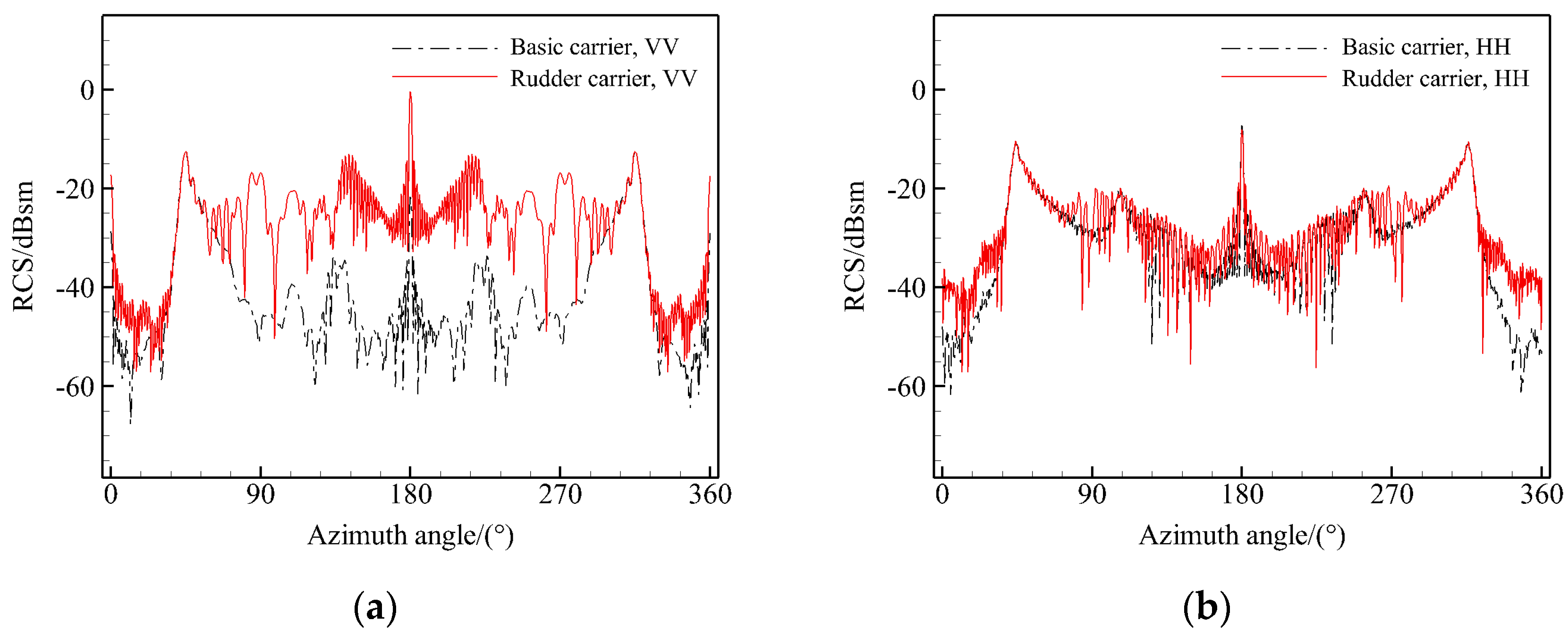
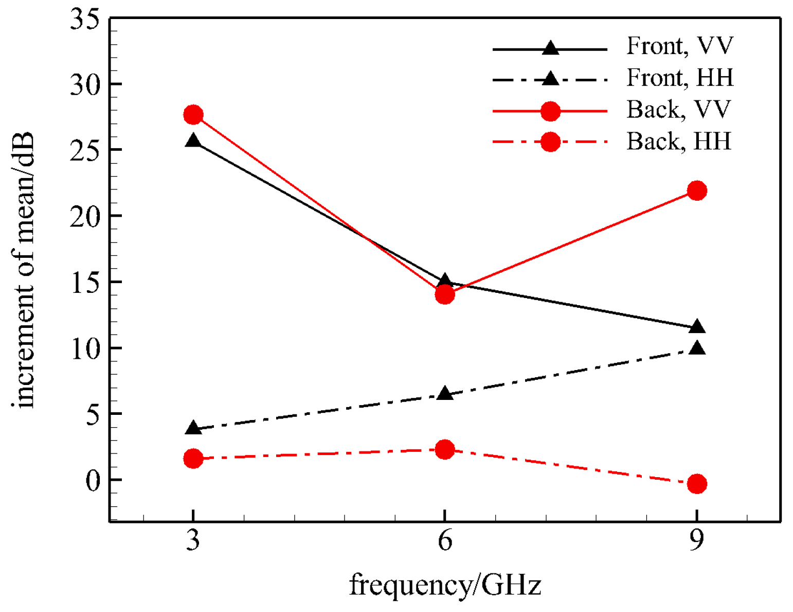
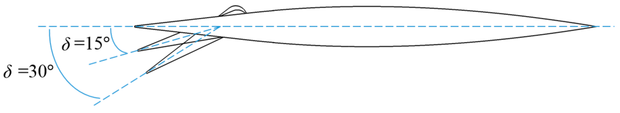
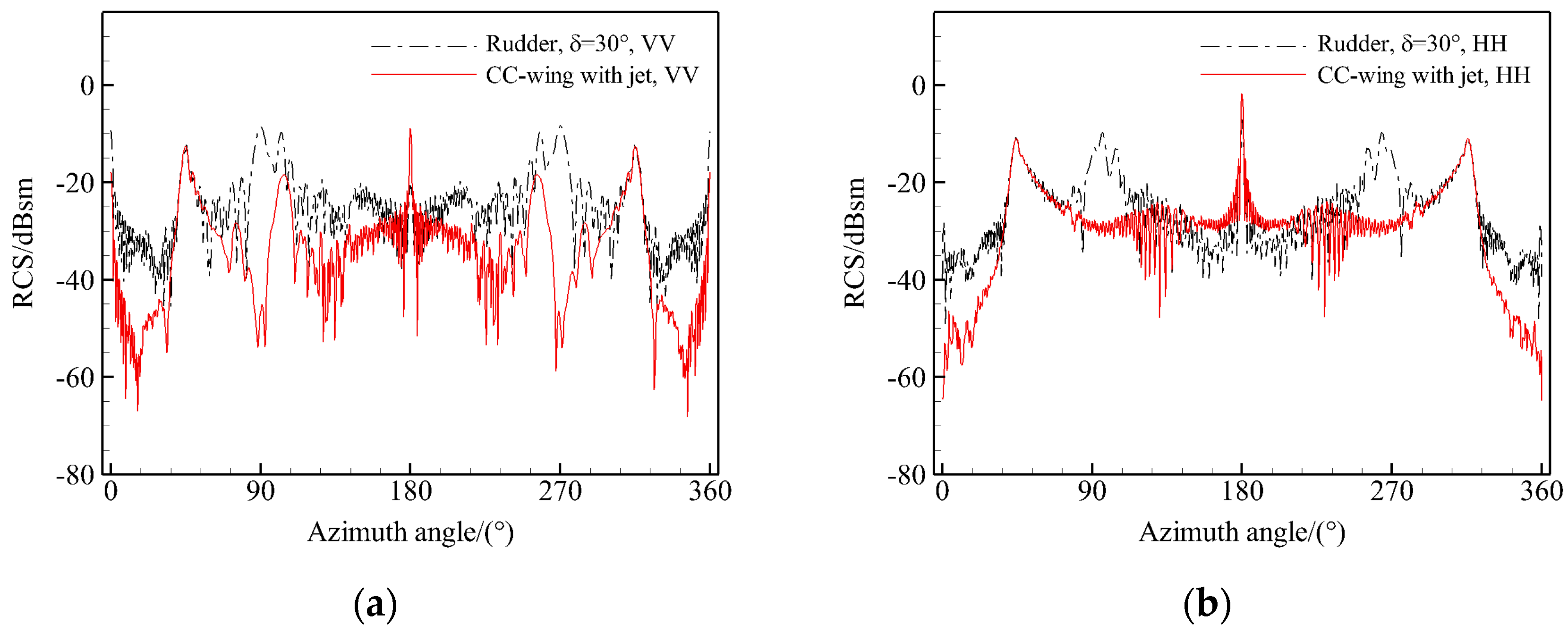
3.2. The Electromagnetic Scattering Characteristics of Rudder Carrier

A comparison of the scattering of the rudder carrier with that of the basic carrier allows the scattering level of the rudder itself to be determined.
The presence of the active gaps between the spreading and chordal directions results in a significant rise in the overall RCS profile of the rudder carrier in the VV polarisation, while the rise in the HH polarisation is relatively small, as illustrated in Figure 5. Figure 6 shows the RCS mean value increment of the rudder carrier in comparison with the basic carrier. It can be observed that the RCS mean value increment of the rudder carrier in the front ±30° range exhibits a decreasing trend with increasing frequency in the VV polarisation, while it exhibits an increasing trend with increasing frequency in the HH polarisation. Furthermore, the RCS mean increment in the back ±30° range is not linear with frequency, the rudder movable gap results in a larger RCS increment under the irradiation of the backward incident high-frequency electromagnetic wave.
It can be observed that the scattering characteristics of the mechanical rudder in the loaded state are contingent upon the polarisation characteristics. In particular, the rudder movable gap exhibits a more pronounced scattering increment in the VV polarisation than in the HH polarisation.

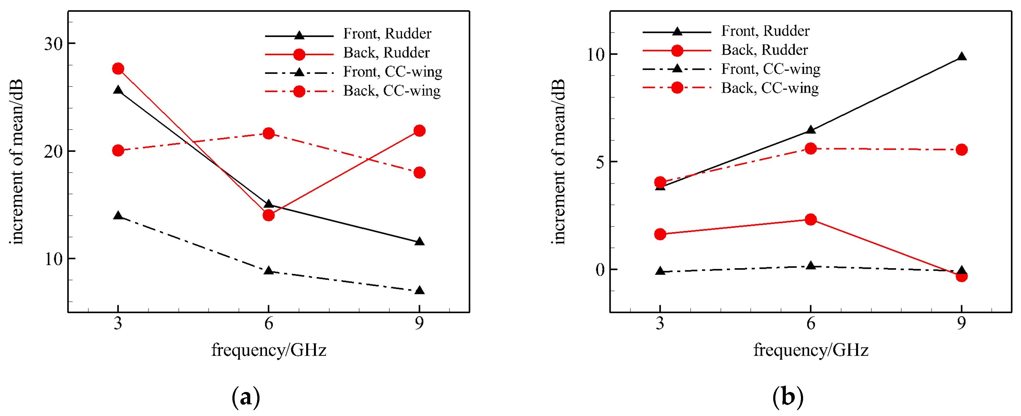
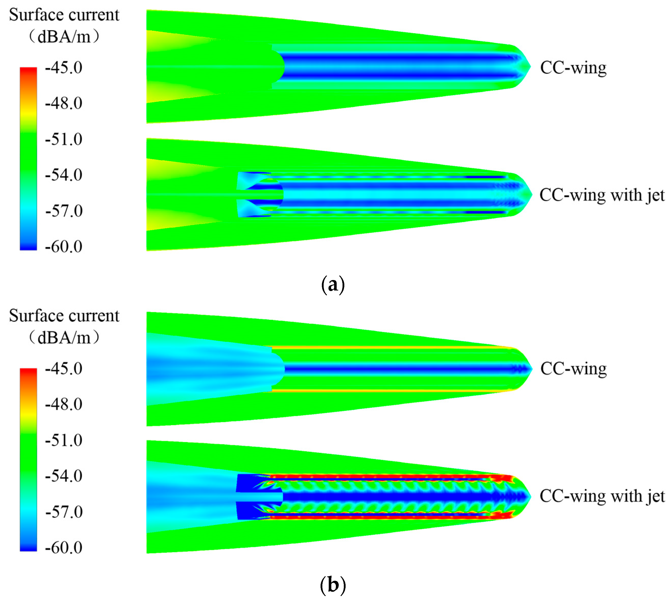
3.3. The Electromagnetic Scattering Characteristics of CC-Wing

3.3.1. Static Scattering Characterization

A comparison of the scattering changes of the CC-wing carrier with those of the basic carrier platform and the rudder carrier allows for the assessment of the scattering changes that occur after the rudder trailing edge end face is changed to a jet nozzle and Coanda surface.
In the event that the circulation control system is inoperative, the jet nozzle is closed, and the overall RCS curve of the CC-wing carrier under VV polarisation is significantly reduced in comparison to that of the rudder carrier in the majority of angular domains. Furthermore, the mean value of the side ±30° RCS is reduced by up to 15.10 dB at high frequencies. In contrast, the scattering curve under HH polarisation exhibits a decrease in the front direction and the side direction, while it is elevated in the back direction in the larger angular domain range, as illustrated in Figure 7.
Figure 8 illustrates the RCS mean increment of the CC-wing carrier and the rudder carrier in comparison to the basic carrier. It can be observed that in HH polarisation, the scattering contribution from the jet nozzle and surface in the front direction is less than that from the rudder gap, while that in the back direction is greater than that from the rudder gap. Furthermore, with the increase in frequency, the difference in the scattering increment is observed in the front RCS mean, and a reduction in the CC-wing can reach 9.94 dB at high frequency. In VV polarisation, the front RCS mean increment of the CC-wing is consistently lower than that of the rudder at all frequencies. However, the difference in the RCS mean increment between the two decreases with the increase in frequency and only increases by 3.94 dB at high frequencies. Meanwhile, the substantial alteration in the profile of the wing trailing edge resulting from the circulation control technique has led to a notable divergence in the characteristics of the two models in terms of the change in the back RCS level in response to the frequency of the incident radar wave.
In the operational state of the circulation control system, the jet nozzle is open, allowing electromagnetic waves to enter the cavity structure within the nozzle. A comparison of the RCS curves of the two states of the CC-wing in Figure 9 reveals that the presence of the jet nozzle cavity primarily affects the scattering characteristics at VV polarisation. This is evidenced by the presence of a large RCS wave peak in the side direction, which affects the angular domain, and a clear oscillation of the RCS curves in the backward direction.
Upon analysis in conjunction with the surface current distribution, it can be seen that the presence of the jet cavity significantly alters the electromagnetic scattering characteristics of the wing tail. A comparison of the tail current distribution at an azimuth angle of 0° (Figure 10a) reveals that the cavity strengthens the surface currents on the outer wall surface of the nozzle and the Coanda surface. Figure 10b,c correspond to the two peak positions in the side direction, where the creeping wave truncation effect on the outer wall surface of the nozzle is stronger and the currents are more concentrated at an azimuthal angle of 75°. Whereas at an azimuthal angle of 105°, the electromagnetic wave can directly illuminate part of the inner wall of the cavity, leading to further enhancement of the surface currents on the Coanda surface, which results in a significant enhancement of its RCS level. Table 2 also demonstrates that the mean RCS values in the front and side directions exhibit an increase with the rise in incident electromagnetic wave frequency. The enhancement of the scattering levels in the front and back directions brought by the cavity is more significant at high frequencies, and the enhancement of the mean RCS value in the side direction can reach up to 10.83 dB at high frequencies. When electromagnetic waves are incident in the backward direction, as illustrated in Figure 10d, more waves can enter the cavity structure and undergo multiple reflections inside the cavity before returning. This leads to an obvious oscillation on the radar cross-section (RCS) curve near the azimuthal angle of 180°. It is important to note that, due to the slanted surface of the jet nozzle designed in this study, a portion of the electromagnetic wave enters the cavity and is no longer returned along the original path after multiple reflections. This results in the mean value of its back RCS decreases by 4.42 dB. This effect is gradually weakened with the decrease in the frequency of the incidence of the electromagnetic wave.
It can be observed that the jet cavity employed in the circulation control technique exerts a more pronounced influence on the RCS level of the wing when subjected to high-frequency radar waves. Its distinctive tail structure serves to enhance the side and front VV-polarised RCS of the wing, while the back RCS level can be mitigated through the implementation of an appropriate design. To further reduce the side RCS level during manoeuvre, wave-absorbing materials can be utilised for the inner wall of the jet chamber, or wave-absorbing grills can be installed at the nozzle.

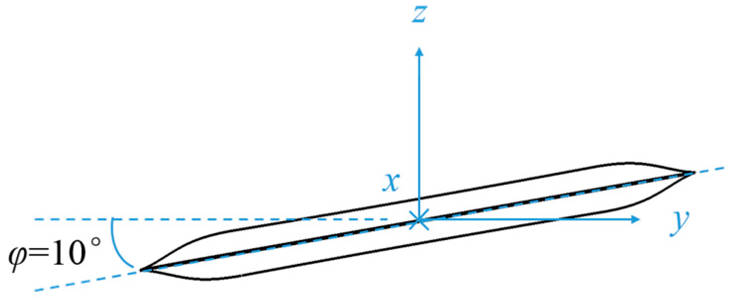
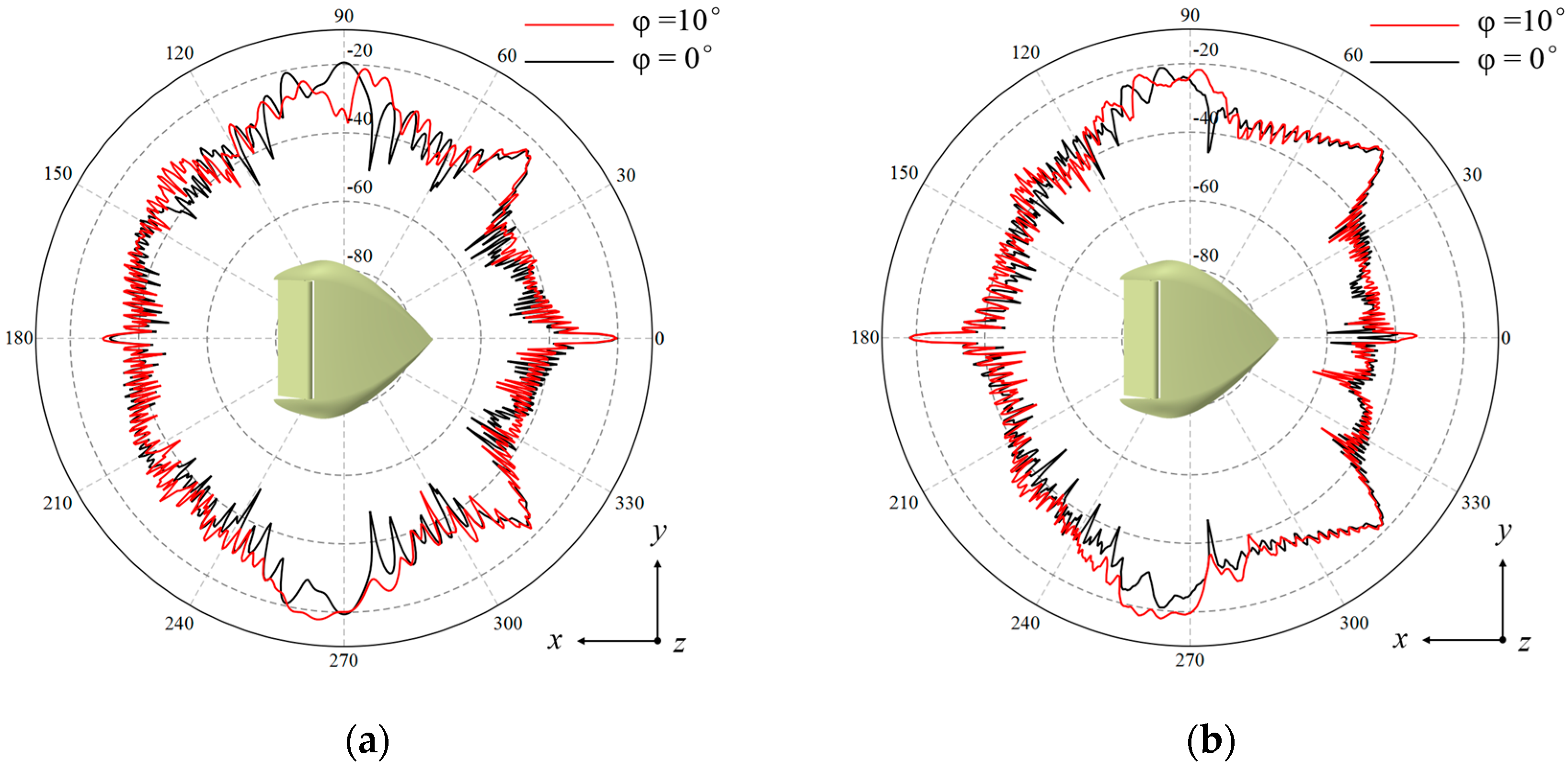
3.3.2. Dynamic Scattering Characterization

During the dynamic process of aircraft attitude adjustment, the mechanical rudders will be deflected, and the wing will also roll, resulting in a change in the RCS characteristics from those observed in a static state [16,29]. In order to evaluate the impact of the circulation control technique on the RCS level of the wing during attitude changes, a comparison is made between the RCS calculations of the mechanical rudder carrier with pitch angle δ and roll angle φ and those of the CC-wing carrier with the jet nozzles open. As evidenced by the findings of the preceding chapters, minor alterations to the structure of the model result in considerably more pronounced shifts in the electromagnetic scattering characteristics when subjected to high-frequency electromagnetic radiation. Consequently, the primary research frequency in this chapter is 9 GHz.
Firstly, the impact of rudder deflection is assessed in situations where the roll angle φ = 0. This analysis employs a graphical representation of the mechanical rudder deflection, as shown in Figure 11. A comparison of the mean RCS values of different models at high frequency in Table 3 reveals that the mean RCS values of the deflected rudder carrier are increased in both the front and side directions for different polarizations and enhanced with the increase in the deflection angle. However, the mean RCS value of the VV polarization in the back direction is decreased and further reduced with the increase in the deflection angle.
This change in the scattering situation is due to the fact that the direction of specular reflection at the trailing edge is deflected with the rudder and the illuminated area of the forward incident electromagnetic wave increases, resulting in a gradual decrease in the back RCS and an enhancement of the front RCS as the angle increases. It can also be seen from the comparison of the RCS curves in Figure 12 that the scaling of the front and side RCS values of the CC-wing is very significant compared to the deflected rudder, with the average front RCS value being scaled down by 12.09 dB (HH polarisation) and the average side RCS value being scaled down by 11.14 dB (VV polarisation).
Furthermore, the variation in scattering situations at a roll angle of 10° is comparatively analysed, and the roll angle of the airfoil is schematically illustrated in Figure 13. From an examination of the variation of the curves in Figure 14 and Figure 15, it can be observed that both the mechanical rudder and the CC-wing demonstrate a reduced impact on the back RCS as a result of changes in roll angle. However, both exhibit an elevated front horizontally polarised RCS level. The optimisation of the stealth performance of the trailing edge structure by the circulation control technique is readily constrained when the aircraft undergoes a roll operation.
It is worth noting that the side electromagnetic scattering characteristics of the mechanical rudder change considerably after the carrier model is rolled over. As the rudder slit is readily obscured by the carrier edge, the RCS levels of the rudder surface with varying deflection angles exhibit a fluctuating pattern. The mean value data in Table 4 reveals that the side RCS mean value in the -y direction is elevated to a greater extent than that in the +y direction. This suggests that the slit scattering on the ascending side is more susceptible to being obscured by the fuselage than the slit on the descending side. Nevertheless, the variation rule of the RCS mean value of the CC-wing is essentially identical on both sides, which suggests that the circulation control technique can effectively address the issue of a significant discrepancy in the side RCS level resulting from the aircraft’s roll operation.
The preceding analyses demonstrate that the aircraft’s dynamic process of attitude adjustment is facilitated by the circulation control technology, which prevents damage to the stealth performance of the wing caused by rudder deflection. Additionally, this technology enhances the RCS level fluctuation of the wing due to the frequent deflection of the rudder, which is of paramount importance for the control of the aircraft’s stealth level.

4. Conclusions

In this paper, the electromagnetic characteristics of the circulation control wing are investigated by simulation method, and a variety of low-scattering carrier models are established according to the scattering characteristics of different models, and the scattering changes of the wing applied with the circulation control technology are obtained by comparison. The following conclusions have been drawn:
(1)
The rudder movable gap of the traditional mechanical rudder surface primarily enhances the VV polarisation RCS of the wing. Conversely, the use of the circulation control technology can reduce the front RCS level of the wing, with a more pronounced reduction observed for the HH polarisation RCS at high frequency and the VV polarisation RCS at low frequency.
(2)
The Coanda surface utilised in the circulation control alters the contour of the trailing edge of the wing, which will consequently exert a detrimental influence on the rearward RCS level of the wing. In addition, the cavity structure of the high-pressure air source of the jet system will result in an increase in the front and back RCS levels of the wing. However, the back RCS level can be reduced by employing a bevelled design of the jet nozzle.
(3)
In the dynamic process of aircraft attitude adjustment, the circulation control technology can significantly reduce the front and side RCS levels of the wing in comparison to the wing that realises attitude control through rudders deflection. Furthermore, it can improve the issue of large differences in side RCS levels caused by wing roll and reduce the fluctuation of RCS levels in the dynamic process.
In general, in the unconventional layout aircraft where the attitude can only be controlled by the frequent manoeuvres of the ailerons and flaps, the overall reduction in RCS brought about by the use of the circulation control technique instead of the mechanical rudder is considerable. In the future, the use of wave-absorbing materials for the inner wall of the jet chamber or the installation of wave-absorbing grills at the nozzles may be considered as a means of further reducing the side RCS level of the wing during manoeuvres.

Author Contributions

Conceptualization, D.W. and W.D.; methodology, P.C.; software, P.C.; validation, D.W.; formal analysis, W.D.; investigation, H.L.; resources, P.C.; data curation, H.L.; writing—original draft preparation, D.W.; writing—review and editing, D.W.; visualization, D.W.; supervision, P.C.; project administration, W.D. All authors have read and agreed to the published version of the manuscript.

Funding

This research received no external funding.

Data Availability Statement

Data are contained within the article.

Conflicts of Interest

Authors Dechen Wang, Peng Cui and Wei Du were employed by the company AVIC Chengdu Aircraft Industrial (Group) Co., Ltd. The remaining author declares that the re-search was conducted in the absence of any commercial or financial relationships that could be construed as a potential conflict of interest.

References

  1. Kohin, M. Scatter reducing step: Theory and measurements. IEEE Trans. Antennas Propag. 1996, 44, 896–901. [Google Scholar] [CrossRef]
  2. Sang, J.H. Aircraft Stealth Technology; Aviation Industry Press: Beijing, China, 2015. [Google Scholar]
  3. Shi, C.G.; Dong, J.; Zhou, J.J.; Wang, F. Overview of aircraft radio frequency stealth technology. Syst. Eng. Electron. 2021, 43, 1452–1467. [Google Scholar]
  4. Ji, J.Z.; Huang, P.L.; Ma, Y.P.; Zhang, S.J. Stealth Principle; Beihang University Press: Beijing, China, 2018. [Google Scholar]
  5. Miller, D.N.; Williams, D.; Warsop, C.; Smith, D.R. NATO AVT-239 task group: Approach to assess prospects of active flow control on a next-gen tailless aircraft. In Proceedings of the AIAA SCITECH 2019 Forum, San Diego, CA, USA, 7–11 January 2019. [Google Scholar]
  6. Hoholis, G.; Steijl, R.; Badcock, K. Circulation control as a roll effector for unmanned combat aerial vehicles. J. Aircr. 2016, 53, 1875–1889. [Google Scholar] [CrossRef]
  7. Warsop, C.; Crowther, W.J. Fluidic flow control effectors for flight control. AIAA J. 2018, 56, 3808–3824. [Google Scholar] [CrossRef]
  8. Wang, D.C.; Du, W.; Sun, J.H.; Liu, H. Numerical simulation of ground-effect wing with front engine blowing. In Proceedings of the 6th China Aeronautical Science and Technology Conference, Jiaxing, Zhejiang, China, 26–28 September 2023. [Google Scholar]
  9. Itsariyapinyo, P.; Sharma, R.N. Experimental study of a NACA0015 circulation control airfoil using synthetic jet actuation. AIAA J. 2022, 60, 1612–1629. [Google Scholar] [CrossRef]
  10. Li, Y.H.; Qin, N. Airfoil gust load alleviation by circulation control. Aerosp. Sci. Technol. 2020, 98, 105622. [Google Scholar] [CrossRef]
  11. Zhang, L.; Huang, Y.; Zhu, Z.L.; Gao, L.H. Virtual flight test of pitch and roll attitude control based on circulation control of tailless flying wing aircraft without rudder. Chin. J. Aeronaut. 2023, 36, 52–62. [Google Scholar] [CrossRef]
  12. Smith, D.; Dickey, E.; VonKlein, T. The ADVINT Program. In Proceedings of the 3rd AIAA Flow Control Conference, San Francisco, CA, USA, 5–8 June 2006; AIAA: Reston, VA, USA, 2006; pp. 2006–2854. [Google Scholar]
  13. Buonanno, A. Aerodynamic Circulation Control for Flapless Flight Control of an Unmanned Air Vehicle. Ph.D. Thesis, Cranfield University, Bedfordshire, UK, 2009. [Google Scholar]
  14. Fielding, J.P.; Mills, A.; Smith, H. Design and manufacture of the DEMON unmanned air vehicle demonstrator vehicle. Proc. Inst. Mech. Eng. Part G J. Aerosp. Eng. 2010, 224, 365–372. [Google Scholar] [CrossRef]
  15. Sun, Q.B.; Shi, Z.W.; Geng, X.; Wang, L.S.; Zhang, W.Y. Attitude control of flying wing aircraft without control surface based on active flow control. Acta Aeronaut. Astronaut. Sin. 2020, 41, 124080. [Google Scholar]
  16. Shao, S.; Guo, Z.; Jia, G.W.; Yin, P.; Hou, Z.X.; Zhang, L.P. Roll control study of flying wing based on trailing-edge jet at wide speed rang. J. Natl. Univ. Def. Technol. 2022, 44, 101–115. [Google Scholar]
  17. Jin, J.M.; Volakis, J.L. TE scattering by an inhomogeneously filled aperture in a thick conducting plane. IEEE Trans. Antennas Propag. 1990, 38, 1280–1286. [Google Scholar] [CrossRef]
  18. Gu, Y.R.; Chen, S.S.; Gao, Z.H.; Zhou, L. Investigations on electromagnetic scattering characteristics of aircraft rudder considering electromagnetic discontinuities. Proc. Inst. Mech. Eng. Part G J. Aerosp. Eng. 2023, 237, 3696–3708. [Google Scholar] [CrossRef]
  19. He, Y.B.; Yang, Q.Z.; Gao, X. Comprehensive optimization design of aerodynamic and electromagnetic scattering characteristics of serpentine nozzle. Chin. J. Aero. 2021, 34, 118–128. [Google Scholar] [CrossRef]
  20. Ma, R.B.; Ai, J.Q.; Cui, L.; Zhang, Y. Geometric modeling and electromagnetic scattering characteristics analysis of aircraft control surface slot. Telecomm. Eng. 2022, 62, 336–341. [Google Scholar]
  21. Zhang, W.R.; Ai, J.Q.; Wang, J. Electromagnetic scattering characteristics analysis of trailing edge of a trapezoidal wing. Telecomm. Eng. 2021, 61, 242–247. [Google Scholar]
  22. Allan, B.G.; Jones, G.S.; Lin, J.C. Reynolds-averaged Navier-Stokes simulation of a 2-D circulation control wind tunnel experiment. In Proceedings of the 49th AIAA Aerospace Sciences Meeting, Orlando, FL, USA, 4–7 January 2011. [Google Scholar]
  23. Englar, R.J.; Jones, G.S.; Allan, B.G.; Lin, J.C. 2-D circulation control airfoil benchmark experiments intended for CFD code validation. In Proceedings of the 47th AIAA Aerospace Sciences Meeting, Orlando, FL, USA, 5–8 January 2009. [Google Scholar]
  24. Song, J.; Lu, C.C.; Chew, W.C. Multilevel fast multipole algorithm for electromagnetic scattering by large complex objects. IEEE Trans. Antennas Propag. 1997, 45, 1488–1493. [Google Scholar] [CrossRef]
  25. Senior, T.B.A.; Volakis, J.L. Scattering by gaps and cracks. IEEE Trans. Antennas Propag. 1986, 37, 744–750. [Google Scholar] [CrossRef]
  26. Crispin, W.J., Jr.; Maffett, A.L. Estimating the radar cross section of a cavity. IEEE Trans. Aerosp. Electron. Syst. 1970, 6, 672–674. [Google Scholar] [CrossRef]
  27. Huang, P.; Liu, Z. Research on electromagnetic scattering characteristics of slits on aircraft. Acta Aeronaut. Astronaut. Sin. 2008, 29, 675–680. [Google Scholar]
  28. Sang, J.H.; Zhang, Z.B.; Wang, S. Research on the radar cross section of weak scatterers on stealth vehicle. Adv. Aeronaut. Sci. Eng. 2012, 3, 257–262. [Google Scholar]
  29. Yue, K. Static and Dynamic RCS Characteristics of Combat Aircraft; Beihang University Press: Beijing, China, 2016. [Google Scholar]
Figure 1. Computational comparison model: (a) Rudder model; (b) Rudder carrier; (c) Basic carrier; (d) CC-wing carrier.
Aerospace 11 00781 g001
Figure 2. The cross-sectional view of the CC-wing carrier.
Aerospace 11 00781 g002
Figure 3. The definition of the direction of incidence of electromagnetic waves.
Aerospace 11 00781 g003
Figure 4. RCS curve of the basic carrier (9 GHz).
Aerospace 11 00781 g004
Figure 5. Comparison of RCS curves of the rudder carrier and basic carrier: (a) VV, 9 GHz; (b) HH, 9 GHz.
Aerospace 11 00781 g005
Figure 6. RCS mean value increment for the rudder carrier compared to basic carrier.
Aerospace 11 00781 g006
Figure 7. Comparison of RCS curves of CC-wing carrier and rudder carrier: (a) VV, 9 GHz; (b) HH, 9 GHz.
Aerospace 11 00781 g007
Figure 8. RCS mean increment of the CC-wing carrier and rudder carrier compared to the basic carrier: (a) VV; (b) HH.
Aerospace 11 00781 g008
Figure 9. Comparison of RCS curves of CC-wing carriers in non-operating/operating states: (a) VV, 9 GHz; (b) HH, 9 GHz.
Aerospace 11 00781 g009
Figure 10. Surface current distribution in the vicinity of the trailing edge of CC-wings for inoperative/operational states: (a) VV, 9 GHz, azimuth = 0°; (b) VV, 9 GHz, azimuth = 75°; (c) VV, 9 GHz, azimuth = 105°; (d) VV, 9 GHz, azimuth = 180°.
Aerospace 11 00781 g010aAerospace 11 00781 g010b
Figure 11. Mechanical rudder deflection schematic.
Aerospace 11 00781 g011
Figure 12. Comparison of RCS curves of CC-wing carrier with jet and rudder carrier with 30° of deflection: (a) VV, 9 GHz; (b) HH, 9 GHz.
Aerospace 11 00781 g012
Figure 13. Schematic of wing roll angle.
Aerospace 11 00781 g013
Figure 14. Comparison of RCS curves at different roll angles for a mechanical rudder with δ = 30°: (a) VV, 9 GHz; (b) HH, 9 GHz.
Aerospace 11 00781 g014
Figure 15. Comparison of RCS curves for CC-wing at different roll angles: (a) VV, 9 GHz; (b) HH, 9 GHz.
Aerospace 11 00781 g015
Table 1. Mean RCS values for basic carrier.
Frequency/GHzPolarizeRCS Mean Value/dBsm
Front ±30°Back ±30°Over 360°
3VV−41.58−39.99−24.69
HH−33.16−19.27−18.81
6VV−44.07−38.92−26.28
HH−40.71−21.97−21.24
9VV−43.48−37.71−27.59
HH−46.08−23.36−22.85
Table 2. RCS mean increment when jet nozzle is open compared to when it is closed.
Frequency/GHzPolarizeMean Value Increment/dB
Front ±30°Back ±30°Side ±30°
3VV1.931.180.75
HH0.03−0.040.01
6VV2.340.749.28
HH−0.650.01−0.13
9VV3.85−4.4210.83
HH−0.100.090.02
Table 3. RCS mean increment of CC-wing carrier and deflected rudder carrier compared to undeflected rudder carrier ( φ = 0).
ModelPolarizeMean Value Increment/dB
Front ±30°Back ±30°Side ±30°
rudder with δ = 15°VV1.20 −4.72 4.24
HH1.00 −1.00 2.84
rudder with δ = 30°VV8.67 −8.96 6.86
HH2.05 1.27 6.30
CC-wing with jetVV−0.68 −8.33 −4.27
HH−10.04 5.95 −2.76
Table 4. RCS mean increment for carrier models after roll angle change.
ModelPolarizeMean Value Increment/dB
Front ±30°Back ±30°Side ±30° (+y)Side ±30° (−y)
rudder with δ = 15°VV1.190.101.195.08
HH1.200.261.203.18
rudder with δ = 30°VV0.410.19−1.703.01
HH2.110.100.764.76
CC-wing with jetVV−0.20 0.55 −2.00 −1.79
HH2.19−0.041.661.61
Disclaimer/Publisher’s Note: The statements, opinions and data contained in all publications are solely those of the individual author(s) and contributor(s) and not of MDPI and/or the editor(s). MDPI and/or the editor(s) disclaim responsibility for any injury to people or property resulting from any ideas, methods, instructions or products referred to in the content.

