1. Introduction
SpaceFibre is a high data-rate communication protocol specifically designed for on-board data-handling space applications [
1]; its standardisation process by the European Cooperation for Space Standardization (ECSS) is at its final steps [
2] and is to be published in 2019 (ECSS-E-ST-50-11C). SpaceFibre protocol development has been promoted by the European Space Agency (ESA), which also developed the SpaceWire standard [
3], with SpaceFibre representing its evolution. SpaceWire is a full-duplex, low error rate line with low resources utilisation (5–8 Kgates) [
4] and a data-rate up to 400 Mbps. It has already been adopted in several ESA, National Aeronautics and Space Administration (NASA), and Japan Aerospace eXploration Agency (JAXA) missions, such as Rosetta, Mars-Express, Galileo and many others, making it a highly reliable solution. A wide set of COder-DECoders (CODECs) and routers is available on the market, both with Application Specific Integrated Circuit (ASIC) and Field Programmable Gate Array (FPGA) [
4], as well as a large choice of support equipment [
5]. SpaceWire also implements fault tolerance mechanisms that automatically switches from one link to another in case of failure with very small loss of information. The protocol itself has been designed for easier integration and to improve and promote equipment reuse across different missions, making it also a competitive choice in terms of costs.
SpaceWire adoption by different space agencies is therefore well motivated by the above considerations. Nevertheless, most recent applications require several Gbps data-rate, which cannot be achieved by a single SpaceWire node. In the near future, ESA upcoming missions (i.e., FLEX [
6] and BIOMASS [
7]) will mount Synthetic Aperture Radars (SARs) and hyper-spectral imagers which will require high speed on-board communication. In current missions, the lack of a standardised high-speed communication protocol led system integrators to adopt not optimised solutions such as WizardLink interfaces (not standardised) [
8] with customised protocol on top or more SpaceWire CODECs in parallel (more components, cables and connectors required). These reasons fostered SpaceFibre development, starting from the same basic concepts of SpaceWire and adding functionalities such as greater bandwidth, the concept of Virtual Channels (VCs), Quality of Service (QoS) and Fault Detection Isolation and Recovery (FDIR). In fact, SpaceFibre features meet the data-rate requirement of future missions: a single lane SpaceFibre link can achieve 6.25 Gbps bandwidth, which is necessary to support data-rate requirements of most advanced payloads. Other solutions are currently under evaluation by the space community to be selected as the next standardised high-speed communication protocol for space applications: in particular, RapidIO [
9] and TTEthernet [
10]. Nevertheless, the adoption of these solutions is not straight forward. In fact, even if they fulfil system requirements, they have several disadvantages: they are not based on an open ECSS standard, and the structure of the protocol itself is not developed aiming at optimisation for spacecraft usage but rather it is an adaptation of commercial technology to space requirements. SpaceFibre instead is based on an open standard and could be easily implemented by different entities, increasing its reliability. Even if the standard has not been released yet, a wide range of SpaceFibre based product is available, both as research project or commercial product, from CODEC Intellectual Property (IP) (from IngeniArs [
11], ESA [
12] and StarDundee [
1]) to routing switch (IngeniArs [
13] and StarDundee [
14]) and network simulator (IngeniArs [
15]). Moreover, it has been developed specifically for space applications, resulting in a highly optimised solution. However, in particular cases, SpaceFibre may also be over-specified. For instance, the data retry feature is not even removable in payloads characterised by streaming of large amount of data which do not contain critical information (i.e., high-resolution imaging payloads, where it is acceptable to lose data frames in case of upsets). Moreover, for small satellites and CubeSats [
16], where the size of components particularly matters, both high-speed interface and data processing unit are to be embedded in the same FPGA. An attempt to design a SpaceFibre endpoint with reduced complexity has already been presented in [
17], where an architecture to reduce area occupation has been proposed. Unfortunately, the lack of details on hardware configuration (i.e., target frequency, implementation of data scrambling, VCs size, etc.) combined with the fact that the standard significantly developed since 2014 makes it inappropriate to compare analytically our proposed implementation with the one contained in [
17].
The aim of the work presented in this paper is to propose a novel reduced architecture of the SpaceFibre protocol (from now R-SpaceFibre) that optimises resources utilisation at the expenses of reduced features. Furthermore, the proposed modifications to the standard are intended to be compatible with a fully compliant implementation of it. R-SpaceFibre has been realised starting from the IngeniArs SpaceFibre CODEC IP. Since the aim of this paper is to present a modified and reduced version of the SpaceFibre standard, the results presented are all referred to the same full SpaceFibre CODEC (from IngeniArs). The obtained resource reduction is then theoretically achievable also on other different implementations.
In
Section 2, architectural design choices for the development of R-SpaceFibre are presented focusing on the different protocol layers. In
Section 3, the hardware set-up chosen to validate R-SpaceFibre and to demonstrate interoperability with a SpaceFibre CODEC is described and resources utilisation results on different space-grade FPGAs are presented. In
Section 4, a possible use case of the R-SpaceFibre IP core is discussed. Finally,
Section 5 summarises the presented work and its outcomes.
2. R-SpaceFibre Design: Features and Trade-Offs
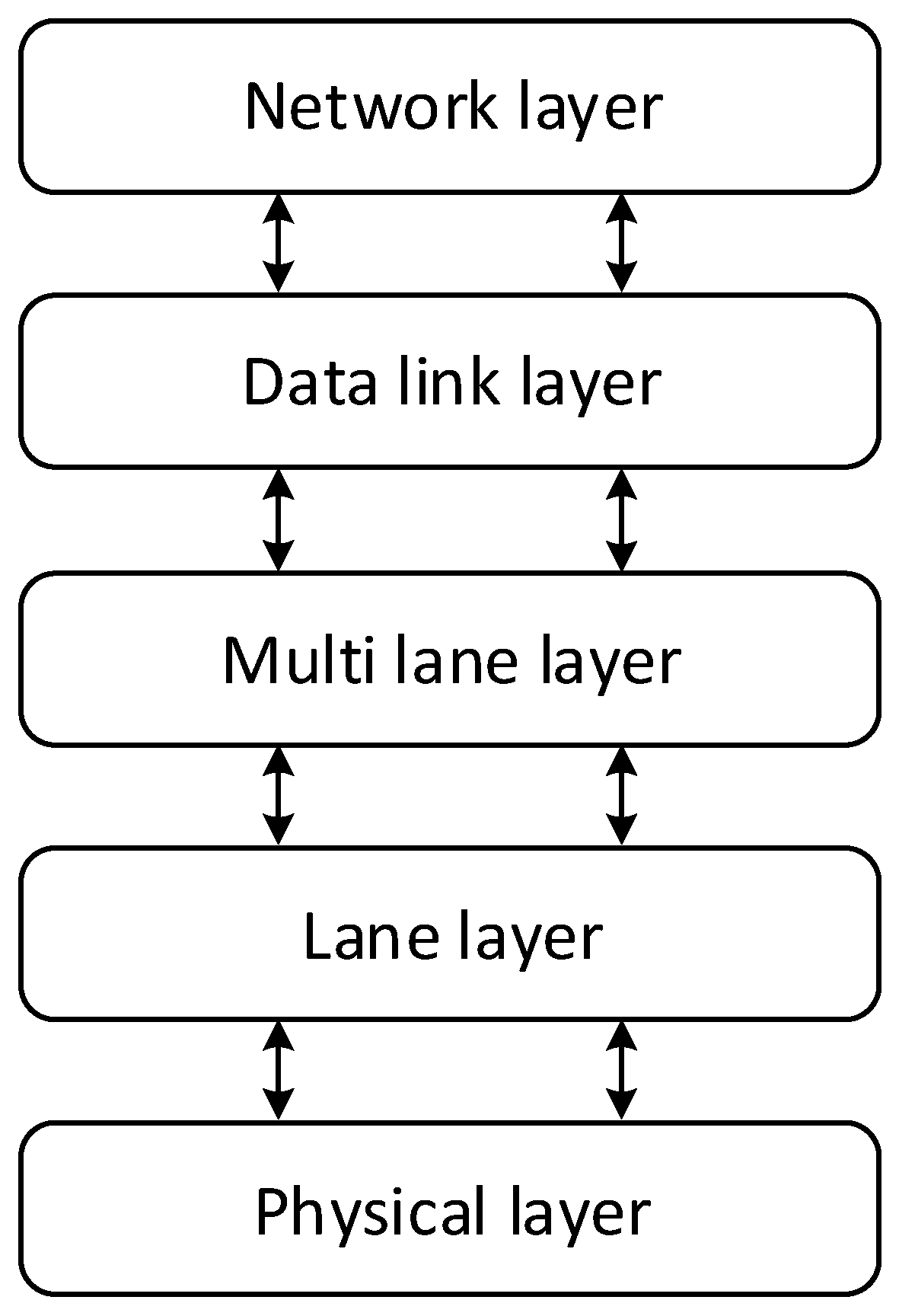
To understand the design choices made in the R-SpaceFibre development, it is necessary to briefly introduce the SpaceFibre protocol stack.
The stack is composed of five layers, as shown in
Figure 1:
The Network layer is responsible for transferring both data and broadcast messages through the SpaceFibre network.
The Data Link layer is responsible for the FDIR system that implements a retry mechanism to resend corrupted frames. Moreover, it handles independent flow of information through Virtual Channel Buffers (VCBs), and it manages the QoS, broadcast service and data scrambling.
The Multi lane layer is responsible for synchronising a link composed by more than 1 lane (up to 16). This is an optional layer.
The Lane layer is responsible for establishing the communication between two ends.
The Physical layer is responsible for serialising, transmitting, receiving and de-serialising data.
The Network layer has not been included in R-SpaceFibre design as it is realised as an optional upper layer, and it is not needed for point-to-point links. R-SpaceFibre indeed has been designed for satellites with stringent requirements in terms of size and volume. These satellites often mount a reduced number of devices and usually a single payload, thus point-to-point high-speed connections are definitively preferred against more complex network topologies. The Multi lane layer is not included as well: it allows increasing the maximum achievable data-rate and system reliability adding redundancy but requiring considerably more hardware resources [
18].
For this reason, the reference SpaceFibre IP cell of this study is composed only by the core layers: Data link, Lane and Physical Layer. Most of the architectural modifications aim at reducing the hardware resources in the Data link layer, which is the most complex layer in terms of area occupation [
19]. Some of its features are not essential to the core communication process, thus are removable from the design, accepting some performance degradation. Indeed, the Lane layer, which is responsible for initialising the link, and the Physical layer are fully compliant with the standard, as no significant optimisations are possible.
Schematic descriptions of both SpaceFibre and R-SpaceFibre Data link layers are presented in
Section 2.1 and
Section 2.2, in order to point out architectural innovations and shared features. The internal architectural description of each building block is not described as the aim of this work is to propose a high level architecture which saves resources employing a subset of the building block already present in a regular SpaceFibre interface. For a full description of the layer, please refer to the SpaceFibre standard [
2].
2.1. SpaceFibre Data Link Layer
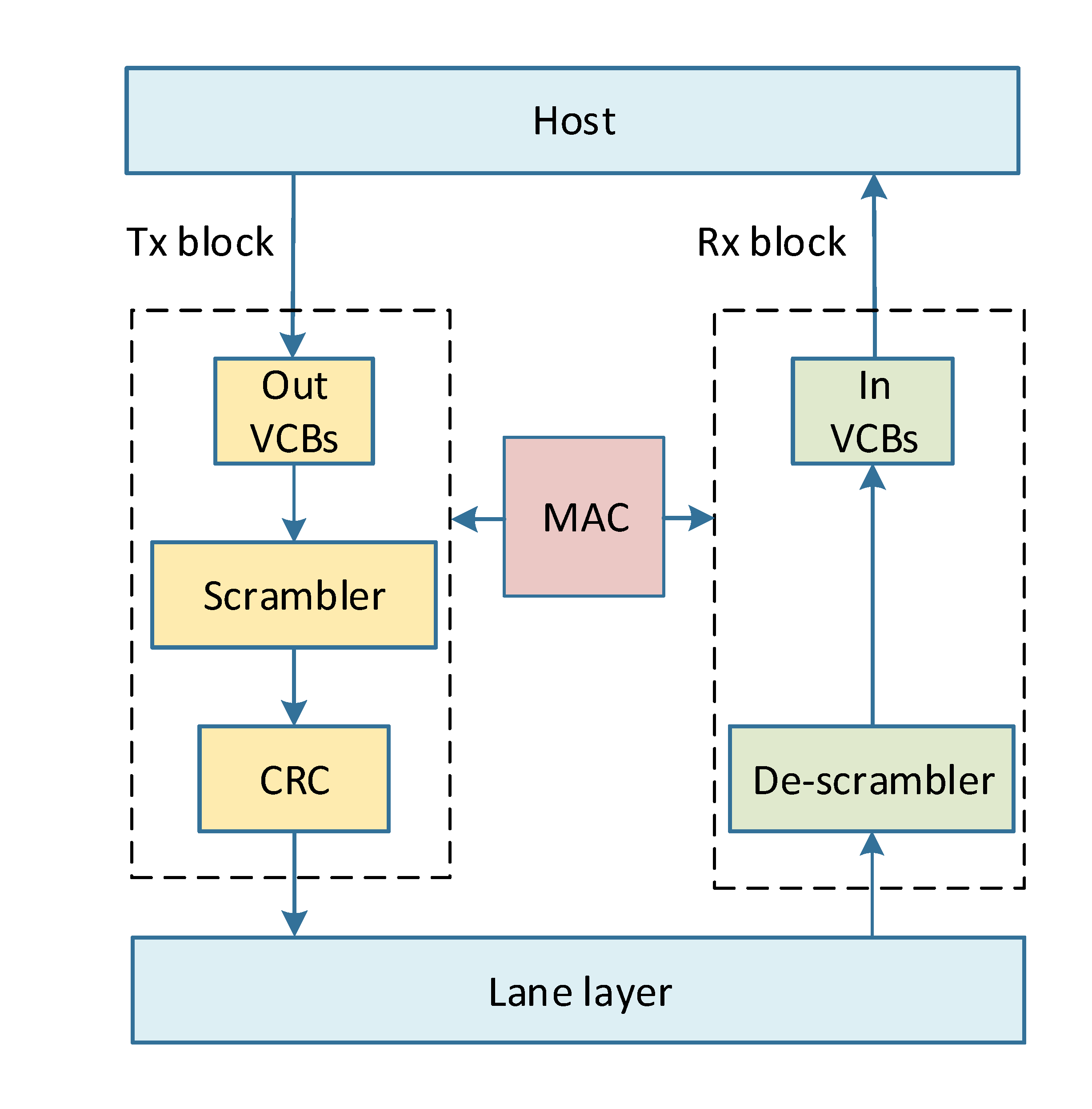
The Data link layer of a fully compliant version of the protocol is described in this paragraph, with reference to a simplified architectural block diagram shown in
Figure 2. It is composed by a Medium Access Controller (
MAC), a transmission block (
Tx Block) and a receiving block (
Rx Block).
The data interface with the host is realised trough VCs, both on the RX side (Out VCBs) and on the TX side (In VCBs). They allow handling independent flows of information across a single physical link. There are up to 32 different VCs available. A special interface is dedicated to broadcast (BC) messages, with one Rx buffer, Out Broadcast Channel Buffer (Out BCB), and one TX buffer, Input Broadcast Channel Buffer (In BCB).
The MAC is the core of the Data link layer: it manages data framing and it is responsible for synchronising the operations between transmitting and receiving side. Moreover, the MAC implements the QoS: it continuously schedules which VC shall send data based on different parameters such as priority and reserved bandwidth.
The Data link layer also implements retry buffers to resend data in the case the far-end of the link detects a communication error and asks for retransmission. The Retry Buffers block contains three buffers: the Data Retry Buffer, the Flow Control Token (FCT) Retry Buffer and the Broadcast Retry Buffer.
Data or BC are read out from the selected VC or from the corresponding Retry Buffer and framed appropriately. Then, data frame could be scrambled to reduce electromagnetic emissions and eventually the Cyclic Redundancy Check (CRC) [
20] block computes a numeric field to be added at the end of each data frame, broadcast message and control words that require it. The far-end will re-compute independently this value and will compare it with the received one, in order to detect accidental errors occurred during the communication process and promptly ask for retransmission of corrupted frames or control words.
Conversely, on the Rx side, received data frames, BC messages and control words are handled. First, CRC Check block controls the correctness of the CRC value embedded in received data. In the case of errors, a retry request is sent to the far-end. If no errors are detected, data frame may be de-scrambled and stored in the appropriate
In VCB, whereas broadcast messages are stored in the
In BCB. Control words are consumed for managing the communication process. For detailed information, please refer to the SpaceFibre standard [
2].
2.2. R-SpaceFibre Data Link Layer
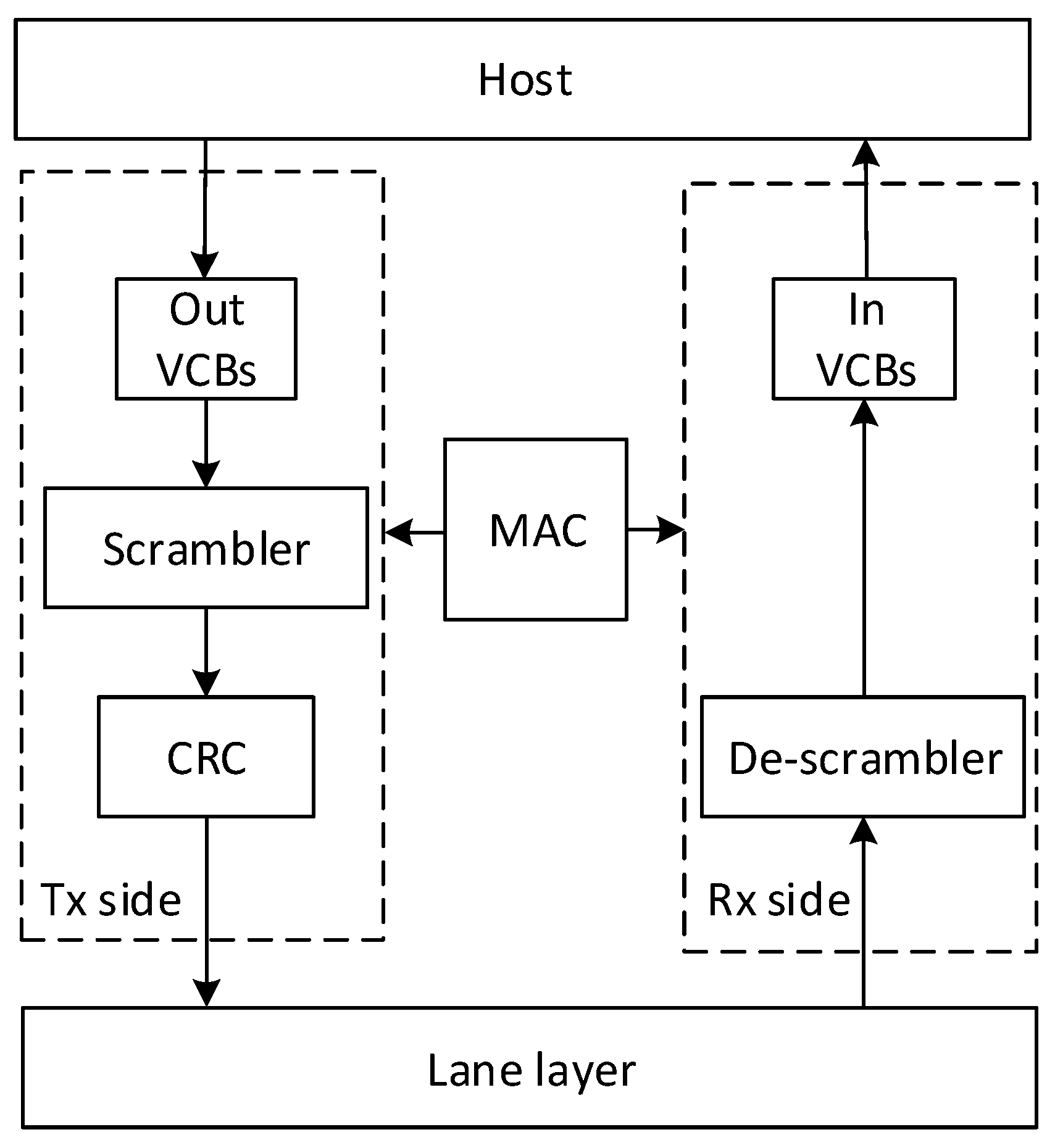
This section describes the proposed architecture of R-SpaceFibre Data link layer. A simplified architectural block diagram of the layer is shown in
Figure 3. R-SpaceFibre major innovation is the exclusion of the retry mechanism from the protocol stack. The first consequence is that none of the Data Retry Buffer, the Broadcast Retry Buffer or the FCT Retry Buffer has to be included in the R-SpaceFibre Data link layer, with consistent savings of logical resources. This comes at the price of no data-retry if an error occurs with consequent data loss. However, the system is designed to continue the communication process, and a corrupted datum is passed to the higher level of the protocol. In fact, target applications such as SAR imagers can withstand the corruption of a single bit or the loss of a data word. The SpaceFibre CODEC properly works with a maximum Bit Error Rate (BER) of 10
−5 [
11]. However, typical BERs for satellite applications are in the order of 10
−10, which is much lower than the worst case handled by the SpaceFibre protocol. The application system engineer will decide whether complexity reduction at the price of data retry removal is acceptable for their application, depending on link criticality, orbit (BER), etc.
R-SpaceFibre is designed mainly for point-to-point communication. For this reason, the broadcast service, responsible for sending short messages to all the nodes of a network, is unnecessary. Thus, In and Out BCBs have been excluded from the architecture. The removal of retry and broadcast services implies that also all QoS mechanisms (i.e., VCs scheduling and bandwidth reservation) become less complex, thus the MAC can be simplified.
The CRC Check block has been removed from the Rx Block: consequently, the IP core is no more able to signal to the far-end if received data frames or control words are corrupted. The near-end needs to acknowledge also corrupted data frames, so that compatibility with a full implementation of the standard at the far-end is maintained. More details about R-SpaceFibre compatibility with a full SpaceFibre interface are provided in
Section 2.3. On the contrary, the CRC on the Tx Block cannot be removed: it has to be maintained in order to be compatible with the SpaceFibre protocol. Indeed, a standard SpaceFibre endpoint always performs CRC check on received data frames and control words; without it, the CODEC would automatically consider all received data as corrupted. Nevertheless, the CRC block could be excluded from the Tx Block if the R-SpaceFibre just needs to communicate with R-SpaceFibre nodes. The proposed design includes optional data scrambling on both Tx and Rx side.
The SpaceFibre standard establishes that the number of VCs shall to be between 1 and 32. R-SpaceFibre can handle an arbitrary number of VCs, but, to reduce the impact on resource usage, the number of VCs shall be limited to one or two. In particular, by choosing to use only one VC the QoS is drastically reduced, together with the multiplexing logic between VCs and the lower part of the Data link layer. Both standard and literature [
17] suggest that the QoS could be completely eliminated in an implementation of just of one or two VCs, but this implies that babbling node protection is not provided [
2].
Finally, VCs dimension is set to be 256 data words, which is the minimum dimension according to the standard. In conclusion, the most relevant design changes in the R-SpaceFibre development are the removal of:
Retry buffers, from the Tx Block
Broadcast service, from the entire Data link Layer
CRC check block, from the Rx Block
Several QoS mechanism, from the MAC
2.3. Fault Tolerance and Compatibility with Full SpaceFibre Interfaces
R-SpaceFibre is meant to be used as lightweight high performance high speed link. It is a slightly modified version of the SpaceFibre protocol, fully interoperable with a SpaceFibre endpoint but compliant just to a subset of the SpaceFibre standard requirements, in order to reduce system complexity. When two Reduced SpaceFibre (R-SpFi) endpoints communicate together, no restrictions on protocol operations arise, also in the case of Single Event Upset (SEU) bit-flip errors happening on the link. The received corrupted packet will be handled at higher levels of the protocol, application dependent. However, it is possible to connect R-SpaceFibre and SpaceFibre endpoints. Coherent data transmission and reception is guaranteed, discarding received broadcast messages and ignoring retry requests. R-SpaceFibre is programmed to discard any retry request from a far-end. Consequently, if an error occurs during the transmission of a packet from full SpFi interface to a reduced SpFi endpoint, no retry request is given and the received corrupted packet is transmitted at the higher level of the protocol, where it will be handled according to the application requirements. Indeed, R-SpaceFibre has been designed for communication link involving payloads streaming large amount of data that do not contain safety-critical information. On the other hand, when a SEU occurs in the transmission of a packet from a R-SpFi interface to a full SpaceFibre interface, the second one will constantly try to ask for data retransmission, blocking the traffic on that Virtual Channel. This can be easily handled programming a reset interface to be given in order to re-establish the communication flow.
4. R-SpaceFibre Use Case Scenario: CubeSats
R-SpaceFibre combines high data-rate capability with small hardware resources occupation, accepting reduced performances in terms of error recovery. This innovative technology is a suitable solution for applications with relaxed requirements in terms of bit error rate and stringent requirement of size, volume and cost such as CubeSats. Indeed, this class of small spacecraft needs optimised on-board components. In this section, CubeSats features and applications are analysed pointing out why R-SpaceFibre represents a valuable solution for enhancing CubeSats data-rate capability at low cost of volume and price.
CubeSat is a class of nanosatellite (with a mass between 1 and 10 Kg) standardised by the California Polytechnic State University in 1999. They are made up of 10 cm × 10 cm × 10 cm units (1U) with a maximum weight of 1.33 Kg [
16] that could be assembled to compose larger satellites (i.e., 2U, 3U, 6U and 12U).
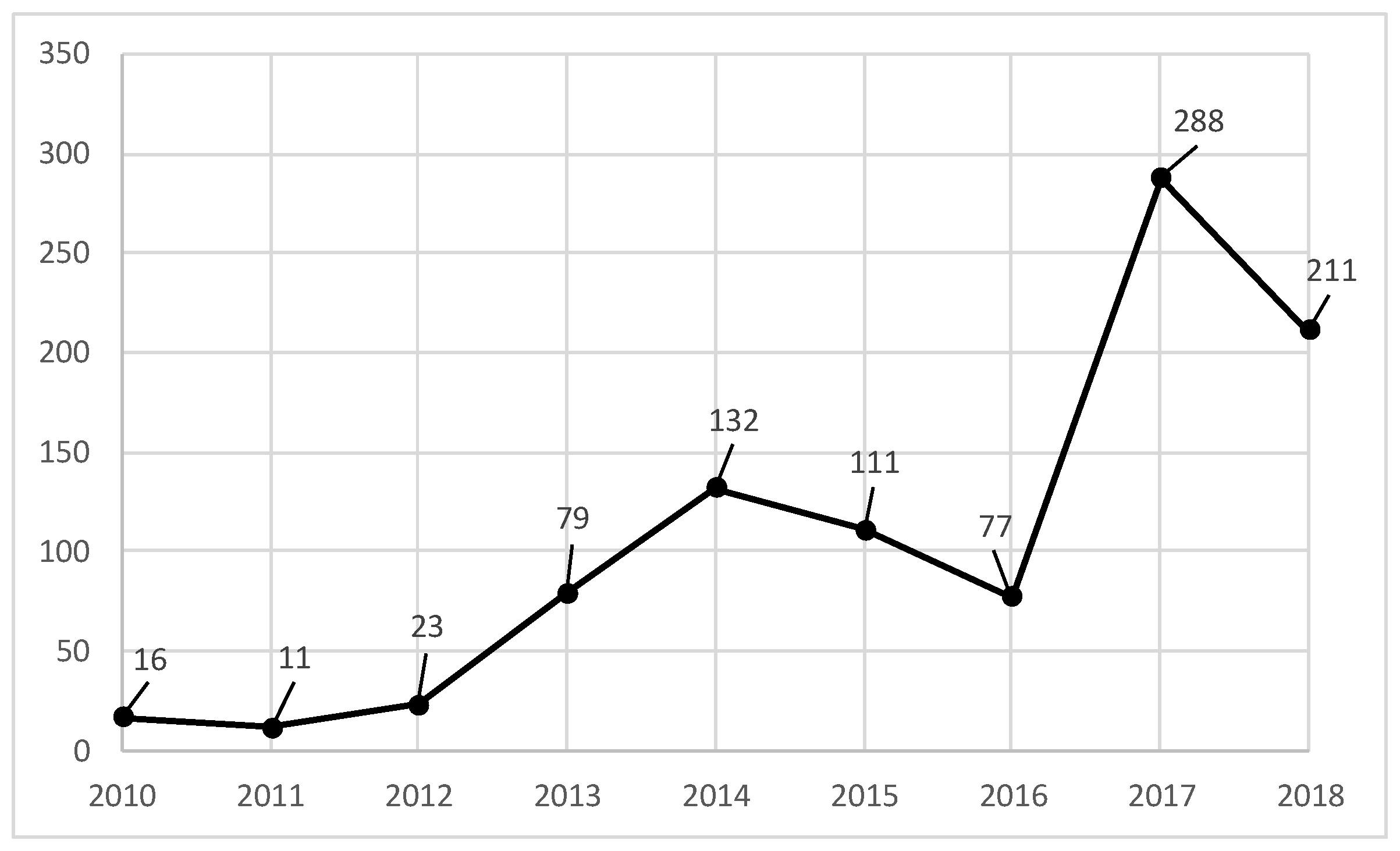
In the last few years, CubeSats have become more and more popular and the number of CubeSats launched into space per year is growing, as shown in
Figure 5. According to the CubeSat database of the St. Louis University [
23], 796 CubeSats had been launched as of 31 December 2018.
CubeSats, initially developed for educational purposes, despite their limitation in terms of mass and volume are emerging as important technological platforms, especially for Earth observation application, and represent a cost-effective and fast-to-launch solution [
24].
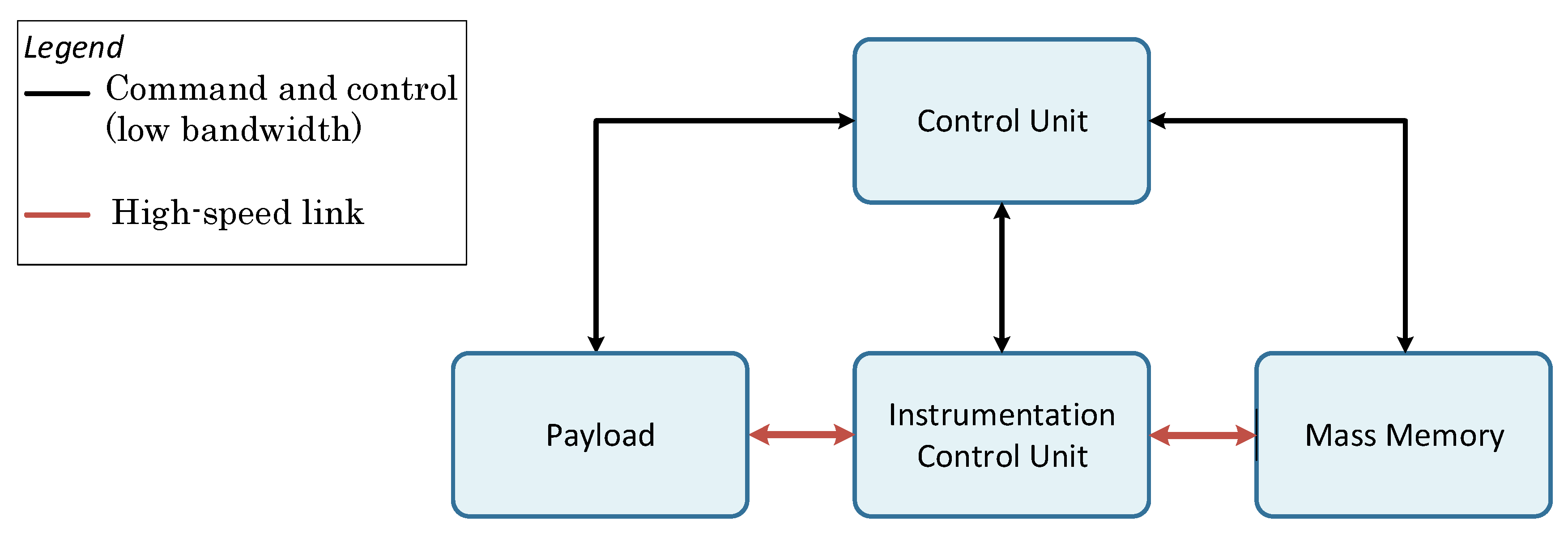
A possible architecture for CubeSat on-board electronics is shown in
Figure 6. The Control Unit manages and configures other units through command and control interfaces, characterised by low bandwidth and strict reliability constraints. The payload is connected through a high-speed link to an Instrumentation Control Unit that elaborates received data. Data are stored in a Mass Memory, which is connected as well through a high-speed link, waiting to be sent back to earth. Considering their limitation in terms of mass and volume, CubeSats cannot mount a great number of instruments and the data-handling subsystem is generally as simple as possible privileging point-to-point connections to more complex network topologies.
R-SpaceFibre may be a feasible solution for high-speed serial links in CubeSats data-handling subsystem, combining SpaceFibre cable mass reduction and performances with a small footprint on FPGA devices, which allows system designer to potentially fit it in FPGAs which share other tasks (i.e., the Instrument Control Unit, ICU). According to
Table 1, it is possible to implement two R-SpaceFibre interfaces (i.e., necessary to the ICU of
Figure 6) on a small footprint FPGA like the RTAX2000, employing only 32.36% of the total LUT, 28.46% of DFF and 12.50% of RAM with large part of the FPGA still available for other mission dependent features implementation. The same architecture implementing a regular SpaceFibre needs 54.22% of LUT, 48.46% of DFF and 37.5% of RAM, offering less possibility to integrate extra features on the same device. R-SpaceFibre could help to reduce the number of devices embedding more features on the same FPGA. It also reduces the overall electronic price, which represent a key advantage for low cost missions, such as CubeSats.
The state-of-the-art for rad-hardened CubeSat data-handling subsystem is the Sphinx Deep Space Command and Data Handling (CDH) board [
25] developed by the Jet Propulsion Laboratory (JPL) that will be mounted on the Lunar Flashlight [
26] and NEAScout missions [
27]. The Sphinx CDH has a mass of less than 200 g and may be housed in a 10 cm × 10 cm area, with a maximum power consumption of 7 W. Considering the communication interfaces, the Sphinx mounts four SpaceWire ports that have a maximum data-rate of 400 Mbps and seems not to be the ideal solution for increasing CubeSat data-rate capability: four separate interfaces require separate connectors and cables, which could represent an issue in volume contained systems such as CubeSats. Moreover, the overall data-rate is still below the one easily obtainable with one R-SpaceFibre interface. The Sphinx CDH interface and R-Spacefibre may be compared considering hardware resources needed to be implemented on a FPGA device.
Table 4 shows the results obtained for R-SpaceFibre and four SpaceWire interfaces realised, respectively, by IngeniArs [
28] and STAR-Dundee [
29] on a RTAX2000. The two communication interfaces need similar hardware resources, but R-SpaceFibre increases the achievable data-rate from 1.6 Gbps of the Sphinx SpaceWire solution to 1.8 Gbps and can be further improved to 3.125 Gbps implementing the design on higher performance FPGAs such as RTG4. Furthermore, R-SpaceFibre reduces cable volume and mass: considering state-of-the-art cables from Axon, the Sphinx requires four SpaceWire cables (one per port), whose weight is 42 g/m [
30] for a total of 168 g/m. On the other hand, R-SpaceFibre requires only one SpaceFibre cable, weighting 15 g/m [
31], achieving around 90% mass reduction, as shown in
Table 5.
Currently, CubeSat missions already plan to mount SAR and Interferometric SAR (InSAR) as payloads. Those instruments require data-rate in the order of Gbps, which is not easily targetable with state-of-the-art technology. For example, SRI International has prototyped the CubeSat Imaging Radar for Earth Science (CIRES), designed for a 6U CubeSat constellation [
32] and capable of a moderate resolution (25 m). Moreover, other present and future missions, such as Capella 1 [
33] and Iceye [
34], will mount SAR as payloads, while Intuition-1 [
35], HyperCube [
36] and Waypoint 1 [
37] will mount hyper-spectral imagers. On-board data-handling bandwidth of these missions is expected to be in the order of Gbps, falling in the operational range of R-SpaceFibre.
This brief analysis suggests that R-SpaceFibre may be a valid solution for on-board data handling of CubeSats mounting high resolution payloads in the near future: even if R-SpaceFibre performances are reduced compared to full SpaceFibre implementations, it allows significantly reducing the required hardware resources, combining high data-rate with other advantages proper for the SpaceFibre protocol.


