Article

A Novel Optimized Link-State Routing Scheme with Greedy and Perimeter Forwarding Capability in Flying Ad Hoc Networks

1
Department of Electrical Engineering, College of Engineering, Taif University, P.O. Box 11099, Taif 21944, Saudi Arabia
2
Center of Research and Strategic Studies, Lebanese French University, Kurdistan Region, Erbil 44001, Iraq
3
Pattern Recognition and Machine Learning Lab, Gachon University, 1342 Seongnamdaero, Sujeonggu, Seongnam 13120, Republic of Korea
4
Department of Computer Science and Mathematics, Faculty of Economic Studies, University of Finance and Administration, 10100 Prague, Czech Republic
*
Authors to whom correspondence should be addressed.
Mathematics 2024, 12(7), 1016; https://doi.org/10.3390/math12071016
Submission received: 22 February 2024 / Revised: 21 March 2024 / Accepted: 25 March 2024 / Published: 28 March 2024
(This article belongs to the Special Issue Blockchain and Internet of Things)

Abstract

:
A flying ad hoc network (FANET) is formed from a swarm of drones also known as unmanned aerial vehicles (UAVs) and is currently a popular research subject because of its ability to carry out complicated missions. However, the specific features of UAVs such as mobility, restricted energy, and dynamic topology have led to vital challenges for making reliable communications between drones, especially when designing routing methods. In this paper, a novel optimized link-state routing scheme with a greedy and perimeter forwarding capability called OLSR+GPSR is proposed in flying ad hoc networks. In OLSR+GPSR, optimized link-state routing (OLSR) and greedy perimeter stateless routing (GPSR) are merged together. The proposed method employs a fuzzy system to regulate the broadcast period of hello messages based on two inputs, namely the velocity of UAVs and position prediction error so that high-speed UAVs have a shorter hello broadcast period than low-speed UAVs. In OLSR+GPSR, unlike OLSR, MPR nodes are determined based on several metrics, especially neighbor degree, node stability (based on velocity, direction, and distance), the occupied buffer capacity, and residual energy. In the last step, the proposed method deletes two phases in OLSR, i.e., the TC message dissemination and the calculation of all routing paths to reduce routing overhead. Finally, OLSR+GPSR is run on an NS3 simulator, and its performance is evaluated in terms of delay, packet delivery ratio, throughput, and overhead in comparison with Gangopadhyay et al., P-OLSR, and OLSR-ETX. This evaluation shows the superiority of OLSR+GPSR.

1. Introduction

A flying ad hoc network (FANET) is a type of ad hoc network made up of unmanned aerial vehicles (UAVs). This network is rapidly progressing. UAVs have become a vital part of real-world applications, for example, wireless coverage, search and rescue, geographic mapping, and monitoring of smart products and transportation systems [1,2,3]. FANETs are a branch of mobile ad hoc networks (MANETs) and vehicular ad hoc networks (VANETs). In recent years, an attractive research area has been the participation of FANETs with other ad hoc networks, especially VANETs, to increase their efficiency and performance in smart transportation systems. In VANET, UAVs act as relay nodes to prevent frequent interruptions in communications between vehicles [4,5,6].
FANETs have specific features such as highly mobile nodes, low density, frequent changes in network topology, and low scalability. These features have led to challenging issues such as routing and reliable communications in FANET because the communication links are typically created and distorted quickly [7,8,9]. This leads to packet loss. These challenges attract the attention of many researchers. In the recent years, researchers have studied and investigated the existing routing protocols in MANETs and VANETs [10,11,12]. These protocols cannot make effective communications in FANETs and must be improved to obtain good performance in these networks because they ignore the specific features of FANET such as the high dynamic topology, highly mobile nodes, and limited energy resources. Hence, it is very challenging to develop a routing protocol that provides reliable communication in FANET [13,14,15].
In this paper, a novel optimized link-state routing scheme with greedy and perimeter forwarding capability called OLSR+GPSR is presented in flying ad hoc networks. In this scheme, OLSR is enhanced to reduce overhead and delay in the routing process. OLSR is a proactive routing protocol whose advantage is its sensitivity to changes in the network topology. When these changes occur in the network topology, OLSR updates routing tables stored in UAVs to maintain routes formed between network nodes. However, this method faces serious challenges such as highly unstable communication links in FANET because it is very difficult to access the new network topology. Therefore, it is difficult and time consuming to choose multi-point relays (MPRs) and calculate routing paths between all UAVs. Furthermore, discovered paths will often be invalid before use in the data transmission process. This issue imposes communication costs and a high delay to rebuild these paths in FANET. In contrast, GPSR works well in terms of delay and throughput and uses a unicast technique to send data packets to the destination. As a result, its overhead is low. These advantages are our main motivation for designing OLSR+GPSR, which merges OLSR and GPSR to improve the routing process in OLSR and fix its challenges in FANET. In this regard, OLSR+GPSR, unlike OLSR, removes two phases, namely the dissemination of topology control (TC) messages and the calculation of routing paths between all network nodes due to high communication overhead, and adds the greedy and perimeter forwarding phase to the routing process. In summary, the main innovations in OLSR+GPSR are as follows:
  • In OLSR+GPSR, a fuzzy system is provided to regulate the time period for broadcasting hello messages based on the two inputs, namely velocity and position prediction error. This fuzzy system causes the adaptability of the proposed method to FANET so that high-speed UAVs employ a shorter time interval to propagate hello messages, and low-speed UAVs apply a longer time period to disseminate hello messages in the network.
  • In OLSR+GPSR, unlike OLSR, MPR nodes are determined based on several metrics, including neighbor degree, node stability (based on velocity, direction, and distance), the occupied buffer capacity, and residual energy. This increases the stability of MPRs, improves energy efficiency, and decreases delay and communication overhead in FANET.
  • In OLSR+GPSR, two phases, namely TC message dissemination and route calculation in OLSR, have been deleted to reduce the overhead. Then, after the broadcast of hello messages and the selection of MPRs, the greedy and perimeter forwarding phase is started to find routing paths through MPR nodes, and data packets are sent to the destination.
The structure of the present paper includes the following sections: Section 2 presents the related works performed on this research subject. Section 3 explains both optimized link-state routing (OLSR) and greedy perimeter stateless routing (GPSR) in summary. Section 4 describes the network model in OLSR+GPSR. Section 5 expresses the proposed method in detail. Section 6 presents the evaluation results of OLSR+GPSR. Finally, Section 7 concludes this paper.

2. Related Works

Ref. [16] proposes a modified OLSR based on the position information of UAVs to choose MPRs efficiently. This method is compatible with the specific features of FANET, such as the high mobility of UAVs, frequent topology changes, and energy constraints. Moreover, this routing protocol does not rely only on the node connections as a standard to select MPRs but uses the estimated transmission counts (ETX) along with their position information and a weighted cost function based on residual energy and neighbor degree in the MPR selection process. In this scheme, ETX is improved based on the expiration time of links between UAVs. Note that based on this improved ETX criterion, this scheme does not select low-energy UAVs with high neighbor degrees as MPRs. In this scheme, when the estimated ETX related to a UAV is less than one and the value of its cost function (calculated based on residual energy and neighbor degree) is minimum, this UAV can be selected as an MPR node. The purpose of this method is to increase PDR and throughput and reduce latency and routing overhead. Simulation results indicate the superior performance of this protocol compared to P-OLSR and OLSR-ETX.
Ref. [17] introduces a routing protocol called P-OLSR to maintain communications between drones in FANET. P-OLSR uses GPS information to predict the positions of UAVs. Furthermore, this method is compatible with the rapid changes in the network topology and forms reliable multi-hop communications between UAVs to prevent path failures. In addition, P-OLSR has improved the formats of both control packets, namely the hello message and TC message. Spatial coordinates (longitude, altitude, height) related to each UAV are shared with other neighboring nodes to obtain the overall topology of FANET. Then, this scheme is compared with OLSR in flying ad hoc networks. Simulation results show that P-OLSR is significantly better than OLSR when frequent changes occur in the network topology.
Ref. [18] offers a new routing technique called the enhanced OLSR-ETX inspired by OLSR in FANETs. This algorithm is compatible with fast changes in the network topology and prevents path failures in the network. In enhanced OLSR-ETX, the main novelty is to use position information obtained from the global positioning system (GPS) to evaluate the expiration time of links between UAVs. It also pays attention to the residual energy of UAVs in the routing process. In addition, in this scheme, ETX is improved based on connection time and the residual energy of the nodes. Then, this improved ETX is considered for selecting MPRs, instead of the neighbor degree of UAVs in the original OLSR protocol. Therefore, if a UAV goes out of the communication range of the relevant UAV or has less energy than its other neighboring nodes, the enhanced OLSR-ETX does not select this UAV as an MPR. This method is implemented in NS3 and the results indicate its successful performance in terms of PDR, latency, and overhead compared to OLSR. In addition, the enhanced OLSR-ETX guarantees reliable communications between source and destination in FANET.
Ref. [19] provides a mobility-based weighted cluster routing scheme called MWCRSF to improve the performance of FANET. MWCRSF employs the sparrow search algorithm (SSA) and introduces a new SSA-based clustering algorithm to form clusters in the network. It considers several criteria such as the remaining energy, correlation degree, relative velocity, distance between each UAV and BS, and centrality for picking up the most suitable cluster heads in the network. Additionally, MWCRSF presents an efficient cluster maintenance algorithm to update clusters. To transmit data packets to BS in a timely and reliable manner, MWCRSF finds an optimal next-hop node with regard to link longevity, remaining energy, and the distance between UAVs and BS. Because of the use of skyline operators, MWCRSF makes multi-objective decisions, reduces the search area, and enhances efficiency when finding cluster heads in the clustering process and the next-hop node in the routing process. The simulation results state that MWCRSF has a better performance than other routing schemes in terms of cluster stability, energy efficiency, throughput, and network lifetime.
Ref. [20] provides an aerial greedy geographic routing algorithm (AGGR) in FANET. AGGR includes an adaptive hello strategy and a greedy forwarding technique based on the mobility information of UAVs. In this approach, UAVs are divided into two categories, namely active nodes and idle nodes. Then, AGGR determines the broadcast period of hello messages, related to active nodes based on their mobility information relative to their upstream UAVs, and the broadcast time of hello messages related to idle UAVs based on the relative mobility information of their neighboring UAVs. In addition, the greedy transmission process considers the relative mobility information of UAVs to increase the adaptability of AGGR to the highly dynamic network topology in FANET. In addition, it considers the time to enter the transmission area of destination as a criterion for selecting the next-hop UAV. The simulation results indicate that AGGR significantly reduces two problems, namely temporary communication blindness (TCB) and high path failures in FANET, and improves network performance.
Ref. [21] proposes an OLSR-based routing approach based on fuzzy logic called OLSR+ in flying ad hoc networks. In this scheme, UAVs use a distributed technique to find their neighbors. Additionally, in this step, real-time link duration is calculated using a new solution, which depends on link quality, distance, relative velocity, and direction. The next step introduces a fuzzy model to specify MPRs for each UAV. This model considers three fuzzy inputs, namely neighbor degree, link duration, and remaining energy, and if a UAV has more values of these three inputs than other neighboring UAVs, it gets a higher score than other UAVs in the MPR selection process and may be selected as an MPR. Then, OLSR+ makes some changes in the structure of the TC message and adds two new metrics, namely path energy and path longevity to this framework. In the last step, it obtains routing tables stored in the memory of UAVs based on the number of hops and these two new metrics (i.e., path longevity and energy). OLSR+ is run on NS3, and the results obtained from this process show that this routing scheme has an acceptable performance compared to G-OLSR and OLSR, except that it has high routing overhead.
Ref. [22] suggests a fuzzy routing technique in FANET. This technique designs an improved route discovery phase. It evaluates UAVs based on their remaining energy, direction, link quality, and stability to remove weak UAVs and find the most suitable relay nodes for broadcasting RREQs in the network. This reduces routing overhead and manages the flood of control messages disseminated for discovering new paths in the network. Then, a fuzzy system evaluates the discovered paths to choose routes with short delay and low hops. In the last step, this scheme presents three techniques, including a prevention technique and a modification and identification technique for nearly failed paths and a replacement technique for failed paths. The simulation results indicate the successful performance of this method, but it has high routing overhead.
Ref. [23] designs an energy-aware OLSR-based routing scheme for FANET. This scheme calculates two parameters, namely the ratio of the number of the delivered hello packets to the number of the sent data packets to obtain the connection quality between UAVs. Furthermore, MPRs associated with each UAV are picked up from its neighboring nodes using the firefly algorithm (FA). According to this FA-based MPR selection algorithm, four parameters, including energy, connection quality, neighbor degree, and willingness are intended to select the optimal MPRs. In this regard, if a neighboring node maximizes these four parameters, it obtains a higher score to be an MPR than the other neighbors. Then, the routes between UAVs are made based on energy and connection quality. The simulation results confirm the successful performance of this method compared to G-OLSR and OLSR in terms of latency, throughput, PDR, and energy consumption. However, it has led to a slightly more routine overhead.
Table 1 expresses the most important strengths and weaknesses of the related works.

3. Basic Concepts

Here, two routing protocols namely, OLSR and GPSR, are briefly explained due to their use in OLSR+GPSR.

3.1. OLSR

Optimized link-state routing protocol (OLSR) [24] is the most famous proactive routing scheme in ad hoc networks due to its flexibility against frequent changes in the network topology. OLSR consists of four main phases: obtaining neighboring information, selecting MPRs, broadcasting topology control messages, and calculating routing paths.
  • Phase (1) Obtaining neighboring information: This phase is carried out through the periodic exchange of hello messages. According to this phase, each node obtains information about its one-hop and two-hop neighbors and records this information in a neighbor table.
  • Phase (2) Selecting multi-point relays: This phase presents an MPR selection algorithm to choose some one-hop and symmetric neighboring nodes of each node as its MPRs. These nodes are responsible for transmitting control messages and data packets in the network. When selecting these MPRs, this algorithm must meet a condition so that the MPR nodes corresponding to each node can access all of its two-hop neighbors.
  • Phase (3) Broadcasting topology control messages: This phase is related to the regular exchange of TC messages to get the global network topology.
  • Phase (4) Calculating routing paths: In this phase, communication paths between all nodes are made based on hop counts. Each node maintains a routing table that contains information about routes. This routing table is regularly updated through the periodic dissemination of TC messages in the network.
FANET is a highly dynamic network, so the use of OLSR in this network faces serious challenges that must be resolved. For example, high dynamics in this network lead to instability in communication links between UAVs and frequent and fast link failures. Under such circumstances, reaching the updated network topology, selecting valid and stable MPR nodes, and calculating the updated routing tables require a long time, and the formed paths will be valid for a very short time interval [25,26,27]. This challenge has led to difficulty in using OLSR in FANET because it imposes a lot of delay and communication overhead on the network. In OLSR, MPRs are determined only by one parameter, i.e., the neighbor degree. This parameter alone is not enough in the dynamic environment of FANET because these nodes may not be a suitable option in terms of link lifetime, velocity, movement direction, and remaining energy, and consequently, this issue leads to short network longevity and a lot of lost packets in the network [28,29].

3.2. GPSR

The greedy perimeter stateless routing (GPSR) protocol [30] belongs to the family of geographic routing protocols. It relies on two main mechanisms, namely the hello propagation mechanism, which is done periodically, and the greedy forwarding mechanism, which is dependent on the distance to the destination. In this method, each UAV is searching for its closest neighbor to the destination to choose it as the next-hop node. Now, if this UAV is not successful in finding such a node and cannot find a neighbor closer to the destination than itself, the greedy forwarding operation will be broken down due to the occurrence of the local optimum problem. In such conditions, GPSR solves this problem using the path recovery phase, and the next-hop node is found by the right-hand rule (perimeter forwarding mode). The GPSR can reduce the delay in the routing process and increase the throughput of the network. Moreover, in GPSR, UAVs unicast data packets to the destination. Consequently, another advantage of GPSR is that the unicast forwarding mode has less routing overhead compared to the broadcast mode.

4. Network Model

Figure 1 shows the network model in OLSR+GPSR. According to this model, n UAVs, i.e., U A V 1 , U A V 2 , , U A V n are available in FANET. The network environment is three-dimensional, and UAVs are mobile in this network. They are connected to a positioning system so that these nodes are aware of their position x i , y i , z i and velocity v i , x , v i , y , v i , z at any moment. Furthermore, IEEE 802.11b standard supports wireless communications in the MAC layer. UAVs communicate with the ground station (GS) via direct or multi-hop communications.

5. Proposed Method

In this section, a novel optimized link-state routing scheme with greedy and perimeter forwarding capability called OLSR+GPSR is presented in flying ad hoc networks. The proposed method includes three phases:
  • Propagating hello messages based on a fuzzy system;
  • Selecting MPR nodes;
  • Greedy and perimeter forwarding techniques.

5.1. Propagating Hello Messages Based on a Fuzzy System

In this phase, UAVs propagate hello messages to their surrounding nodes, and at the same time, they store the information obtained from the hello messages of their surrounding nodes in a neighbor table. See Figure 2.
There are three important points in the hello propagation process:
  • The propagation range of the hello message is local. Hence, this message should not be broadcast in the entire network.
  • Compared with OLSR, the hello message in OLSR+GPSR includes four additional fields, i.e., geographic location (yellow field), remaining energy (pink field), occupied buffer capacity (green field), and velocity (blue field). See the format of this message in Figure 3.
  • The hello propagation process is repeated periodically at a specific time interval so that the information of the neighbor table is always up to date. In OLSR+GPSR, each UAV adjusts its propagation interval according to a fuzzy system. Note that fuzzy logic is a useful tool for presenting mathematical sentences and reasoning propositions. Fuzzy logic moves from the absolute truth to partial truth and follows fuzzy set theory, which is a generalized version of classical set theory [31]. To achieve this fuzzy system, the initial propagation interval of hello messages in OLSR+GPSR is equal to one second. Then, the proposed fuzzy system decides whether to decrease, increase, or fix this interval. This fuzzy system follows the structure of the Mamdani fuzzy control system [32] and includes two input elements, one output, and a rule base.

5.1.1. Fuzzy Inputs

The fuzzy system first receives its inputs and uses a specific membership function to convert them into fuzzy sets and determine their membership degree. The fuzzy system applied in OLSR+GPSR has two inputs called velocity and position prediction error.
  • Velocity ( V i ): The time interval associated with hello messages and the velocity of U A V i are inversely related to each other. Therefore, if U A V i has a high velocity, then it should propagate its hello messages in a shorter time period to update its status information in a timely manner because its communication links are highly unstable, whereas if U A V i has a low velocity, it considers a longer time period for broadcasting the hello message due to more stable communication links. Note that U A V i is connected to the positioning system and consequently can access its velocity vector v i , x , v i , y , v i , z at any moment. Therefore, its velocity length ( V i ) is calculated through Equation (1).
    V i = v i , x 2 + v i , y 2 + v i , z 2
    Additionally, a normalization operation is performed on V i using Equation (2) to limit this value to 0 , 1 .
    V i n o r m = V i V min V max V min
    so that V max and V min are the highest and lowest allowed velocity of U A V i in the network, respectively. Furthermore, V i n o r m represents the normalized value of V i .
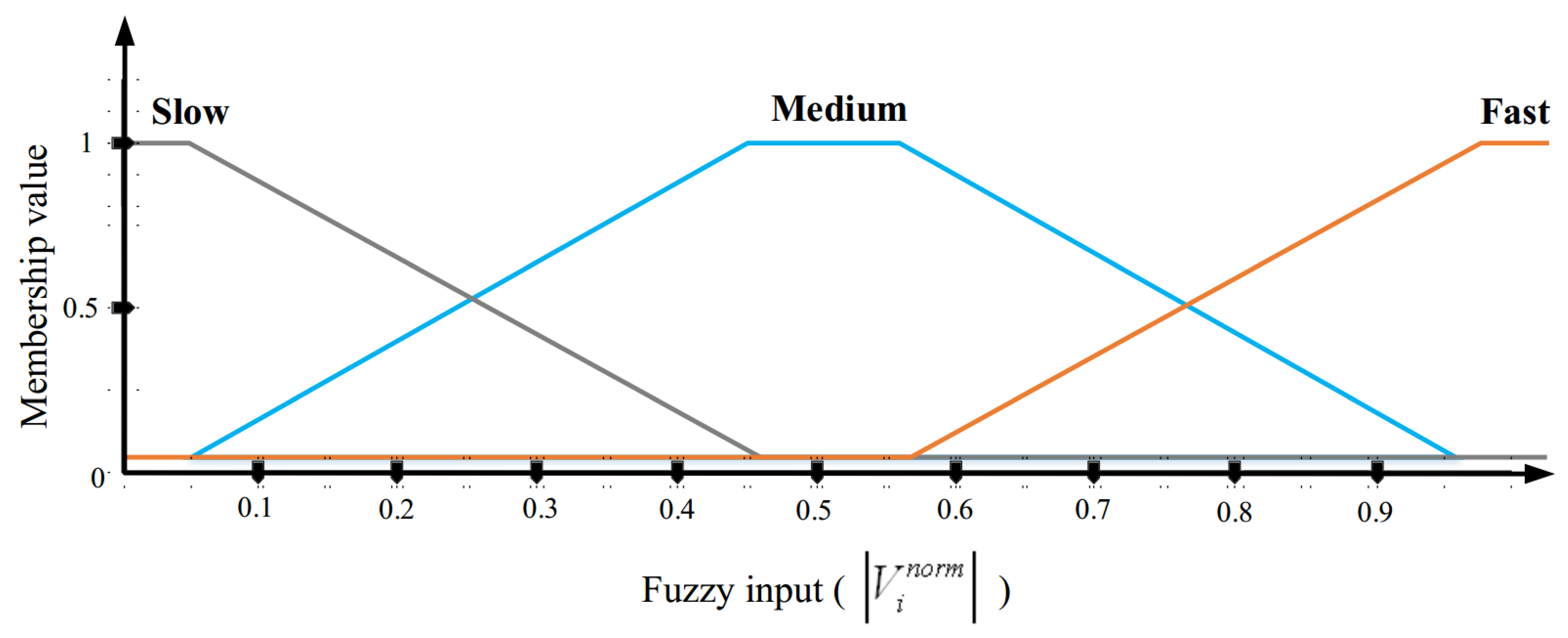
    Now, U A V i must convert V i n o r m into a fuzzy parameter according to the membership diagram presented in Figure 4. According to Figure 4, this fuzzy parameter contains three modes, i.e., slow, medium, and fast.
  • Position prediction error ( e i ): The propagation interval of hello messages and e i have an opposite relationship with each other, so if U A V i estimates its future position with a large error, it should shorten its hello propagation interval to reduce the position prediction error. Note that U A V i has access to its real position through the positioning device. Additionally, it uses the movement equation to estimate its new position. In OLSR+GPSR, each U A V i assumes that its velocity vector v i , x , v i , y , v i , z is fixed in the time period between two consecutive hello messages. As a result, U A V i can calculate its future position in the next hello message based on its previous position x i p r e v i o u s , y i p r e v i o u s , z i p r e v i o u s and its current velocity vector v i , x , v i , y , v i , z .
    x ˜ i n e x t = v i , x H T i + x i p r e v i o u s
    y ˜ i n e x t = v i , y H T i + y i p r e v i o u s
    z ˜ i n e x t = v i , z H T i + z i p r e v i o u s
    where x ˜ i n e x t , y ˜ i n e x t , z ˜ i n e x t is the estimated spatial coordinates of U A V i when receiving the next hello message, and H T i expresses the hello propagation interval.
    Now, the error value ( e i ) between the actual position, i.e., x i n e x t , y i n e x t , z i n e x t , and the estimated position, i.e., x ˜ i n e x t , y ˜ i n e x t , z ˜ i n e x t , is obtained from Equation (6).
    e i = x i n e x t x ˜ i n e x t 2 + y i n e x t y ˜ i n e x t 2 + z i n e x t z ˜ i n e x t 2
    Finally, e i is normalized according to Equation (7) to limit this value to 0 , 1 .
    e i n o r m = e i e max
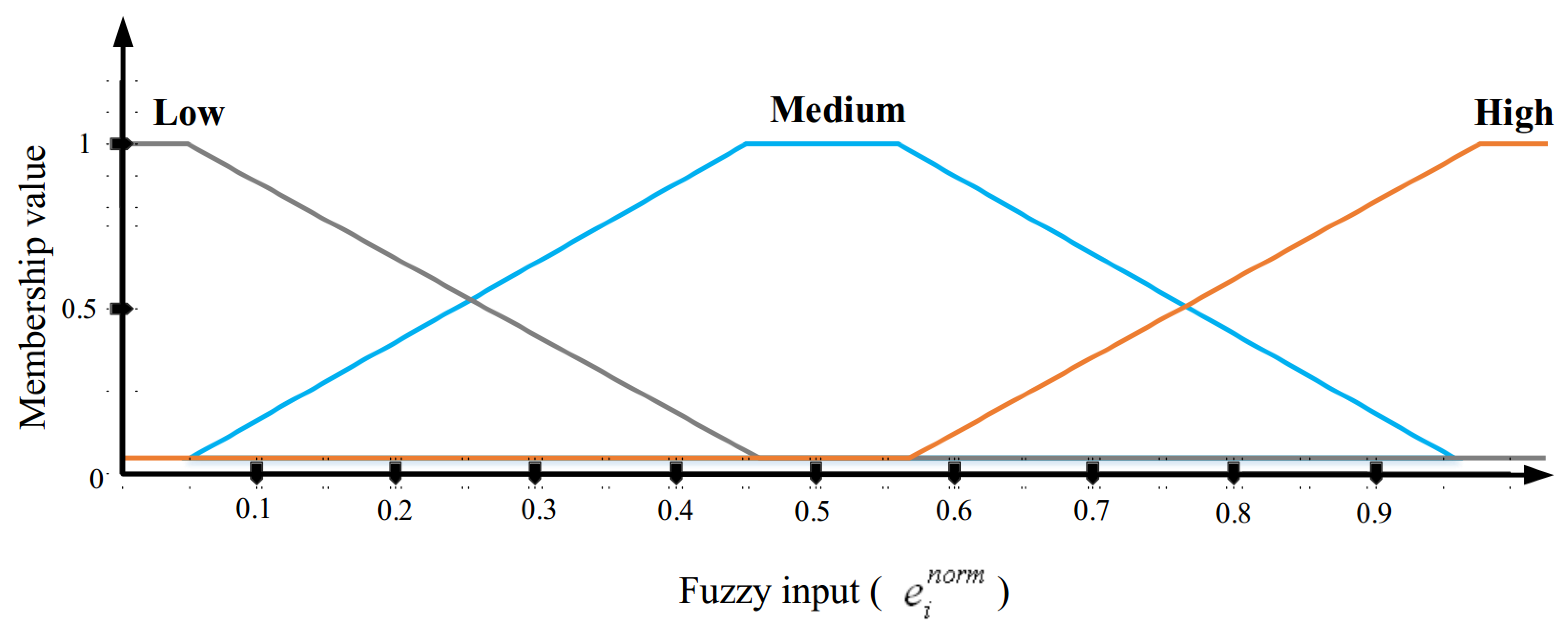
    where e max is the maximum error of the estimated position in the network, and e i n o r m represents the normalized value of e i . Now, U A V i must convert e i n o r m into a fuzzy parameter according to the membership diagram presented in Figure 5. According to Figure 5, this fuzzy parameter involves three states, i.e., low, medium, and high.

5.1.2. Fuzzy Output

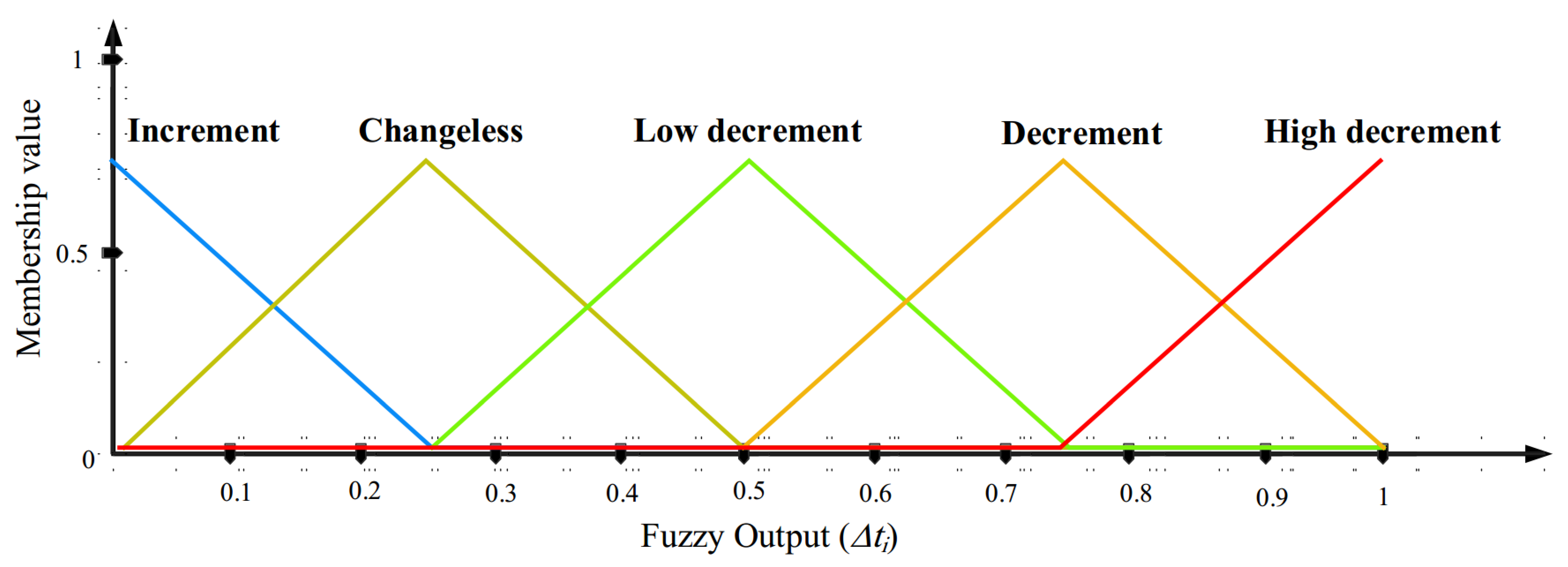
The output of this fuzzy system is the change rate ( Δ t i ) of the hello propagation interval for each U A V i . After determining this change rate, the hello propagation interval ( H T i ) will be equal to H T i + Δ t i . If the change rate Δ t i experiences negative growth, H T i will be shorter, and hello messages will be sent faster. In contrast, if this change rate Δ t i grows positively, H T i will be longer, and hello messages will be sent to neighbors at longer intervals. Δ t i is converted to a crisp value using a defuzzification process called averaging. The membership diagram of this fuzzy parameter is presented in Figure 6. According to this figure, the change rate of the hello propagation interval includes five states, i.e., increment, changeless, low decrement, decrement, and high decrement.

5.1.3. Rule Base

Here, fuzzy rules (IF-THEN rules) are introduced in the proposed fuzzy system. This rule base contains nine fuzzy rules as shown in Table 2. To clarify the concept of each rule, the first rule is defined as follows.
Rule 1: IF the velocity of U A V i is slow AND the position prediction error is low, THEN the change rate of the hello propagation interval will be increment.
Algorithm 1 describes the pseudo code related to this phase. Note that the time complexity of this algorithm is equal to O ( N i ) so that N i indicates the number of adjacent drones of U A V i .
Algorithm 1 Hello message broadcast
Input:  U A V i : i = 1 , 2 , , n
   H T i = 1 s : Default period of time for propagating hello messages in U A V i .
   S T : Simulation time
   N i : The number of adjacent drones of U A V i .
Output:  H T i : The period of time for propagating hello messages in U A V i .
  Begin
 1: repeat
 2:  if  S T mod H T i = 0  then
 3:    UAV i : Connect to a positioning system such as GPS;
 4:    UAV i : Get the next position x i n e x t , y i n e x t , z i n e x t and its velocity v i , x , v i , y , v i , z from GPS;
 5:    UAV i : Record its position, velocity, energy, and occupied buffer capacity in the hello message;
 6:    UAV i : Propagate this hello message for adjacent UAVs;
 7:    UAV i : Obtain the size of its velocity, i.e., V i according to Equation (1);
 8:    UAV i : Get the normalized V i (i.e., V i n o r m ) based on Equation (2);
 9:    UAV i : Transform V i n o r m into a fuzzy variable in accordance with the membership graph in Figure 4;
10:    UAV i : Approximate the next position x ˜ i n e x t , y ˜ i n e x t , z ˜ i n e x t based on Equations (3)–(5);
11:    UAV i : Compute the error value ( e i ) between x i n e x t , y i n e x t , z i n e x t and x ˜ i n e x t , y ˜ i n e x t , z ˜ i n e x t based on Equation (6);
12:    UAV i : Obtain the normalized error value ( e i n o r m ) in accordance with Equation (7);
13:    UAV i : Transform e i n o r m into a fuzzy variable in accordance with the membership graph in Figure 5;
14:    UAV i : Get the broadcast period change rate ( Δ t i ) based on Figure 6 and the rule base in Table 1;
15:    UAV i : Obtain H T i = H T i + Δ t i ;
16:  end if
17:  for  j = 1 to N i  do
18:   if  U A V i gets a new hello message from U A V j  then
19:     UAV i : Record the information of U A V j in its neighbor table;
20:   end if
21:  end for
22:   S T = S T 1 ;
23: until  S T = 0
   End

5.2. Selecting MPR Nodes

In OLSR+GPSR, the MPR selection algorithm is used to obtain the information of MPRs associated with each U A V i . The task of MPRs in OLSR+GPSR is different from their task in OLSR. In OLSR, these nodes broadcast TC messages throughout the network so that network topology information is globally available to all UAVs to calculate routing paths and update their routing table. This work is extremely costly in terms of communication overhead and energy consumption and increases delay in the routing process. Furthermore, this information is often invalid quickly due to the highly mobility of UAVs in FANET, and the routes formed between UAVs are often broken even without use in the data transmission process and must be updated again. According to the mentioned points, OLSR+GPSR seeks to reduce the tasks of MPRs to lower energy consumption and improve network lifetime. In this regard, MPRs do not need to propagate TC messages throughout the network and UAVs do not need to calculate all routes in the network. In OLSR+GPSR, MPRs are responsible for sending data packets to the destination in a greedy manner. They use the routing technique provided in GPSR to reduce routing overhead and delay. In this regard, each U A V i must specify its own MPR set, i.e., S i M P R = U A V 1 , i M P R , U A V 2 , i M P R , , U A V r , i M P R , , U A V M M P R so that U A V i has at least one communication path to its two-hop neighbors through its MPRs. Note that the number of U A V r , i M P R in S i M P R is equal to M. To achieve this MPR set, U A V i must first make two sets, namely a one-hop neighbor set N i 1 h o p = n 1 , i 1 h o p , n 2 , i 1 h o p , , n p , i 1 h o p , , n P , i 1 h o p and a two-hop neighbor set N i 2 h o p = n 1 , i 2 h o p , n 2 , i 2 h o p , , n q , i 2 h o p , , n Q , i 2 h o p . This process includes two steps:
  • Calculating the score of one-hop neighboring nodes;
  • MPR selection algorithm.

5.2.1. Calculating the Score of One-Hop Neighboring Nodes

In OLSR, each U A V i determines its MPRs ( U A V r , i M P R , so that r = 1 , 2 , , M ) only based on the neighbor degree, whereas it is not enough because MPRs such as U A V r , i M P R may go out of the communication range of U A V i in a very short time due to the high mobility of UAVs in FANET. As a result, communication links are quickly cut and the information about the entire network topology must be updated. This is associated with a lot of communication overhead, high energy consumption, and a lot of delay. For this reason, this problem has been solved in OLSR+GPSR. Hence, in addition to the neighbor degree, each U A V i should pay attention to node stability, occupied buffer capacity, and residual energy to choose each U A V r , i M P R . To achieve this goal, U A V i calculates a score S p for each one-hop neighbor n p , i 1 h o p (where p = 1 , 2 , , P ) based on these four components.
  • Neighbor degree ( ND p ): In OLSR+GPSR, similar to OLSR, U A V i pays attention to the neighbor degree of n p , i 1 h o p (i.e., N D p ), which is equal to the number of its one-hop neighbor to determine S i M P R = U A V 1 , i M P R , U A V 2 , i M P R , , U A V r , i M P R , , U A V R M P R . N D p is obtained from its neighbor table. This component represents the number two-hop neighboring UAVs of U A V i that n p , i 1 h o p covers in the network. Thus, U A V i can choose suitable one-hop neighbors such as n p , i 1 h o p as U A V r , i M P R because n p , i 1 h o p with high N D p has more communication links with other nodes and creates stable paths in the network. This decreases routing overhead. N D p and S p are directly related to each other. Therefore, U A V i increases the score of n p , i 1 h o p , which has a higher N D p so that n p , i 1 h o p gets a higher priority to be selected as U A V r , i M P R . U A V i uses Equation (8) to perform a normalization operation on N D p corresponding to n p , i 1 h o p (where p = 1 , 2 , , P ) so that this element is limited to 0 , 1 .
    N D p n o r m = N D p N D max
    Here, N D p n o r m is the normalized value of N D p , and N D max is equal to the maximum degree of the one-hop neighbors in N i 1 h o p = n 1 , i 1 h o p , n 2 , i 1 h o p , , n p , i 1 h o p , , n P , i 1 h o p (i.e., N D max = max n p , i 1 h o p N i 1 h o p A N D p = 1 , 2 , , P N D p ).
  • Node stability ( NS p ): In OLSR+GPSR, U A V i measures the stability of n p , i 1 h o p (i.e., N S p ) based on the effective distance, relative velocity, and movement direction of n p , i 1 h o p to determine the most stable U A V r , i M P R in S i M P R . N S p is calculated according to Equation (9).
    N S p = 1 E D i p + 2 1 V i p n o r m + 3 1 θ i p n o r m
    Here, i = 1 3 i = 1 and 1 , 2 , and 3 are the weight coefficients to determine the effect of each component (i.e., effective distance, relative velocity, and movement direction) on N S p . In OLSR+GPSR, the effect of all three parameters, including effective distance ( E D i p ), relative velocity ( V i p ), and movement direction ( θ i p ), on N S p is the same (i.e., 1 = 2 = 3 ). These three parameters are explained below.
    Effective distance ( ED ip ): The distance between U A V i and n p , i 1 h o p has an important effect on node stability. If this distance is close to the effective area of U A V i , n p , i 1 h o p is a stable neighbor. Otherwise, it is not suitable to choose this node as the MPR. In Figure 7, the white area shows the effective area of U A V i .
    In general, the stability of n p , i 1 h o p and its effective distance have a direct relationship with each other. Hence, if the distance between U A V i and n p , i 1 h o p is very short (i.e., d i p < R min ), the selection of n p , i 1 h o p as U A V r , i M P R is not a useful option because U A V r , i M P R plays the role of the next-hop node in the routing process, and its proximity to U A V i will cause an excessive increase in the number of hops in the route. In Figure 7, the distance between U A V i and U A V 1 is less than R min . Thus, U A V 1 should not be selected as an MPR node. On the other hand, if the distance between U A V i and n p , i 1 h o p is very long (i.e., d i p > R max ), the selection of n p , i 1 h o p as U A V r , i M P R is not appropriate because it may go out of the communication range of U A V i very quickly. In Figure 7, the distance between U A V i and U A V 3 is more than R max . Thus, U A V 3 should not be selected as an MPR node, whereas if the distance between U A V i and n p , i 1 h o p is in the effective range (i.e., R min d i p R max ), the selection of n p , i 1 h o p as U A V r , i M P R is a very good option. In Figure 7, the distance between U A V i and U A V 2 is between R min and R max . Thus, U A V 2 is a stable neighbor and can be selected as an MPR node. This issue is stated in Equation (10).
    E D i p = d i p R min , d i p < R min 1 , R min d i p R max d i p R max R R max , R max < d i p R
    where R is the communication radius of UAVs, and d i p is the Euclidean distance between n p , i 1 h o p and U A V i obtained from Equation (11).
    d i p = x i c u r r e n t x p c u r r e n t 2 + y i c u r r e n t y p c u r r e n t 2 + z i c u r r e n t z p c u r r e n t 2
    Relative velocity ( V ip ): The relative velocity of n p , i 1 h o p with regard to U A V i is an important factor in determining node stability. This factor determines whether these two UAVs (i.e., U A V i and n p , i 1 h o p ) fly at a relatively similar velocity. If this factor approaches zero, then the velocities of U A V i and n p , i 1 h o p are similar. Therefore, they do not leave the neighboring area of each other quickly. In this case, n p , i 1 h o p is a stable one-hop neighbor, which can create stable paths and decrease the number of path failures. Now, if the relative velocity is large, n p , i 1 h o p has weak stability. The length of the relative velocity of n p , i 1 h o p with regard to U A V i (i.e., V i p ) is calculated according to Equation (12).
    V i p = v i , x v p , x 2 + v i , y v p , y 2 + v i , z v p , z 2
    where v i , x , v i , y , v i , z and v p , x , v p , y , v p , z are the velocity vectors of U A V i and n p , i 1 h o p , respectively.
    V i p is normalized through Equation (13).
    V i p n o r m = V i p V max
    Here, V i p n o r m is the normalized value of V i p . V max is the maximum relative velocity of one-hop neighbors in N i 1 h o p = n 1 , i 1 h o p , n 2 , i 1 h o p , , n p , i 1 h o p , , n P , i 1 h o p , i.e., V max = max n p , i 1 h o p N i 1 h o p A N D p = 1 , 2 , , P V i p .
    Movement direction ( θ ip ): The direction of n p , i 1 h o p relative to U A V i (i.e., θ i p ) is an effective factor to evaluate the stability of n p , i 1 h o p . If n p , i 1 h o p moves in the opposite direction to U A V i , n p , i 1 h o p is known as an unstable node, and vice versa. θ i p is calculated based on Equation (14).
    θ i p = cos 1 v i , x v p , x + v i , y v p , y + v i , z v p , z v i , x 2 + v i , y 2 + v i , z 2 × v p , x 2 + v p , y 2 + v p , z 2 , 0 θ i p π
    where v i , x , v i , y , v i , z and v p , x , v p , y , v p , z are the velocity vectors of U A V i and n p , i 1 h o p , respectively.
    Now, θ i p is normalized based on Equation (15).
    θ i p n o r m = θ i p π
    So θ i p n o r m is the normalized value of θ i p in 0 , 1 .
  • Occupied buffer capacity ( NB p ): In OLSR+GPSR, the occupied buffer capacity of n p , i 1 h o p (i.e., N B p ) is used to determine U A V r , i M P R in S i M P R . N B p is calculated based on the ratio of the number of data packets in the buffer queue to the size of the buffer. This parameter is exchanged through hello messages. There is an inverse relationship between N B p and S p because if N B p is a large value, it shows the presence of congestion and high traffic in n p , i 1 h o p . This congestion decreases energy efficiency and network lifetime. As a result, U A V i gives a lower score to n p , i 1 h o p with a higher N B p so that n p , i 1 h o p has a lower priority to be selected as U A V r , i M P R . U A V i uses Equation (16) to perform a normalization operation on N B p corresponding to n p , i 1 h o p ( p = 1 , 2 , , P ) to limit this element to 0 , 1 .
    N B p n o r m = N B p N B max
    Here, N B p n o r m is the normalized value of N B p , and N B max is equal to the maximum occupied buffer capacity of one-hop neighbors in N i 1 h o p (i.e., N B max = max n p , i 1 h o p N i 1 h o p A N D p = 1 , 2 , , P N B p ).
  • Residual energy ( NE p ): In OLSR+GPSR, U A V i applies the remaining energy of n p , i 1 h o p (i.e., N E p ) to determine U A V r , i M P R in S i M P R . When deciding on MPRs, this component is really vital for calculating the score of n p , i 1 h o p because each MPR node such as U A V r , i M P R experiences higher routing overhead than other nodes. Hence, its energy consumption is high. N E p is obtained from the neighbor table, and there is a direct relationship between N E p and S p . If N E p is high, n p , i 1 h o p is more stable and has priority to be selected as U A V r , i M P R . U A V i normalizes N E p corresponding to n p , i 1 h o p ( p = 1 , 2 , , P ) through Equation (17) so that this parameter is limited to 0 , 1 .  
    N E p n o r m = N E p N E max
    Here, N E p n o r m is the normalized value of N E p , and N E max is equal to the maximum remaining energy in N i 1 h o p = n 1 , i 1 h o p , n 2 , i 1 h o p , , n p , i 1 h o p , , n P , i 1 h o p (i.e., N E max = max n p , i 1 h o p N i 1 h o p A N D p = 1 , 2 , , P N E p ).
Therefore, the score of each n p , i 1 h o p ( S p ) is obtained from Equation (18).
S p = λ 1 N D p n o r m + λ 2 N S p n o r m + λ 3 1 N B p n o r m + λ 4 N E p n o r m
Here, λ 1 , λ 2 , λ 3 , and λ 4 are the weight coefficients to express the effect of each parameter (i.e., neighbor degree, node stability, occupied buffer capacity, and remaining energy) on S p and i = 1 4 λ i = 1 . In OLSR+GPSR, the effect of all four parameters is considered to be the same (i.e., λ 1 = λ 2 = λ 3 = λ 4 ).

5.2.2. MPR Selection Algorithm

In OLSR+GPSR, the MPR selection algorithm includes the following steps:
1.  U A V i makes three sets, S i M P R =   , N i 1 h o p = n 1 , i 1 h o p , n 2 , i 1 h o p , , n p , i 1 h o p , , n P , i 1 h o p , and N i 2 h o p = n 1 , i 2 h o p , n 2 , i 2 h o p , , n q , i 2 h o p , , n Q , i 2 h o p .
2.  U A V i calculates S p for each n p , i 1 h o p in N i 1 h o p according to Section 5.2.1.
3. If U A V i finds a n p , i 1 h o p with W i l l i n g n e s s = W I L L A L W A Y S , it inserts n p , i 1 h o p into S i M P R . Willingness is an index recorded in hello messages to determine the willingness of UAVs to transmit traffic, and its value is limited to 1 , 7 . Nodes with W i l l i n g n e s s = W I L L N E V E R are never selected as an MPR, whereas nodes with W i l l i n g n e s s = W I L L A L W A Y S always become an MPR.
4. If U A V i and n q , i 2 h o p have only one communication path through n p , i 1 h o p , U A V i should select n p , i 1 h o p as a U A V r , i M P R .
5.  U A V i is responsible for removing all one-hop neighboring nodes n p , i 1 h o p determined as U A V r , i M P R from N i 1 h o p .
6.  U A V i is responsible for removing all two-hop neighbors n q , i 2 h o p , which have at least one communication path to U A V i through MPRs, from N i 2 h o p .
7. This step is repeated until N i 2 h o p is empty (i.e., N i 2 h o p =   ):
  • U A V i sorts the members of N i 1 h o p (i.e., n p , i 1 h o p so that p = 1 , 2 , , P ) based on S p .
  • If some of n p , i 1 h o p have the same score, those with a higher neighbor degree have a higher priority.
  • U A V i chooses a n p , i 1 h o p with the highest score (the first member of N i 1 h o p , i.e., n 1 , i 1 h o p ) and inserts it as U A V r , i M P R into S i M P R .
  • U A V i removes n 1 , i 1 h o p determined as U A V r , i M P R from N i 1 h o p .
  • All IDs of two-hop neighbors (such as n q , i 2 h o p ) that have at least one communication path to U A V i through MPRs in S i M P R are removed from N i 2 h o p .
The pseudo-code related to this phase is described in Algorithm 2. The time complexity of this algorithm is O ( Q P log P ) so that P and Q indicate the sizes of two sets N i 1 h o p and N i 2 h o p , respectively.
Algorithm 2  The selection process of multi-point relays (MPRs)
Input:  U A V i : i = 1 , 2 , , n
   H T i = 1 s : Default period of time for propagating hello messages in U A V i .
   U A V r , i M P R : r = 1 , 2 , , M
   n p , i 1 h o p : A one-hop neighbor of U A V i .
   S p : The score of n p , i 1 h o p .
   N i 1 h o p = n 1 , i 1 h o p , n 2 , i 1 h o p , , n p , i 1 h o p , , n P , i 1 h o p
   N i 2 h o p = n 1 , i 2 h o p , n 2 , i 2 h o p , , n q , i 2 h o p , , n Q , i 2 h o p
 Output:  S i M P R = U A V 1 , i M P R , U A V 2 , i M P R , , U A V r , i M P R , , U A V M M P R
  Begin
 1: for  p = 1 to P do
 2:   UAV i : Obtain N D p corresponding to n p , i 1 h o p from its neighbor table;
 3:   UAV i : Normalized N D p according to Equation (8);
 4:   UAV i : Gain N S p corresponding to n p , i 1 h o p based on Equation (9);
 5:   UAV i : Extract N B p corresponding to n p , i 1 h o p from its neighbor table;
 6:   UAV i : Calculate the normalized N B p (i.e., N B p n o r m ) based on Equation (16);
 7:   UAV i : Obtain N E p corresponding to n p , i 1 h o p from its neighbor table;
 8:   UAV i : Get the normalized N E p (i.e., N E p n o r m ) in accordance with Equation (17);
 9:   UAV i : Compute the score ( S p ) related to n p , i 1 h o p according to Equation (18);
10: end for
11:  UAV i : Consider an empty set S i M P R =   to record the selected MPRs;
12: for  q = 1 to Q do
13:  for  p = 1 to P do
14:   if  n p , i 1 h o p in N i 1 h o p has W i l l i n g n e s s = W I L L A L W A Y S  then
15:     UAV i : Determine this n p , i 1 h o p as a member of S i M P R ;
16:     UAV i : Delete this n p , i 1 h o p from N i 1 h o p ;
17:     UAV i : Remove the 2-hop neighbors ( n q , i 2 h o p ) covered by n p , i 1 h o p from N i 2 h o p ;
18:    else if there is a n q , i 2 h o p in N i 2 h o p covered only by n p , i 1 h o p then
19:     UAV i : Determine this n p , i 1 h o p as a member of S i M P R ;
20:     UAV i : Eliminate this n p , i 1 h o p from N i 1 h o p ;
21:     UAV i : Delete the 2-hop neighbors ( n q , i 2 h o p ) covered by n p , i 1 h o p from N i 2 h o p ;
22:   end if
23:  end for
24: end for
25: while  N i 2 h o p =    do
26:   UAV i : Sort the members of N i 1 h o p based on their S p ;
27:  if two one-hop neighbor have the same S p  then
28:    UAV i : Prioritize these one-hop neighbors based on their N D p ;
29:  end if
30:   UAV i : Select n p , i 1 h o p the first member of N i 1 h o p as U A V r , i M P R ;
31:   UAV i : Eliminate this n p , i 1 h o p from N i 1 h o p ;
32:   UAV i : Delete the 2-hop neighbors ( n q , i 2 h o p ) covered by n p , i 1 h o p from N i 2 h o p ;
33: end while
   End

5.3. Greedy and Perimeter Forwarding Techniques

In OLSR+GPSR, the routing process follows the GPSR protocol, except that the next-hop nodes are only selected from S i M P R = U A V 1 , i M P R , U A V 2 , i M P R , , U A V r , i M P R , , U A V R M P R . In this process, U A V i uses the greedy technique to choose the U A V r , i M P R closest to the destination. Now, if U A V i cannot find U A V r , i M P R in S i M P R that is closer to the destination than itself, then U A V i faces the local optimum problem and leaves the greedy forwarding technique. In this case, it enters the path recovery phase and decides on the next hop node based on the right-hand rule (perimeter forwarding mode). The path recovery phase in OLSR+GPSR is completely similar to that in GPSR. See the pseudo code of this process in Algorithm 3. In the worst case, the time complexity of this algorithm is O ( n M ) so that n and M are the total number of UAVs and the number of MPRs related to U A V i , respectively.
Algorithm 3 Routing process
Input:  U A V i : i = 1 , 2 , , n
   S i M P R = U A V 1 , i M P R , U A V 2 , i M P R , , U A V r , i M P R , , U A V M M P R
Output: Routing path between source and destination.
  Begin
 1: repeat
 2:  if  U A V i find the nearest U A V r , i M P R to the destination then
 3:    UAV i : Choose this U A V r , i M P R as the next-hop node;
 4:    UAV i : Forward the data packet to this U A V r , i M P R using the greedy forwarding mode in GPSR;
 5:  else if there is no U A V r , i M P R close to the destination compared the current node then
 6:    UAV i : Select the next-hop node using the perimeter forwarding mode in GPSR;
 7:    UAV i : Forward the data packet to the next-hop node;
 8:  end if
 9: until the data packet reaches the destination
   End

6. Simulation and Evaluation of Results

In this section, OLSR+GPSR is run on the network simulator version 3 (NS3) [33,34,35]. Then, a comparison is made between its performance and the three routing methods, namely Gangopadhyay et al. [16], P-OLSR [17], and improved OLSR-ETX [18]. The simulation process considers two modes to evaluate the performance of different schemes: (1) the change in network density and (2) the change in the velocity of UAVs. To perform this operation, it is assumed that the network environment includes a three-dimensional space with the size of 3000 × 3000 × 3000 m3. In the network environment, 10 to 50 UAVs are randomly deployed, and their velocity varies between 10 and 50 m/s. The transmission radius of these UAVs is 500 m, and their initial energy is 100 Joules. Furthermore, the movement model of UAVs follows the three-dimensional Gauss Markov model (3D GM) [36,37]. In the simulation operation, the traffic model has a constant bit rate (CBR), and the size of data packets is 512 bytes. In addition, the MAC layer protocol supports IEEE 802.11b standard. The execution time of this simulation process is 500 s. For increasing the accuracy of the simulation results, the simulation process is repeated 10 times. The simulation parameters are stated in Table 3 in summary. The evaluation process examines four criteria, namely end-to-end delay, packet delivery rate, routing overhead, and throughput.

6.1. End-to-End Delay (EED)

Delay is an evaluation metric obtained through Equation (19). This means the time period from when a data packet is sent from the source UAV until it arrives at the destination UAV.
E E D = P K i P = P K 1 , , P K n T R P K i T S P K i r = 1 n r P K r
where P K r and n r are the packets delivered to the destination UAV and their number, respectively. P K i means the i-th packet from the set of all packets (P). In addition, T R P K i and T S P K i represent the reception moment and the sending moment, respectively.
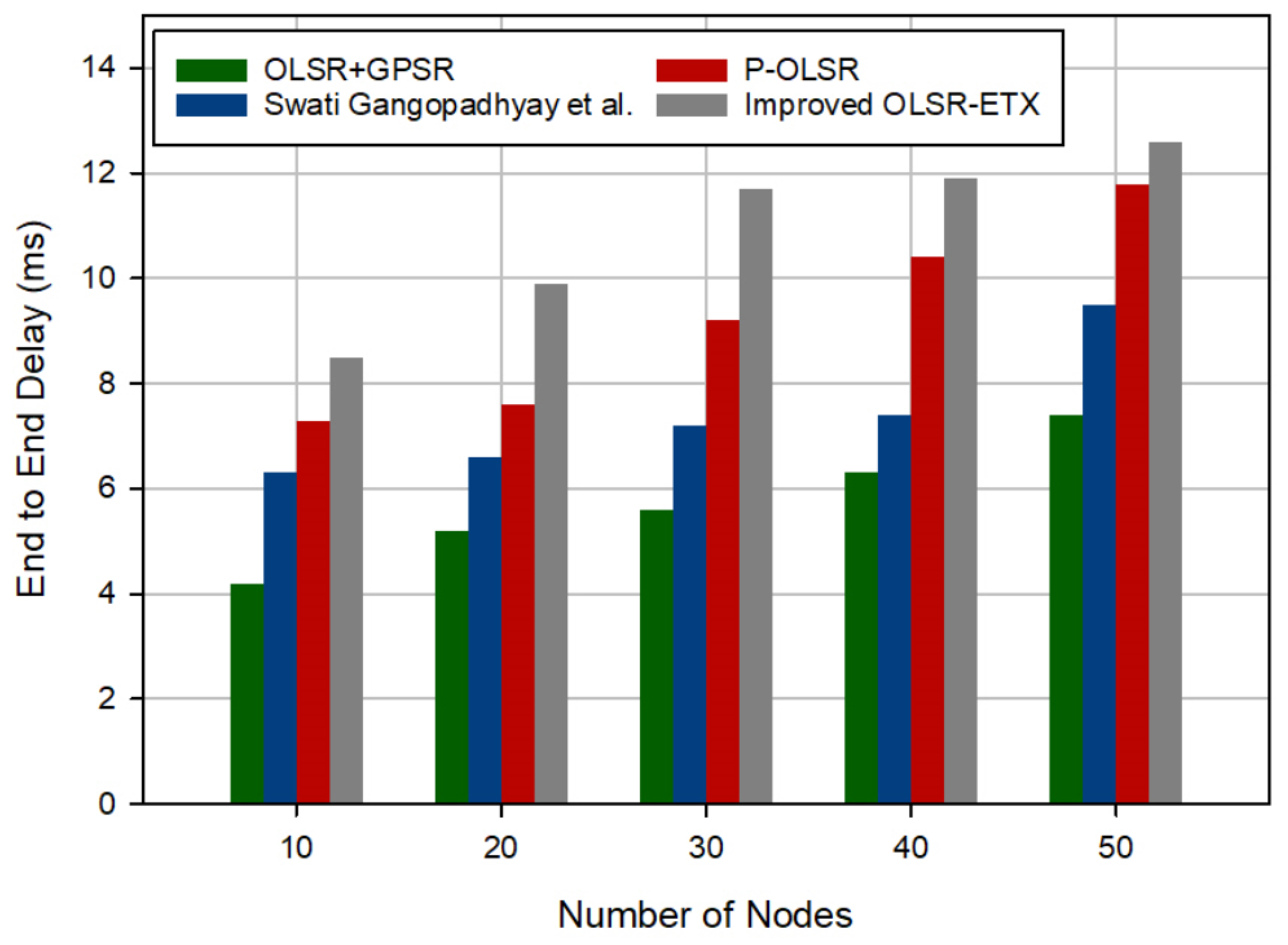
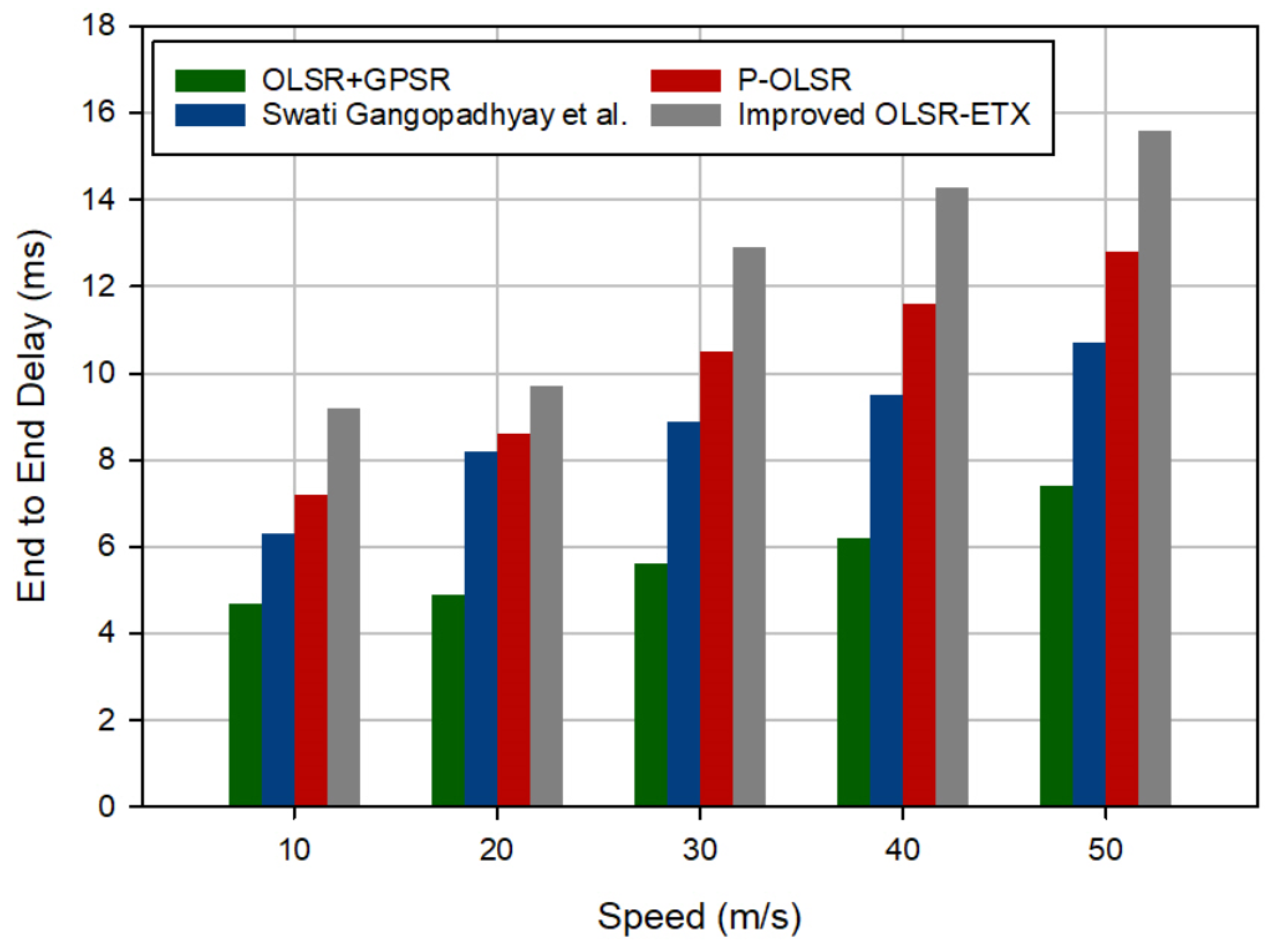
Figure 8 compares the end-to-end delay in different schemes so that the number of UAVs is between 10 and 50, and their speed is set to 20 m/s. As shown in this figure, OLSR+GPSR has reduced EED by 22.43%, 38.01%, and 47.44% compared to Gangopadhyay et al., P-OLSR, and enhanced OLSR-ETX. Its main reason is that OLSR+GPSR has removed two steps, namely broadcasting TC messages and calculating transmission routes between all UAVs, and instead, it uses a greedy forwarding technique, whereas Gangopadhyay et al., P-OLSR, and improved OLSR-ETX use the TC message broadcast process to find all possible routes between UAVs but it is very time-consuming. Another reason for this issue is that OLSR+GPSR determines MPRs based on several parameters, including the neighbor degree, node stability (which is obtained from the position and movement information of UAVs), occupied buffer capacity, and remaining energy. This issue leads to the selection of stable MPRs, which reduces the need to update these nodes and, consequently, lowers the delay in FANET. Another point inferred from Figure 8 is that EED and the density of UAVs have a direct relationship with each other, and if the density of nodes is high, EED in the routing process will increase in all schemes. Its reason can be the increase in traffic and congestion in the network. It causes a number of lost data packets, which must be retransmitted. In addition, Figure 9 shows EED in different methods, so that the number of nodes is set to 30, and their velocity is between 10 and 50 m/s. According to this figure, OLSR+GPSR has reduced this evaluation metric by 33.94%, 43.19%, and 53.32% in comparison with Gangopadhyay et al., P-OLSR, and enhanced OLSR-ETX. We have stated the reasons above. Moreover, in Figure 9, it can be seen that EED in the routing process is increasing when the velocity of UAVs is rising because increasing the velocity of UAVs will lead to faster topology changes in the network. As a result, MPRs must be updated in a shorter period of time. This issue will increase EED in the routing process.

6.2. Packet Delivery Rate (PDR)

PDR is an evaluation metric calculated based on Equation (20). It measures the ratio of packets received by the destination UAV to packets sent from the source UAV.
P D R = r = 1 n r P K r s = 1 n s P K s × 100
where P K r and n r are the packets entered to the destination UAV and their number, respectively. Furthermore, P K s and n r represent the packets sent from the source UAV and their number, respectively.
Figure 10 shows PDR in different schemes. It is assumed that the number of UAVs is between 10 and 50, and their velocity is a fixed value (20 m/s). According to this figure, OLSR+GPSR has increased this evaluation metric by 4.13%, 16.86%, and 21.51% in comparison with Gangopadhyay et al., P-OLSR, and improved OLSR-ETX, respectively. This is because the proposed method pays attention to node stability along with neighbor degree when choosing MPRs. The stability scale is calculated based on the position and mobility (i.e., velocity and movement angle) information of UAVs. As a result, MPRs in OLSR+GPSR are more stable than other methods. This reduces the number of lost packets and, consequently, increases PDR. On the other hand, in the proposed method, the buffer information of UAVs is considered in the MPR selection process to prevent congestion in UAVs. This also has a positive effect on increasing PDR. As shown in Figure 10, PDR in OLSR+GPSR does not change based on the number of UAVs, while PDR in other methods is decreasing when the number of UAVs is increasing. This issue is rooted in the fact that the increase in the number of UAVs causes an increase in congestion in FANET. As a result, some packets are lost due to collisions or high traffic in the network, but OLSR+GPSR takes into account the buffer capacity of the flying nodes in the MPR selection process and prevents congestion in the network, and consequently, PDR in our scheme experiences an almost constant rate. Furthermore, Figure 11 makes a comparison between different methods in terms of PDR when the number of UAVs is equal to 30, and their velocity is between 10 and 50 m/s. Based on this figure, OLSR+GPSR has increased PDR by 14%, 23.27%, and 16.11% in comparison with Gangopadhyay et al., P-OLSR, and improved OLSR-ETX. The reasons related to this issue were stated above. On the other hand, different methods experience a lower PDR when increasing the velocity of UAVs. This is caused by higher changes in the network topology. The better performance of the proposed method in comparison with other methods is due to considering the mobility information of UAVs in the routing process. OLSR+GPSR adjusts the propagation period of hello messages according to the velocity of UAVs. This mechanism makes more adaptability between OLSR+GPSR and the dynamic environment of FANET.

6.3. Routing Overhead

Routing overhead is an evaluation metric that is calculated using Equation (21). It means the ratio of number of sent control packets to all data packets. Note that OLSR-based routing methods have two types of control packets: hello packet and TC packet.
R O = h = 1 n H e l l o H e l l o h + t = 1 n T C T C t s = 1 n s P K s
where P K s and n s represent the packets sent from the source UAV and their total number, respectively. H e l l o h and n H e l l o are the h-th hello packet and the total number of hello packets in the routing process, respectively. Furthermore, T C t and n T C indicate the t-th TC packet and the total number of TC packets in the routing process.
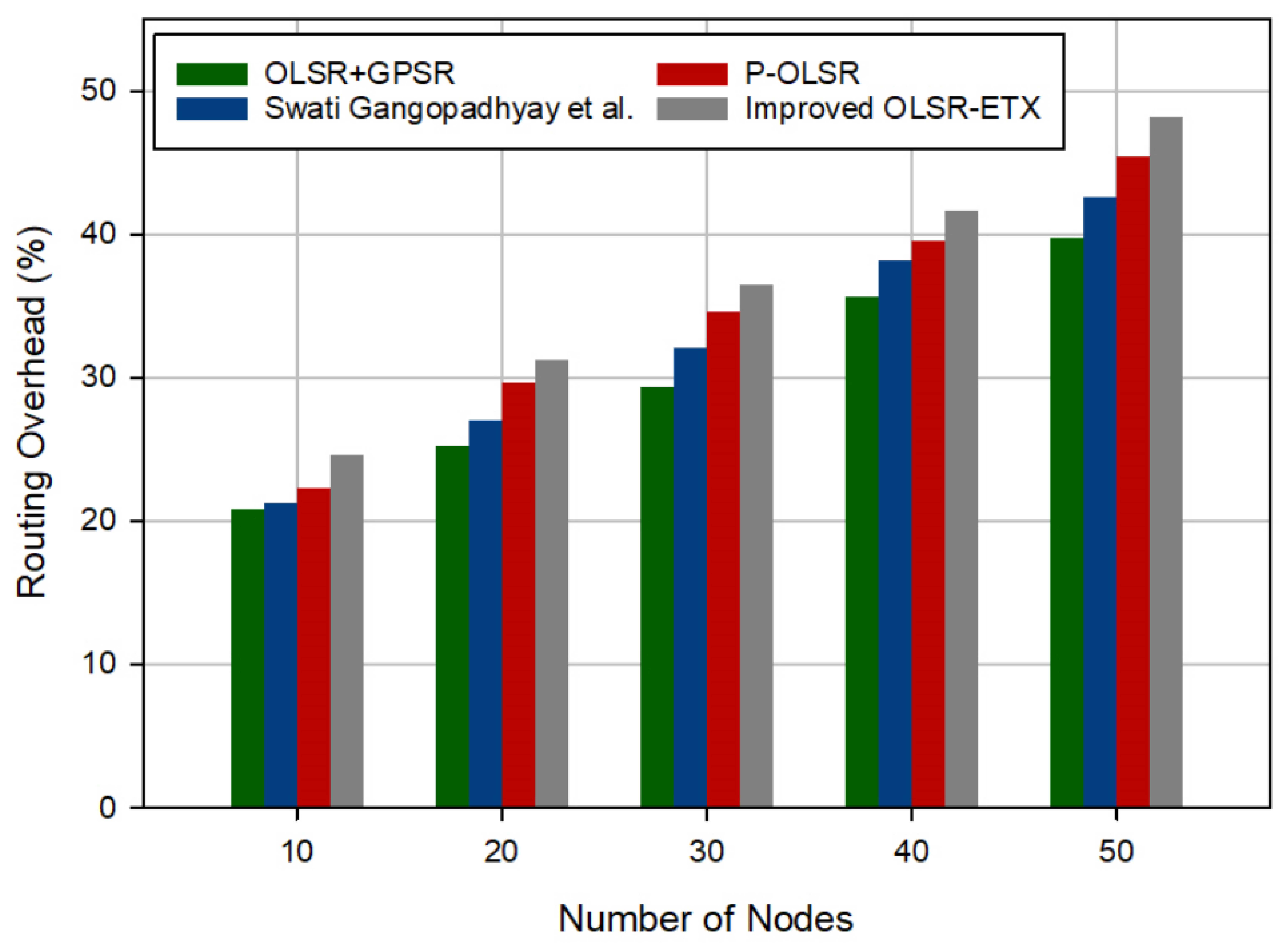
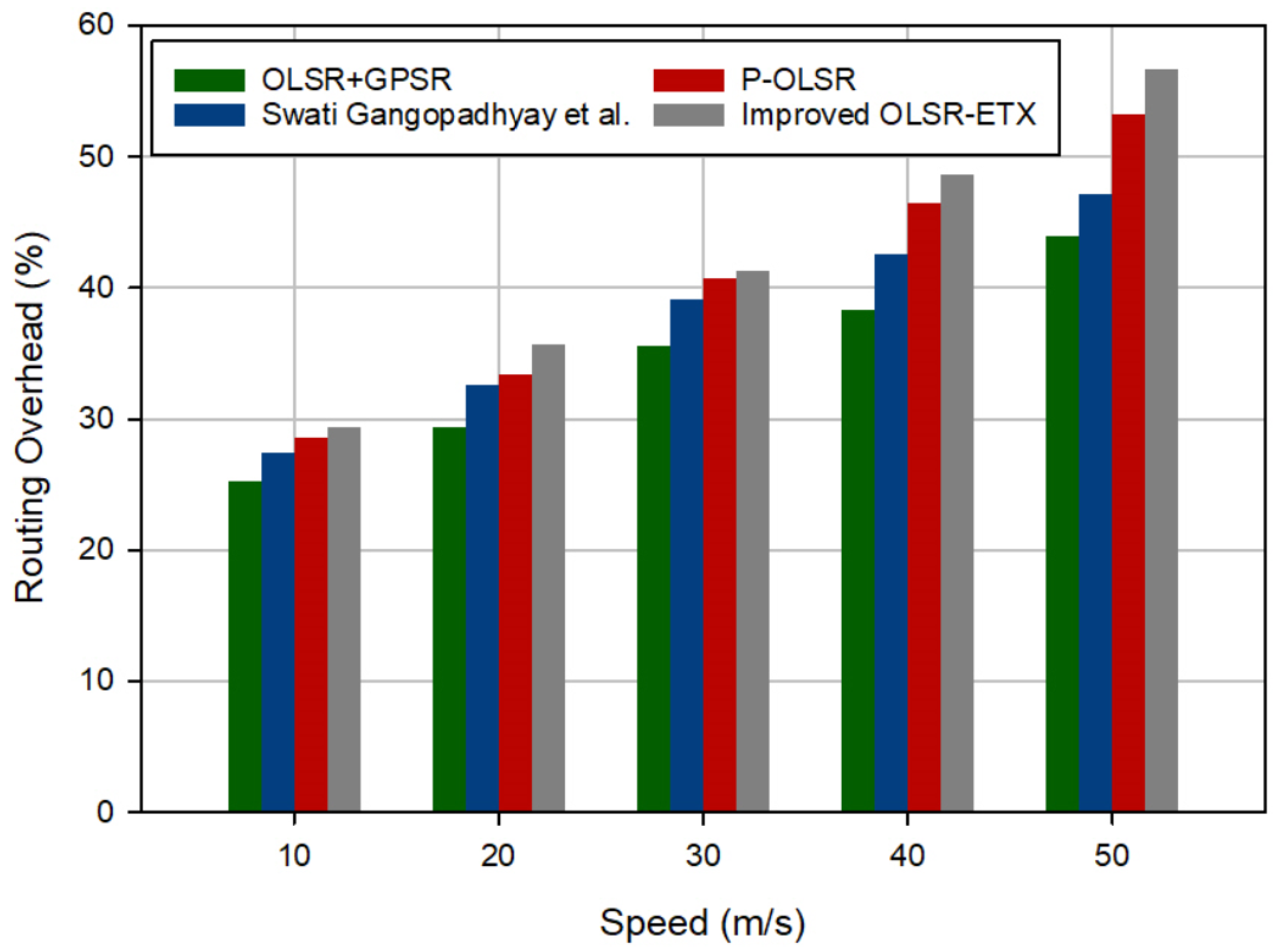
Figure 12 shows the routing overhead in different methods when the number of UAVs is changed between 10 and 50, and their speed is set to 20 m/s. According to this figure, OLSR+GPSR has reduced the routing overhead by approximately 6.33%, 11.95%, and 17.12% in comparison with Gangopadhyay et al., P-OLSR, and improved OLSR-ETX, respectively. The good performance of the proposed method in comparison with other methods has two reasons. First, OLSR+GPSR uses a fuzzy system to dynamically adjust the hello message propagation interval based on velocity and position prediction error so that high-speed UAVs have a shorter hello propagation period and low-speed UAVs experience a longer hello propagation period. As a result, the proposed method is more compatible with the dynamic environment of FANET than other routing methods. In addition, OLSR+GPSR eliminates the two phases, namely broadcasting TC messages and calculating transmission routes, and applies greedy and perimeter forwarding techniques. Hence, OLSR+GPSR reduces routing overhead significantly. In addition, according to Figure 12, it can be seen that there is a direct relationship between the routing overhead and the number of UAVs. Therefore, when the number of UAVs is increasing, the routing overhead is also increasing. This is because when the number of UAVs is high, more control messages will be exchanged between them in the network, meaning that, the routing overhead is high. Figure 13 shows a comparison between routing overhead in different methods. In this experiment, it is assumed that the number of UAVs is 30, and their velocity is between 10 and 50 m/s. This figure shows that OLSR+GPSR has reduced the routing overhead by 8.68%, 14.77%, and 18.52% in comparison with Gangopadhyay et al., P-OLSR, and improved OLSR-ETX, respectively. We have mentioned the reasons above. Additionally, this figure confirms the existence of a direct relationship between the routing overhead and the velocity of UAVs because the higher velocity of UAVs will increase the instability of UAVs, which causes higher topology changes in the network. This issue increases the number of control packets due to the need for faster updating MPRs.

6.4. Throughput

Throughput is an evaluation metric obtained through Equation (22). It means the ratio of all packets entered at the destination UAV to the time needed to transfer them.
T h r o u g h p u t = r = 1 n r P K r T r e q u i r e d
where P K r and n r indicate the packets entered to the destination UAV and their total number, respectively. Furthermore, T r e q u i r e d is the time needed to send these packets.
Figure 14 shows a comparison between the throughput of different methods when the number of UAVs is between 10 and 50, and their velocity is set to 20 m/s. According to this figure, OLSR+GPSR increases throughput by 27.78%, 30.01%, and 32.33% in comparison with Gangopadhyay et al., P-OLSR, and improved OLSR-ETX, respectively. As stated in Section 6.1 and Section 6.2, the proposed method has improved delay and PDR because it designs the fuzzy system to dynamically adjust the hello broadcast interval according to the velocity of UAVs, selects stable MPRs, and removes the TC message propagation process. This issue has increased throughput in OLSR+GPSR. According to Figure 14, throughput and the density of UAVs are oppositely related to each other. When the number of UAVs is high, OLSR+GPSR increases network traffic. Hence, more data packets are lost in the network, and on the other hand, more time is needed to send other packets to the destination. These events reduce throughput in all methods. Figure 15 shows a comparison between throughput in different methods when the number of UAVs is equal to 30, and their velocity changes from 10 to 50. According to this figure, OLSR+GPSR has increased throughput by 60.86%, 94.43%, and about two times compared to Gangopadhyay et al., P-OLSR, and enhanced OLSR-ETX, respectively. The reasons for this were stated above. This figure shows an inverse relationship between the velocity of UAVs and throughput. In all methods, when the velocity of UAVs is increasing, the topology changes in the network is more. Eventually, the number of lost packets is greatly increased. It will result in a lower throughput.

7. Conclusions

In this paper, a novel optimized link-state routing scheme with greedy and perimeter forwarding capability called OLSR+GPSR was proposed in flying ad hoc networks. This method includes three main steps: propagating hello messages based on a fuzzy system, selecting MPR nodes, and greedy and perimeter forwarding techniques. In the first phase, a fuzzy system was designed to regulate the hello propagation interval. It includes two inputs, the velocity of UAVs and position prediction error. In the second phase, OLSR+GPSR selects MPRs based on four parameters, including neighbor degree, node stability, occupied buffer capacity, and remaining energy. Finally, in the third phase, OLSR+GPSR eliminates the two phases, namely broadcasting TC messages and calculating transmission routes in OLSR, and uses greedy and perimeter forwarding techniques to send data packets to the destination. In order to evaluate the performance of OLSR+GPSR, this method was executed in NS3, and its performance in two modes, i.e., changing the network density and changing the velocity of UAVs, was compared with Gangopadhyay et al., P-OLSR, and improved OLSR-ETX. Based on these tests, when the density of UAVs is changing, OLSR+GPSR reduces the delay by 22.43%, 38.01%, and 47.44%, increases the packet delivery rate by 4.13%, 16.86%, and 21.51%, lowers the routing overhead by 6.33%, 11.95%, and 17.12%, and improves the throughput by 27.78%, 30.01%, and 32.33% in comparison with Gangopadhyay et al., P-OLSR, and enhanced OLSR-ETX, respectively. Furthermore, when the velocity of UAVs is changing in the network, OLSR+GPSR reduces the delay by 33.94%, 43.19%, and 53.32%, improves the packet delivery rate by 14%, 23.27%, and 16.11%, decreases the routing overhead by 8.68%, 14.77%, and 18.52%, and enhances the throughput by 60.86%, 94.43%, and about two times in comparison with Gangopadhyay et al., P-OLSR, and improved OLSR-ETX, respectively. In future research, we will attempt to validate the proposed fuzzy model for adjusting the hello propagation intervals to ensure its effectiveness across diverse operational scenarios. Furthermore, we seek to estimate the hello broadcast interval based on metaheuristic methods such as the dragonfly algorithm (DA) or gray wolf optimizer (GWO) or machine learning (ML) techniques to increase its compatibility with the dynamic environment of FANET. In addition, a comparative analysis can be performed between OLSR+GPSR and the integration of OLSR and other alternative routing paradigms to highlight the proposed method’s strengths and limitations. In the future, a detailed energy consumption analysis is performed to evaluate OLSR+GPSR’s efficiency in conserving energy and highlight potential avenues for enhancing energy-aware routing strategies.

Author Contributions

Conceptualization, O.M.A. and E.Y.; methodology, M.H., E.Y., and J.L.; validation, J.L., E.Y. and O.M.A.; investigation, O.M.A., M.H., and J.L.; resources, M.H. and E.Y.; writing—original draft preparation, O.M.A., E.Y., and J.L.; supervision, M.H.; project administration, E.Y. and M.H. All authors have read and agreed to the published version of the manuscript.

Funding

The result was created through solving the student project “Security analysis and developing lightweight ciphers and protocols” using objective oriented support for specific university research from the University of Finance and Administration, Prague, Czech Republic. The research was funded by TAIF University, TAIF, Saudi Arabia (TU-DSPP-2024-258).

Data Availability Statement

Data are contained within the article.

Acknowledgments

The authors extend their appreciation to TAIF University, Saudi Arabia, for supporting this work through project number (TU-DSPP-2024-258). Authors thank Michal Merta and Zdeněk Truhlář for their help with the research connected with the topic of the article.

Conflicts of Interest

The authors declare no conflict of interest.

References

  1. Swain, S.; Khilar, P.M.; Senapati, B.R. A reinforcement learning-based cluster routing scheme with dynamic path planning for mutli-uav network. Veh. Commun. 2023, 3, 100605. [Google Scholar] [CrossRef]
  2. Gharib, M.; Afghah, F.; Bentley, E.S. LB-OPAR: Load balanced optimized predictive and adaptive routing for cooperative UAV networks. Ad Hoc Netw. 2022, 3, 102878. [Google Scholar] [CrossRef]
  3. Yang, J.; Sun, K.; He, H.; Jiang, X.; Chen, S. Dynamic virtual topology aided networking and routing for aeronautical ad hoc networks. IEEE Trans. Commun. 2022, 3, 4702–4716. [Google Scholar] [CrossRef]
  4. Zhang, M.; Dong, C.; Yang, P.; Tao, T.; Wu, Q.; Quek, T.Q. Adaptive routing design for flying ad hoc networks. IEEE Commun. Lett. 2022, 3, 1438–1442. [Google Scholar] [CrossRef]
  5. Kumar, S.; Raw, R.S.; Bansal, A. LoCaL: Link-oriented cone-assisted location routing in flying ad hoc networks. Int. J. Commun. Syst. 2023, 36, e5375. [Google Scholar] [CrossRef]
  6. Oubbati, O.S.; Lakas, A.; Zhou, F.; Güneş, M.; Yagoubi, M.B. A survey on position-based routing protocols for flying ad hoc networks (FANETs). Veh. Commun. 2017, 10, 29–56. [Google Scholar] [CrossRef]
  7. Messaoudi, K.; Oubbati, O.S.; Rachedi, A.; Lakas, A.; Bendouma, T.; Chaib, N. A survey of UAV-based data collection: Challenges, solutions and future perspectives. J. Netw. Comput. Appl. 2023, 216, 103670. [Google Scholar] [CrossRef]
  8. Kumar, S.; Raw, R.S.; Bansal, A.; Singh, P. UF-GPSR: Modified geographical routing protocol for flying ad hoc networks. Trans. Emerg. Telecommun. Technol. 2023, 34, e4813. [Google Scholar] [CrossRef]
  9. Hosseinzadeh, M.; Tanveer, J.; Rahmani, A.M.; Aurangzeb, K.; Yousefpoor, E.; Yousefpoor, M.S.; Darwesh, A.; Lee, S.W.; Fazlali, M. A Q-learning-based smart clustering routing method in flying Ad Hoc networks. J. King Saud-Univ.-Comput. Inf. Sci. 2024, 3, 101894. [Google Scholar] [CrossRef]
  10. Hosseinzadeh, M.; Mohammed, A.H.; Alenizi, F.A.; Malik, M.H.; Yousefpoor, E.; Yousefpoor, M.S.; Ahmed, O.H.; Rahmani, A.M.; Tightiz, L. A Novel Fuzzy Trust-based Secure Routing Scheme in Flying Ad Hoc Networks. Veh. Commun. 2023, 44, 100665. [Google Scholar] [CrossRef]
  11. Hosseinzadeh, M.; Ali, S.; Mohammed, A.H.; Lansky, J.; Mildeova, S.; Yousefpoor, M.S.; Yousefpoor, E.; Ahmed, O.H.; Rahmani, A.M.; Mehmood, A. An energy-aware routing scheme based on a virtual relay tunnel in flying ad hoc networks. Alex. Eng. J. 2024, 91, 249–260. [Google Scholar] [CrossRef]
  12. Singh, V.; Sharma, K.P.; Verma, H.K. ABNT: Adaptive beaconing and neighbor timeout for geographical routing in UAV networks. Peer-Peer Netw. Appl. 2022, 3, 2079–2100. [Google Scholar] [CrossRef]
  13. Ren, Z.; Hussain, K.; Faheem, M. K-means online-learning routing protocol (K-MORP) for unmanned aerial vehicles (UAV) adhoc networks. Ad Hoc Netw. 2024, 3, 103354. [Google Scholar] [CrossRef]
  14. Zhang, H.; Lv, X.; Liu, Y.; Zou, X. Hedge transfer learning routing for dynamic searching and reconnoitering applications in 3D multimedia FANETs. Multimed. Tools Appl. 2024, 3, 7505–7539. [Google Scholar] [CrossRef] [PubMed]
  15. Shokrollahi, S.; Dehghan, M. TGRV: A trust-based geographic routing protocol for VANETs. Ad Hoc Netw. 2023, 3, 103062. [Google Scholar] [CrossRef]
  16. Gangopadhyay, S.; Jain, V.K. A Position-based modified OLSR Routing Protocol for Flying Ad Hoc Networks. IEEE Trans. Veh. Technol. 2023, 72, 12087–12098. [Google Scholar] [CrossRef]
  17. Rosati, S.; Krużelecki, K.; Heitz, G.; Floreano, D.; Rimoldi, B. Dynamic routing for flying ad hoc networks. IEEE Trans. Veh. Technol. 2015, 3, 1690–1700. [Google Scholar] [CrossRef]
  18. Xie, P. An enhanced OLSR routing protocol based on node link expiration time and residual energy in ocean FANETS. In Proceedings of the 2018 24th Asia-Pacific Conference on Communications (APCC), Ningbo, China, 12–14 November 2018; pp. 598–603. [Google Scholar] [CrossRef]
  19. Khedr, A.M.; Salim, A.; PV, P.R.; Osamy, W. MWCRSF: Mobility-based weighted cluster routing scheme for FANETs. Veh. Commun. 2023, 3, 100603. [Google Scholar] [CrossRef]
  20. Zheng, B.; Zhuo, K.; Zhang, H.; Wu, H.X. A novel airborne greedy geographic routing protocol for flying Ad hoc networks. Wirel. Netw. 2022, 1–15. [Google Scholar] [CrossRef]
  21. Rahmani, A.M.; Ali, S.; Yousefpoor, E.; Yousefpoor, M.S.; Javaheri, D.; Lalbakhsh, P.; Ahmed, O.H.; Hosseinzadeh, M.; Lee, S.W. OLSR+: A new routing method based on fuzzy logic in flying ad hoc networks (FANETs). Veh. Commun. 2022, 3, 100489. [Google Scholar] [CrossRef]
  22. Lee, S.W.; Ali, S.; Yousefpoor, M.S.; Yousefpoor, E.; Lalbakhsh, P.; Javaheri, D.; Rahmani, A.M.; Hosseinzadeh, M. An energy-aware and predictive fuzzy logic-based routing scheme in flying ad hoc networks (fanets). IEEE Access 2021, 3, 129977–130005. [Google Scholar] [CrossRef]
  23. Lansky, J.; Rahmani, A.M.; Malik, M.H.; Yousefpoor, E.; Yousefpoor, M.S.; Khan, M.U.; Hosseinzadeh, M. An energy-aware routing method using firefly algorithm for flying ad hoc networks. Sci. Rep. 2023, 3, 1323. [Google Scholar] [CrossRef] [PubMed]
  24. Clausen, T.; Jacquet, P. (Eds.) RFC3626: Optimized Link State Routing Protocol (OLSR); The Internet Society: Reston, VA, USA, 2003. [Google Scholar] [CrossRef]
  25. Parihar, A.S.; Chakraborty, S.K.; Sharma, A.; Saini, M. A comparative study and proposal of a novel distributed mutual exclusion in UAV assisted flying ad hoc network using density-based clustering scheme. Wirel. Netw. 2023, 3, 2635–2648. [Google Scholar] [CrossRef]
  26. Xie, H.; Zheng, J.; He, T.; Wei, S.; Hu, C. A blockchain-based ubiquitous entity authentication and management scheme with homomorphic encryption for FANET. Peer-Peer Netw. Appl. 2024, 1–16. [Google Scholar] [CrossRef]
  27. Wang, X.; Shi, S.; Xue, J.; Wu, C. Controller placement in software defined FANET. Wirel. Netw. 2023, 1–14. [Google Scholar] [CrossRef]
  28. Parihar, A.S.; Chakraborty, S.K. Flying ad hoc network (fanet): Opportunities, trending applications and simulators. In Proceedings of the 2022 IEEE Pune Section International Conference (PuneCon), Pune, India, 15–17 December 2022; pp. 1–5. [Google Scholar] [CrossRef]
  29. Gupta, A.; Barthwal, A.; Vardhan, H.; Kakria, S.; Kumar, S.; Parihar, A.S. Evolutionary study of distributed authentication protocols and its integration to UAV-assisted FANET. Multimed. Tools Appl. 2023, 3, 42311–42330. [Google Scholar] [CrossRef]
  30. Karp, B.; Kung, H.T. GPSR: Greedy perimeter stateless routing for wireless networks. In Proceedings of the 6th Annual International Conference on Mobile Computing and Networking, Boston, MA, USA, 6–11 August 2000; pp. 243–254. [Google Scholar] [CrossRef]
  31. Yang, J.; Zhang, T.; Hong, J.; Zhang, H.; Zhao, Q.; Meng, Z. Research on driving control strategy and Fuzzy logic optimization of a novel mechatronics-electro-hydraulic power coupling electric vehicle. Energy 2021, 3, 121221. [Google Scholar] [CrossRef]
  32. Nguyen, A.T.; Taniguchi, T.; Eciolaza, L.; Campos, V.; Palhares, R.; Sugeno, M. Fuzzy control systems: Past, present and future. IEEE Comput. Intell. Mag. 2019, 3, 56–68. [Google Scholar] [CrossRef]
  33. Manzoor, S.; Manzoor, M.; Manzoor, H.; Adan, D.E.; Kayani, M.A. Which Simulator to Choose for Next Generation Wireless Network Simulations? NS-3 or OMNeT++. Eng. Proc. 2023, 3, 36. [Google Scholar] [CrossRef]
  34. Gomez, J.; Kfoury, E.F.; Crichigno, J.; Srivastava, G. A survey on network simulators, emulators, and testbeds used for research and education. Comput. Netw. 2023, 3, 110054. [Google Scholar] [CrossRef]
  35. Ergun, S.; Sammour, I.; Chalhoub, G. A survey on how network simulators serve reinforcement learning in wireless networks. Comput. Netw. 2023, 234, 109934. [Google Scholar] [CrossRef]
  36. Alqahtani, M.; Hu, M. Dynamic energy scheduling and routing of multiple electric vehicles using deep reinforcement learning. Energy 2022, 3, 122626. [Google Scholar] [CrossRef]
  37. Xie, J.; Wan, Y.; Kim, J.H.; Fu, S.; Namuduri, K. A survey and analysis of mobility models for airborne networks. IEEE Commun. Surv. Tutor. 2013, 3, 1221–1238. [Google Scholar] [CrossRef]
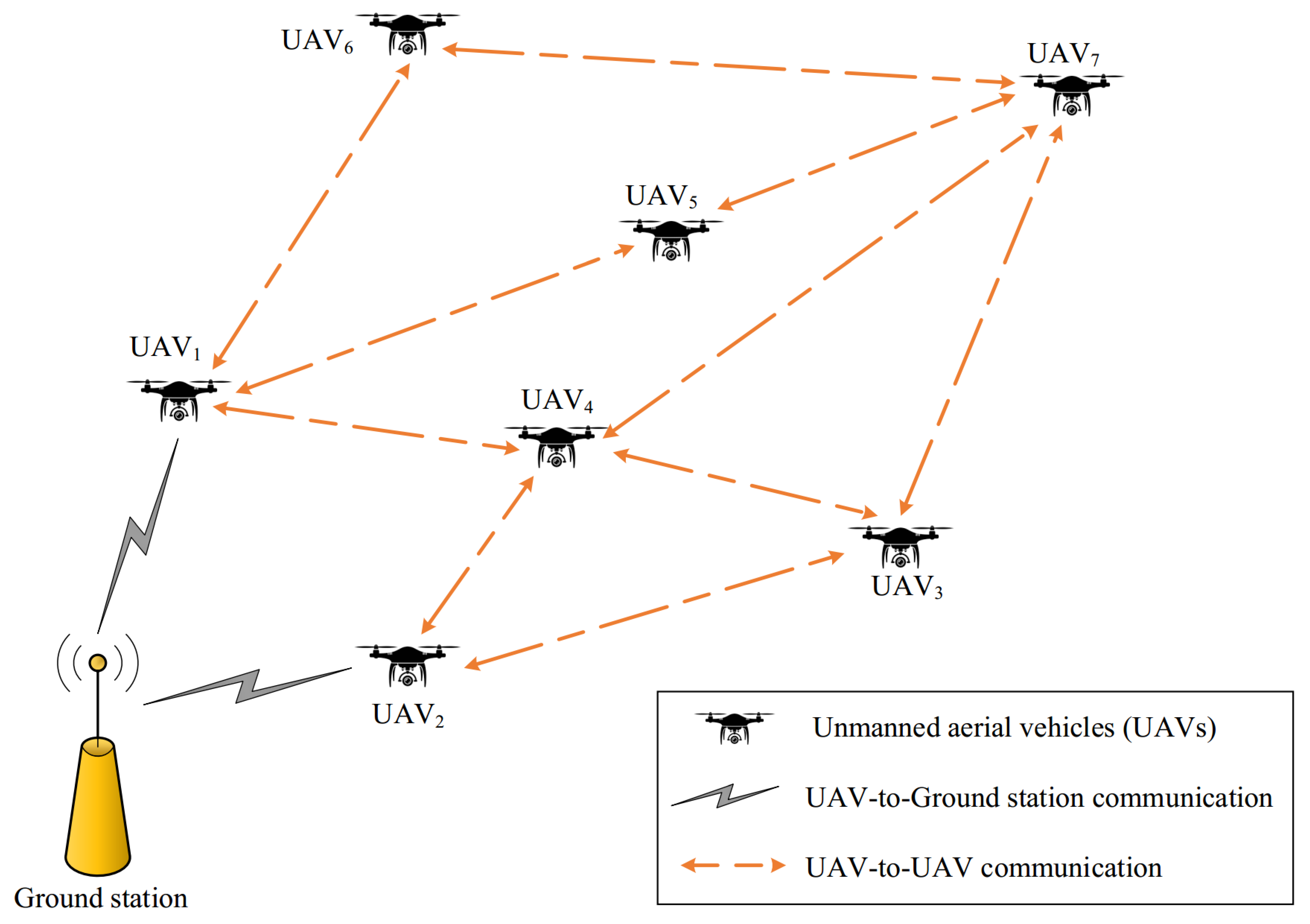
Figure 1. Network model in OLSR+GPSR.
Mathematics 12 01016 g001
Figure 2. Broadcasting hello messages in FANET.
Mathematics 12 01016 g002
Figure 3. Hello message format in OLSR+GPSR.
Mathematics 12 01016 g003
Figure 4. Fuzzy membership diagram of V i n o r m .
Mathematics 12 01016 g004
Figure 5. Fuzzy membership diagram of e i n o r m .
Mathematics 12 01016 g005
Figure 6. Fuzzy membership diagram of Δ t i .
Mathematics 12 01016 g006
Figure 7. Effective distance between U A V i and n p , i 1 h o p .
Mathematics 12 01016 g007
Figure 8. Evaluation of delay based on the number of UAVs.
Mathematics 12 01016 g008
Figure 9. Evaluation of delay based on the speed of UAVs.
Mathematics 12 01016 g009
Figure 10. Evaluation of PDR based on the number of UAVs.
Mathematics 12 01016 g010
Figure 11. Evaluation of PDR based on the speed of UAVs.
Mathematics 12 01016 g011
Figure 12. Evaluation of routing overhead based on the number of UAVs.
Mathematics 12 01016 g012
Figure 13. Evaluation of routing overhead based on the speed of UAVs.
Mathematics 12 01016 g013
Figure 14. Efficiency evaluation based on the number of nodes.
Mathematics 12 01016 g014
Figure 15. Evaluation of efficiency based on the speed of nodes.
Mathematics 12 01016 g015
Table 1. Benefits and drawbacks of various methods.
TechniqueStrengthsWeaknesses
[16]Improving various quality of services (QoS) requirements such as PDR, delay, throughput and energy consumption, suitable for the FANET environment, high link stability, managing routing overhead, high reliabilityLow scalability
P-OLSR [17]Improving various QoS requirements such as PLR, throughput, and delay, increasing link stabilityLow scalability, low adaptability to FANET because of not calculating an adaptive hello period
OLSR-ETX [18]Improving various QoS requirements such as PLR, throughput, delay, and energy consumptionLow scalability, lack of adaptability to the FANET environment, low reliability, low link stability
MWCRSF [19]Improving various QoS requirements such as throughput, delay, energy consumption, and PDR, increasing network scalability, rapid cluster construction, high cluster stabilityHigh time complexity, not calculating an adaptive hello period
AGGR [20]Improving various QoS requirements such as PDR, throughput, delay, and energy consumption, decreasing routing overhead, high adaptability to FANETLow scalability, not solving local optimization issue, dealing with routing loops
OLSR+ [21]Improving various QoS requirements such as PLR, throughput, and energy consumption, high adaptability to FANET, increasing reliabilityHigh routing overhead, low scalability
[22]Improving various QoS requirements such as PDR, throughput, delay, and energy consumption, increasing reliabilityHigh routing overhead, low scalability, low adaptability to FANET
[23]Improving various QoS requirements such as PDR, throughput, energy consumption, and delay, enhancing reliabilityHigh routing overhead, low scalability, not calculating an adaptive hello period
Table 2. Rule base.
Table 2. Rule base.
NumberFuzzy InputsFuzzy Output
V i norm e i norm Δ t i
1SlowLowIncrement
2SlowMediumChangeless
3SlowHighLow decrement
4MediumLowChangeless
5MediumMediumLow decrement
6MediumHighDecrement
7FastLowLow decrement
8FastMediumDecrement
9FastHighHigh decrement
Table 3. Simulation parameters.
ParameterValue
Simulation toolNS3
Network environment 3000 × 3000 × 3000 m3
Number of UAVs10–50
Velocity of UAVs10–50 m/s
Communication range of UAVs500 m
Initial energy of UAVs100 J
Execution time500 s
Packet size512 bytes
Traffic typeCBR
Mobility model3D GM
Mac protocolIEEE 802. 11b
Disclaimer/Publisher’s Note: The statements, opinions and data contained in all publications are solely those of the individual author(s) and contributor(s) and not of MDPI and/or the editor(s). MDPI and/or the editor(s) disclaim responsibility for any injury to people or property resulting from any ideas, methods, instructions or products referred to in the content.